INFORMATION SHEET LOW - Low Volume Vehicle · PDF fileLVVTA Information Sheet # 05‐2010 Page...
20
PO Box 13495, Johnsonville, Wellington 6440 Phone (04) 477 4372 Fax (04) 477 4374 E-mail [email protected] INFORMATION SHEET #05 ‐ 2010 December 2010 Page 1 of 20 LOW VOLUME VEHICLE TECHNICAL ASSOCIATION Inc Bump‐steer Swing‐check Procedure Introduction Bump‐steer, or ‘toe‐change on bump’, is the result of a steering geometry change which occurs when a vehicle’s suspension moves through its normal travel range. If left unchecked following geometry‐ altering modifications, this condition can lead to unpredictable and potentially dangerous steering and handling characteristics, which may or may not become evident under normal road‐test conditions. Due to bump‐steer being perceived by many as a ‘black science’, bump‐steer is often inadvertently engineered into a vehicle, due to the builder not having the level of understanding required to ensure that bump‐steer is minimised. This infosheet was developed to assist LVV Certifiers in performing a bump‐steer swing‐check on independent front or rear suspension systems. It also outlines the LVVTA solution and the procedures involved in completing a full bump‐steer swing‐check using the LVVTA developed bump‐steer swing‐ check bars. Background, and other related documents During the development of the bump‐steer swing‐check bars, LVVTA completed many bump‐steer swing‐ checks on a range of different vehicle types using differing methods, to ascertain whether the results provided by the LVVTA bump‐steer swing‐check bars were comparable with other ‘real world’ methods of measurement, such as wheel alignment machines, or a ‘pull‐down’ test where springs are not required to be removed. The results of this research can be found in a separate info‐sheet; ‘LVVTA Information Sheet # 04‐2010 ‐ Bump‐steer Background Information’. It is recommended that you study both documents to gain a more complete insight into this complex subject. Further information on this topic can also be found in a number of other publications. Additionally, there is an LVVTA form‐set (FS039) to assist in completing the measurement process – this form‐set should be completed and sent to LVVTA when requesting an LVV certification plate any time a bump‐steer swing‐check is completed. Over time, LVVTA will build a database recording these results, which will eventually allow us to ‘draw a line in the sand’ giving a range of acceptable limits. The LVVTA procedure LVVTA has, with input from expert low volume vehicle builders and LVV Certifiers, developed a procedure by which to perform a bump‐steer swing‐check that can be completed easily on most vehicles, including those that have front large spoilers, bumpers, or fender clearance issues. The bump‐steer swing‐check measuring bars have been designed to fit onto the majority of front hubs, and to make the measuring process repeatable, quick and accurate. Whilst there are other methods of checking for bump‐steer, LVVTA recommends the following method to provide consistent results between all LVV Certifiers. If an LVV Certifier has a different or alternative method, please ensure LVVTA is satisfied with the method to ensure that data from all LVV Certifiers remains consistent.
Transcript of INFORMATION SHEET LOW - Low Volume Vehicle · PDF fileLVVTA Information Sheet # 05‐2010 Page...

PO Box 13495, Johnsonville, Wellington 6440
Phone (04) 477 4372 Fax (04) 477 4374 E-mail [email protected]
I N F O R M A T I O N S H E E T #0 5 ‐ 2 0 1 0 December 2010 Page 1 of 20
LOW V O L U M E
V E H I C L E T E C H N I C A L
A S S O C I A T I O N I n c
Bump‐steer Swing‐check Procedure Introduction Bump‐steer, or ‘toe‐change on bump’, is the result of a steering geometry change which occurs when a vehicle’s suspension moves through its normal travel range. If left unchecked following geometry‐altering modifications, this condition can lead to unpredictable and potentially dangerous steering and handling characteristics, which may or may not become evident under normal road‐test conditions. Due to bump‐steer being perceived by many as a ‘black science’, bump‐steer is often inadvertently engineered into a vehicle, due to the builder not having the level of understanding required to ensure that bump‐steer is minimised. This infosheet was developed to assist LVV Certifiers in performing a bump‐steer swing‐check on independent front or rear suspension systems. It also outlines the LVVTA solution and the procedures involved in completing a full bump‐steer swing‐check using the LVVTA developed bump‐steer swing‐check bars. Background, and other related documents During the development of the bump‐steer swing‐check bars, LVVTA completed many bump‐steer swing‐checks on a range of different vehicle types using differing methods, to ascertain whether the results provided by the LVVTA bump‐steer swing‐check bars were comparable with other ‘real world’ methods of measurement, such as wheel alignment machines, or a ‘pull‐down’ test where springs are not required to be removed. The results of this research can be found in a separate info‐sheet; ‘LVVTA Information Sheet # 04‐2010 ‐ Bump‐steer Background Information’. It is recommended that you study both documents to gain a more complete insight into this complex subject. Further information on this topic can also be found in a number of other publications. Additionally, there is an LVVTA form‐set (FS039) to assist in completing the measurement process – this form‐set should be completed and sent to LVVTA when requesting an LVV certification plate any time a bump‐steer swing‐check is completed. Over time, LVVTA will build a database recording these results, which will eventually allow us to ‘draw a line in the sand’ giving a range of acceptable limits. The LVVTA procedure LVVTA has, with input from expert low volume vehicle builders and LVV Certifiers, developed a procedure by which to perform a bump‐steer swing‐check that can be completed easily on most vehicles, including those that have front large spoilers, bumpers, or fender clearance issues. The bump‐steer swing‐check measuring bars have been designed to fit onto the majority of front hubs, and to make the measuring process repeatable, quick and accurate. Whilst there are other methods of checking for bump‐steer, LVVTA recommends the following method to provide consistent results between all LVV Certifiers. If an LVV Certifier has a different or alternative method, please ensure LVVTA is satisfied with the method to ensure that data from all LVV Certifiers remains consistent.

LVVTA Information Sheet # 05‐2010 Page 2 of 20
LVVTA Bump‐steer swing‐check bars
• Image 1 – Bump‐steer swing‐check bars are shown attached to the backing board. Four metal spacers and
wing‐nuts secure the bars to the board. The LVVTA supplied bump‐steer bars have a black powder‐coat finish.
Image 2 – This shows an expanded view of the bump‐steer swing‐check bars showing the levelling legs and spacers.
Notes:
• For information relevant to checking a vehicle with mudguards and strut type suspension, see photos 38 to 43.
• The LVVTA Bump‐steer swing‐check bars are not designed for wheel alignment set‐up purposes.
• The vehicle’s static ride height is the vehicle’s normal ride height with no passengers.
• The increments provided for raising and lowering the suspension are a guide only. Utilise a selection of timber off‐cuts in varying sizes from your local timber yard.
• The red marks on the bump steer bars are set at 575 mm apart, and are a guide to locate the tape measure when reading toe. The distance between the two marks is 575 mm, and represents an average tyre diameter. This also makes it simple to convert between degrees and mm – 575 mm distance always gives a 10:1 ratio of mm to degrees, so when the toe on the bars measure 10 mm, this equals 1 degree of toe. Note that the location of the red marks depicted in this Infosheet differs from the location on the LVVTA bump‐steer swing‐check bars.
• Once the bars have been levelled, the brakes can be applied and locked to keep bars parallel.
• A small spirit level can also be used to ensure bars are level throughout the measuring process.
• To advise on the best way to fix bump‐steer, see LVVTA Bump‐steer Background Infosheet #05‐2010.
• If problems are identified with steering arms or joints contacting suspension arms (Image 37), some options to remedy the situation are;
o reposition rack; or
o alter length of the steering rack; or
o change the steering arms.

LVVTA Information Sheet # 05‐2010 Page 3 of 20
The LVVTA Procedure:
1. Place vehicle at nominal ride height on a flat and even surface. (Image 3)
Image 3 ‐ vehicle at nominal ride height.
2. Measure and record the vehicles nominal ride height off the suspension beam. (Image 4)
Image 4 ‐ measuring nominal ride height off suspension beam.
3. Measure and record the length of the installed coil‐over shocks at nominal ride height from top to bottom anchorage points. (Image 5 and 6)
Image 5 ‐ measuring length of coil‐over shocks from top and bottom mounting points at nominal ride height.

LVVTA Information Sheet # 05‐2010 Page 4 of 20
Image 6 ‐ Close up of measuring coil‐over shocks installed length.
4. Check the cross‐member to chassis fitment, ensuring all welding or bolting meets the requirements specified in 18.7 and 18.8 (for welding), and 18.2 to 18.6 (for bolting) of the NZ Hobby Car Technical Manual.
5. Check to ensure that there is adequate caster built into the suspension. (Image 7)
Image 7 ‐ visual check of caster viewed from the side of the car, the top ball‐joint should be positioned behind the bottom one for positive caster.

LVVTA Information Sheet # 05‐2010 Page 5 of 20
6. Remove the coil springs and shocks from the vehicle. (Image 8)
Image 8 ‐ remove coil‐over shocks.
7. If fitted, disconnect the sway bar links at the suspension arms. Set the vehicle onto blocks at the suspension beam nominal ride height. Remove jack. (Image 9)
Image 9 – vehicle cross‐member supported by blocks, checking that it is still at nominal ride height.
8. Remove road wheels. (Image 10)
Image 10 ‐ remove road wheels.
LVVTA Information Sheet # 05‐2010 Page 6 of 20
9. Check the suspension arm maximum droop travel is greater than the maximum shock
absorber length. (Image 11)
Image 11 ‐ shock fitted at top mount showing suspension with further travel than the shock length, which is needed to prevent ball joint binding.
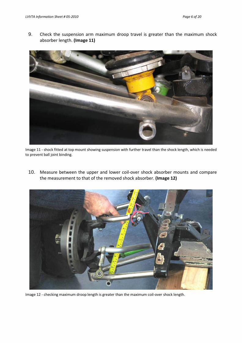
10. Measure between the upper and lower coil‐over shock absorber mounts and compare the measurement to that of the removed shock absorber. (Image 12)
Image 12 ‐ checking maximum droop length is greater than the maximum coil‐over shock length.
LVVTA Information Sheet # 05‐2010 Page 7 of 20
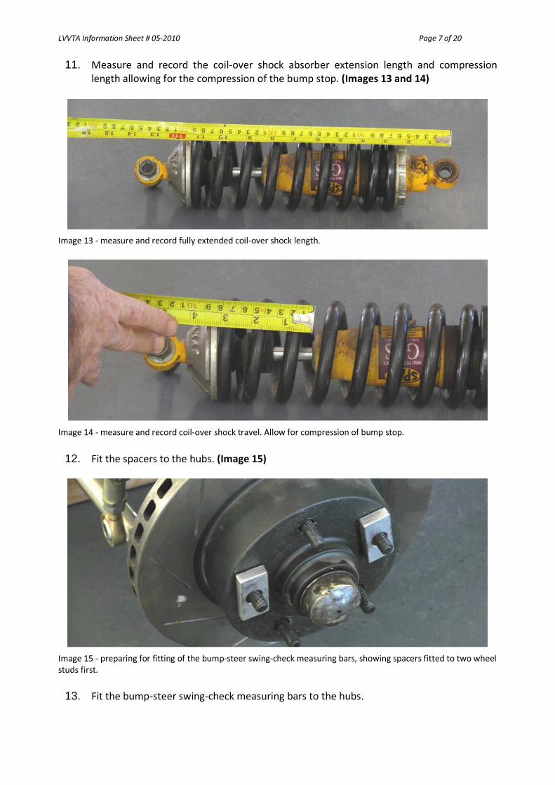
11. Measure and record the coil‐over shock absorber extension length and compression length allowing for the compression of the bump stop. (Images 13 and 14)
Image 13 ‐ measure and record fully extended coil‐over shock length.
Image 14 ‐ measure and record coil‐over shock travel. Allow for compression of bump stop.
12. Fit the spacers to the hubs. (Image 15)
Image 15 ‐ preparing for fitting of the bump‐steer swing‐check measuring bars, showing spacers fitted to two wheel studs first.
13. Fit the bump‐steer swing‐check measuring bars to the hubs.

LVVTA Information Sheet # 05‐2010 Page 8 of 20
14. The bump‐steer swing‐check measuring bars can be fitted on to the studs with any of the three holes in each bar to allow for clearance. Ensure the bars are located and positioned the same on both sides. (Image 16)
Image 16 ‐ Installation of the bars. The bars can be fitted on to the studs with any of the three holes in each bar.
15. Make sure that at full droop, the bars are clear of the ground at the hub area, and the bars are adjusted to level at the forward end with the droop bracket. (Image 17)
Image 17 ‐ check that the bars are clear of the floor at full suspension droop.
16. Place blocks under the discs until the suspension is sitting at nominal ride height. Check this by measuring between the coil‐over shock absorber anchorage points. This is the distance recorded in Step 3. (Image 18 and 19)
Image 18 ‐ fit blocks under disks to set suspension arms at nominal ride height.

LVVTA Information Sheet # 05‐2010 Page 9 of 20
Image 19 ‐ checking the nominal ride height by measuring between the coil‐over shock absorber mounts and comparing to the measurements recorded in step 3 (see photos 5 and 6).
17. Check to ensure that the steering rack or steering box is centred, and adjust if necessary. Adjust the steering tie‐rods until wheels are situated in the straight‐ahead position, ensuring tie rods are of equal length side to side. (Image 20)
Image 20 ‐ Ensure the tie rods are equal length each side during the adjustment process.
18. To prevent the steering from moving during the measurement process, it is recommended that the steering is locked. This can be achieved by using a steering wheel‐lock (commonly used in wheel alignment) (Image 21) or can be mechanically locked by clamping the steering shaft or column in the straight ahead position.

LVVTA Information Sheet # 05‐2010 Page 10 of 20
Image 21 – locking the steering. A tool such as this is available from automotive equipment suppliers.
19. Ensure the bump‐steer swing‐check measuring bars are level to the floor and maintain the position using the droop bracket. (Image 22)
Image 22 ‐ Make sure the measuring bars are centralised, level and clear of the ground. (Passengers side)

LVVTA Information Sheet # 05‐2010 Page 11 of 20
20. Measure and record the distances A to A, and then B to B. (Image 23 and 24)
Image 23 ‐ Measure and record the distance A to A.
Image 24 ‐ Measure and record the distance B to B.
21. Set the toe to parallel at the nominal ride height by measuring A to A and B to B until both measurements are identical. (Image 25 and 26)
Image 25 ‐ Adjust the tie rods to give a nominal toe of zero.
LVVTA Information Sheet # 05‐2010 Page 12 of 20
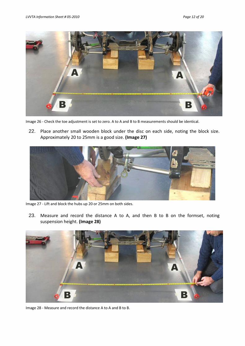
Image 26 ‐ Check the toe adjustment is set to zero. A to A and B to B measurements should be identical.
22. Place another small wooden block under the disc on each side, noting the block size. Approximately 20 to 25mm is a good size. (Image 27)
Image 27 ‐ Lift and block the hubs up 20 or 25mm on both sides.
23. Measure and record the distance A to A, and then B to B on the formset, noting suspension height. (Image 28)
Image 28 ‐ Measure and record the distance A to A and B to B.

LVVTA Information Sheet # 05‐2010 Page 13 of 20
24. Repeat steps 22 and 23, (Image 27 and 28), until the measurement between the upper and lower coil‐over shock absorber anchorages are the same as the coil‐over shock absorber measurements at full compression.
25. Once this point is reached lift the suspension to make sure there is some travel left in the
suspension before the suspension joints bind. (Image 29)
Image 29 ‐ Lift the suspension to ensure the suspension arms will travel further than the minimum coil‐over shock length. This is to ensure there is more travel available before the suspension joints bind. Complete this check on both sides.
26. Remove all blocks to allow the suspension arms to go to full droop (to when the
suspension joints bind). (Image 30)
Image 30 – Blocks removed from driver’s side showing suspension at full droop.

LVVTA Information Sheet # 05‐2010 Page 14 of 20
27. Check measurements between coil‐over shock absorber upper and lower mounts to see that full droop is more travel than is available in the coil‐over shock absorbers. (Image 31)
Image 31 ‐ Suspension arms down at full droop.
28. Measure and record the distance A to A and B to B. (Image 32)
Image 32 ‐ Measure and record the measurements A to A and B to B.
29. Place blocks under the discs until the suspension arms are sitting at their nominal ride height. This is the distance recorded in Step 3. (Image 5 and 6)

LVVTA Information Sheet # 05‐2010 Page 15 of 20
Image 33 ‐ Place blocks under the discs until the suspension arms are sitting at the nominal ride height.
30. Check that the vehicle has Ackerman. Unlock the steering, and turn hubs to full lock left. (Image 34)
Image 34 ‐ Image shows steering arms turned to show zero to positive Ackerman angle (bars should be parallel or taper outwards).
31. Measure and record the distance A to A and B to B. 32. To show that the suspension has positive Ackerman, there should be toe‐out (A to A is
less than B to B).
33. Turn hubs to full lock right.
34. Repeat step 31.
35. Return steering to straight ahead position, and lock.
36. Continue to lower down in 20 to 25 mm increments and measure and record distances A to A and B to B at each height increment until full coil‐over shock length is reached. (Image 35)

LVVTA Information Sheet # 05‐2010 Page 16 of 20
Image 35 ‐ Continue to lower down in 20 to 25mm increments and measure and record distances A to A and B to B at each height until full coil‐over shock length is reached.
37. Remove all blocks to allow the suspension arms to go to full droop (to when the suspension joints bind), and remove the bump‐steer swing‐check measuring bars.
38. Check the suspension at full lock throughout the available suspension travel to ensure
the steering does not bind or whether any steering, suspension or brake components touch. (Image 36). This is an important check to perform at both locks while lifting the hubs throughout the available suspension travel as it will ensure there is no suspension bind.
Image 36 – This Image shows the steering tie rod adjusted to demonstrate the possibility of tie rod interference with the suspension arms.

LVVTA Information Sheet # 05‐2010 Page 17 of 20
39. Check the steering does not go over centre. (Image 37)
Image 37 ‐ On this vehicle, the very straight angle between steering arm and tie rod will cause the inside wheel to over‐centre.
40. Refit coil‐over shocks and road wheels, and set vehicle back onto the ground. Photos 38 to 43. The following photographs show the bump‐steer swing‐check measuring bars being used on a vehicle with McPherson struts, and mudguards. In most cases the method of performing the check is similar, however the coil springs must be removed from the McPherson struts, and the struts refitted into the vehicle. In order to save time, a pair of trolley jacks can be located underneath the front disc rotors, removing the need for multiple wooden blocks. LVVTA has used this method successfully. Measurements can be taken from the wheel or hub centres, to the centre of the wheel arch on the mudguards.
Image 38 ‐ Example of a vehicle with mudguards jacked up to nominal ride height and blocked.

LVVTA Information Sheet # 05‐2010 Page 18 of 20
Image 39 ‐ Spacers fitted to hubs.
Image 40 ‐ Bump‐steer swing‐check measuring bars fitted.
Image 41 ‐ Showing gap below bars and floor.

LVVTA Information Sheet # 05‐2010 Page 19 of 20
Image 42 ‐ To check this type of strut suspension the coil springs will need to be removed first, and the struts re‐installed.
Image 43 ‐ Measure across and under the bumper, spoiler or fenders A to A, and then B to B. Photos 43 to 45. The bump‐steer swing‐check measuring bars being shown through the full height range with the droop bracket being used to level the bars.
Image 44 ‐ Measuring bars with the droop bracket at the front end which allows for height levelling before measuring. (At full droop)

LVVTA Information Sheet # 05‐2010 Page 20 of 20
Image 45 ‐ Measuring bars with the droop bracket at the front end which allows for height levelling before measuring. (At nominal ride height)
Image 46 ‐ Measuring bars with the droop bracket at the front end which allows for height levelling before measuring. (At full compression) With the information recorded onto the LVVTA bump‐steer swing‐check form‐set, you can now graph the information to show the total amount of toe change throughout the suspension travel. If you have any queries or require any further clarification relating to this Information Sheet, please feel free to contact one of the Technical Team at the LVVTA office. Justin Hansen Technical Officer Low Volume Vehicle Technical Association Inc