Information fusion concepts for airborne maritime ...
114
Information fusion concepts for airborne maritime surveillance and C 2 operations P. Valin É. Bossé A. Jouan DRDC Valcartier Defence R&D Canada – Valcartier Technical Memorandum DRDC Valcartier TM 2004-281 May 2006
Transcript of Information fusion concepts for airborne maritime ...

Information fusion concepts for airborne
maritime surveillance and C2 operations
P. ValinÉ. BosséA. JouanDRDC Valcartier
Defence R&D Canada – ValcartierTechnical Memorandum
DRDC Valcartier TM 2004-281May 2006


Information fusion concepts for airbornemaritime surveillance and C2 operations
P. ValinÉ. BosséA. JouanDRDC Valcartier
Defence R&D Canada - ValcartierTechnical MemorandumDRDC Valcartier TM 2004-281
May 2006

Author
Pierre Valin
Approved by
Éloi BosséSection Head, Decision Support Systems
Approved for release by
Gilles Bérubé
Chief Scientist
This report is the first in a series of 3 reports summarizing the results of PWGSC Contract No.W7701-6-4081 on Real-Time Issues and Demonstrations of Data Fusion Concepts forAirborne Surveillance (Dr. Pierre Valin, Principal Investigator), and PWGSC Contract No.W2207-8-EC01, on Demonstrations of Image Analysis and Object Recognition DecisionAids for Airborne Surveillance (Dr. Alexandre Jouan, Principal Investigator), under theScientific Authority of Dr. Éloi Bossé. The other 2 reports are entitled Airborne Applicationof Information Fusion Algorithms to Classification (DRDC-V TR-2004-282) andDemonstration of Data/Information Fusion Concepts for Airborne Maritime Surveillance
Operations (DRDC-V TR-2004-283).
© Her Majesty the Queen as represented by the Minister of National Defence, 2006
© Sa majesté la Reine, représentée par le ministre de la Défense nationale, 2006

DRDC Valcartier TM 2004-281 i
Abstract
The objective of the report is to address the problem of Multi-Source Data Fusion on boardthe airborne maritime surveillance CP-140 (Aurora) aircraft. To that end, a survey of theconcepts that are needed for data/information fusion is made, with the aim of improvingCommand and Control (C2) operations. All of the current and planned sensors are describedand their suitability for fusion is discussed. Relevant missions for the aircraft are listed, andthe focus is placed on a few important ones that make full use of the Aurora s sensor suite.The track update process with the fusion function involves both positional and identificationcomponents. For the latter, a comprehensive set of a priori databases contains all theinformation/knowledge about the platforms likely to be encountered on missions. The mostimportant of these is the Platform DataBase (PDB), which lists all the attributes that can bemeasured by the sensors (with accompanying numerical or fuzzy values), and these can be ofthree types: kinematical, geometrical or directly in terms of the identity of the target platformitself. The PDB used is given in an appendix.
Résumé
Ce rapport aborde la problématique de la fusion multicapteur à bord de la plate-formeaéroportée CP-140 (Aurora) lors de ses missions de surveillance maritime. À cette fin, on faitun survol des concepts requis pour la fusion des données et de l information, dans le but
améliorer les opérations de commande et de contrôle. Tous les capteurs actuels et prévussont énumérés et leur utilisation dans le processus de fusion est discutée. On présente lesmissions possibles de l Aurora et on choisit quelques-unes qui utilisent la suite complète descapteurs. La mise à jour de l information contenue dans une piste comprend une composantepositionnelle et une autre reliée à l identité. Pour cette dernière tâche, un ensemble completde bases de données a priori doit contenir toute l information et la connaissance de toutes lesplates-formes qui pourraient être rencontrées lors de missions. La plus importante de cesbases de données a priori est la base de données sur les plates-formes elles-mêmes, quiénumère tous les attributs pouvant être mesurés par les capteurs (avec une valeur numériqueou floue), lesquels peuvent être de 3 types: cinématique, géométrique ou relié directement à
identité de la plate-forme ciblée. La base de données utilisée est donnée en appendice.

ii DRDC Valcartier TM 2004-281
This page intentionally left blank.

DRDC Valcartier TM 2004-281 iii
Executive summary
The mission requirements against which the majority of currently operational defenceplatforms have been designed, have been impacted by a significant evolution of the sensorsprobing its environment. In particular, operating in a more cluttered electromagnetic as wellas physically constrained and busy environment imposes the following requirements: higherdegree of situation awareness, computer-aided platform identification, and faster reactiontimes. Such convictions motivated Canada s Department of National Defence to perform andcontract R&D work in various decision aid technologies such as Data Fusion and Imaging.Lockheed Martin (LM) Canada has also applied significant effort researching thesetechnologies since 1990 as independent R&D as well as in collaboration with Defence R&DCanada establishments in Valcartier (DRDC Valcartier) and in Ottawa (DRDC Ottawa).Since 1988, DRDC Valcartier has been playing a major role in the development of decisionsupport technologies such as Data Fusion and Knowledge-Based Systems for applications inCommand, Control, Communications, Computer and Intelligence (C4I) systems.
This memorandum will provide a description of the DRDC-V program, which creates ademonstration system for an Airborne Mission Management System in a collaborative effortwith LM Canada, DRDC Ottawa and Canadian universities.
This document is a review of the information fusion concepts needed for Multi-Sensor DataFusion (MSDF) for airborne maritime surveillance sensors, such as those on board the CP-140aircraft (current and planned future upgrades), with the final goal of achieving betterCommand and Control (C2) operations for relevant mission scenarios. More precisely, thisdocument provides the necessary background for the next two reports.
In particular, this document lists:
a. The characteristics of all the current and foreseen sensors for the CP-140;
b. What scenarios and missions need to be addressed and at which level ofreality;
c. The available data fusion and data/information fusion architectures, processesand algorithms; and
d. The set of a priori databases needed for identity estimation using theattributes measured by the sensors.
The technical objectives of this series of three reports are incremental demonstrations of datafusion for surveillance aircraft, incorporating state-of-the-art tracking and evidential reasoningfor target identification (ID). This Data Fusion Demonstration Model (DFDM) for airbornesurveillance intentionally ignores all sensors pertaining to Underwater Surveillance andControl (USC).
Valin, P., Bossé, É., Jouan, A. (2006). Information fusion concepts for airborne maritimesurveillance and C2 operations, DRDC Valcartier TM 2004-281.

iv DRDC Valcartier TM 2004-281
Sommaire
Les conditions de mission qui ont motivé la conception de la majorité des plates-formesmilitaires présentement en opération, ont été modifiées par l évolution significative descapteurs qui scrutent l environnement. En particulier, les opérations dans un environnementélectromagnétique complexe, de même que dans une situation physique contraignante etcompliquée imposent de nouvelles conditions : un degré élevé de conscience de la situation,
identification aidée par ordinateur de plates-formes, et de meilleurs temps de réaction. Detelles convictions ont motivé le Ministère de la Défense nationale du Canada de mener et desous-traiter de la recherche et développement (R&D) dans les technologies des aides à ladécision telles que la fusion des données et l imagerie. Lockheed Martin (LM) Canada a aussiinvesti un effort important dans des recherches de ce genre depuis 1990, à titre de rechercheinterne indépendante ou en collaboration avec les groupes de R&D de la défense du Canada àValcartier (RDDC Valcartier) et à Ottawa (RDDC Ottawa). Depuis 1988, RDDC Valcartier ajoué un rôle majeur dans le développement de technologies appropriées aux aides à ladécision telles que la fusion de données et les systèmes de connaissance à base de donnéespour des applications aux systèmes C4I.
Ce mémorandum décrira le programme de RDDC Valcartier, qui élabore un système pour ladémonstration d un « Airborne Mission Management System » développé de concert avecLM Canada, RDDC Ottawa et des universités canadiennes.
Ce document passe en revue les concepts nécessaires pour la fusion de données multicapteurpour les capteurs appropriés aux missions aéroportées de surveillance maritime, tels que ceuxà bord de l aéronef CP-140 (avec les capteurs présentement en action et leurs améliorationsfutures), dans le but final d opérations C2 plus performantes pour les scénarios de missionappropriés. Plus précisément, ce document se veut la toile de fond qui servira aux deuxprochains rapports.
En particulier, ce document décrit :1. les caractéristiques des capteurs existants et envisagés pour le CP-1402. les scénarios et missions qui doivent être abordés et leur niveau de réalisme dans les
simulations3. les architectures, processus et algorithmes existants pour la fusion de données et de
information4. les bases de données a priori qui sont nécessaires pour l estimation de l identité à
partir des mesures faites par les capteurs des attributs de la cible
Les objectifs techniques de ce tryptique consistent en des démonstrations évolutives de lafusion de données pour un aéronef de surveillance contenant un pistage ultramoderne et lemeilleur raisonnement évidentiel pour obtenir l identité (ID) de toute cible. Ce modèle dedémonstration de la fusion de données pour la surveillance aéroportée écarteintentionnellement les capteurs reliés à la surveillance sous-marine.
Valin, P., Bossé, E, Jouan, A. (2006). Information fusion concepts for airborne maritimesurveillance and C2 operations, DRDC Valcartier TM 2004-281.

DRDC Valcartier TM 2004-281 v
Table of contents
Abstract ... i
Résumé ... i
Executive Summary ..iii
Sommaire ..iv
Table of contents v
List of figures ix
List of tables ...x
1. Introduction ...............................................................................................................1
2. Maritime operations context.......................................................................................3
2.1 CP-140 (Aurora) roles ...................................................................................3
2.1.1 Tactical environment ........................................................................9
2.1.2 Environmental conditions .................................................................9
2.1.3 Why does one need data fusion?......................................................11
2.1.4 Expected pay-offs ...........................................................................11
2.2 CP-140 information sources ........................................................................12
2.2.1 AN/APS-506 search radar ...............................................................12
2.2.2 AN/APX-502 IFF ...........................................................................15
2.2.3 AN/ALR-502 ESM.........................................................................16
2.2.4 OR-5008/AA Forward Looking Infra-Red (FLIR)...........................18
2.2.5 Data link (Link-11) .........................................................................20
2.2.6 Synthetic Aperture Radar (SAR) .....................................................22
StripMap 24
Range Doppler Profiler (RDP) ........................................................25
Spotlight 25
2.2.7 Characterization of CP-140 information sources..............................27
2.2.8 Operational environment of CP-140 sensors....................................28
2.3 Definition of data/information fusion scenarios............................................29
2.3.1 SCENARIO 1: Maritime air area operations....................................30

vi DRDC Valcartier TM 2004-281
2.3.2 SCENARIO 2: Direct fleet support .................................................34
2.3.3 SCENARIO 3: Counter-drug operations.........................................37
2.3.4 SCENARIO 4: Maritime sovereignty patrols...................................40
3. Data/Information fusion process and architecture .....................................................43
3.1 Multi-source data fusion architecture ...........................................................43
3.1.1 Contact/Attribute level fusion .........................................................43
3.1.2 Track/Declaration level fusion ........................................................44
3.1.3 Hybrid approach .............................................................................44
3.2 Multi-source data fusion process..................................................................45
3.2.1 Single platform positional fusion.....................................................45
Data registration .............................................................................46
Data association..............................................................................47
Positional update.............................................................................49
Track management process .............................................................50
3.2.2 Single platform identity information fusion .....................................50
3.2.3 Multi-platform positional/identity fusion.........................................51
4. A priori Information.................................................................................................52
4.1 Databases ....................................................................................................52
4.1.1 Baseline platform database..............................................................52
4.1.2 Extended platform database ............................................................59
4.1.3 Higher level STA/RM databases .....................................................61
4.2 STANAG 4420 and MIL-STD 2525............................................................62
4.2.1 Sea surface domain .........................................................................63
4.2.2 Subsurface domain..........................................................................66
4.2.3 Air domain......................................................................................67
4.2.4 Ground or land domain ...................................................................69
5. Conclusion...............................................................................................................70
6. References ...............................................................................................................71
7. Acronyms ................................................................................................................74
8. Annexes...................................................................................................................78

DRDC Valcartier TM 2004-281 vii
8.1 Main sources of documentation ...................................................................78
8.1.1 General data/information fusion sources..........................................78
8.1.2 Specific related data/information fusion sources ..............................79
8.2 Platform DataBase (PDB)............................................................................81
8.3 Emitter Name List (ENL) ............................................................................88
9. Distribution list ........................................................................................................93

viii DRDC Valcartier TM 2004-281
This page intentionally left blank.

DRDC Valcartier TM 2004-281 ix
List of figures
Figure 1. Air targets and rough locations of surface targets for maritime air area operationsscenario.........................................................................................................................31
Figure 2. Detailed locations and directions of surface targets for maritime air area operationsscenario.........................................................................................................................33
Figure 3. Ships and aircraft in direct fleet support operations ................................................35
Figure 4. Canadian and American ship formations for direct fleet support operations ...........37
Figure 5. Close-up of drug smuggling ships off St. John s....................................................39
Figure 6. flight profile and ships involved in the counter-drug operations mission.................40
Figure 7. Fishing banks and management zones of the eastern seashore ................................41
Figure 8. Aurora flight profile for maritime sovereignty patrol mission .................................42
Figure 9 STANAG 4420 classification.................................................................................65
x DRDC Valcartier TM 2004-281
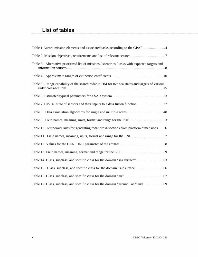
List of tables
Table 1 Aurora mission elements and associated tasks according to the GPAF........................4
Table 2 Mission objectives, requirements and list of relevant sensors.....................................7
Table 3 - Alternative prioritized list of missions / scenarios / tasks with expected targets andinformation sources .........................................................................................................8
Table 4 - Approximate ranges of extinction coefficients........................................................10
Table 5 - Range capability of the search radar in DM for two sea states and targets of variousradar cross-sections .......................................................................................................15
Table 6 Estimated typical parameters for a SAR system.......................................................23
Table 7 CP-140 suite of sensors and their inputs to a data fusion function ............................27
Table 8 Data association algorithms for single and multiple scans.......................................48
Table 9 Field names, meaning, units, format and range for the PDB....................................53
Table 10 Temporary rules for generating radar cross-sections from platform dimensions .....56
Table 11 Field names, meaning, units, format and range for the ENL..................................57
Table 12 Values for the GENFUNC parameter of the emitter ...............................................58
Table 13 Field names, meaning, format and range for the GPL ............................................59
Table 14 Class, subclass, and specific class for the domain sea surface .............................63
Table 15 Class, subclass, and specific class for the domain subsurface .............................66
Table 16 Class, subclass, and specific class for the domain air ..........................................67
Table 17 Class, subclass, and specific class for the domain ground or land ....................69

DRDC Valcartier TM 2004-281 1
1. Introduction
Modern military operations take place within an enormously complex environment toaccomplish missions across the spectrum of operations from humanitarian assistance to high-intensity combat. In the past several decades, the battlespace has expanded tremendously inthe face of increasingly powerful and accurate weapons capable of being launched atprogressively greater ranges from their targets. In response to these challenges, powerful newsensors have been deployed at sea, ashore and in space, while the capacity of communicationssystems has multiplied to make available huge volumes of data and information tocommanders and their staffs. In short, technological improvements in mobility, range,lethality and information acquisition continue to compress time and space, forcing higheroperating tempos and creating greater demands on command decision-making. Uncertaintyand time are thus the two factors that dominate the environment in which military decisionsare made.
The Decision Cycle is based on Col. John R. Boyd s OODA Loop (Observe, Orient,Decide, Act), and is the model adopted in this report for the information and decision-makingprocesses that lie at the heart of Command and Control (Boyd, 1986). If the blue forceperforms the OODA cycle faster than the red force, battlespace superiority is assured. TheOODA loop hinges on the fulfilment of two broad functions: first, that all commanders in aforce arrive at a shared and consistent understanding of the battlespace arising throughbattlespace awareness; and, second, that unity of effort is achieved throughout a joint andcombined force through commonly held intent. Within the R&D community, one often refersto situation awareness and decision-making.
In this report, the focus will be on situation awareness aspects through the data fusion process.Canada s airborne platforms, through the CP-140 Aurora Incremental Modernization Program(AIMP) and the Maritime Helicopter Program (MHP), require solutions for automatedMission Management Systems for the new millennium. The sensor suite for typical airbornemaritime surveillance includes a Synthetic Aperture Radar (SAR), a Forward Looking Infra-Red (FLIR) imaging sensor, as well as non-imaging sensors such as radar, InterrogationFriend or Foe (IFF), Electronic Support Measures (ESM), and datalink information. For navaltargets, the SAR mode usually employed is the Spotlight SAR (SSAR mode, which adjuststhe imaging radar within the centre of a spot . The varied data coming from such a broadrange of sensors require Multi-Sensor Data Fusion (MSDF) techniques to avoid operatoroverload and provide a global tactical picture with increased efficiency.
This report will therefore define
• What is the problem?
• Why does one need data fusion?
and also state the
• Assumptions, i.e., the current suite of sensors and the expected upgrades
2 DRDC Valcartier TM 2004-281
• Limitations of our study, i.e., no underwater applications, together with a selectedchoice of sensors to be fused.
A second report entitled Airborne Application of Information Fusion Algorithms toClassification will discuss the SAR and FLIR Image Support Modules (ISM) that have beendesigned and tested on simulated and real imagery for both imaging sensors. These ISMsconsist of multi-stage hierarchical intelligent classifiers that extract relevant imagery featuresand provide possible platform identification. This information is then fused with all thepreviously accumulated identity information for the correlated track, thus providing anautomated method for unique platform identification, which can be under operator control ifneeded.
A status of the development of these algorithms on an LM Canada/DRDC-V Black Board(BB)-based Knowledge-Based System (KBS) will be presented in a third report entitledDemonstration of Data/Information Fusion Concepts for Airborne Maritime Surveillance
Operations, as well as performance results on simulated data (both tracking and imagery)mainly for two relevant scenarios, namely Maritime Air Area Operations (MAAO) and DirectFleet Support (DFS).
The report is organized as follows.
• Section 2 describes the maritime operations context that will be studied, and links thedata fusion process with situation awareness.
• Section 3 presents the multi-source data fusion system with emphasis on the identity(ID) information fusion process.
• Section 4 contains all the a priori information that is needed to achieve a correct ID.
• Section 5 provides a summary and conclusions.

DRDC Valcartier TM 2004-281 3
2. Maritime operations context
A study funded by the Chief of Research and Development (CRAD) entitled Feasibilitystudy on sensor data fusion for the CP-140 aircraft (Bossé & Roy, 1996) analyzed thefollowing:
a. CP-140 operational environment as defined in terms of:
1) Mission requirements (e.g., USC, Surface Surveillance and Control(SSC), target tracking, goals, etc.)
2) Tactical environment (e.g., threat scenarios, enemy jamming, etc.)
3) Environmental conditions to determine their impact on sensorperformance (e.g., rain, fog, clutter, multi-path, etc.)
4) Typical scenarios in which the sensor information is being collected.
b. CP-140 information sources with particular emphasis on the informationthat should be fused, based upon an analysis of:
1) The sensor information from the current sensor suite versus theinformation from an advanced suite of the same types of sensors
2) The information available from additional sensors on board theaircraft
3) Information from other sources.
The operational environment must also be described as it pertains to the generation ofappropriate scenarios, the population of the different databases (platform, emitter, geo-political, etc.), and the random sensor errors that inevitably occur due to fluctuating weatherconditions affecting independently the Aurora as a platform and the performance of itssensors under possible adverse conditions. A quick review of both the sensors and theoperational environment will put the demands on the simulators and the scenario generator inthe proper perspective.
The information sources, which are the sensors in the context of this report, must be properlymodelled by the different simulators used, particularly with regards to the intrinsic accuracyachievable. The Communications Intercept Operator (CIO) is not modelled.
2.1 CP-140 (Aurora) rolesThe mission of Air Command is to maintain balanced, general purpose, combat-capable airforces to meet Canada s defence policy objectives and support the North Atlantic TreatyOrganization (NATO). In supporting these objectives, the Aurora is called upon to perform

4 DRDC Valcartier TM 2004-281
various mission elements, each of which is supported through the performance of associatedtasks, which collectively account for the major General Purpose Air Forces (GPAF) activities,as described in the following, which lists the mission requirements of the GPAF as envisionedin 1993 and adapted from reference (CMC, 1993).
Table 1 Aurora mission elements and associated tasks according to the GPAF
MISSION TASKSA3 - Maritime Defence AC 3 - Maritime Air Area Operations
AC 4 - Direct Fleet SupportA6 - Domestic Air Support AC 11 - Search and Rescue
AC 15 - Counter-Drug OperationsAC 16 - Maritime Sovereignty PatrolsAC 17 - Northern Sovereignty PatrolsAC 19 - Domestic Contingency Operations
A7 - Collective Defence of the NorthAtlantic
AC 21 - NATO Maritime Air Operations
A8 - Maintenance of International Peace AC 24 - Air Contingency OperationsAC 25 - Joint Maritime Air Contingency OperationsAC 28 - Air Surveillance
A9 - Support of Canadian InterestsAbroad
AC 24 - Air Contingency OperationsAC 25 - Joint Maritime Air Contingency OperationsAC 28 - Air Surveillance
A12 - Collective and Individual Training AC 34 - Operational Unit Training
The primary roles of the CP-140 Aurora were slightly redefined through a list of roles andmissions for the CP-140 fleet that were detailed in the Defence Planning Guide (DPG), 1997edition. The following is a prioritized list of service-critical capabilities for the CP-140aircraft:
a. MISSION OBJECTIVE AF1 - DEFENCE OF CANADA
AF1.2 Maritime Support to Maritime ForcesAF1.5 Support to Other Government DepartmentsAF1.7 Search & Rescue
b. MISSION OBJECTIVE AF2 - DEFENCE OF NORTH AMERICA
c. MISSION OBJECTIVE AF3 - INTERNATIONAL PEACE SECURITY
AF3.1 NATO Contingency OperationsAF3.2 Global Contingency OperationsAF3.3 United Nations (UN) Standby ForcesAF3.6 Service-assisted Evacuation
The Air Command (Capability Component 3 (CC3)) Business Plan 1997-2002 describes theresource allocations required to accomplish the above tasks. The operational capability areaswhere the CP-140 is required, along with the mission elements expected of it, are as follows:

DRDC Valcartier TM 2004-281 5
AF.2 Air Support to Maritime Component
AF2.2 Air Support to Maritime Readiness (other than Integral Air)AF2.3 Air Support to Maritime Operations
AF.5 Air Support to National Interests
AF5.1 Search & RescueAF5.2 Surface Patrols/Surveillance (Coastal Patrol, Fisheries, Northern
Patrols, Environmental Protection)AF5.3 Public Awareness Development (Flypasts, Statics)AF5.6 Counter-Drug/Law Enforcement
The secondary role of aircrew training is assigned as part of A.2 and A.5.
Following is a brief description of primary and secondary roles assigned to the CP-140 fleet:
a. Maritime Air Area Operations (part of AF1.2) involve the detection,localization, tracking, identification, and attack (if appropriate) of surface andsub-surface targets. This task is conducted independent of maritime surfaceforces and involves the full range of aircraft sensors.
b. Direct Fleet Support (part of AF1.2) provides air support to maritime surfaceforces in the detection, localization, tracking, identification, and attack (ifappropriate) of surface and sub-surface targets, and involves the full range ofaircraft sensors. In this role, the Aurora, in effect, extends the sensor andweapon coverage of surface ships through the provision of Over-The-HorizonTargeting (OTHT).
c. Counter-Drug Operations (part of AF1.5) are normally performed inconjunction with the Canadian Coast Guard and/or the Royal CanadianMounted Police (RCMP), and involve the detection, identification andtracking of suspected drug smugglers. The targets are generally smallspeedboats or fishing boats; however, they occasionally consist of largermerchant vessels used to transport contraband ashore or to smaller vessels.
d. Maritime Sovereignty Patrols (part of Mission Element A5) involve thepatrolling of territorial waters to monitor all maritime activities of merchantand fishing vessels. This activity may be carried out either autonomously orin conjunction with units of the Navy, Coast Guard, or Department ofFisheries and Oceans. Although surface vessels are initially detected usingradar, identification is carried out visually. Permanent records of vesselparticulars and infractions are maintained using crew logs, FLIR, ESM, andcameras.
e. Northern Sovereignty Patrols (part of Mission Element A5) involvesurveillance of resource development/economic activities, wildlife, nativesettlements, ice conditions, and environmental infractions. Northern patrols

6 DRDC Valcartier TM 2004-281
rely heavily on visual, FLIR, and radar observation augmented by crew notes,FLIR, and photographic records.
f. Domestic Contingency Operations (part of AF1.5) include such missions asassessing the results of natural disasters using cameras and FLIR, orproviding airborne command and control and reconnaissance for groundoperations.
g. NATO Maritime Air Operations (part of AF3.1) provide independent anddirect air support to NATO maritime forces as previously described insubparagraphs a. and b.
h. Air Contingency Operations (part of AF3.2) consist of deployed operations insupport of allied or UN operations/resolutions, which take the form of surfaceand sub-surface surveillance in littoral regions.
i. Joint Maritime Air Contingency Operations (part of AF3.1) are similar to aircontingency operations; however, they involve multi-national surface, air andland forces and, as such, involve complex command, control andcommunications arrangements.
j. Search and Rescue Operations (AF1.7) is a secondary role within Canada'sarea of operations. The CP-140 surveillance equipment suite is well suitedfor this role and the aircraft s normal area of operations in Arctic, coastal, andocean regions often positions the aircraft for immediate response to SARsituations prior to the assignment of primary resources. As such, the CP-140/140A is equipped with a Survival Kit Air Droppable (SKAD) for over-water operations and an Arctic/overland SKAD has been developed foroverland and Arctic operations.
k. Aircrew Training is a secondary role to mission elements A2 and A5 thatprovides qualified aircrew for assignment to maritime patrol squadrons andensures that individual qualifications and combat readiness are maintained ata high standard.
l. Operational Test and Evaluation (Mission Element C2) is a secondary rolethat ensures on-going testing and evaluation of equipment required toeffectively meet operational requirements.
Table 2 below defines the sensor requirements for each role described above. A completedescription of all these sensors is provided later, except for Electro-Optics (EO), andMagnetic Anomaly Detector (MAD). It should be noted that the SSAR is not listed as asensor, since the exact date of its first operational use is unknown at the present. In Table 2,capability component equipment includes computers, radios, encryption devices and datalinks.

DRDC Valcartier TM 2004-281 7
Table 2 Mission objectives, requirements and list of relevant sensors
DPG 97Mission
Objective
DPGCapability
Requirement
CC3Capability Radar EO ESM Acoustic MAD Camera
AF1 AF1.2 AF2.2 X X X X X XAF2.3 X X X X X X
AF1.5 AF5.2 X X X X X XAF5.3 XAF5.4 X XAF5.6 X X X X
AF1.7 AF5.1 X X X XAF2 X X X X X XAF3 AF3.1 X X X X X X
AF3.2 X X X X X XAF3.3 X X X X X XAF3.6 X X X X
C2.7 X X X X X X
Given the varied nature of the present and planned Aurora tasking, it is impossible to define aset of mission scenarios that will describe all possible tasks. Based on the ordering of theprimary roles for the CP-140 fleet, the following set of four scenarios has been selected forthe purposes of this study:
a. Maritime Air Area Operationsb. Direct Fleet Supportc. Counter-Drug Operationsd. Maritime Sovereignty Patrols
Other choices are, however, possible according to different sources within the industry. Twosuch examples are listed in the following paragraphs.
According to the prioritization of the Marconi Human Factors Engineering Study (CMC,1993), one could instead assess the following missions:
a. Join Task Forceb. Conduct OTHT and Damage Assessmentc. Conduct Search and Rescued. Shadow a Surface Vessel Suspected of Smugglinge. Conduct Fishing and Pollution Surveillancef. Conduct a Northern Patrol.
According to the expertise of the flight crew contacted, the present frequency of occurrence ofthe various missions/scenarios/tasks outlined in the previous paragraphs is prioritized stilldifferently (excluding sub-surface missions). The most important missions/scenarios/tasks areshown in Table 3, along with the targets that need to be detected, tracked and identified andthe main information sources (all are listed by priority). In most cases, the SSAR is includedas one of the main sensors, since it will be part of an upgraded Aurora. The order isincreasingly arbitrary as one moves down the list. A complete description of all the sensorslisted follows.

8 DRDC Valcartier TM 2004-281
Table 3 - Alternative prioritized list of missions / scenarios / tasks with expected targets and informationsources
Mission/Scenario/Task Expected Targets Information SourcesFisheries patrol Medium size boats, trawlers Radar, SSAR, FLIR, cameraDrug smuggling patrol Small speed boats, fishing boats,
various size shipsSSAR, radar, FLIR, camera, ESM,Link-11
Pollution surveillance Tankers, large ships, small boats Radar, SSAR, FLIR, cameraSearch and rescue Humans, dinghies, small boats,
various size shipsRadar, SSAR, ESM, FLIR, Link-11
Aircrew training All types All sensorsSSC Large ships SSAR, radar, FLIR, IFF, acousticsJoin task force All types All sensorsAir surveillance Air targets IFF, ESM, FLIR, camera
Finally it should be noted that there are currently 11 force planning scenarios put forward athttp://www.vcds.forces.gc.ca/dgsp/pubs/rep-pub/dda/scen/intro_e.asp, namely:
1. Search and rescue in Canada2. Disaster relief in Canada3. International humanitarian assistance4. Surveillance/control of Canadian territory5. Evacuation of Canadians overseas6. Peace support operations (Peacekeeping)7. Aid to the civil power8. National sovereignty/interests enforcement9. Peace support operations (Peace enforcement)10. Defence of North America11. Collective defence
These force planning scenarios are primarily used to
• assess risks;
• describe operational considerations, resource requirements, and other influencingfactors; and
• rationalize capability requirements;
but they are not detailed enough for the practical design of scenarios, and are not ordered in aprioritized scale.
There is, however, some overlap between the chosen scenarios and the force planningscenarios. The Maritime Air Area Operations scenario is related to the 10th force planningscenario, the Direct Fleet Support scenario can correspond to the 4th force planning scenario,Counter-Drug Operations can be thought of as part of the 7th force planning scenario, and theMaritime Sovereignty Patrols scenario is an extension of the 8th force planning scenario.

DRDC Valcartier TM 2004-281 9
2.1.1 Tactical environment
The databases should take into account the relative ratios of the major world navies insampling the world s knowledge of fighting and merchant ships as described in Jane s. Thescenarios should be designed in relation to the players expected to be encountered on a givenAurora mission.
2.1.2 Environmental conditionsThe Aurora operates in every imaginable extreme of weather, from Arctic winter conditionsduring northern sovereignty patrols, to conditions of high temperature and high humidityduring deployed operations in the Caribbean and South Pacific regions. Since the majority ofmaritime patrol activity occurs over the North Atlantic (for Auroras out of Greenwood) andthe North Pacific, the weather normally encountered in these regions has a considerable effecton Aurora operations. In addition, the weather in the North Atlantic varies not only by seasonbut also by region.
The western North Atlantic, covering the Grand Banks area, experiences significant seasonaldifferences. During spring and summer (May to September), cold water flowing south fromthe Arctic Ocean encounters warmer water from the Gulf Stream to produce extensive fogbanks over the Grand Banks. Although not a hazard to flight safety, this fog can effectivelymask surface targets from optical sensors. Of more serious concern are weather fronts withassociated thunderstorm activity. Not only does the precipitation interfere with opticalsensors but also the atmospheric turbulence prevents aircraft operations in the storm area.
While the weather in the western North Atlantic is generally fair during September andOctober, winter operations (November to April) are affected both by severe rain and snowstorms and by high sea states caused by the strong prevailing winds, accompanied bymoderate to severe turbulence at low levels. Precipitation affects the performance of opticalsensors, while high sea states produce strong radar clutter. Icing conditions associated with acombination of high humidity and freezing temperatures severely hamper low-level airoperations.
The weather in the eastern North Atlantic is generally moderate, with low sea states andinfrequent storms. The southwest is also moderate, except in the hurricane season, which runsfrom October to December. The far northern region, however, suffers from advancing polarice, short days and continuous high sea states throughout the winter. Moderate sea states andmiddle cloud cover occur only during the short Arctic summer.
Weather conditions over the Pacific Ocean (for Auroras out of Comox) vary both by latitudeand by season. In the northern areas, conditions are generally poor year-round, with extensivecloud cover and severe storms, worsening in the winter. In the mid latitudes off the Canadiancoast, conditions are fair in the summer, with considerable precipitation during the late fall,winter and spring.
In broad terms, local weather decreases the possibility of visual contacts and decreases aradar s efficiency. Some missions may even be halted or redirected as a result of severeweather in certain months of the year. Since severe weather also reduces the effectiveness of

10 DRDC Valcartier TM 2004-281
onboard personnel, it is important that the fusion process retain its own effectiveness in theseconditions so as not to jeopardize the mission. Table 4 shows the approximate qualitativeranges of extinction coefficients in different meteorological conditions for the two mostimportant current sensors (as adapted from Klein, 1993). The simulation of radar returns shouldmake use of these extinction coefficients for the determination of the average rate of missingradar returns (though the actual selection of which radar return is missing is obviously a randomoccurrence) and the presence of false returns.
Table 4 - Approximate ranges of extinction coefficients
Atmospheric obscurant FLIR (in far IR range) Search radar (in cm range)Fog Medium - High Very Low - LowRain Low - Medium Very Low - MediumSnow Medium - High Very Low - MediumDust Low - High Very Low
In this table, Very Low means <0.1, Low 0.1-0.5, Medium 0.5-2.0, and High >2.0. Thus onegenerally observes order-of-magnitude differences between a search radar operating at 10GHz and a FLIR with an operating window of wavelengths 8-14 µm. The difference inextinction ranges is, however, much less pronounced for gases and haze.
During peacetime, the Aurora generally operates overtly, communicating over open radiochannels with base operations, headquarters, air traffic control and co-operating forces.Depending on the nature of the mission, the Aurora will likely participate in a tactical datalink with other surface and air forces, providing OTHT and receiving updated tacticalinformation. During peacetime, full use will be made of all sensors, both active and passive,including extensive use of radar to locate surface targets.
During wartime, the ability of the Aurora to openly communicate with friendly forces will beseverely restricted by the requirement to limit detection through the enforcement of EmissionControl (EMCON) conditions. Communications, when essential, will be encrypted andlimited to the briefest possible duration. To prevent broadcasting its position, the Aurora willadopt a receive only posture, accepting radio communications but not sending anacknowledgement.
Despite the limited power and range of their transmitters, sonobuoys will continue to be themajor sensor for submarine detection and tracking during wartime. For the detection ofsurface targets, however, greater emphasis will be placed on the use of passive sensors, suchas acoustics, FLIR and ESM, with radar emissions restricted to a single sweep to confirmtarget position prior to attack.
Depending on the field of operations and the nature of the enemy forces, the Aurora may besubjected to electromagnetic jamming in an attempt to disrupt its communications and/orradar and overload its passive sensors. Under such conditions, the jamming unit would behighly visible in the electromagnetic spectrum, and the Aurora's communications wouldrequire extensive protection in order to remain on the air. For maritime sovereignty patrols, itis most likely that the Aurora will encounter totally covert enemy forces as opposed to anactive jamming environment.

DRDC Valcartier TM 2004-281 11
2.1.3 Why does one need data fusion?The objective of MSDF is to enhance the ability of the flight crew to perform its missions. Incarrying out the previously described missions, the Aurora crew is bombarded withinformation that must be interpreted and correlated in order to arrive at some understanding ofthe tactical situation. At present, fusion of these data is manually performed by the operators,with little support from the Operational Program beyond that provided by the maintenance ofthe tactical database and the ability to control the various sensors on-line through the use ofa common Operator-Machine Interface (OMI).
At the lowest level, individual sensor operators must assimilate the information presented tothem from their sensors and, through adjustment of the sensor operation, resolve ambiguitiesin order to reach decisions on the nature and validity of the information being presented. Forexample, the radar operator must decide whether a particular radar return is a target or merelynoise. In doing so, he or she is manually correlating sensor reports with known informationon the mission environment. Based upon that decision, the operator will either enter a contactinto the tactical database being maintained by the General Purpose Digital Computer (GPDC)or discard the information as irrelevant.
At the next level, the Mission Commander must integrate the inputs from the aircraft sensors,other crew members and friendly forces in order to arrive at a representation of the tacticalsituation that is as accurate as possible. Since this involves the manual correlation of tracksand additional sensor and non-sensor derived inputs (such as intelligence reports andcommunications with co-operating forces, assisted by the use of the decision aids availableunder the CP-140 Operational Program), it is an extremely demanding task, which requiresthe full concentration of the Mission Commander.
Since virtually all of the data association and merging/combining (constituting the fusionprocess) that occurs during an Aurora mission is currently performed manually, this activityrepresents a significant portion of the overall operator workload. During periods of highactivity, operators may overlook valid information and arrive at an incomplete or inaccurateassessment of the tactical situation. As well, varying levels of skill and experience among theoperators may cause different individuals to reach different conclusions given the sameinformation.
2.1.4 Expected pay-offsThe advantages of automated data fusion to Aurora operations are thus twofold: first, reducedoperator workload during periods of peak activity, and second, improved and consistentresolution of ambiguous sensor inputs. It is beyond the scope of this study to ascertain ifthese advantages would justify an aircrew reduction. Post-flight reports, which are nowmanually produced, would benefit also from automatic computer generation, which could be aby-product of the fusion function s performance.
It has been stressed that for each specific mission and scenario, different sensors and differenttactics must be used. The fusion function must therefore have a selectable set of sensors tofuse at the contact or track level.

12 DRDC Valcartier TM 2004-281
With a SSAR, an enhanced ESM, and digitized FLIR data, the MSDF processes will automateand improve target detection and identification. The remote data can be used both for aidingtarget detection and identification, and for sensor cueing, resulting in a more accurate tacticalsituation assessment. Enhanced assessment of the tactical situation will also allow for a moresophisticated decision aid system.
The fusion techniques will also be useful for improving tracking and identification. Forexample, in a study designed to improve Doppler tracking performance for the CPF, it wasdetermined that an MHT algorithm could significantly enhance tracking performance.
2.2 CP-140 information sourcesThe following sections outline the existing sensors and the possible upgrade of the radar to acoherent mode allowing imaging capabilities. The list intentionally ignores all sensorsassociated with Underwater Surveillance and Control (USC), such as sonobuoys, acousticprocessors and the Magnetic Anomaly Detector (MAD). It also does not include devices thatare relevant only for post-mission analysis, such as cameras, etc.
2.2.1 AN/APS-506 search radarThe AN/APS-506 search radar is the Canadian nomenclature for the Texas InstrumentsAN/APS-116/A (Jane s Information Group, 1993). In the United States, the AN/APS-116 iscurrently being replaced by the AN/APS-137(V)1 as part of the weapon system improvementprogram to upgrade the CP-140 s electronically similar aircraft S-3A to the S-3Bconfiguration. The AN/APS-506 is a pulse-compression radar system operating in the Xband, in the linear frequency range f = 9.5 - 10.0 GHz, with its scanner housed in a noseradome. This system reduces sea clutter by performing scan-to-scan integration. The scanconverter provides optimum scan-converted ground-stabilized Plan-Position-Indicator (PPI)or a 140-degree wide bearing scan (B-scan) video. It is a multimode high-resolution systemwith three primary modes:
a. Periscope mode 1b. Navigation mode 2c. High-resolution scanning mode 3
as will be further explained below. It can be used in full-scan, sector-scan or searchlightoperation. Pulse-repetition frequency can vary from a minimum of 500 pulses per second(pps) for modes 2 and 3 to a maximum 2000 pps in mode 1 (CP-140, 1990).
In the high resolution mode 1 or "periscope search mode", the radar operates at a scanningrate of 300 revolutions per minute (RPM) and its signal is usually detected by a submarine ina relatively short time. Its main function is therefore to provide initial positional input forsonobuoy launching and subsequent use of the MAD. Because the information it provides isof limited temporal usefulness, it is not a mode amenable to long-term fusion. But it can beused to initiate sub-surface tracks within its effective range of 32 data miles (DM). Both PPIand B-scan video are available in this mode. Note that the radar measure of 1 DM = 6000 feet= 0.987 nautical mile (NM), the latter unit of measurement being used primarily for

DRDC Valcartier TM 2004-281 13
navigation. The nautical mile is a unit of length defined as 1.852 km = 1.15078 (statute)miles. The nautical mile is used in navigation because it is approximately equal to the distancealong 1 arc-minute of latitude at the Earth s equator. The regular (statute) mile is of course1.60934 km. Hence 1 DM = 1.13582 miles = 1.82792 km.
In the low resolution mode 2, the so-called "navigation/weather mode" operating at 6 RPM,the radar is used mainly by the navigation communication (NAVCOM) operator for coursecharting (and thus is of limited tactical interest), mainly providing surface plots of medium-to-large contacts. It can however provide an outlook of environmental conditions, mainlymeteorological, in selected sectors of tactical interest, and this information should be used(fused is too strong a word for such global peripheral information) to correct for range and/orbearing inaccuracies of targets detected in those sectors. This mode is the default mode inoff-line operation. The maximum range of mode 2 is 150 DM.
Mode 3 is by far the most important since it is the usual high resolution scanning mode (at 6RPM also) for detecting surface vessels and aircraft up to 150 DM from the surveillanceaircraft. It should be noted that the radar emits such strong pulses that they must beelectronically suppressed through an arc of 140o towards the rear to protect the crew. Thisleads to a biased coverage unless the CP-140 regularly banks left and right by at least half thatangle. Bearing accuracy has a ±1.25° probable error and bearing resolution has a 2.5° probableerror (Lockheed, 1979), mainly due to the aircraft s angular drift with respect to absolute groundcoordinates. The intrinsic radar bearing accuracy of 0.24° can be recovered if the extremelyprecise information of an embedded GPS/INS (EGI) concerning pitch, roll and yaw, is used torelate to the absolute reference frame. Such an EGI would be part of an upgrade of the radar toSAR capability. Currently the Global Positioning System (GPS) and the Inertial NavigationSystems (INS) are not integrated in the CP-140.
The predominantly used tracking mode 3 is a key ingredient of the sensor data fusion functionwhenever silent operation is not enforced by the type of mission because of its extended rangeand bearing coverage. Its crucial contribution to MSDF is the range information that itexclusively can provide. In addition, several automation and fusion algorithms previouslystudied in the context of MSDF for the Canadian Patrol Frigate (CPF) are immediatelyapplicable, provided that the sensor information about each track can be provided in digitalform.
In the present situation, the radar operator manually initiates each track by hooking a visuallyestimated position on the Tactical Display System. This time-consuming operator-drivenmethod of input is clearly insufficient for the purposes of the fusion function. In addition,radar range accuracy is currently limited to the display accuracy, which is, for example, 8metres in the 1-mile B-scan mode of operation, out to the maximum range.
The radar set is currently being upgraded with a Digital Signal Data Converter-Storer, whichwill provide the MSDF function with the required digitized data. The currently used SignalData Converter-Storer (SDC-S) stores video information only for periods of up to 10 minutes.These units are commonly referred to as the Digital Scan Converter (DSC) and scanconverter, respectively. The DSC is needed for coherent mode operation of the SSAR (thismode of operation of the radar set will be discussed later). The DSC performs the necessarytask of providing accurate time-tagged automatic information on sensor contacts, thus

14 DRDC Valcartier TM 2004-281
allowing the fusion function to fuse them with the other sensors on the Aurora. The rangeresolution is thus only limited by its theoretical value given by the range resolution equationfor a linear frequency modulation (FM) waveform. For the current radar with pulse length T= 500 ns and chirp rate γ, the resulting bandwidth B = γ T = 0.33 GHz or resulting weightedcompressed pulse-width Tc = Kr /B = 3 ns (where the excess bandwidth factor Kr , close to 1,compensates for main-lobe broadening), when substituted into the equation for rangeresolution ρ
ρ =cTc
2
yields a theoretical range resolution of 0.45 m. The SSAR upgrade of thesynchronizer/exciter will increase the bandwidth to approximately B = 0.5 GHz and reducethe theoretical range resolution to about 0.3 m.
Since this sensor is currently unique in the range information that it provides in mode 3 forany target, it must be complemented by fusion with other sensors described below, whichusually lack such precise range information but can provide passive bearing information orcan more readily identify a platform either by its emitter characteristics or through attributeinformation gathered from imaging radar.
For each sensor to follow, one would optimally require an automatic method of associatingsensor contact data with a given track rather than mere superposition of sensor data onconsoles. It will thus be assumed that digitized data from each sensor will be provided to theMSDF function either through DSCs or frame grabbers (e.g., for the FLIR). This study willthen endeavour to evaluate the performance improvements obtained from fusing digitized datafrom each sensor. A substantial tracking and/or ID improvement from the fusion of data fromany given sensor will be taken as a strong indication of the need to provide digitized data fromthat sensor in AIMP.
There must exist a possibility of switching between these two modes, as well as the possibilityof turning off the radar (thus simulating the use of the SAR mode of the radar, as detailedfurther below). The Concept Analysis and Simulation Environment for Automatic TargetTracking and Identification (CASE-ATTI) sensor simulation package (Duclos-Hindie et al.,1995) already provides excellent radar simulation. Quantitative accuracy of the simulationswill improve as the project unfolds.
a. Mode 1 cannot generally be used for long periods of time because thesubmarine dives as soon as it detects the mode through its own ESMcapabilities. Even though the missions of the CP-140 are now mostly slantedto surface surveillance, the necessity for the CP-140 to perform well in wargames and its rare but critical use in actual USC activities make thesimulation of this mode imperative.
b. Mode 3 will be the usual mode that is going to be fused and will receive mostof the attention. The range detection capability (in DM) of the radar systemoperating in this mode is given in Table 5, as a function of target type and sea

DRDC Valcartier TM 2004-281 15
state. These numbers are based on using the specified and measurable radarparameters in a radar range equation applicable to the detection of targets insea clutter. Table 5 is valid for detection probability PD=0.5 and false alarmprobability of 1 part in 107. It is expected that the radar simulator willconform qualitatively to these results.
Table 5 - Range capability of the search radar in DM for two sea states and targets of various radarcross-sections
Target Radar cross-section (m2)
typical
Sea State0
Sea State4
Aircraft altitude(assumed)
Periscope 1 20 15 1,000Snorkel 4 30 20 1,000
Surfaced submarine 100 50 50 10,000Trawlers, small boats 500 90 90 > 10,000
Small transports destroyer 2500 150 150 > 10,000Cruiser 5000 150 150 > 10,000
Aircraft carrier 10,000 150 150 > 10,000
The target s speed and acceleration, as can be estimated from tracking filters either residingin an upgraded radar processing capability or in the fusion function itself, can be used as avaluable attribute estimate which one can use to cross-correlate with a platform database. Acrude classification of speed attribute led to a substantial improvement in the MSDF-CPFdemonstration model s platform ID and in a more theoretical investigation of AttributeInformation Fusion techniques for target Identity Estimation (AIFIE) (Unisys, 1993). For theCP-140, further refinements using fuzzy logic techniques and the incorporation ofacceleration will be addressed. Radial range rate could be estimated from the tracks providedby the sensor s track management capability, if such an upgrade were planned.
Modes 1, 2 and 3 will be inoperative when the SAR Processor (SARP) takes over thecontrols of the radar for any of its own three modes of operation:
a. Strip map modeb. Range Doppler Profiler (RDP)c. Spotlight mode (in squint or non-squint mode).
The MSDF function must resolve this fact of long radar dropouts when it tries to associateradar returns after switching to normal radar operation. The length of such dropouts, theconditions of use of the SAR, the missions on which such use is required, as well as otherpertinent facts relating to requirements imposed on MSDF, will be discussed under the SARsection.
2.2.2 AN/APX-502 IFFThe AN/APX-502 IFF interrogator (along with its associated transponder set AN/APX-77A)generates and transmits pulse-coded radar challenge signals to interrogate surface and
16 DRDC Valcartier TM 2004-281
airborne targets, which automatically respond by transmitting an identification code (CP-140,1991). Interrogation is at a frequency of 1030 MHz and response at 1090 MHz.
The IFF interrogator can challenge stations on the surface or in the air in modes 1, 2, 3/A, 4 orC. Mode 1 allows 32 possible code combinations, modes 2 and 3/A up to 4096, while mode 4allows complex computer-coded identification signals. Mode C could provide aircraft altitudeif connected to an external pressure altitude digitizer but this is not currently the case. When aradar target is shown on the TDS, the operator can initiate an 8-second IFF interrogation andreview the indication for a correctly coded response. These responses are decoded, convertedto a video signal and superimposed on the radar video for identification, using numbered cuesnext to the target. At present, this information would have to be manually provided to thefusion function. Operator-free fusion of IFF responses would be possible only if theresponses were available in digital form as is the case on the CPF. The ID code may alsocontain supplementary data such as aircraft position status within a group, aircraft altitude andemergency status. Currently, this supplementary information is not decoded for display orprocessing.
This sensor provides range, bearing, allegiance information, and a crude binary targetclassifier, as long as the ship has a co-operating IFF emitter. Even when no return is received,some attribute information can be assigned to the target, i.e., relative beliefs as to whether theplatform is friend (but cannot answer due to faulty equipment), foe or neutral. Theseassignments necessitate the study of heuristics along the lines of the MSDF implementationfor the CPF and clearly depend on the type of mission and environmental or climaticinformation. Typical distribution of beliefs were tried in the AIFIE study (Unisys, 1993) butwill have to be refined depending on the type of Aurora mission, since the expected relativenumber of friends, foes or neutrals varies tremendously upon the six mission elementspreviously defined and on available pre-flight intelligence reports.
One necessary refinement over the CPF implementation of IFF fusion that has been identifiedduring the development of the demonstration prototype is the need to selectively disable theanswers of an IFF that responds too frequently. This is related to the very general fact that nosensor should dominate the input data fed to a fusion function. There are two main reasonsfor striving towards such an even footing between all sensors: first, a time selection of inputdata preserves the independence of declarations in time, and second, since any given sensortends to always create the same propositions (list of all platforms that share a commonattribute), the intersections of propositions that can lead to the desired singleton platform IDcan only come if quite different propositions are fused, coming from quite different attributemeasurements, i.e., adequately chosen reports from dissimilar sensors.
The IFF is not currently digitized and the upgraded DSC does not plan to digitize IFF videosignals before presenting them to the operator.
2.2.3 AN/ALR-502 ESMAt present, the ESM system uses wing-tip antenna arrays to automatically detect, locate andidentify targets passively at long range and in a multidensity signal environment. ESMprocessed signal information is presented to the Non-Acoustic Sensor Operator (NASO)stations and to the Tactical Navigation (TACNAV) operator. Incoming signals are compared

DRDC Valcartier TM 2004-281 17
with those in the computer library and any unknown or threat ID is confirmed or verifiedby the operator, who then would have to provide this to the fusion function. The MSDFprototype developed for the CPF made this ID validation automatic by assigning beliefs to thevarious platform IDs and combining that with the information garnered from the other sensorsin a remarkably efficient manner. It is planned to have the Aurora s ESM range increasedduring the upgrade. The sister aircraft P-3C is currently being fitted with an AN/ALR-66(V)5ESM system from Litton Applied Technology (Jane s Information Group, 1993). Theexisting ESM was designed primarily for USC and is not really suitable for surface target IDdue to its limited parameters.
The ESM unit can provide bearing, emitter ID and platform ID, can give a measure ofconfidence on those assignments and can plot target Areas Of Probability (AOPs), eventhough transmissions may originate from different locations over lengthy periods of time.Both the IFF and the ESM are similar to those studied previously by LM Canada for DRDC-V, in their application of MSDF for the Halifax class frigates. For identity estimation on boardthe CP-140, fusing information from other imaging sensors specific to the plane and notpresent on the CPF, such as the FLIR and the SAR, through identifiable platform profiles andcharacteristics will further enhance fusion performance.
Since the ESM is a passive sensor, there are no real mission-related restrictions on its use toprovide inputs to the fusion function. The scenarios studied in the CPF MSDF demonstrationprototype have shown that the first few ESM contacts are the most important contacts leadingto a definitive platform ID. This should not be surprising, since it is the sensor that has themost processing capability on board the Aurora, capable of giving the smallest list of possibleplatform IDs. The only concern that has to be addressed is the subsequent use of itsdeclarations about emitter type and/or platform ID, since one would like to keep open thepossibility that the emitter is actually uncatalogued and that the best fit is not really very goodgiven the existing database. This entails keeping a fair level of ignorance (in the Dempster-Shafer sense of the word), and this can only be achieved by screening out excessivelyrepetitive ESM declarations. This would not be a problem on the Aurora if the operator isadvised to enter ESM information very selectively. The problem would only surface if anyautomation of ESM were envisioned. In this way, if one keeps only a few ESM declarations,other attribute information may then be able to steer the fusion function towards a proper ID,including possible visual ID of a harmless target, resulting in a subsequent update of thedatabase after the mission debriefing.
The ESM bearing accuracy and signal characterization leading to emitter (and/or platform) IDare classified but the bearing accuracy is substantially worse than for the radar. One cantherefore anticipate that an ESM report coming from a bearing where a fleet is in closeformation can be challenging, depending on the geometry of the fleet with respect to theAurora.
The ESM sensor capabilities simulated for MSDF by the CASE-ATTI sensor simulationpackage are rather limited at this time and are usually treated as an artificial sensor. As aresult of this situation, ESM reports will be regularly sent by the simulation file, with aplausible, but ad hoc, confidence level at regular bearing rates.
18 DRDC Valcartier TM 2004-281
The minimum requirement for the MSDF function will be to process emitter ID by cross-correlation with an emitter database and formation of suitable propositions, namely a list ofplatform IDs to which that emitter can belong. A level of confidence will also be assigned tothe proposition. The MSDF design must be able to account for countermeasures by assigninglevels of ignorance about the proposition consistent with successful recovery from severalconsecutive conflicts between ESM sensor declarations and current knowledge about theassociated track platform ID.
2.2.4 OR-5008/AA Forward Looking Infra-Red (FLIR)The OR-5008/AA FLIR is a derivative of Texas Instruments OR-89/AA (Jane s InformationGroup, 1993). The FLIR system enables the CP-140 to identify objects in complete darknessby analyzing their salient heat characteristics as identified by the infra-red (IR) emissions thatit detects. IR radiation is focused by lenses in a lens switching assembly onto a set of rotatingscan mirrors. The radiation is then reflected to a multi-element IR detector array, where it isconverted to video signals. These are then amplified sufficiently to modulate the light outputof light emitters in the light-emitter array. This light is then reflected by a second set ofrotating scan mirrors, passed through a prism and projected onto a television camera. Thevideo signal is finally amplified again and sent to the operator s display (CP-140, 1990). Ifthe existing FLIR were to be enhanced, the analog scanning by rotating mirrors should bereplaced by a DSC in order to provide data automatically to the fusion function. However, itis much more likely that a new system would be procured since IR technology has improvedso much over the intervening years, particularly in resolution, sensitivity and gyro-stabilization.
This imaging sensor has a useful range extending anywhere from 12 to 20 DM for ships, 12 to14 DM for surface subs, 6 to 8 DM for a submarine snorkel, and 2 to 4 DM for a submarineperiscope, depending on the observing conditions, especially the sea state. It can easily detectrafts, bodies and dinghies in a S&R mission. A prime use of FLIR is intelligence gathering,particularly in post-mission analysis, since an over-flight at 250 km/h does not allow forimmediate recognition of all possible details. In fact there are special courses for FLIRintelligence gathering.
In daylight conditions, it is most useful when smoke, haze or light fog are present. This IRdetector is located in a retractable turret in the lower portion of the radome. The sensingelement is stabilized with gimbals to turn through the complete 360° in azimuth and from +5°to -80° in elevation angle. This provides for a 5° look-up capability. The FLIR is controlledprimarily by the NASO 1 station but, through computer control, can be displayed by the pilot,TACNAV, NAVCOM and NASO 2 operator. In addition, the pilot can exercise limitedcontrol through his or her keyset.
Unlike the SAR, whose imaging quality is software-generated and thus software-limited, theFLIR s advantages (when compared with normal search radar, for example) and limitationsare basically physical in nature. It is therefore appropriate to discuss now the characteristicsof the FLIR and to delay until later the algorithmically generated benefits of the SAR.
DRDC Valcartier TM 2004-281 19
The FLIR detects wavelengths in the 8-14 µm range coming from objects emitting blackbodyradiation characteristic of their temperature T. It can be shown that the FLIR is particularlysensitive to variations in temperature around those of a person in water (300ºK), since itsdetection window is tuned to the peak region of its intensity of radiation curve relevant to thattemperature. This fact makes its use in such S&R missions particularly effective, and it is avaluable input to a fusion function since radar contacts can be rare in rough sea states. Itremains effective, however, for detecting hot funnels of ships against a cooler backgroundbecause the total radiated intensity obeys the Stefan-Boltzmann law and increases as T4.
The FLIR has many advantages directly linked to the frequency band to which it is sensitive.In general, IR radiation survives better than visible radiation when travelling through theatmosphere because of wavelength-dependent properties of the two physically differentprocesses of:
a. Scattering caused by larger foreign particlesb. Absorption by atmospheric gas molecules.
Glare is also much less of a problem for the FLIR than for cameras operating in the visiblespectrum because the sun emits much less in the IR region than in the visible.
The FLIR can be automated and fused with other sensors that operate over the same range(e.g., the search radar). At present, a template is placed directly on the FLIR screen by ahuman operator to manually estimate target sizes given the relevant range informationobtained verbally from the radar operator, a procedure which urgently requires automation. Ifautomation is not envisioned, the operator will have to provide the fusion function with thisinformation via the keyset. In this way, it is possible, for example, to discard recognized oilsuper-tankers when on a fisheries or drug patrolling mission. There exist commercial off-the-shelf (COTS) frame-grabbers that can digitize FLIR video data for further processing. Anytarget recognition algorithm developed will assume that such digitized information isavailable.
The attitude of the target can also be judged and targets can be additionally classifiedaccording to top, side and forward cross-section measurements when the angular sizeinformation of the FLIR is fused with radar range measurements. Of course, the fusionfunction s platform data base (PDB) must have relevant attribute information included forevery possible entry. Further structural details could also be used by FLIR classifiers, as willbe discussed in the next report.
There are many civilian applications, such as sea ice surveillance and the detection of oilspills and water pollution, since all these materials distinguish themselves most readily in theIR by absorbing and radiating heat in a vastly different way than the ambient water.
As far as identification is concerned, the FLIR is indispensable for night patrols but otherwiseis used only at lower altitudes when visual observations are rendered difficult by the sea state.The FLIR is also essential for the electro-magnetically silent missions previously identified.
The FLIR is an extremely hard sensor to model and any results of FLIR classifiers will haveto rely on unclassified imagery, which has been procured for this purpose from the Chinalake

20 DRDC Valcartier TM 2004-281
Naval Air Warfare Center (NAWC) of the US Navy through Dr. Sklansky of the University ofCalifornia at Irvine.
2.2.5 Data link (Link-11)This is a low-bandwidth data communication link that provides summary position andsituation information from other participating ships or aircraft in the Maritime Air AreaOperations, Direct Fleet Support, NATO Air Operations, Maritime Air ContingencyOperations and other missions for establishment of Wide Area Tactical Situation (WATS).The data link capabilities include two-way clear and cipher data link communication in theUHF and HF bands.
The Aurora currently utilizes a STANAG 5511 compliant data link (Link-11) to exchangetactical information with co-operating forces (STANAG is an acronym for StandardizationNATO Agreement). The Aurora is capable of acting as the net controller; however, in normaloperations, it takes part in the data exchange as a participating unit (PU) under the control of asurface vessel or airborne command post. Although STANAG 5511 defines a large numberof separate messages, each concerning a different item or event of tactical interest, the Link-11 data generally falls into three broad categories:
a. Information on enemy forces (fixes, tracks, etc.)b. Information on own forces (PUs, aircraft, vessels, sonobuoys, etc.)c. Information of tactical importance (splash points, positions, text messages,
etc.).
With data link active, the Aurora receives all tactical information being broadcast over the net,whether or not the information is directly related to the Aurora mission. As currentlyimplemented in the Aurora Operational Program, both local and remote (received over datalink) bearings and tracks are displayed to the operators in essentially the same manner, withonly minor differences in the symbol identifying it as remote. As each new item of linkeddata is received, it must be assessed and either left as a displayed item or inhibited from beingdisplayed as appropriate. The processing of linked information in a complex tacticalenvironment can thus place a significant load on the Aurora operators. However, if thedisplay of linked information is inhibited in order to de-clutter the tactical display, it ispossible that a significant item will go unnoticed by the Aurora crew.
At present, it is possible to receive more data over the link than can be stored in the Auroratactical database. As well, the displays are limited in the number of symbols that can bepresented to the operator, whether or not the tactical database is full. This creates twoproblems: the tactical display can become so cluttered with remote symbols that it becomesconfusing to the operator, and the computer can become overloaded, resulting in the loss oftactical data. Since the volume and quality of linked data will be further extended through theadoption of NATO Improved Link Eleven (NILE), possibly in conjunction with AIMP, theproblem of information overload will be exacerbated unless steps are taken to automate thefiltering of linked data in order to present the operator with only that information which is ofvalue.

DRDC Valcartier TM 2004-281 21
The type of data provided to the CP-140 aircraft depends on the sensor suites of the PU. EachPU will format the track kinematic and/or ID data detected by their onboard sensors and willperiodically broadcast via their tactical data link system according to the NATO protocol ofthat system (e.g., STANAG 5511 for Link-11).
The remote PU data can be used in data fusion for two different purposes:
a. To achieve improved tracking performance within the CP-140 aircraft sensordetection range by using synergetically the sensor information from otherplatforms observing the same targets.
b. To compile a wide area tactical picture beyond the CP-140 aircraft sensordetection range, i.e., OTHT, fusing the PU data with any other informationthat may be available on board the aircraft.
The type of data available via the tactical data link imposes the following specific constraintson the data fusion architecture that will fuse this data:
a. The PU data constitutes already processed tracks, as the current technology isnot yet capable of handling the bandwidth requirements of transmittingcontact/raw data. Therefore, only track-to-track fusion techniques areappropriate for fusing this data.
b. The communication protocols of the tactical data link systems such as Link-11 provide incomplete sensor reports (e.g., incomplete covariances);therefore, some work-around methods will have to be selected to account forthe missing information.
c. The quality of the received data will depend on the platform characteristics ofthe PU sending the data; therefore, a weighting approach will have to beconsidered to take this difference of data quality into account, when it isbeing used in the fusion processes.
The other very important issue in multi-platform fusion is the alignment of data between thevarious platforms (registration). The error between the coordinate systems contributes to theerrors in the remote data position and velocity; hence improved registration algorithms willenhance the remote data quality, will enhance the probability of association, and will reducethe probability of false associations.
There is also a slow radio teletype (RATT) communication with external stations equippedwith compatible radio sets, usually in case of failure of the more efficient data link. This willnot be considered for the MSDF function.
The MSDF function will deal with Link-11 track information for association purposes andwith platform declarations for identification purposes. The Link-11 data will be crudelysimulated, and Link-11 outages will be allowed by the scenario generator.
22 DRDC Valcartier TM 2004-281
2.2.6 Synthetic Aperture Radar (SAR)The single most significant addition to the present sensor suite is a synthetic aperture facilitythat will be added by MacDonald Dettweiler to replace the previously planned upgrade of theAN/APS-506 Search Radar to a coherent mode. The chosen radar is the Telephonics APS-143, about which little is known from company supplied information. It is clear, however,that this imaging radar must meet all the specification requirements that were at the origin ofthe planned upgrade of the AN/APS-506 Search Radar to a coherent mode. Therefore thefollowing paragraphs of this section will describe the latter.
The upgrade of the AN/APS-506 Search Radar and its associated DSC will permit automaticprocessing of contacts and provide the contact input data to the fusion function. The additionof electro-optic devices (i.e., various types of TV) also remains a distinct possibility. In thefollowing paragraphs, the measured kinematical data (with its errors) and the attributeinformation that can be extracted by further software processing will first be detailed for eachsensor mode, and then followed by a table that summarizes the results.
This sensor is part of the future CP-140 upgrade plan, the Aurora Incremental ModernizationPlan (AIMP). A SAR upgrade of the AN/APS-506 will provide on-line high-resolution range,bearing, and elevation information in one of three processing modes:
a. Strip-mapping (hereafter StripMap)
b. RDP
c. Spotlight, which itself is subdivided into two distinct acquisition modes:
1) spot non-adaptive mostly for land targets (colloquially referred to asLand Spot)
2) spot adaptive mostly for moving naval targets (colloquially referredto as Sea Spot), similar to an Inverse SAR (ISAR) mode.
DND has outlined minimum specifications for this upgrade, which are compatible (althoughnot identical) with already operational SAR systems. Descriptions of the real-timeperformance of operational SAR systems have also recently appeared in the open literature(Pride et al. (1994), and Stacy et al. (1994)). Because of its anticipated superior performance,this imaging sensor should be fused with the sensor suite whenever the operational rangesoverlap to any extent. Since the ranges of the two imaging sensors do not overlap often, thestrategy chosen is not to register the images together, but rather to implement independentlyimagery classifiers for the SAR and the FLIR. These classifiers will be detailed further in thesecond report of this series.
Some general characteristics of the capabilities of the foreseen system are described belowwith the added caveats that:
a. The classified nature of the actual performance requirements data of theeXperimental Development Model (XDM), the Advanced DemonstrationModel (ADM) and the future Engineering Development Model (EDM)
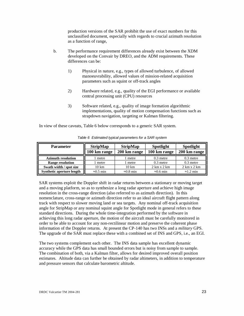
DRDC Valcartier TM 2004-281 23
production versions of the SAR prohibit the use of exact numbers for thisunclassified document, especially with regards to crucial azimuth resolutionas a function of range,
b. The performance requirement differences already exist between the XDMdeveloped on the Convair by DREO, and the ADM requirements. Thesedifferences can be:
1) Physical in nature, e.g., types of allowed turbulence, of allowedmanoeuvrability, allowed values of mission-related acquisitionparameters such as squint or off-track angles
2) Hardware related, e.g., quality of the EGI performance or availablecentral processing unit (CPU) resources
3) Software related, e.g., quality of image formation algorithmicimplementations, quality of motion compensation functions such asstrapdown navigation, targeting or Kalman filtering.
In view of these caveats, Table 6 below corresponds to a generic SAR system.
Table 6 Estimated typical parameters for a SAR system
Parameter StripMap StripMap Spotlight Spotlight100 km range 200 km range 100 km range 200 km range
Azimuth resolution 1 metre 1 metre 0.3 metre 0.3 metreRange resolution 1 metre 1 metre 0.3 metre 0.3 metre
Swath width / spot size 10 km 10 km 2 km x 2 km 2 km x 2 kmSynthetic aperture length ≈0.5 min ≈0.8 min ≈0.6 min ≈1.2 min
SAR systems exploit the Doppler shift in radar returns between a stationary or moving targetand a moving platform, so as to synthesize a long radar aperture and achieve high imageresolution in the cross-range direction (also referred to as azimuth direction). In thisnomenclature, cross-range or azimuth direction refer to an ideal aircraft flight pattern alongtrack with respect to slower moving land or sea targets. Any nominal off-track acquisitionangle for StripMap or any nominal squint angle for Spotlight mode in general refers to thesestandard directions. During the whole time-integration performed by the software inachieving this long radar aperture, the motion of the aircraft must be carefully monitored inorder to be able to account for any non-rectilinear motion and preserve the coherent phaseinformation of the Doppler returns. At present the CP-140 has two INSs and a military GPS.The upgrade of the SAR must replace these with a combined set of INS and GPS, i.e., an EGI.
The two systems complement each other. The INS data sample has excellent dynamicaccuracy while the GPS data has small bounded errors but is noisy from sample to sample.The combination of both, via a Kalman filter, allows for desired improved overall positionestimates. Altitude data can further be obtained by radar altimeters, in addition to temperatureand pressure sensors that calculate barometric altitude.
24 DRDC Valcartier TM 2004-281
High range resolution, of the order of the inverse of the FM chirp swept frequency bandwidth,is made possible by pulse compression of echoes of transmitted FM radar signals. Coherentintegration in the cross-range direction is implemented by the convolution of cross-range datawith matched response filters in the frequency domain. This allows extraction of image cross-range resolution proportional to the inverse of the Doppler bandwidth in the data window.
The three operating modes can be subdivided into two categories depending on whether:
a. The antenna beam is locked on a single position (Spotlight and RDP) whichis presumably the target of interest and for which focusing may be applied(thus the radar is steered to keep that point in the centre of the frame)
b. The antenna beam is held at a fixed angle relative to a straight-line flight thustraversing a ground swath during imaging (StripMap mode).
Whereas RDP provides a display of target cross-section as a function of range and Dopplerfrequency, Spotlight processing presents target radar cross-section as a function of the moreuseful linear range and cross-range coordinates. Strip-mapping does not correct for targetmotion and yields a continuous scrolling image of radar cross-section also as a function ofrange and cross-range, making it well suited to topographic mapping.
The operating mode specifics are discussed in the following sub-sections.
StripMapThe StripMap mode is mainly used for cartographic land imagery and coastal surveillance.Because the CP-140 may be operating in less than ideal conditions (bad weather, hostile landmass), the StripMap mode has the possibility of off-track acquisition of up to 60 degrees offnominal straight-ahead flight. Because it is usually operated for long periods of time duringterrain acquisition, the absence of standard radar returns for tracking purposes renders thetracking function of MSDF inoperative. The StripMap mode can be particularly useful inpeacekeeping operations (see next section).
According to the performance requirements specification (PRS) for the SSAR (SSAR ADMPRS, 1996) the StripMap mode algorithms provide range resolutions, which span theclassifications of:
• Super High (classified number)
• High (classified number)
• Medium (1.3 ± 0.2 m)
• Low (3.2 ± 0.3 m)
• Super Low (11.8 ± 0.5 m).

DRDC Valcartier TM 2004-281 25
The basic and enhanced azimuth resolutions are all classified and depend on the range. Theresulting imagery is usually treated by post-processing to form square pixels for display andrecording. The enhanced cross-range resolutions do not degrade as the off-track acquisitionangle increases. StripMap processing is real-time and done by so-called major frames. Theseare displayed in scrolling fashion to the operator.
Range Doppler Profiler (RDP)The RDP mode provides a movie to the operator in the Range vs. Doppler frequency domainfor target ID by the operator. The image seen is highly dependent on sea state, whichgenerates the motion whose Doppler motion provides the profile of interest. As such, only ahighly trained operator can evaluate the movie and identification usually takes minutes.
SpotlightA state-of-the-art SARP has to address the adaptive and non-adaptive sub-modes withalgorithms that are vastly different for two main reasons:
The Doppler motion of the target itself is used to generate the image (as in the adaptive modewhere ship roll, pitch and yaw depend on the Sea State) or not (as in the non-adaptive modewhere land targets are usually stationary)
The images that they aim to produce are deliberately optimised to focus on a moving isolatedpoint target (adaptive) or not (non-adaptive).
Therefore the image features and the attributes that will be obtained from either mode areexpected to be quite different for each mode.
Spotlight acquisition can be done at squint angles of +60 degrees (forward) to -30 degrees(backward) with respect to the perpendicular to the nominal flight plan.
According to the PRS for the SSAR, the Spotlight algorithms provide range resolutions thatspan the classifications of (SSAR ADM PRS, 1996):
• Super High (classified number)
• High (classified number)
• Medium (1.3 ± 0.2 m)
• Low (3.2 ± 0.3 m).
The basic and enhanced azimuth resolutions are all classified and depend on the range.Further, the enhanced cross-range resolutions degrade as the squint angle increases. Theresulting imagery is usually treated by post-processing to form square pixels for display andrecording.

26 DRDC Valcartier TM 2004-281
All types of spotlight processing are not real-time. The image processing time required isclassified data and depends on the requested azimuth resolution, but is of the order of aminute for the most demanding cases, as previously shown in Table 6. During imageprocessing, radar control can be switched back to normal mode or to other SAR modes.
The spotlight non-adaptive mode uses the step transform method to provide low-resolutionsub-apertures, which are then coherently summed to provide a high-resolution final image.The step transform method decomposes the full aperture into sub-apertures by convolving thereceived chirp signal with a sawtooth function. This mode is primarily used for stationaryland targets as no real attempt is made to track a selected target and centre it in the imagingframe apart from localizing strong returns to initiate the coherent superposition of targets. Itis often referred to as the land spot mode.
The spotlight adaptive mode also uses the step transform method to provide low-resolutionsub-apertures, which are then coherently summed to provide a high-resolution final image,and in addition performs several attempts to accurately track a selected target and centre it inthe imaging frame. It is used primarily for naval targets and, as such, is the primary mode forfusion for all maritime surveillance operations. It is often referred to as the sea spot mode.
Typical imagery from simulated data and from XDM flights will be analyzed and typicalattributes such as platform length, ship class, and ship category will be extracted. This isparticularly true of the spotlight mode. In view of the paucity of XDM imagery in spotlightadaptive mode, SAR image generation software will be used for image generation. Inparticular, the SARSIM simulator from DREO will be used to provide SAR imagery in thebroadside direction, for which it was designed.
The swath near range of the proposed SAR upgrade to the AN/APS-506 is within the roughupper limit of usability of the other imaging sensor, the FLIR, while the spot near range is atthe limit of the FLIR s operational capability. In this sense they are complementary, and theFLIR can take over where the SSAR leaves off, already initialized with the detailedcharacteristics of the target s previous position and any attribute information as to size orshape that can be obtained from a pattern recognition function of the images. This willconsiderably improve the FLIR s passive tracking and close-in ID capability at night. SARsystems exist that can provide a larger overlap in coverage in swath mode (near ranges asclose as 5 km are possible (Stacy et al., 1994) but none do in the crucial spotlight mode whena threat has been identified by illuminating it from some 100 kilometres away.
The conclusion is that real-time fusion of imaging sensors is only possible between the swathmode of the SAR and the FLIR and only in good environmental conditions. Complex imageregistration problems between the two imaging sensors can thus be avoided in all other cases.In fact, image registration will be ignored even when both imaging sensors can acquire atarget because the characteristics that could be used for registration, namely hot spots for theFLIR and strong radar scatterers for the SAR, are in general not co-located on the target.Fusion is therefore not performed on the images themselves, but through the complementaryattributes that they can provide. Any structural information that the imagery classifiers couldextract will be processed within the classifier itself, rather than forming part of the PDB. Thisapproach has several important advantages:

DRDC Valcartier TM 2004-281 27
1. the classifiers can be refined without affecting the PDB in any way;
2. the number of classifiers and their internal structure can vary, as required by theperformance that must be achieved;
3. the outputs of the classifiers themselves can be fused further, as will be discussed inthe second report of this series;
4. the PDB contains much less detailed information and is therefore easier to work with;
5. the classifiers can be viewed as post-processing black boxes, whose only requirementis that they provide outputs which are compatible with the PDB.
Therefore, the post-processing function on imaging data (or equivalently pre-processingfunction for fusion) will extract as many features as possible at longer ranges, e.g., platformlength, ship class and ship category, and use this attribute information to declare a possible listof platform IDs.
2.2.7 Characterization of CP-140 information sourcesAs was seen above, the present and foreseen sensors can be divided into three broad classesdepending on the type of input they provide to the MSDF function:
a. Attribute measurement oriented sensors (ESM, IFF, Link-11)
b. Imaging sensors (FLIR, SSAR)
c. Tracking sensors (radar, Link-11)
In Table 7 below, the inputs to MSDF that are available from the sensors are listed in bold,while the others that can be made available through further processing, either in an improvedversion of the sensor or in the data fusion function itself (provided digital data are given to itby the sensor), are in regular font. In the last column is a list of sensors that could be fused(but not necessarily should according to the text) with the given sensor. The capability ofpost-flight analysis and subsequent update of the MSDF databases provided by the FLIR andcamera exist but are not shown in the table. Also not shown is the possibility of an input toMSDF made by an operator who visually identifies a platform, and provides this informationto the fusion function via a keyboard entry.
Table 7 CP-140 suite of sensors and their inputs to a data fusion function
Sensors Input to MSDF1. AN/APS-506 Search radar range, bearing, speed, acceleration2. AN/ALR-502 ESM Bearing, emitter ID, platform ID3. AN/APX-502 IFF Range, bearing, allegiance4. OR-5008/AA FLIR Bearing, target attitude, platform ID5. Data link (Link-11) Other PU s tactical picture (position, velocity, ID, etc.)6. SAR Range, bearing, platform ID, image recording for post-flight analysis
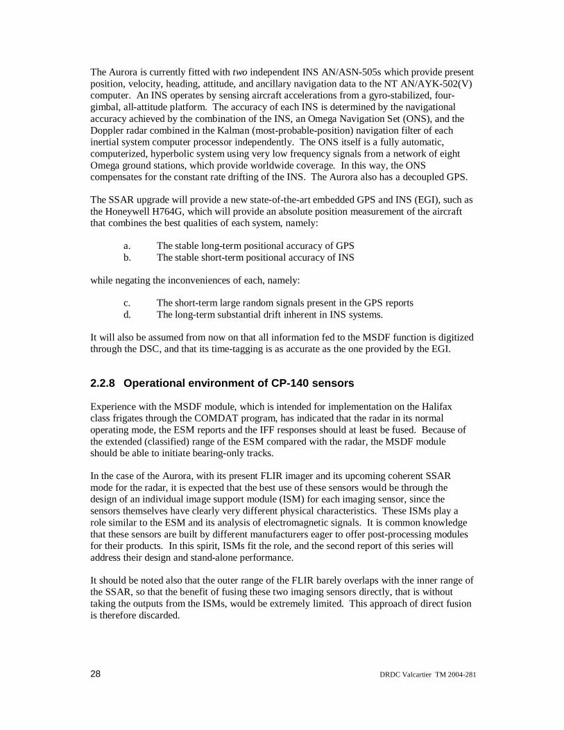
28 DRDC Valcartier TM 2004-281
The Aurora is currently fitted with two independent INS AN/ASN-505s which provide presentposition, velocity, heading, attitude, and ancillary navigation data to the NT AN/AYK-502(V)computer. An INS operates by sensing aircraft accelerations from a gyro-stabilized, four-gimbal, all-attitude platform. The accuracy of each INS is determined by the navigationalaccuracy achieved by the combination of the INS, an Omega Navigation Set (ONS), and theDoppler radar combined in the Kalman (most-probable-position) navigation filter of eachinertial system computer processor independently. The ONS itself is a fully automatic,computerized, hyperbolic system using very low frequency signals from a network of eightOmega ground stations, which provide worldwide coverage. In this way, the ONScompensates for the constant rate drifting of the INS. The Aurora also has a decoupled GPS.
The SSAR upgrade will provide a new state-of-the-art embedded GPS and INS (EGI), such asthe Honeywell H764G, which will provide an absolute position measurement of the aircraftthat combines the best qualities of each system, namely:
a. The stable long-term positional accuracy of GPSb. The stable short-term positional accuracy of INS
while negating the inconveniences of each, namely:
c. The short-term large random signals present in the GPS reportsd. The long-term substantial drift inherent in INS systems.
It will also be assumed from now on that all information fed to the MSDF function is digitizedthrough the DSC, and that its time-tagging is as accurate as the one provided by the EGI.
2.2.8 Operational environment of CP-140 sensors
Experience with the MSDF module, which is intended for implementation on the Halifaxclass frigates through the COMDAT program, has indicated that the radar in its normaloperating mode, the ESM reports and the IFF responses should at least be fused. Because ofthe extended (classified) range of the ESM compared with the radar, the MSDF moduleshould be able to initiate bearing-only tracks.
In the case of the Aurora, with its present FLIR imager and its upcoming coherent SSARmode for the radar, it is expected that the best use of these sensors would be through thedesign of an individual image support module (ISM) for each imaging sensor, since thesensors themselves have clearly very different physical characteristics. These ISMs play arole similar to the ESM and its analysis of electromagnetic signals. It is common knowledgethat these sensors are built by different manufacturers eager to offer post-processing modulesfor their products. In this spirit, ISMs fit the role, and the second report of this series willaddress their design and stand-alone performance.
It should be noted also that the outer range of the FLIR barely overlaps with the inner range ofthe SSAR, so that the benefit of fusing these two imaging sensors directly, that is withouttaking the outputs from the ISMs, would be extremely limited. This approach of direct fusionis therefore discarded.
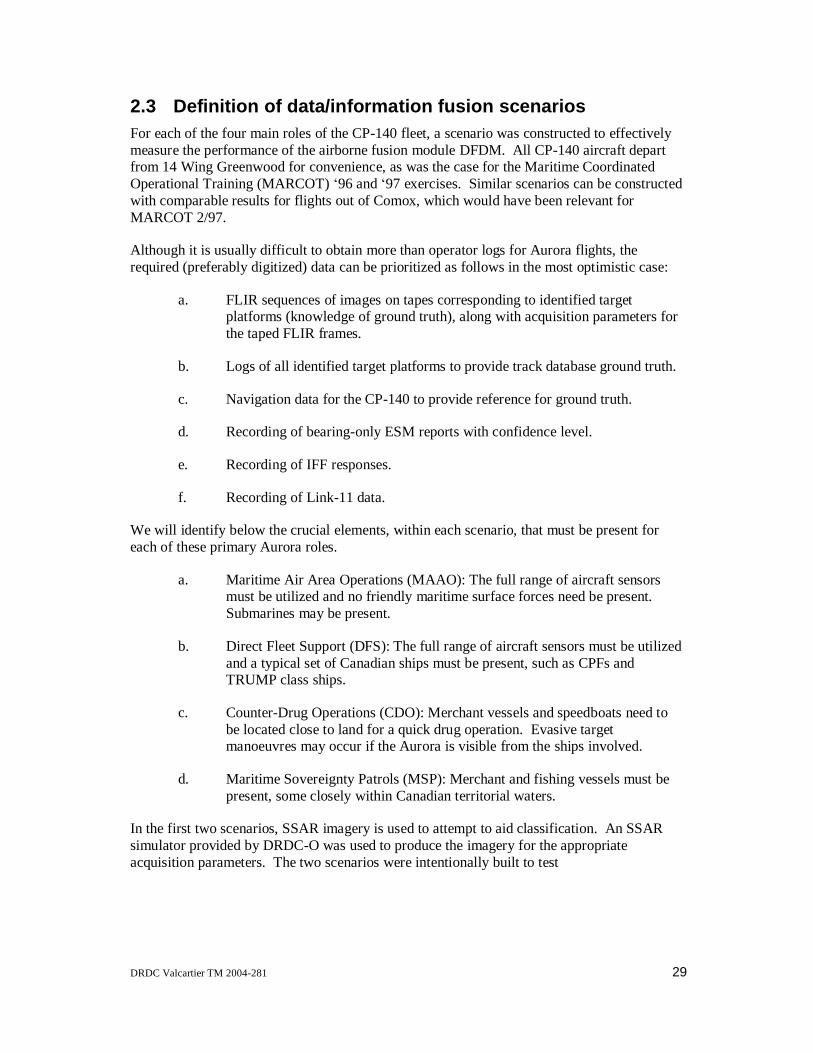
DRDC Valcartier TM 2004-281 29
2.3 Definition of data/information fusion scenariosFor each of the four main roles of the CP-140 fleet, a scenario was constructed to effectivelymeasure the performance of the airborne fusion module DFDM. All CP-140 aircraft departfrom 14 Wing Greenwood for convenience, as was the case for the Maritime CoordinatedOperational Training (MARCOT) 96 and 97 exercises. Similar scenarios can be constructedwith comparable results for flights out of Comox, which would have been relevant forMARCOT 2/97.
Although it is usually difficult to obtain more than operator logs for Aurora flights, therequired (preferably digitized) data can be prioritized as follows in the most optimistic case:
a. FLIR sequences of images on tapes corresponding to identified targetplatforms (knowledge of ground truth), along with acquisition parameters forthe taped FLIR frames.
b. Logs of all identified target platforms to provide track database ground truth.
c. Navigation data for the CP-140 to provide reference for ground truth.
d. Recording of bearing-only ESM reports with confidence level.
e. Recording of IFF responses.
f. Recording of Link-11 data.
We will identify below the crucial elements, within each scenario, that must be present foreach of these primary Aurora roles.
a. Maritime Air Area Operations (MAAO): The full range of aircraft sensorsmust be utilized and no friendly maritime surface forces need be present.Submarines may be present.
b. Direct Fleet Support (DFS): The full range of aircraft sensors must be utilizedand a typical set of Canadian ships must be present, such as CPFs andTRUMP class ships.
c. Counter-Drug Operations (CDO): Merchant vessels and speedboats need tobe located close to land for a quick drug operation. Evasive targetmanoeuvres may occur if the Aurora is visible from the ships involved.
d. Maritime Sovereignty Patrols (MSP): Merchant and fishing vessels must bepresent, some closely within Canadian territorial waters.
In the first two scenarios, SSAR imagery is used to attempt to aid classification. An SSARsimulator provided by DRDC-O was used to produce the imagery for the appropriateacquisition parameters. The two scenarios were intentionally built to test

30 DRDC Valcartier TM 2004-281
1. the limits of the association mechanism for ESM reports (with inter-ship distances atthe theoretical limit of discernability), leading to occasional mis-associations, and/orintentionally allowing ESM countermeasures on certain ships. This will becomeevident in the last of this series of three reports.
2. the performance of the SSAR ISM, by choosing ships whose imagery can bemisconstrued. This is achieved by having the scenario contain ships of unusual lengthfor their types, which fools the Bayesian classifier, which uses length distribution todetect ship type. This will become evident in the second and third of this series ofthree reports.
Both these scenarios were extensively studied and will show all of the good/bad features ofthe MSDF and ISM modules.
The third scenario uses some real SAR data, but not from a combatant ship. It was designedthinking that the Maritime Air Littoral Operations (MALO) Technology Demonstrator (TD)would be in place during or slightly after the present study, and would study several scenarios,including this one. Since it became evident that the MALO TD would be considerablydelayed, less emphasis was put on this scenario. In fact, the current scenario considered bythe MALO TD is a multi-faceted one off the Atlantic Coast, but with a definite militaryflavour, including a strong emphasis on situation and threat assessment and responsemanagement, as well as a tactics and doctrine study. It involves enemy submarines, as doesthe MAAO scenario, and a Canadian fleet of ships as does the DFS scenario, both of whichare described in the next sections.
It was also thought that some pictures of small fishing boats would be taken by DRDC-O, butthat turned out to be impossible with the delays in getting the SSAR on board the CP-140.Not even the Convair could fly to take such images during the present study.
Finally, the fourth scenario does not involve any SAR data since only merchant and smallships are involved. Again it was thought that some pictures of merchant ships would be takenby DRDC-O, or that further CAD models for the SSAR simulator would become available,but this turned out not to be the case, so little time was spent on this scenario.
2.3.1 SCENARIO 1: Maritime air area operationsThe location is NE of Greenwood past Prince Edward Island over the Gulf of St. Lawrence,and the duration of the simulated portion of the scenario is one hour during which the Auroratravels due north at an aircraft speed of 155 m/s (roughly 555 km/hr or 300 knots) and analtitude of 3 km (9,900 ft). Because DFDM can identify targets without a low altitude pass,the aircraft will maintain this altitude throughout the scenario.
Figure 1 shows a typical scenario with ships denoted by various types of circles:
a. Full circles represent ships entering the St. Lawrence River.
b. Open circles are ships either exiting the St. Lawrence River or in open seawith trajectories to be described further below.
c. Grey circle denotes a submarine.

DRDC Valcartier TM 2004-281 31
In addition, the rather large scale Figure 1 shows some air traffic denoted by lines of differenttypes:
a. The dashed line is the Aurora.
b. The full lines represent commercial aircraft.
Because aircraft identification and tracking is not a priority of the Aurora, the set of such airtargets has been kept to a minimum, just enough to show correct behaviour of the DFDMmodule.
Moncton
Greenwood
400
km
Figure 1. Air targets and rough locations of surface targets for maritime air area operations scenario
The air targets in Figure 1 consist of two transatlantic commercial aircraft bound for Canadianairports:
a. A Boeing 747 travelling at 450 knots and 33,000 feet (the altitude is reportedduring the scenario through an IFF response) in a general WSW directionbound for Montreal
b. A French Concorde headed for an airshow in the U.S., with a stopover inToronto, cruising at 1,000 knots and 50,000 feet (the altitude is also reportedduring the scenario through an IFF response) in a general WSW direction.

32 DRDC Valcartier TM 2004-281
There is also one inter-provincial commuter aircraft en route from Sydney (Newfoundland) toMoncton flying at 250 knots and a small private plane heading due west at 130 knots for alanding at Moncton, and therefore at low altitudes. These two aircraft serve a dual purpose inthis scenario:
a. Since the database does not contain examples of such aircraft, it is expectedthat the DFDM module will only be able to infer from their speed that theyare indeed air targets before any use of the IFF is made.
b. The scenario will have an IFF interrogation sent to the inter-provincialcommuter, which is left unanswered because of its faulty equipment to testthe robustness of the selected reasoning scheme.
Being so close to Canadian airspace in a non-wartime period, there are no hostile militaryaircraft in this scenario.
Figure 2 shows the surface target positions at the start of the one-hour scenario with respect tothe flight path of the Aurora as well as the velocity vectors (not to scale) for each of theplatforms. From west to east these are:
a. Two merchant ships heading for the Port of Montreal at 19 knots
b. Two merchant ships entering the Gulf of St. Lawrence, one heading due east,the other SSE at 21 knots
c. One small pleasure ship heading for the southern tip of the Magdalen Islandsat 12 knots
d. A Typhoon submarine cruising in surface mode heading due east for theMagdalen Islands at 25 knots, close to its maximum speed
e. A flotilla of three ships from the former USSR, heading NE for deeperwaters, one destroyer of Udaloy class, one cruiser of Kara class, and onefrigate of Mirka class, heading NE at a common speed of 30 knots, a commonvalue close to their maximum attainable speed (according to the values in thePDB).

DRDC Valcartier TM 2004-281 33
200
km
200 km
Figure 2. Detailed locations and directions of surface targets for maritime air area operationsscenario
The speeds have been chosen to exercise all of the speed intervals that result from thefuzzification of the speed attribute.
At appropriate times during the scenario, several ESM contacts are received for each hostilevessel, one such contact being incorrect for the platform (chosen arbitrarily to be the Udaloydestroyer), in order to test the robustness of the chosen reasoning scheme undercountermeasures (the chosen scheme will be the Dempster-Shafer algorithm explained in thesecond report of this series, whose performance will be demonstrated in the final third report).
The results from the DFDM module after the incorrect ESM report on the Udaloy areexpected to show increased ignorance about the possible platform identification for thattarget, a fact which would normally prompt an operator to image the vessel with the SAR inspotlight adaptive mode. Given that the imaged platform is roughly 100 km away, the imageacquisition time will be taken to be a modest 10 seconds for cross-range resolution of roughly3 metres (the true classified numbers have been replaced by the above, which can still bedeemed representative). Therefore the regular modes of the radar will be inoperative for 10seconds. The ISM module will report in short order an estimate of length, then ship type, thenship category (if identified as line).

34 DRDC Valcartier TM 2004-281
As soon as the operator has imaged the Udaloy, he or she will then in short order image theother two ships in the Russian convoy, the Kara cruiser and the Mirka frigate with roughly thesame acquisition parameters, since the Aurora s motion over such a short period of time is notvery significant. This will ensure that the simulated image acquisition, which is done viaSARSIM, is over the angular range where it can generate representative broadside imagery.
2.3.2 SCENARIO 2: Direct fleet supportThe location is 1,000 km due east of Greenwood in the mid-Atlantic where several CPFs andIroquois class ships are heading towards Europe, eventually to enter the Mediterranean andpass through the Suez Canal for support of NATO forces off Iraq. Aircraft speed is close tothe most economical cruising speed at 170 m/s (roughly 610 km/h or 330 knots) at an altitudeof 7.62 km (25,000 ft). The scenario length is three hours as indicated by the three doublearrows, each covering 610 km in length. Again the number of aircraft will be kept to a strictminimum:
a. A Boeing 747 is heading towards Boston at 35,000 feet and speed of 500knots and crosses the Aurora s flight path.
b. A CF-18 flies at 15,000 ft sub-sonically (600 knots or roughly Mach 0.93)parallel to the Aurora but 200 km to the north on a mission to a Europeanbase for deployment overseas.
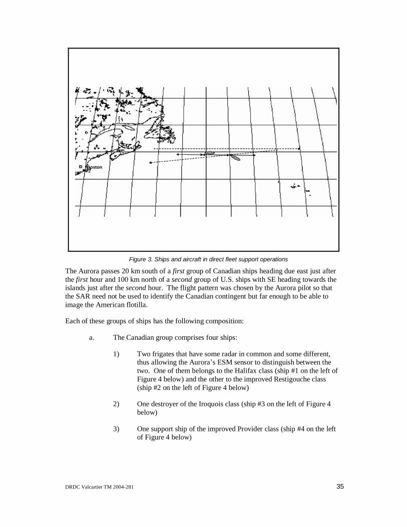
DRDC Valcartier TM 2004-281 35
Boston
Figure 3. Ships and aircraft in direct fleet support operations
The Aurora passes 20 km south of a first group of Canadian ships heading due east just afterthe first hour and 100 km north of a second group of U.S. ships with SE heading towards theislands just after the second hour. The flight pattern was chosen by the Aurora pilot so thatthe SAR need not be used to identify the Canadian contingent but far enough to be able toimage the American flotilla.
Each of these groups of ships has the following composition:
a. The Canadian group comprises four ships:
1) Two frigates that have some radar in common and some different,thus allowing the Aurora s ESM sensor to distinguish between thetwo. One of them belongs to the Halifax class (ship #1 on the left ofFigure 4 below) and the other to the improved Restigouche class(ship #2 on the left of Figure 4 below)
2) One destroyer of the Iroquois class (ship #3 on the left of Figure 4below)
3) One support ship of the improved Provider class (ship #4 on the leftof Figure 4 below)

36 DRDC Valcartier TM 2004-281
b. The American group comprises:
1) One Nimitz class carrier, the Theodore Roosevelt, since there areversions of the Nimitz that differ by their active sensor suite (ship #1on the right of Figure 4 below)
2) A cruiser of Ticonderoga class (ship #2 on the right of Figure 4below)
3) A cruiser of Virginia class (ship #3 on the right of Figure 4 below)
4) A destroyer of Coontz class (ship #4 on the right of Figure 4 below)
5) A destroyer of Spruance class (ship #5 on the right of Figure 4below)
6) A support ship of Sacramento class (ship #6 on the right of Figure 4below)
The Canadian frigates and the destroyer are cruising in formation at a common speed of 22knots (as seen in Figure 4 below after one hour of the scenario when the Aurora flies by). Thelongitudinal spacing between the combatant ships is ½ km and the transverse spacing is halfthat. This is illustrated in Figure 4.
The American ships are in formation at 26 knots with longitudinal spacing of 1 km andtransverse spacing half that (as seen in Figure 4 below after two hours of the scenario whenthe Aurora flies by). It need not be part of the convoy, because no threats have beenanticipated from intelligence reports, even if it is within range of some possible threats fromadvance bases of hostile intent.
The Aurora takes a low resolution spotlight adaptive image of three of the ships as itapproaches the fleet, while perpendicular to it, first the Coontz, then the Virginia and finallythe Ticonderoga. Acquisition parameters are similar to the previous scenario. As soon as theCoontz identifies that it is being continuously illuminated by the Aurora s radar (unknown tothe American fleet since the SSAR is assumed to have been only recently installed on theAurora), the Coontz reports it to the Nimitz, which then launches aircraft as detailed below,the first of which leaves when the Aurora is exactly perpendicular to the Nimitz.
Hence, during the fly-by of the Aurora, an F-15E Eagle is first launched, followed one minutelater by an F14A Tomcat. Two minutes later, one of the earliest F-22s to fly is launchedbefore anything can be ascertained about its active sensor suite or before its flight dynamicshave become documented well enough to be entered into the PDB. Their flight directions areslightly towards the Aurora (say ENE) for about 5 minutes at Mach 1.5 before they return tothe carrier, having got close enough to the CP-140 to inspect it and declare it friendly.
From IFF questioning and characteristic ESM report, the first two aircraft should be uniquelyidentified by DFDM but the F-22 should remain labelled as AIR due to its high speed. Inpractice, such a report should require a follow-up debriefing with the aim of improving the

DRDC Valcartier TM 2004-281 37
PDB s identification procedure, e.g., by denoting any achieved velocity or acceleration of theunknown aircraft. Furthermore, the launching of such specific aircraft from the Nimitz shouldallow an operator (or a higher level of fusion not attempted here) to correlate the airplanetypes with specific carriers (from intelligence sources of U.S. Navy shipyards).
1
2
4 3
0.5 km
CANADIAN FLEET
AMERICAN FLEET
4
5
6
3
1 km1
2
Figure 4. Canadian and American ship formations for direct fleet support operations
The quality of the tracks corresponding to the American contingent will be important in theAurora s Link-11 information provided to the trailing Canadian fleet.
2.3.3 SCENARIO 3: Counter-drug operationsThe location is near St. John s, Newfoundland, where a merchant ship headed for the port ofSaint John s is met by small speedboats for loading/unloading drugs. Both the merchantship s country of origin and the precise destination of the speedboats must be known forefficient arrest and later prosecution. Additional routine tracking and identification of typesnot tested in the previous two scenarios are also included.

38 DRDC Valcartier TM 2004-281
The duration of the scenario is one hour. In the first half, the Aurora performs routineoperations at a speed of 200 knots, altitude 5,000 feet and NE direction (straight flight), and inthe second half, it circles around the merchant vessel and the small boats located in a smallarea roughly 40 miles NE of St. John s, at the centre of the circle.
During the first portion of the flight, the Aurora flies within 100 km of a ship that it mustidentify through SAR imaging, and which is in reality the oceanography ship Quest headingdue east. This offers a pure test of the SAR image interpretation support module, the ISM,which deals exclusively with two-dimensional image data. Farther away, the Aurora mustalso identify a Canadian frigate of the St. Laurent class heading due north, which it mustdistinguish from other Canadian frigates through all of the frigate s radar emissions, whichmakes it different from frigates of the Ste. Croix class, for example. This provides a good testof the complementary electronic support module, the ESM, which deals exclusively with one-dimensional signal data. Both ships are identified with ellipses oriented according to theirdirection in Figure 6 below.
During the second circular portion of the flight, which is described in more detail below, theJahre-Vicking tanker is being used by seamen on board as a smuggling ship which isunloading drugs to three small speedboats, two of which are heading for the Northern BaySands Provincial Park and one towards the Lockston Path Provincial Park. These parksprovide good road access and are reasonably easy to reach by boat. The aim of the trackingmodule is to identify the correct number of boats heading for each park (by their rectilinearconstant velocity vector) and the time to intercept by local forces (by their absolute speed). Itshould also adequately estimate the tanker s speed so that the operator can ascertain ifnotification to the Canadian frigate nearby is warranted or not. The area where all drugsmuggling ships are located is indicated by the grey circle, which represents a circular area ofradius 15 km.

DRDC Valcartier TM 2004-281 39
NorthernBay Sands
St. John’s
Figure 5. Close-up of drug smuggling ships off St. John s
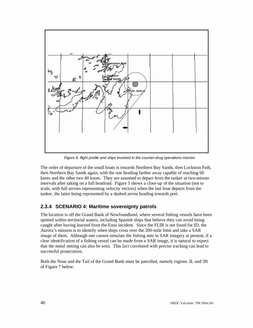
40 DRDC Valcartier TM 2004-281
Lockston Path
NorthernBay Sands
St. John’s
Figure 6. flight profile and ships involved in the counter-drug operations mission
The order of departure of the small boats is towards Northern Bay Sands, then Lockston Path,then Northern Bay Sands again, with the one heading farther away capable of reaching 60knots and the other two 40 knots. They are assumed to depart from the tanker at two-minuteintervals after taking on a full boatload. Figure 5 shows a close-up of the situation (not toscale, with full arrows representing velocity vectors) when the last boat departs from thetanker, the latter being represented by a dashed arrow heading towards port.
2.3.4 SCENARIO 4: Maritime sovereignty patrolsThe location is off the Grand Bank of Newfoundland, where several fishing vessels have beenspotted within territorial waters, including Spanish ships that believe they can avoid beingcaught after having learned from the Estai incident. Since the FLIR is not fused for ID, theAurora s mission is to identify when ships cross over the 200-mile limit and take a SARimage of them. Although one cannot simulate the fishing nets in SAR imagery at present, if aclear identification of a fishing vessel can be made from a SAR image, it is natural to expectthat the metal netting can also be seen. This fact correlated with precise tracking can lead tosuccessful prosecution.
Both the Nose and the Tail of the Grand Bank must be patrolled, namely regions 3L and 3Nof Figure 7 below.

DRDC Valcartier TM 2004-281 41
Figure 7. Fishing banks and management zones of the eastern seashore
A stylized magnified reproduction of Figure 7 is shown in Figure 8 with the Grand Bankrepresented as a dotted trapezoid, the 200-mile limit as a dashed semi-circular outline, and theAurora flight profile as a full circle (of approximately 150 km radius) over-flying both theNose and Tail of the Grand Bank as required by the mission. This circular flight path waschosen to nearly fly over St. John s in case the mission changed to a drug smugglingoperation similar to the previous scenario.

42 DRDC Valcartier TM 2004-281
NOSE
TAIL
Figure 8. Aurora flight profile for maritime sovereignty patrol mission
For this Aurora mission, the fishing boats are located in the rectangles shown in dash-dottedrectangles that overlap Canadian territorial waters in the NW parts of the Nose and Tail.

DRDC Valcartier TM 2004-281 43
3. Data/Information fusion process and architectureData/information fusion (Steinberg, Bowman & White, 1999) currently has the connotation ofencompassing at least four levels of fusion, the so-called Joint Directors of Laboratories (JDL)framework:
• Level 1: single object refinement should involve evidential reasoning over singleobject kinematics and attributes, towards the goal of obtaining the best platformID or at least some level of the taxonomy tree;
• Level 2: situation refinement, a.k.a. Situation and Threat Assessment (STA)should involve reasoning over groups of objects and proceed by higher inferencerules involving doctrinal and contextual information;
• Level 3: implication refinement should involve reasoning over plan alternatives tosuggest plan decisions;
• Level 4: process refinement should involve reasoning over own-ship andenvironmental conditions in order to perform better sensor management and thusclose the Observe, Orient, Decide, Act (OODA) loop. It should also refine thedata fusion process itself, taking into account the best algorithms, givencontextual information such as target density, clutter, expected target manoeuvres,etc.
There can also be an additional pre-processing step of raw data to provide single objectkinematics, images or attributes from a variety of sensors (Level 0), or a step which requiresthe human intervention in the loop to effect process refinement (a suggested Level 5). Theseancillary levels will not be discussed further.
This report (as well as the other two in this series) concentrates almost exclusively on Level 1single object refinement (mostly algorithmic) in a multi-sensor, multi-target environment, forboth positional (kinematic) and identity information fusion.
3.1 Multi-source data fusion architecture
This section is dedicated to showing the alternative architectures that can exist in current datafusion systems, depending on the availability of sensor data (contacts vs. tracks) and thelegacy architecture of the data exchange mechanisms that are accessible to the MSDF module.
3.1.1 Contact/Attribute level fusion
Fusion of contacts coming from each sensor theoretically gives the best results, since rawmeasurements are correlated in a central processing node. This assumes that the radar doesnot have an internal tracker, and that its raw contacts are available. This was not the case forany of the radar on the Halifax class frigates and is not currently the case on the Aurora.However, with the upgrade of the radar to a coherent mode by MacDonald Dettweiler, thismay become feasible.
44 DRDC Valcartier TM 2004-281
Attribute fusion refers to accumulating all the attributes relevant to a given platform beforedeciding on its ID.
This architecture is commonly referred to as a centralized architecture, corresponding to onlyone fusion node collecting all the contact (and attribute) data directly from each of thesensors, and performing all the processes appropriate for refining the position andidentification of each target (Waltz & Llinas, 1990). Another name for this same architectureis central-level architecture (Blackman, 1986).
3.1.2 Track/Declaration level fusion
Given that radar usually gives tracks, some decentralized or distributed fusion (at least theassociation and positional update portions) is already done within some sensors (Waltz &Llinas, 1990). Therefore another name for this same architecture is sensor-level architecture(Blackman, 1986).
In the case of the upgraded coherent radar, for example, a set of interesting tracks ismaintained for pointing the radar to acquire an image.
Declaration level fusion refers to each attribute generating a declaration, namely a list ofplatforms IDs that could have that attribute. If the attribute declaration is fuzzified, thedeclaration can contain many such lists. Typical attributes that can be fuzzified are usuallyrelated to physical quantities such as speed, acceleration and radar cross-section, as will bereviewed in the second of this series of three reports. Each successive different attributemeasurement is fused to refine the ID of the platform through some artificial intelligencemethod, such as Bayes reasoning or the Dempster-Shafer evidential reasoning method. Thesemethods will also be described at length in the second report of this series.
3.1.3 Hybrid approach
This corresponds to a mix of the two approaches above depending on the output of the sensorsat their current level of sophistication. For example, tracks provided by the current radars canbe converted into contact-like reports by adding random Gaussian noise, since tracks areKalman filter outputs, which have a smaller covariance than the original contacts that wereused in track formation. If one wishes to use contact-level algorithms within MSDF whenupdated tracks are coming from the radar, a small random noise can be added to the updatedtracks, which has the effect of de-correlating the contacts that originally made the track. Thiswas done for the naval radar on board the Halifax class frigates. It will also be assumed herethat the radar on board the Aurora has its tracks converted into contacts through thisprocedure. This solution allows the association of contacts with MSDF tracks via well-established contact-to-track gating and association mechanisms.
The FLIR and SSAR ISMs, for example, can provide a variety of types of declarations, someof which are not the ones corresponding to the fuzzified physical values described in section3.1.2. For example, ISMs can report target category (merchant or line combatant), type oftarget (frigates, destroyers, etc.), or even a list of types of targets with associated probabilities,or masses in the Dempster-Shafer sense, (e.g., 80% probability that the target is a frigate, 20%
DRDC Valcartier TM 2004-281 45
that it is a destroyer). These declarations can then be quite complex, and somewhat related,since, for example, a frigate is a subset of line combatant.
3.2 Multi-source data fusion process
3.2.1 Single platform positional fusion
This process evaluates the occurrence of the hypotheses obtained by data association andfuses the pairs of data (one sensor report to one existing track) according to somepredetermined criteria. It contains both the previous data association and the later stateestimation as its sub-functions. Its functional and performance requirements depend on thefusion architecture selected for MSDF.
In multiple scan operation, for example, in order to prevent computer resource overload, thisprocess must keep the tracks in this multi-hypotheses tracking (MHT) or multi-frameassociation (MFA) mechanism to a manageable level by the processes of pruning or merginghypotheses. It must also use to advantage the complementary nature of the sensors both intheir sensed data and their different environmental effectiveness, while, at the same time,preventing any one sensor from dominating its sensory inputs (which would effectively tendto reduce the sensor suite to a single sensor, obviating the need/use for MSDF), possibly byselecting sensor reports selectively.
The data fusion process is thus responsible for updating the track s state estimate and attributeestimate, possibly subject to criteria of the track management process, thus allowing for ahigher level kinematic behaviour assessment to be performed, as will be described further inthe following paragraphs.
This section describes the functionality of the positional fusion component, while section3.2.2 will describe the functionality of the identity fusion process.
Positional fusion mathematically refines the state of motion of a target track by fusing thetrack s previous state vector (position, speed and covariance) with new associated sensor data.In some cases, the target behaviour assessment process could suggest a specific model fortarget dynamics (constant acceleration, evasive manoeuvres of a known type for the targetID). Every time a new contact arrives, the state estimation problem can be formulated eitherin batch mode (fitting a track to a mathematical model form including the new contact) or bythe use of Kalman filters which process each new contact using only the informationcontained in the track s state vector and covariance matrix at the last contact time. Batchmethods being much more computer intensive, the usual choice is to perform the stateestimate through one or many Kalman filters, and this is the chosen method for the rest of thisreport. The output of a Kalman filter is an updated state vector and covariance matrix at thetime of the fused contact.
Positional fusion can be decomposed into three functions:
1. data registration,
2. data association, and
3. positional update,

46 DRDC Valcartier TM 2004-281
and can be subject to a track management process.
Data registration
The inputs to this sub-function should be sensor contacts and sensor tracks (depending on thefusion level chosen appropriately for each sensor) which are to be aligned with MSDF trackscoming from the track management (TM) function within MSDF. This process must performboth spatial and temporal alignment.
Temporal alignment performs a time propagation (or update ) of the state vector andcovariance matrix of the tracks to the sensor s reporting time. Spatial alignment performs anynecessary calculation to convert the contacts and tracks to the same geo-positional frame ofreference. Any spatial or temporal misalignment must be corrected within this function.Experience with the CPF DFDM has shown that time tagging of the sensors must be quiteaccurate (about a tenth of a second) for air targets. This is to be expected, since an aircrafttravelling near Mach 1 covers about 30 m in that time. However, since the Aurora will mainlybe tracking surface targets in most of its missions, accurate time tagging is expected to be lessof a constraint most of the time. The EGI on the Aurora does provide very accurate time-stamping of the Aurora s own position, since this is a crucial component of SAR processing.
The performance of the data alignment process depends on the quality of the assumptionsused to describe the kinematics of the target tracks. The performance can be consideredoptimal when the time update algorithms take into account not only the state estimate but alsothe target behaviour suggestion that resides in the TM database coming from previously fuseddata (for clarity of presentation, this link is not shown in Figure 2). Spatial alignment musttake into account all possible sources of noise (in the noise matrices of Kalman filters) andbiases, which could corrupt the alignment calculation. These sources can be local to theAurora (vibration, sensor calibration errors, faulty mounting, false true north) and thereforecomplicate alignment within the local air and surface fusion centre. They can also originateon PUs whose information must be aligned with the CP-140 s. Indeed, tactical datalinkinformation severely complicates registration problems due to totally new alignmentproblems, which can be substantial:
a. A translational spatial bias may exist between PUs, especially if their INSshave not been supplemented with a GPS. It is anticipated that all PUs willacquire GPSs before the end of AIMP.
b. A rotational spatial bias may exist between PUs if their true northdeterminations do not match.
c. A substantial time update step may have to be performed if the link has beendown for some time or the reporting PU has gone out of range for asignificant period.
d. The number of reported tracks may not match over an area of mutualcoverage, thus requiring a complicated optimization calculation to beperformed with the location of added fake tracks being an optimizingparameter.

DRDC Valcartier TM 2004-281 47
Biases in measurement data from radar on multiple platforms (a.k.a. registration errors) areknown to degrade track quality with respect to a single radar if sufficiently large. Thetechniques for registration of imaging data, say two pictures taken at different times withdifferent sensors and different viewpoints, are extremely complex to solve when dissimilar ornon-collocated sensors are being dealt with. In principle, this is feasible with identical andclosely-spaced sensors. Since the words "closely spaced" are relative to the expected targetrange, this is not a problem for the CP-140 except at very low altitudes when successive FLIRimages have to be registered. Also, since the FLIR and the SAR have little overlap in theranges they can cover, the problem of non-identical sensors does not apply. The most usefulapplication of registering several images, in the CP-140 context, should be the use of severalSAR frames to monitor target activity at long range.
Because the military problem of matching a target with a SAR image for identificationpurposes is closely related to several other scientific problems, several image registrationtechniques have evolved to the point of being increasingly automatic, efficient and robust.However, the registration problems of imaging with non-imaging data have not as yetreceived equally wide attention. These would affect all missions except air surveillance, sinceeither the FLIR or the SSAR are used (depending on target range) in conjunction with radarand other sensors.
Data associationIn general, the association schemes can be decomposed into (see below for acronyms):
• single-scan (e.g., nearest neighbour, JVC, PDA and JPDA) versus multi-scantechniques (MHT, MFA, N-scan back), and
• single-target (isolated) vs. multi-target (high density of targets with respect to theaccuracy of the sensor reporting the contacts to be associated with existingtracks).
In single-scan mode, nearest neighbour algorithms or variants thereof, such as the Jonker-Volgenant-Castanon (JVC) algorithm used in the Halifax class MSDF demonstration model,maximum likelihood estimators, and the probabilistic data association (PDA) for isolatedtargets or the joint probabilistic data association (JPDA) algorithms for dense targets, can beused (Bar-Shalom & Fortmann, 1988).
In the multiple scan mode, one usually employs multi-hypotheses tracking (MHT) algorithmsor multi-frame association (MFA) techniques, which create a set of statistical hypotheses thatmust be tested to determine whether the measured data correlates with the tracks (Bar-Shalom, 1990). To keep the algorithms operating in real time (since the hypotheses can growexponentially with the number of scans), pruning, merging of tracks into clusters and splittingof clusters into tracks are associated operations that restrict or generate hypotheses so as tomaintain a set of hypotheses that is of manageable proportions for the available computingpower (Blackman, 1986).
This is summarized in Table 8 below, where increasing row numbers go hand-in-hand withincreasing performance and computing cost. For practical computing cost reasons, theoptimal algorithm consisting in keeping all MHT hypotheses is never practically considered.
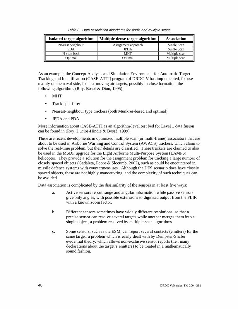
48 DRDC Valcartier TM 2004-281
Table 8 Data association algorithms for single and multiple scans
Isolated target algorithm Multiple dense target algorithm AssociationNearest neighbour Assignment approach Single Scan
PDA JPDA Single ScanN-scan back MHT Multiple scan
Optimal Optimal Multiple scan
As an example, the Concept Analysis and Simulation Environment for Automatic TargetTracking and Identification (CASE-ATTI) program of DRDC-V has implemented, for usemainly on the naval side, for fast-moving air targets, possibly in close formation, thefollowing algorithms (Roy, Bossé & Dion, 1995):
• MHT
• Track-split filter
• Nearest-neighbour type trackers (both Munkres-based and optimal)
• JPDA and PDA
More information about CASE-ATTI as an algorithm-level test bed for Level 1 data fusioncan be found in (Roy, Duclos-Hindié & Bossé, 1999).
There are recent developments in optimized multiple scan (or multi-frame) associators that areabout to be used in Airborne Warning and Control System (AWACS) trackers, which claim tosolve the real-time problem, but their details are classified. These trackers are claimed to alsobe used in the MSDF upgrade for the Light Airborne Multi-Purpose System (LAMPS)helicopter. They provide a solution for the assignment problem for tracking a large number ofclosely spaced objects (Gadaleta, Poore & Slocumb, 2002), such as could be encountered inmissile defence systems with countermeasures. Although the DFS scenario does have closelyspaced objects, these are not highly manoeuvring, and the complexity of such techniques canbe avoided.
Data association is complicated by the dissimilarity of the sensors in at least five ways:
a. Active sensors report range and angular information while passive sensorsgive only angles, with possible extensions to digitized output from the FLIRwith a known zoom factor.
b. Different sensors sometimes have widely different resolutions, so that aprecise sensor can resolve several targets while another merges them into asingle object, a problem resolved by multiple-scan algorithms.
c. Some sensors, such as the ESM, can report several contacts (emitters) for thesame target, a problem which is easily dealt with by Dempster-Shaferevidential theory, which allows non-exclusive sensor reports (i.e., manydeclarations about the target s emitters) to be treated in a mathematicallysound fashion.

DRDC Valcartier TM 2004-281 49
d. Association of imaging and non-imaging data is an emerging science, even atthe contact level, but is rather straightforward when the imaging sensor iscued to an MSDF track generated from information mostly coming from thenon-imaging sensors. More details will be found in the next two reports ofthis series, with imaging sensor ISMs designed, implemented and tested (instand-alone fashion) in the second report, and the performance of jointlyfusing imaging and non-imaging information demonstrated in the third (andlast) report.
e. Some further image processing from imaging sensors may extract severalfeatures to be associated with tracks at a later time (thereby complicating thedata alignment problem), e.g., a missile launch may be seen by the FLIR viathe missile s plume before the radar forms a recognized track for the launchedmissile (usually the radar will initiate a track after the first contact, declare ittentative after a few more contacts, and then promote it to a recognized trackwhen the track covariance is relatively stable). In an extreme case, the shapeof a missile can be seen by the SAR before launch, e.g., if the missile islaunched from a ground station, which could affect subsequent data initiationand provide a quick possible ID, and later data association and filtering, sincean ID from the SAR could suggest flight characteristics. If the expected flightpatterns are complex, more sophisticated data association and filtering maybe required.
Positional updateThis process evaluates the occurrence of the hypotheses obtained by data association andfuses the pairs of data (one sensor report to one existing track) according to somepredetermined criteria. It contains both the previous data association and the later stateestimation as its sub-functions. Its functional and performance requirements depend on thefusion architecture selected for MSDF. In multiple-scan operation, for example, in order toprevent computer resource overload, this process must keep the MHT tracks to a manageablelevel by the processes of pruning or merging hypotheses. It must also use to advantage thecomplementary nature of the sensors both in their sensed data and their differentenvironmental effectiveness, while, at the same time, preventing any one sensor fromdominating its sensory inputs (which would effectively tend to reduce the sensor suite to asingle sensor, obviating the need/use for MSDF), possibly by selecting sensor reportsselectively. The data fusion process is thus responsible for updating the track s state estimateand attribute estimate, possibly subject to criteria of the track management process, thusallowing for higher level kinematic behaviour assessment to be performed, as will bedescribed further in the following paragraphs.
Positional fusion mathematically refines the state of motion of a target track by fusing thetrack s previous state vector (position, speed and covariance) with new associated sensor data.In some cases, the target behaviour assessment process could suggest a specific model fortarget dynamics (constant acceleration, evasive manoeuvres of a known type for the targetID). Every time a new contact arrives, the state estimation problem can be formulated eitherin batch mode (fitting a track to a mathematical model form including the new contact) or bythe use of Kalman filters, which process each new contact using only the information

50 DRDC Valcartier TM 2004-281
contained in the track s state vector and covariance matrix at the last contact time. Batchmethods being much more computer intensive, the usual choice is to perform the stateestimate through one or many Kalman filters, and this is the chosen method for the rest of thisreport. The output of a Kalman filter is an updated state vector and covariance matrix at thetime of the fused contact.
Track management processThis process must continually update the positional and attribute information obtained aftereach new sensor report has been fused. The MSDF track database must be optimized tomatch the available memory resources of the processors. It must decide how to initiate newtracks (particularly initial speed and covariance), when to update existing tracks (particularlyin the attribute sector), when to promote tracks depending on threat level and when torecommend deletion (i.e., request killing ) of old tracks for which no contacts have beenassociated for a substantial period of time.
Since an important goal of fusion is to provide a final unique target ID for each track, themost probable list of candidate platform IDs should be continuously updated, along with thebelief in that ID. Depending on memory availability, alternative lists of platform IDs shouldbe kept (eight were kept in the CPF DFDM). In addition, some generic information about thetrack should be updated, such as possible allegiance, nationality, anticipated threat level, etc.,along with supports for these assertions. During the DFDM for the CPF, it was found thattrack information should also contain enough past contact history to allow a judgement as towhether a new sensor report should be fused or should be discarded because it is too similar topreviously reported contacts. This is especially true of attribute information, which has atendency to be redundant. For example, a target that has maintained cruising speed along astraight-line trajectory has a definite value for the speed attribute that should not be fusedevery time a new radar contact updates the velocity information in the state estimationprocess. In this case, only changes in speed and the time frame in which this is performed(which gives an idea of the acceleration) really provide new information that must be fused.The same is expected of the CP-140 s sensors. The search radar s report frequency, thus thetracker s speed attribute determination, far exceeds the rate of ESM or IFF reports, whichcontain more selective (and thus more useful) information about the platform ID.
3.2.2 Single platform identity information fusion
Given the attributes measured by the sensors, and an estimate of the confidence level for thatmeasurement, two distinct approaches are possible:
• Bayesian approach, where the confidence level is split amongst all platforms whichcan have that attribute, given an estimate of the a priori distribution of theseplatforms for any given mission. In the absence of any a priori distributioninformation, the confidence level is evenly split, which can result in many platformshaving a very small probability. The reasoning is always on individual platforms, sothe maximum number of probabilities to calculate is equal to the maximum number ofplatforms N.
DRDC Valcartier TM 2004-281 51
• Dempster-Shafer approach (Dempster, 1967, and Shafer, 1976), where the confidencelevel is applied as a whole to the set of platforms which can have that attribute.Successive fusion steps result in an intersection of sets, which can lead to 2N
ensembles that will have some confidence (called basic probability assignment ormass). To avoid exponentially growing complexity, an approximation or truncationscheme must be implemented to keep the method tractable in real time.
Both of these algorithms are detailed in the second report of this series.
3.2.3 Multi-platform positional/identity fusionThis series of three reports concerns only the single-platform case. A separate report will dealwith data fusion between collaborating platforms (DFCP) and the communication protocolsthat must be ensured to prevent data incest (a.k.a. data looping), which occurs when sensorson board different platforms measure the same object (having the same process noise, forexample). In that report, many different techniques for preventing data incest on thepositional side will be examined and evaluated.
However, data incest for ID is particularly difficult to handle, except if one keeps the pedigreeof the ID information that is being fused, through some historical record of the origin of thereports leading to the current ID. There have been some attempts at standardization of thisissue of ID processing and the possibility of incest, such as the ones described in STANAG4162, particularly concerning allegiance determination from Bayesian a priori probabilitydistributions of various kinds. STANAG 4162 is not universally recognized, nor implementedto our knowledge.
52 DRDC Valcartier TM 2004-281
4. A priori Information
4.1 Databases
4.1.1 Baseline platform databaseThis section describes the structure of a PDB that is used by a target identification algorithmthat applies sensor fusion of attribute data. Theoretically, a PDB is a listing of all the surface,sub-surface, air and land platforms that are the potential identity of the targets detected andreported by the sensors or the information sources of a military surveillance system. Here theword surveillance takes a general sense, which includes also tracking, detecting, monitoring,etc. In practice, the PDB that was generated for this study does not incorporate land targets,mainly because the scenarios do not contain them. The platforms are described in terms ofthe parameters that are measured and seen by the sensors.
There are also two related linked lists,
• the geo-political list (GPL), which lists the attribute data that are assessed by thecommunications intelligence (COMINT) sensor for each country or organization inthe world, and
• the emitter name list (ENL), which includes the name and class of all radio emittersources that can be detected by the electronic intelligence (ELINT) sensor.
These lists are described in their respective subsections.
Each field present in the PDB is described in the next subsection. Table 9 below provides aquick outline of the format of the fields of the PDB. The first column shows the field namewith a brief description. The second column indicates the physical units. The accelerationACC is given in m/s2. The general practice in the aviation industry is to put this unit in termsof g, the average sea-level gravitational acceleration, so the conversion factor used here was g= 10 m/s2, which is sufficiently accurate. The radar cross-section (RCS) variables are given insquare decimeters (1 dm2 = 0.01 m2). The speed variable is given in knots (1 knot = 1853m/hr). The third column indicates the software variable type. The last column indicates thedomain value. The valid numbers are the values that have the interpretation of the field withtheir units. The other values are reserved for information and future utilization.
Examples of those reserved values are the maximum and the maximum minus one value. Forall the integer type fields the maximum value is reserved to indicate "undetermined" or"unknown". This reserved value, which is always in the form of 9, 99, 999, and so on,indicates that a valid value exists but has not been obtained. The maximum minus one valueis an indication that the field, except the rotating part field, is not applicable to the platform.This reserved value is always equal to one integer less than the maximum value permitted bythe format, namely, 8, 98, 998, and so on. Note that the acronyms for the field names are notlisted in the Acronyms section at the end of this report.
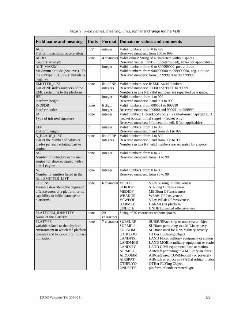
DRDC Valcartier TM 2004-281 53
Table 9 Field names, meaning, units, format and range for the PDB
Field name and meaning Units Format Domain or values and commentsACCPlatform maximum acceleration
m/s2 integer Valid numbers: from 0 to 499Reserved numbers: from 500 to 999
ACROCountry acronym
none 4 charactersValid values: String of 4 characters without spaces.Reserved values: UNDE (undetermined), N/A-(not applicable).
ALT_MAXIMMaximum altitude (sea level). Forthe subtype SUBSURF altitude isnegative
m integer Valid numbers: from 0 to 899999999, pos. altitudeValid numbers: from 900000000 to 999999000, neg. altitudeReserved numbers: from 999999001 to 999999999
EMITTER_LISTList of NE index numbers of theEML pertaining to the platform
none list of NEintegers
Valid numbers: see INEML valid numbersReserved numbers: 00000 and 99900 to 99999Numbers in this NE valid numbers are separated by a space.
HEIPlatform height
m integer Valid numbers: from 1 to 990Reserved numbers: 0 and 991 to 999
INDPDBPlatform index
none 6 digitinteger
Valid numbers: from 000001 to 999950Reserved numbers: 000000 and 999951 to 999999
IRType of infrared signature
none integer Valid number: 1 (blackbody only), 2 (afterburner capability), 3(rocket booster initial stage) 4 (rocket only)Reserved numbers: 9 (undetermined), 8 (not applicable).
LENPlatform length
m integer Valid numbers: from 1 to 990Reserved numbers: 0 and from 991 to 999
N_BLADE_LISTList of the number of palms orblades per each rotating part orengine
none list of RPintegers
Valid numbers: from 1 to 899Reserved numbers: 0 and from 900 to 999Numbers in this RP valid numbers are separated by a space.
NCNumber of cylinders in the mainengine for ships equipped with adiesel engine
none integer Valid numbers: from 0 to 50Reserved numbers: from 51 to 99
NENumber of emitters listed in thefield EMITTER_LIST
none integer Valid numbers: from 0 to 89Reserved numbers: from 90 to 99
OFFENSVariable describing the degree ofoffensiveness of a platform or itscapability to inflict damage toplatforms
none 6 charactersVESTOF VEry STrong OFfensivenessSTROOF STROng OFfensivenessMEDIOF MEDIum OFfensivenessWEAKOF WEAK OFfensivenessVEWEOF VEry WEak OFfensivenessHARMLE HARMLEss platformUNDETE UNDETErmined offensiveness
PLATFORM_IDENTITYName of the platform
none 20characters
String of 20 characters without spaces
PLATYPEvariable related to the physicalenvironment in which the platformoperates and to its civil or militaryutilization
none 7 charactersSUBSURF SUBSURFace ship or underwater objectSURMILI SURface pertaining to a MILItary navySURNOMI SURface used for Non-MIlitary activityOTHFLOO OTHer FLOating ObjectLANDFIX LAND FIXed military equipment or stationLANDMOB LAND MOBile military equipment or stationLANDCIV LAND CIVil equipment, base or stationAIRMILI AIRcraft pertaining to a MILItary air forceAIRCOMM AIRcraft used COMMercially or privatelyAIRSPAT AIRcraft or object in SPATial orbital motionOTHFLYO OTHer FLYing ObjectUNDETER platform of undetermined type
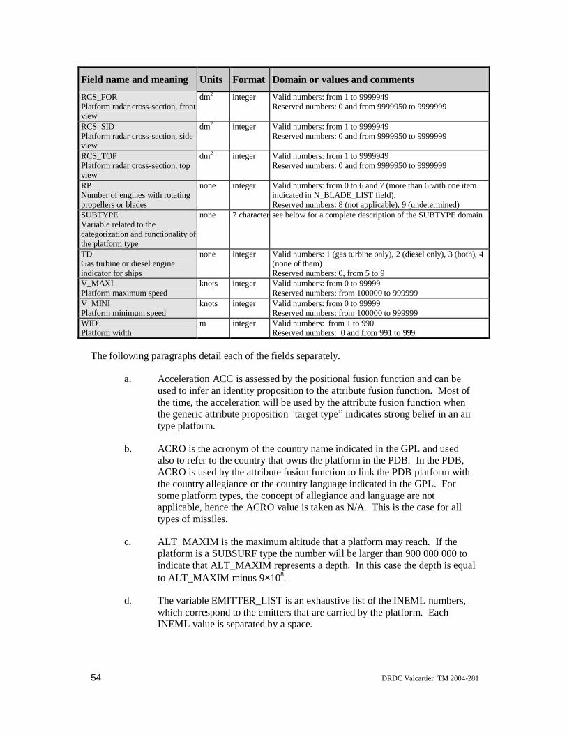
54 DRDC Valcartier TM 2004-281
Field name and meaning Units Format Domain or values and commentsRCS_FORPlatform radar cross-section, frontview
dm2 integer Valid numbers: from 1 to 9999949Reserved numbers: 0 and from 9999950 to 9999999
RCS_SIDPlatform radar cross-section, sideview
dm2 integer Valid numbers: from 1 to 9999949Reserved numbers: 0 and from 9999950 to 9999999
RCS_TOPPlatform radar cross-section, topview
dm2 integer Valid numbers: from 1 to 9999949Reserved numbers: 0 and from 9999950 to 9999999
RPNumber of engines with rotatingpropellers or blades
none integer Valid numbers: from 0 to 6 and 7 (more than 6 with one itemindicated in N_BLADE_LIST field).Reserved numbers: 8 (not applicable), 9 (undetermined)
SUBTYPEVariable related to thecategorization and functionality ofthe platform type
none 7 character see below for a complete description of the SUBTYPE domain
TDGas turbine or diesel engineindicator for ships
none integer Valid numbers: 1 (gas turbine only), 2 (diesel only), 3 (both), 4(none of them)Reserved numbers: 0, from 5 to 9
V_MAXIPlatform maximum speed
knots integer Valid numbers: from 0 to 99999Reserved numbers: from 100000 to 999999
V_MINIPlatform minimum speed
knots integer Valid numbers: from 0 to 99999Reserved numbers: from 100000 to 999999
WIDPlatform width
m integer Valid numbers: from 1 to 990Reserved numbers: 0 and from 991 to 999
The following paragraphs detail each of the fields separately.
a. Acceleration ACC is assessed by the positional fusion function and can beused to infer an identity proposition to the attribute fusion function. Most ofthe time, the acceleration will be used by the attribute fusion function whenthe generic attribute proposition "target type indicates strong belief in an airtype platform.
b. ACRO is the acronym of the country name indicated in the GPL and usedalso to refer to the country that owns the platform in the PDB. In the PDB,ACRO is used by the attribute fusion function to link the PDB platform withthe country allegiance or the country language indicated in the GPL. Forsome platform types, the concept of allegiance and language are notapplicable, hence the ACRO value is taken as N/A. This is the case for alltypes of missiles.
c. ALT_MAXIM is the maximum altitude that a platform may reach. If theplatform is a SUBSURF type the number will be larger than 900 000 000 toindicate that ALT_MAXIM represents a depth. In this case the depth is equalto ALT_MAXIM minus 9×10⁸.
d. The variable EMITTER_LIST is an exhaustive list of the INEML numbers,which correspond to the emitters that are carried by the platform. EachINEML value is separated by a space.

DRDC Valcartier TM 2004-281 55
e. HEI is the physical height of the platform in its natural vertical axis. For thesurface type, this corresponds to the average height between the bridge andthe water line. This field represents a variable that should be interpreted as afuzzy logic variable by the proposition interpreter of an attribute fusionfunction.
f. INDPDB is the index number of the platform in the PDB.
g. IR is a field associated with the infrared signature of the platform as seen byan infrared sensor system and its operator.
h. LEN is the physical length of the platform in its natural longitudinal axis.This field represents a variable that should be interpreted as a fuzzy logicvariable by the proposition interpreter of an attribute fusion function.
i. NUM_BLADE_LIST provides a list of the number of palms or blades pereach rotating part or engine. The number of palms or blades is detected by asonar for surface and sub-surface types and by a high frequency radar in thecase of an air target.
j. NC is the number of cylinders in the engine of a ship equipped with a dieselengine. This number can be assessed by a sonar operator.
k. NE is the number of different emitters present on the platform as provided inthe field EMITTER_LIST.
l. OFFENS is a field related to the degree of lethality of the platform. This fieldis not a measured variable and is used by the proposition management task ofthe attribute function in the selection of the reported identity in situations ofhigh ambiguity. The character values that the variable OFFENS can take arelisted in Table 9 above, together with a justification for its acronym.
m. PLATFORM_IDENTITY is the name of the platform (in characters).
n. PLATYPE forms the first level of platform classification used in this PDB.The platform type is related to the platform military utilization or itsoperating environment. Most sensor systems are capable of detecting broaderlevel types such as air or surface. In this case those broader levels are thesum of a group of PLATYPE values in the PDB. The character values thatPLATYPE can take are listed in Table 9 above, as well a justification for itsacronym.
o. RCS_FOR, RCS_SID, RCS_TOP correspond to the RCS of the platform seenfrom the front, the side and the top view, respectively. These fields representvariables that should be interpreted as fuzzy logic variables by the propositioninterpreter of an attribute fusion function. Due to the absence of informationabout these quantities, the data are extracted from the following temporaryrules of Table 10 below, which only take into account the fact that metallic

56 DRDC Valcartier TM 2004-281
objects offer strong radar backscatter when compared with the geometricalcross-section, i.e., the one that can be evaluated by the outline of the platformas deduced by the ISM, for example, or by a visual sighting by an operator.
Table 10 Temporary rules for generating radar cross-sections from platform dimensions
PLATYPE/SUBTYPE RCS_FOR RCS_SID RCS_TOP
Ships HEI × WID × 100 HEI × LEN × 100 LEN × WID × 100
Submarines 2500 × 100 250 LEN × WID × 100
Aircraft HEI × WID ÷ 8 × 100 HEI × LEN ÷ 4 × 100 LEN × WID ÷ 4 × 100
Missiles HEI × WID × 100 HEI × LEN × 100 LEN × WID × 100
The measured RCS σ can be deduced from the single-pulse radar returnsignal-to-noise ratio (SNR), as provided for example by the CASE-ATTIsimulator, according to an equation similar to (McCandless & Mango, 1997)
S N PGR R
AL k T
/ =4 4
12 2π
σπ β
where P is the pulse power, G the antenna transmitter gain, R the target range,A the effective receive antenna aperture area, L radar system losses (includingatmospheric losses), k Boltzmann s constant, β the radar bandwidth, and Tthe system noise temperature in Kelvin (such that kT is an energy). In thisequation, the first term represents power impinging on the target, the secondterm the amount reflected, the third the amount geometrically collected at thereceiving antenna, and the last term, the amount detected electronically.
The important fact to notice is the R-4 dependence between S/N and σ, allother things being radar characteristic constants or assumed constants as afunction of time. Therefore, in addition to the direct relationship betweenthese quantities, low S/N values should be interpreted as small values of σwith a high associated error. Conversely, large S/N values have smallerrelative errors associated with them. One should note that, during the SARintegration time, the coherent data collection mechanism changes thisrelationship to a lesser R-3 dependence, and that multi-look processing resultsin an intermediate R dependence (McCandless & Mango, 1997).
It should also be clear that the optimal method of deducing an RCS valueshould take into account the three-dimensional geometry of radar returnacquisition since the measured RCS (a single time-tagged measurement) willbe a linear superposition of RCS_FOR, RCS_SID and RCS_TOP, accordingto how much the normal to those respective surfaces can be projected ontothe line-of-sight (LOS).

DRDC Valcartier TM 2004-281 57
Since it is impossible to induce numerical values for three independentquantities (the three RCSs) without taking into account three sufficientlyindependent measures of the dependent variable, the S/N ratio would have tobe monitored over long periods of time, sufficiently long for the target-to-Aurora aspect to change significantly. During this time, even a crudeestimate of the most relevant of the three RCSs can lead to a much betteridentification through MSDF than waiting for three values of RCS to beaccumulated before being sent to MSDF. Therefore, fusion should only beattempted using a fuzzified value of the leading RCS value, namely thatdirection which projects the most onto the LOS.
p. RP indicates the number of rotating parts such as propellers or blades that canbe detected or assessed by the radar and its operator. Except if the value is 7,RP indicates how many items are indicated in the field N_BLADE_LIST. IfRP is equal to 7, only one number is indicated. It is assumed in this case thatthe platform has more than six rotating engines, which have an equal numberof blades.
q. SUBTYPE provides a sub-classification of the platform type, and is tooinvolved to be described here.
r. TD is a gas turbine or diesel engine indicator for the platform ships. Thisindicator applies to information that is deduced by the passive sonar and itsoperator. There are four valid values for this field: 1 for the platformspropelled by only gas turbine engines, 2 for the platforms propelled by onlydiesel engines (this leads to a valid value in the field NC), 3 for both), and 4for none
s. V_MAXI gives the maximum value of the platform speed while V_MINIgives the minimum value of the platform speed.
t. WID provides the physical width of the platform in its natural transverse axis.This field represents a variable that should be interpreted as a fuzzy logicvariable by the proposition interpreter of an attribute fusion function.
The ENL is linked to the PDB through the INEML numbers contained in the emitter list of thePDB.
Table 11 below provides a quick outline of the format of the fields of the ENL in a formatsimilar to that used for the PDB. Note that the first column shows the field name with a briefdescription, the second column indicates the physical units, the third column indicates thesoftware variable type, while the last column indicates the domain value.
Table 11 Field names, meaning, units, format and range for the ENL
Field name and meaning Units Format Domain or values and commentsEMITTER_IDENTITYName of the emitter
none 1 to 20 characters String of 20 characters or less without spaces

58 DRDC Valcartier TM 2004-281
Field name and meaning Units Format Domain or values and commentsGENFUNCVariable related to the emittertype and its utilization
none 7 characters See below for a complete description of theGENFUNC domain.
INEMLIndex in the EML
none 6 digits integer Valid numbers: from 00001 to 99949Reserved numbers: 00000, from 99950 to 99999
The following paragraphs detail each of the fields separately.
a. The variable EMITTER_IDENTITY is just the name of the emitter in theENL. This field corresponds to an ESM variable where many emitter namesmay be provided by this sensor (or its operator) for a single detection due toambiguity in the information resolution. For the moment it is not surewhether the name or the INEML number will be provided.
b. The generic variable GENFUNC provides the classification for the emittersof the ENL that correspond to the functionality of an emitter or to itsenvironment. Table 12 below lists all the values of the field GENFUNCtogether with a justification for its acronym. The ESM sensor may provide ageneric type of emitter when it is impossible for this sensor to provide a listof specific emitter names.
c. INEML is the index number of the emitter in the ENL.
Table 12 Values for the GENFUNC parameter of the emitter
GENERIC FUNCTION
ATCMAIN Air Traffic Control MAIN radar NAV2DSU NAVal 2D SUrveillance radar
AIRMULT AIR MULTi-purpose radar NAV3DSU NAVal 3D SUrveillance radar
AIRNAVI AIR NAVIgation radar NAVNAVI NAVal NAVIgation radar
AIRFICO AIR FIre COntrol radar NAVFICO NAVal FIre COntrol radar
AIRECMS AIR Electronic Countermeasure System NAVECMS NAVal ECM System
IFFINRE IFF INterrogator or Responder ATCGCCA ATC Ground/Carrier Control App.
MISHORA MISsile HOming Radar LANDSUR LAND SURveillance radar
SUBSUSU SUB-SUrface SUrveillance radar LANADSR LANd Air Defence System Radar
MISCELL other MISCELLaneous function UNDETER function UNDETERmined
The GPL is linked to the PDB through the platform acronym contained in the variable ACRO.

DRDC Valcartier TM 2004-281 59
Table 13 below provides a quick outline of the format of the fields of the GPL in a formatsimilar to that used for the PDB. Note that the first column shows the field name with a briefdescription, the second column indicates the physical units, the third column indicates thesoftware variable type, while the last column indicates the domain value.
Table 13 Field names, meaning, format and range for the GPL
Field name andmeaning
Format Domain or values and comments
ACROCountry acronym
4 characters Valid values: String of 4 characters without spaces.Reserved values: UNDE (undetermined), N/A-(not applicable)
ALLEGIAAllegiance of the country
7 characters NOTDECL (not declared) NEUTRAL (declared as neutral)FRIENDL (declared as friendly) HOSTILE (declared as hostile)NATO (belonging to NATO force for mission)
COUNTRY_NAMEName of the country
1 to 20 characters String of 20 characters or less without spaces.
NLNumber of languages in use onthis platform
integer Valid numbers: from 1 to 5Reserved numbers: 0 and from 6 to 9
LANGUAGE_LISTList of NL names of languages
list of NL 1 to 20characters
String of 20 characters or less without spaces. Values in the list of NLvalues are separated by a blank space.
The following paragraphs detail each of the fields separately.
a. The variable ALLEGIA provides the allegiance of the country under theacronym ACRO. Allegiance is a concept applicable to a country, not aplatform. The value "FRIEND" is measured by the IFF while the othervalues can be inferred by any operator.
b. COUNTRY_NAME is the name of the country in the GPL. It is notobligatory that a country be indicated. It may be any organization name thathas a geo-political or military significance.
c. NL is the number of different languages in use on this platform, which can bepotentially detected by COMINT, as listed in LANGUAGE_LIST.
d. LANGUAGE_LIST provides a list of the NL languages, which may bepotentially detected by the COMINT operator.
4.1.2 Extended platform databaseAll three databases considered in this project have been tailored to the specific:
a. Existing and anticipated (e.g., SSAR) sensor suite,b. Envisaged mission scenarios,c. Fusion level considered (Level 1 only).
60 DRDC Valcartier TM 2004-281
If any of these changes occur, an equivalent change in the databases is needed, and is furtherexplained in the following paragraphs.
Also, given the dissimilarity in the SAR and FLIR data and the attributes that can be extractedfrom that data, there is no need to unify the FLIR and SAR attributes into a unique PDB andto merge it with the PDB. This is desirable if the FLIR and SAR classifiers are to be separateentities, and neither integrated into the sensors themselves nor into a PDB for MSDF non-imaging sensors alone.
It is recognized that most classifier designs may not be able to provide the fine-grained ID thatis envisaged in the current PDB. As an example, a SAR classifier may be able to distinguishbetween various levels present in STANAG 4420, namely first category (e.g., linecombatant), then type (e.g., frigate or destroyer), then possibly the specific ID (e.g.,Halifax/City class or Tribal/Iroquois class).
Should the project scope be expanded to include multiple own-platforms, as in a coordinatedCPF and Aurora Canadian mission within an exercise or a NATO mission, new sensor suitesshould be considered and their new attributes tabulated in the PDB, and new emitters that canbe seen by upgraded or new ESMs, such as Canadian Electronic Warfare System (CANEWS)2 on the Halifax class frigates, should be included in the ENL.
Should the missions change to include scenarios involving a local area picture (LAP) or awide area picture (WAP), a need arises to involve a higher level of fusion in order to combineall information from the various perspectives of all the collaborating PUs into a singlemaritime tactical picture (MTP). This is further documented in Combat Systems In-Service(CSIS) Task 109, entitled Canadianization of Handbook 5.
If such higher-level fusion is incorporated for extended scenarios, there may be a need toredefine the classification tree, in both width and depth. For example, the number of branchesneeds to be increased if land targets are included in a littoral scenario. This would be the casein a maritime air littoral operations (MALO) environment. One should possibly allow certainidentification nodes to contain tactical or contextual information that can be obtained fromreasoning over groups of targets, such as can be done by situation and threat assessment(STA) intelligent agents.
Finally, SAR classifier performance can be improved as real validation data are processed. Insuch cases, more details can be obtained regarding certain classes of targets, and the depth ofthe tree would have to be increased, e.g., improvements in land target detection from SARimagery could resolve the armoured vehicle class into more refined tank and personnelcarrier classes. More details about such possible refinements are discussed later in section4.2.
All these facts lead us to redefine the PDB and the needed classification taxonomy tree as thescope of the fusion effort increases. One efficient way to increase the classification taxonomytree without effecting too much change is to add more branches/items by specifying theattachment point (the classification level of the parent) and the list that needs to be added tothat branch point. In this way, new destroyer classes can be added by specifying theattachment point (destroyer type) and naming the new classes to be added.
DRDC Valcartier TM 2004-281 61
Because the length and breadth of the tree is no longer fixed, the reserved keywords used inthis project to describe increasingly more refined ID (e.g., for the SAR classifier: category,then type, then class, then specific ID) would need to be dropped for a more flexiblehierarchical designation, such as is proposed in American Military Standard MIL-STD-2525A. This would have to be an ongoing project that could be frozen in time only for agiven research project to be revisited, refined, revised and expanded later as need be. IndeedMIL-STD-2525A, first issued on 15 December 1996, was changed on 10 July 1997 and thencancelled and replaced by MIL-STD-2525B on 30 January 1999 (MIL-STD, 1999). In somecases the refined version of the existing military standard classification may overkill theexpected scope of the fusion effort and be pruned for effectiveness.
4.1.3 Higher level STA/RM databasesThe Levels 2 and 3 databases, for situation and threat assessment (STA) and resourcemanagement (RM), should contain all the platform parameters relevant for STA as well asRM, i.e., since missiles (number and detailed characteristics) on enemy ships are relevant forSTA, while the same information on possible own-platforms is relevant for RM. In a networkcentric warfare (NCW) context, the lethality of enemy platforms in the red force is importantfor STA, and the lethality of co-operating PUs is relevant for RM within the blue force (Valin& Bossé, 2003).
The STA/RM database therefore must, at the very least, contain elements pertaining to:
1. platform and mission, such as:
• displacement,
• number of operational copies of the platform,
• list of hull numbers & names (if it can be provided for ID in harbours, airfields,etc.),
• range of deployment,
• platform type (with amplification),
• role for the mission, and
• crew (for full operation);
2. armament (type and number of examples present on platform, both HW as well ashumans for mission deployment) with their characteristics, when not already in theMSDF PDB:
• surface-to-surface missiles (SSMs), including submarine launched missiles
• surface-to-air missiles (SAMs), including submarine launched missiles
• close-in weapon systems (CIWSs),
• air-to-surface missiles (ASMs),
• air-to-air missiles (AAMs),
• conventional bombs,

62 DRDC Valcartier TM 2004-281
• troop complement (number of special forces for assault, landing or parachuting),
• lethality,
• guns, and
• torpedo tubes;
3. sensors (mostly passive, in order to estimate probability of own-platform detection,excluding the radar already in PDB), with their characteristics:
• infra-red search and track (IRST),
• sonars (e.g., hull-mounted sonar, towed-array, sonobuoy, tethered sonar), and
• imaging sensors (e.g., EO, FLIR, spotlight SAR);
4. air platforms on deck (for surface ships):
• number of helicopters (on any line combatant ship)
• number of aircraft (on aircraft carriers).
4.2 STANAG 4420 and MIL-STD 2525This section provides a first effort to prune the MIL-STD-2525A for sensor sophistication,moderate use of a higher level of fusion, and expected operational use of a coordinated NATOeffort involving mostly Canadian forces. Clearly, given any set of scenarios involving own-platforms and targets, the very first and most important activity is to create realistic databasesthat incorporate a classification tree where every node, every branch and every specific ID canbe reached by fusion at all designated levels, and refined imaging sensor post-processing.
Given the above flexibility in length and breadth, the following convention is suggested forconsideration:
a. Level 1 should be referred to as domain and include theb. Level 2 classes, which include thec. Level 3 subclasses, which include thed. Level 4 specific classes, which include in most circumstances the finest
graine. Level 5 consisting of specific platform IDs.
If further depth is needed, Level 5 can be replaced by specific subclass which can then, inturn, contain specific platform IDs (this is referred to in the tables below as EXPANDEDBY THIS ATTRIBUTE ) and is an optional refinement before exact platform ID.
One will refer to an entry at Level (N+1) as having a parent at entry at Level N. Entries neednot be a unique identifier specific to a level. It is the complete directed list through all levelswhich forms a unique identifier. Indeed, an operator may be content to reason at a lowerlevel, e.g., content with the knowledge that the target is a destroyer but not need an exact IDdown to the Spruance-class platform ID. Further research should address this fact and offermeasures of confidence in declarations at all levels.

DRDC Valcartier TM 2004-281 63
The following subsections contain tables with explanations, for the allowed domains of:
a. Sea surfaceb. Subsurfacec. Aird. Ground or land.
This represents a first compromise toward an improved classification tree inspired from MIL-STD-2525A.
The method and manner in which secure database requirements detailed in CSIS Task 118 areto fold into such a taxonomy is yet to be determined. However, the platform typeamplification field in that document usually contains sufficient information to locate its placein the proposed taxonomy tree. But that document contains yet another nomenclature, whichdoes not concord easily with the taxonomy proposed here.
A programmatic decision should be made in the future as to which protocol, MIL-STD,STANAG, CSIS, or combat systems engineering support (CSES) to follow in the future. Thatmay depend on whether the mission is strictly Canadian, involves the USA and/or NATOforces, and how wide the MTP will be: namely, a platform view such as in the LAP, or acentral view as in a WAP. Finally, CSIS Task 118 s use of type and subtype should bemapped into the proposed taxonomy involving various classes in the proposed MIL-STDinspired classification taxonomy tree. Since considerable effort has already been made togenerate huge databases (more than an order of magnitude in size) utilizing the nomenclature,this job is imperative.
4.2.1 Sea surface domainThis is the most important domain for the Aurora, and the proposed taxonomy has muchoverlap with the one used for the imagery classifiers and the existing PDB. In all cases, Level5 would contain the specific ID (when applicable). Table 14 below shows Levels 2 through 4,as will all subsequent tables.
Table 14 Class, subclass, and specific class for the domain sea surface
Level 1: Sea SurfaceLevel 2Class
Level 3Subclass
Level 4Specific Class
Combatant Line Frigate/CorvetteDestroyerCruiserBattleshipCarrier
Amphibious warfare ship Assault vesselLanding shipLanding craft
Mine warfare vessel MinelayerMinesweeperMinehunter
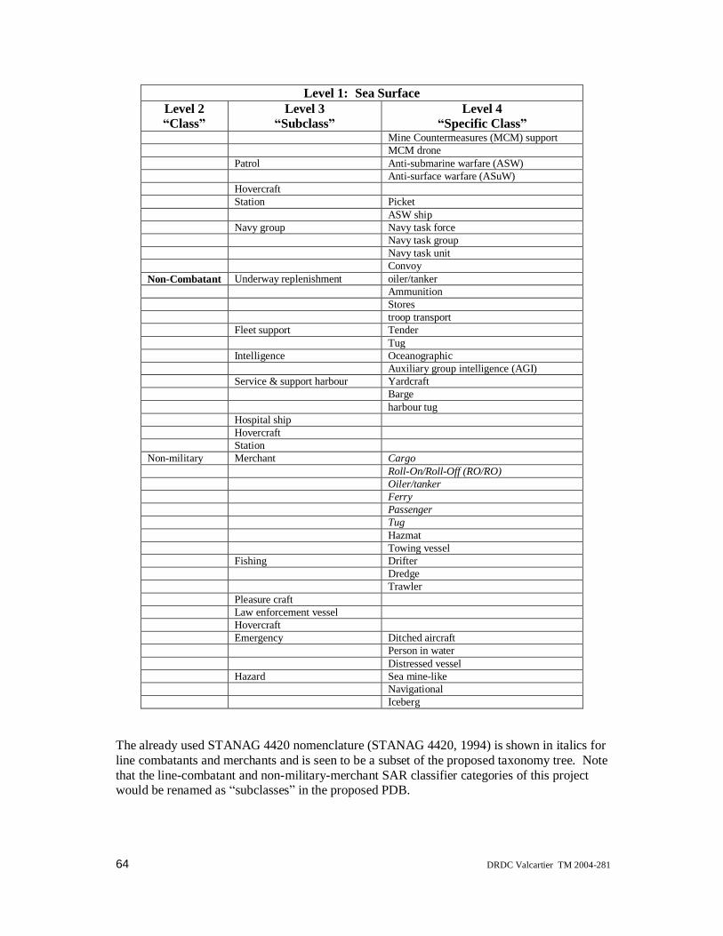
64 DRDC Valcartier TM 2004-281
Level 1: Sea SurfaceLevel 2Class
Level 3Subclass
Level 4Specific Class
Mine Countermeasures (MCM) supportMCM drone
Patrol Anti-submarine warfare (ASW)Anti-surface warfare (ASuW)
HovercraftStation Picket
ASW shipNavy group Navy task force
Navy task groupNavy task unitConvoy
Non-Combatant Underway replenishment oiler/tankerAmmunitionStorestroop transport
Fleet support TenderTug
Intelligence OceanographicAuxiliary group intelligence (AGI)
Service & support harbour YardcraftBargeharbour tug
Hospital shipHovercraftStation
Non-military Merchant CargoRoll-On/Roll-Off (RO/RO)Oiler/tankerFerryPassengerTugHazmatTowing vessel
Fishing DrifterDredgeTrawler
Pleasure craftLaw enforcement vesselHovercraftEmergency Ditched aircraft
Person in waterDistressed vessel
Hazard Sea mine-likeNavigationalIceberg
The already used STANAG 4420 nomenclature (STANAG 4420, 1994) is shown in italics forline combatants and merchants and is seen to be a subset of the proposed taxonomy tree. Notethat the line-combatant and non-military-merchant SAR classifier categories of this projectwould be renamed as subclasses in the proposed PDB.
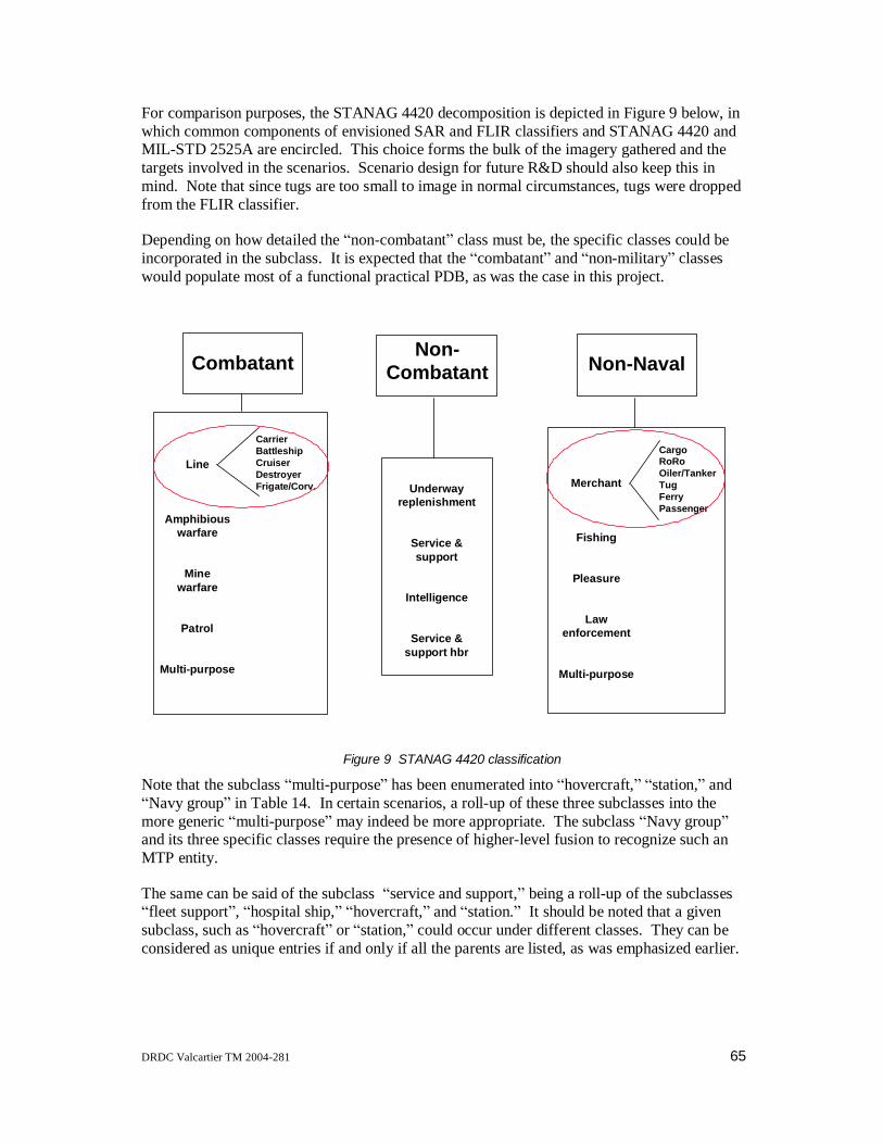
DRDC Valcartier TM 2004-281 65
For comparison purposes, the STANAG 4420 decomposition is depicted in Figure 9 below, inwhich common components of envisioned SAR and FLIR classifiers and STANAG 4420 andMIL-STD 2525A are encircled. This choice forms the bulk of the imagery gathered and thetargets involved in the scenarios. Scenario design for future R&D should also keep this inmind. Note that since tugs are too small to image in normal circumstances, tugs were droppedfrom the FLIR classifier.
Depending on how detailed the non-combatant class must be, the specific classes could beincorporated in the subclass. It is expected that the combatant and non-military classeswould populate most of a functional practical PDB, as was the case in this project.
Non-CombatantCombatant Non-Naval
Line
Amphibiouswarfare
Minewarfare
Patrol
Multi-purpose
CarrierBattleshipCruiserDestroyerFrigate/Corv. Underway
replenishment
Service &support
Intelligence
Service &support hbr
Merchant
Fishing
Pleasure
Lawenforcement
Multi-purpose
CargoRoRoOiler/TankerTugFerryPassenger
Figure 9 STANAG 4420 classification
Note that the subclass multi-purpose has been enumerated into hovercraft, station, andNavy group in Table 14. In certain scenarios, a roll-up of these three subclasses into the
more generic multi-purpose may indeed be more appropriate. The subclass Navy groupand its three specific classes require the presence of higher-level fusion to recognize such anMTP entity.
The same can be said of the subclass service and support, being a roll-up of the subclassesfleet support , hospital ship, hovercraft, and station. It should be noted that a given
subclass, such as hovercraft or station, could occur under different classes. They can beconsidered as unique entries if and only if all the parents are listed, as was emphasized earlier.

66 DRDC Valcartier TM 2004-281
Entries in the taxonomy tree that have the monikers multi- or other are often roll-ups ofseveral entries at the same level.
Finally, the class non-military corresponds to STANAG s strangely named non-naval inFigure 9 (probably non-naval means non-Navy ). A few more specific classes areproposed for merchants, and multi-purpose in this case is a roll-up of hovercraft (again),emergency and hazard . The hazard specific class iceberg would only be needed in an
MTP involving surface ships, in order to prevent accidents, and would require rathersophisticated FLIR imaging post-processing. The question of obtaining validation data forany FLIR classifier required to detect icebergs is problematic.
4.2.2 Subsurface domainFuture research should attempt to include acoustic data that could help identify the platformbefitting Table 15 below.
Table 15 Class, subclass, and specific class for the domain subsurface
Level 1: Subsurface
Level 2Class
Level 3Subclass
Level 4Specific Class
Submarine Nuclear propulsion StrategicAttackGuided missile
Conventional propulsion Conventional strategicConventional attackConventional guided missile
Other submersible RescueResearchUnderwater tug
StationUnderwater weapon Torpedo
Sea mine Sea mine (ground)Sea mine (moored)Sea mine (floating)Sea mine (other position)
Underwater decoyNon-submarine Diver Hardtop diver
Scuba diverBottom return/NOMBO Seabed installation/manmade
Seabed rock/stone, obstacle, otherWreck
Marine lifeSea anomaly (wake, knuckle, current)
Table 15 shows an example of specific classes referred to only by their parent subclass. Inthis case, sea anomaly refers to a wake, knuckle or current. This would be appropriate if therewere no sensors or no image post-processing tool in the list of imaging sensors available toform the MTP that can distinguish between the three alternatives. If a sufficiently powerfulimage processing tool can be implemented that can distinguish between a wake and a current,

DRDC Valcartier TM 2004-281 67
in a RADARSAT image for example, then the decomposition of the sea anomaly subclassinto three specific classes would be warranted. In the same vein, the distinction betweenhardtop and scuba diver would entail distinguishing cylindrical objects from spherical ones ofroughly the same small size, a feat that is hard to achieve. If this distinction is not importantfor the missions, it could be folded into its parent diver subclass.
Also of interest in Table 15 is the fact that the specific classes under the subclass sea minepresuppose that contextual information and geo-referencing can be used in the fusion processto distinguish, for example, moored from floating .
4.2.3 Air domainThe air domain is by far the most complicated and can lead to many more than five levels ofclassification in the taxonomy tree. Whether this should be avoided or utilized depends onmany factors, both operational and practical. Too much detail in the taxonomy is bound toincrease evidential reasoning processing time and can present the operator with an operatingpicture that is too detailed at the target level.
Table 16 Class, subclass, and specific class for the domain air
Level 1: Air
Level 2Class
Level 3Subclass
Level 4Specific Class
Military Fixed wing BomberFighter/interceptorTrainerAttack/strikeVertical/short take-off and landing (V/STOL)TankerCargo airliftElectronic countermeasuresMEDEVACReconnaissance (EXPANDED BY SUB-SPECIFICS)Patrol (EXPANDED BY SUB-SPECIFICS)Utility (EXPANDED BY CAPACITY)Communications (for C3I)Combat search and rescue (CSAR)Airborne command post (command and control (C2))Drone (remotely piloted vehicle (RPV)/unmanned aerial vehicle (UAV))ASW carrier-basedSpecial operations forces (SOF)
Helicopter AttackASW/maritime patrol aircraft (MPA)Utility (EXPANDED BY CAPACITY)Mine countermeasuresCSARReconnaissanceDrone (RPV/UAV)Cargo airlift/transport (EXPANDED BY CAPACITY)TrainerMEDEVAC
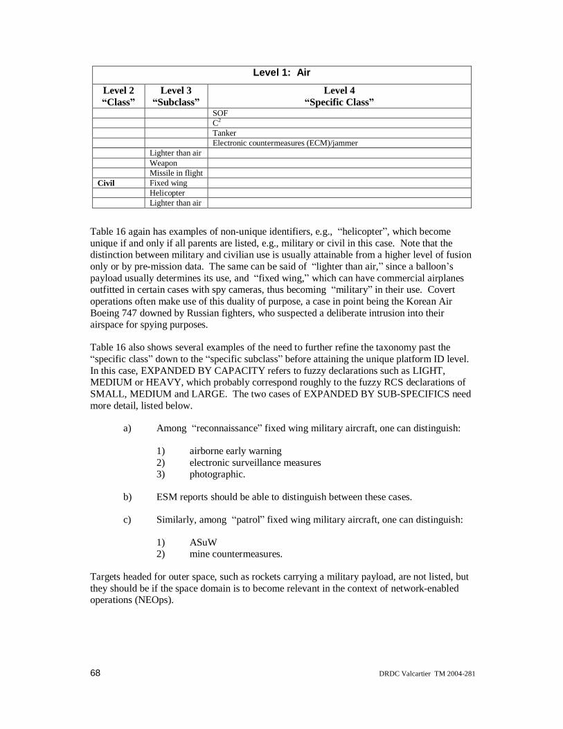
68 DRDC Valcartier TM 2004-281
Level 1: Air
Level 2Class
Level 3Subclass
Level 4Specific Class
SOFC2
TankerElectronic countermeasures (ECM)/jammer
Lighter than airWeaponMissile in flight
Civil Fixed wingHelicopterLighter than air
Table 16 again has examples of non-unique identifiers, e.g., helicopter , which becomeunique if and only if all parents are listed, e.g., military or civil in this case. Note that thedistinction between military and civilian use is usually attainable from a higher level of fusiononly or by pre-mission data. The same can be said of lighter than air, since a balloon spayload usually determines its use, and fixed wing, which can have commercial airplanesoutfitted in certain cases with spy cameras, thus becoming military in their use. Covertoperations often make use of this duality of purpose, a case in point being the Korean AirBoeing 747 downed by Russian fighters, who suspected a deliberate intrusion into theirairspace for spying purposes.
Table 16 also shows several examples of the need to further refine the taxonomy past thespecific class down to the specific subclass before attaining the unique platform ID level.
In this case, EXPANDED BY CAPACITY refers to fuzzy declarations such as LIGHT,MEDIUM or HEAVY, which probably correspond roughly to the fuzzy RCS declarations ofSMALL, MEDIUM and LARGE. The two cases of EXPANDED BY SUB-SPECIFICS needmore detail, listed below.
a) Among reconnaissance fixed wing military aircraft, one can distinguish:
1) airborne early warning2) electronic surveillance measures3) photographic.
b) ESM reports should be able to distinguish between these cases.
c) Similarly, among patrol fixed wing military aircraft, one can distinguish:
1) ASuW2) mine countermeasures.
Targets headed for outer space, such as rockets carrying a military payload, are not listed, butthey should be if the space domain is to become relevant in the context of network-enabledoperations (NEOps).

DRDC Valcartier TM 2004-281 69
4.2.4 Ground or land domainThis domain will become more important when littoral scenarios are considered, or whenRADARSAT imagery is used. It was not needed for the four scenarios of this project, sinceonly maritime surveillance was considered. It is listed here in anticipation of building a largerMTP. The Canadian MHP, now dubbed the Cyclone CH-92 (made by Sikorsky) may becalled into play to provide close-in sensor data of land targets in somewhat the same way thatLAMPS (also made by Sikorsky, and recently re-named as MH-60R Seahawk) is used in theUSA.
Table 17 Class, subclass, and specific class for the domain ground or land
Level 1: Ground (Or Land)Level 2Class
Level 3Subclass
Level 4Specific Class
Groundvehicle
Armoured Tank (EXPANDED BY SIZE)
Armoured personnel carrierArmoured infantryC2V/armoured combat vehicle (ACV)Combat service support vehicleLight armoured vehicle
Engineer vehicle BridgeEarthmoverConstruction vehicleMine laying vehicle (EXPANDED BY SUB-SPECIFICS)Dozer
Train locomotiveCivilian vehicle
Weapons Missile launchersSingle rocket launcherMultiple rocket launcherAntitank rocket launcherOther
Sensor RadarEmplaced
Special LaserNBC equipmentFlame throwerLand mines
Installation Materiel facilityShip constructionGovernment leadershipAirportOther
The potentiality of further taxonomy levels beyond the ones listed here exists in the landdomain, particularly for tanks by size (roughly corresponding to different RCS magnitudes),for other weapons by sub-specifics (such as direct fire gun, howitzer), and for mine layingvehicles by sub-specifics (armoured vehicle mounted, trailer mounted, armoured carrier withVolcano, truck mounted with Volcano).
70 DRDC Valcartier TM 2004-281
5. ConclusionThe current suite of sensors on Canada s CP-140s, as well as those to be upgraded under theAurora Incremental Modernization Program (AIMP), require solutions for automated missionmanagement systems for the next millennium. The sensor suite for a typical airbornemaritime surveillance aircraft, such as the CP-140, includes a synthetic aperture radar (SAR),a forward looking infra-red (FLIR) imaging sensor, as well as non-imaging sensors such asradar, interrogation friend or foe (IFF), electronic support measures (ESM), and datalinkinformation. As currently defined, AIMP will perform the SAR upgrade, provide a newEO/IR system to replace the FLIR, and fit a much improved ESM.
The varied data coming from such a multitude of sensors require multi-sensor data fusion(MSDF) techniques to avoid operator overload and provide a global tactical picture withincreased efficiency. This report has therefore focused on the generation of such situationawareness through the Level 1 (MSDF) data fusion process.
Amongst the scenarios and missions that need to be addressed, four main missions have beenselected and described in detail, with the first two employing all the sensors that are likely tobe fused:
• Maritime Air Area Operations (MAAO)
• Direct Fleet Support (DFS)
• Counter-Drug Operations
• Maritime Sovereignty Operations.
Given the characteristics of the sensors present and foreseen for the CP-140, a selection wasmade of those likely to have their information fused: imaging sensors such as the FLIR andSAR, and non-imaging sensors such as radar, ESM and IFF. Other sensors relevant for USCor post-mission analysis will not be considered further.
The available data fusion data/information fusion architectures, processes and algorithms havebeen described, and a hybrid architecture found to be best suited to the problem at hand.
The set of a priori databases needed for identity estimation from the attributes measured bythe sensors has been described for a baseline demonstration, which will be performed in thenext documents (particularly the third) and given in an appendix. A suggestion for furtherdatabases including the land domain and further refinements consistent with standards such asSTANAG 4420 and MIL-STD 2525 has also been outlined.
It should be said that a version of the database now exists for over 2,200 platforms, dividedroughly into about 1,500 surface and sub-surface vessels and about 700 airborne targets(CSES task 0014, 2002, and referenced documents therein), and any further demonstration ofinformation fusion for airborne maritime surveillance and C2 operations should preferably usethis extended database, possibly divided into the two separate components described abovefor computational efficiency.
Extensions to such databases, covering attributes relevant for fusion at Levels 2 and 3, werealso described. These extensions were also partly considered in CSES task 0014 (2002).
DRDC Valcartier TM 2004-281 71
6. References
Bar-Shalom, Y. & Fortmann, T.E. (1988). Tracking and Data Association, Academic Press,Mathematics in Science and Engineering, Vol. 179, ISBN 0-12-079760-7 (1988).
Bar-Shalom, Y. (1990). Multitarget-Multisensor Tracking: Advanced Applications, (Y. Bar-Shalom, ed.), Artech House, ISBN 0-89006-377-X, 1990.
Blackman, S.S. (1986). Multiple-Target Tracking with Radar Application, Artech House,ISBN 0-89006-179-3
Bossé, E. & Roy, J. (1996). Results of Sensor Fusion Feasibility Study for the CP-140Maritime Patrol Aircraft, DREV Report No. 4529, February 1996.
Boyd, John R. (1986). Patterns of Conflict, 8-hour briefing by Col. John. R. Boyd (USAF); onp. 132 is the first reference to the OODA loop, December 1986. A scanned copy of thismonumental 193-page manuscript can be found at http://www.d-n-i.net/boyd/pdf/poc.pdf
Canadian Marconi Company (CMC, 1993). Human Factors Engineering Study: CP-140mission scenarios extracted from Doc NO 1000-1016 and 1000-1028 (1993).
CP-140 (1990). Document C-12-140-OG1/MD-004. CP-140 Non-acoustic sensor equipmentdescription
CP-140 (1991), Document C-12-140-OG1/MD-001, CP-140/CP-140A CommunicationSystem Equipment Description, 2 volumes.
CSES Task 0014 (2002), MSDF/STARM Libraries Study - Final Report, Lockheed MartinCanada DM #6520014011 Rev. 1 (4 November 2002)
Dempster, A. (1967). Upper and Lower Probabilities Induced by Multivalued Mapping, Ann.Math. Statist., vol. 38, pp. 325 339, 1967.
Duclos-Hindié, N. et al., (1995). CASE-ATTI Sensor Module Programmer s Guide, version1.2, by Groupe INFORMISSION inc., 1995.
Gadaleta, S., Poore, Aubrey B., & Slocumb, B. (2002). Some Assignment Problems Arisingfrom Cluster Tracking, Proceedings of the Workshop on Signal Processing, Communications,Chaos and Systems, A Tribute to Rabinder N. Madan, June 20, 2002, Newport, RI, N.S.V.Rao, J. Barhen, C.W. Glover, W.D. Blair, A.S. Smith-Carroll, eds., ISBN0-9648312-6-0(2002).
Jane s Information Group (various years from 1979 to 1997):
Collection of Jane s Fighting Ships, London:
1995-96, edited by Cpt. Richard Sharpe
1993-94, edited by Cpt. Richard Sharpe
1991-92, edited by Cpt. Richard Sharpe
1989-90, edited by Cpt. Richard Sharpe
1987-88, edited by Cpt. John Moore

72 DRDC Valcartier TM 2004-281
1984-85, edited by Cpt. John Moore
1979-80, edited by Cpt. John Moore
Jane s Merchant Ships 1996-97, edited by David Greenman
Collection of Jane s All the World s Aircraft:
1996-1997, edited by Paul Johnson
1994-1995, edited by Mark Lambert
1991-1992, edited by Mark Lambert
1982-1983, edited by John W. Taylor
Collection of Jane s Avionics:
1996-97, edited by Chris Johnson
1993-94, edited by David Brinkman
1990-91, edited by David Brinkman
1989-90, edited by David Brinkman
Collection of Jane s Naval Weapon Systems:
1994-95, edited by E.R. Hooton
1985-86, edited by Ronald T. Pretty
1983-84, edited by Ronald T. Pretty
Klein, L.A. (1993). Sensor and Data Fusion Concepts and Applications, Tutorial Texts inOptical Engineering, SPIE Optical Engineering Press, Vol TT 14, 1993.
Lockheed (1979). Lockheed Annex C to detail specification, Model CP-140, LR 26662-1AC,30 March 1979.
McCandless Jr., S. W. & Mango, S.A. (1997). George Washington University Course No. 664,held in Kanata, Ontario, August 12-15, 1997.
MIL-STD-2525B (1999). Common Warfighting Symbology, 30 January 1999, supersedingMIL-STD-2525A, 15 December 1996
Pryde, G.C., Bekett, K., Delves, L., Oliver, C. & White, R. (1994). Design of a Real-TimeHigh Quality SAR Processor, Proceedings SPIE Vol. 2230, Conference on Algorithms forSynthetic Aperture Imagery, Orlando, 1994, pp. 148-159.
Roy, J.M.J., Bossé, E. & Dion, D. (1995). CASE-ATTI (Concept Analysis and SimulationEnvironment for Automatic Target Tracking and Identification): an Algorithm-Level Testbedfor Multi-Sensor Data Fusion, DREV Report No. R-9411, May 1995.
Roy, J.M.J., Duclos-Hindié, N., & Bossé, E., (1999). An Algorithm-Level Test Bed for Level-One Data Fusion Studies, Proceedings of the International Conference on Data Fusion EuroFusion99, 5-7 October 1999, Stratford-upon-Avon, UK, pp. 207-215 , 1999
Shafer, G. (1976). A Mathematical Theory of Evidence, Princeton University Press, 1976.

DRDC Valcartier TM 2004-281 73
SSAR ADM PRS (1996). SSAR ADM Performance Requirements Specification document15841-SSAR-100 (SSAR SEM) Version 4.0, 14 June 1996 (unclassified without Appendix).
Stacy, N., Burgess, M., Douglass, J., Muller, M. & Robinson, M. (1994). A real-timeprocessor for the Australian synthetic aperture radar, Proceedings IEEE ICASSP, Vol. 5,Adelaide, 1994, pp. 193-196.
STANAG 4420 (1994). NATO, Display Symbology and Colour for NATO Maritime Units,Military Agency for Standardization (MAS), NATO, June 1994.
Steinberg, A.N., Bowman, C.L., & White, F.E. (1999). Revisions to the JDL Data FusionModel , in Sensor Fusion: Architectures, Algorithms, and Applications, SPIE Proceedings,Vol. 3719, 1999
Unisys (1993). Investigations of Attribute Information Fusion Techniques for Target IdentityEstimation (AIFIE). 2 volumes, DM 112000025, 6 October 1993.
Valin, P., Bossé, E., (2003). Using a priori databases for identity estimation throughevidential reasoning in realistic scenarios, RTO IST Symposium on Military Data andInformation Fusion , Prague, Czech Republic, 20-22 October 2003.
Waltz, E. & Llinas, J. (1990). Multisensor Data Fusion, Artech House, ISBN 0-89006-277-3,1990.

74 DRDC Valcartier TM 2004-281
7. Acronyms
The list of acronyms presented here serves for all three documents TM-281, TR-282 and TR-283.
AAM Air-to-Air MissileADM Advanced Development ModelAIFIE Attribute Information Fusion techniques for target Identity EstimationAIMP Aurora Incremental Modernization ProjectAIR Average ID RateAOP Area Of ProbabilityAR Auto-RegressiveASCACT Advanced Shipborne Command and Control TechnologyASM Air-to-Surface MissileAWACS Airborne Warning And Control SystemBB BlackBoardBPA Basic Probability AssignmentBPAM Bayesian Percent Attribute MissC2 Command and ControlC4I Command, Control, Communications, Computer and IntelligenceCAD Computer-Aided DesignCANEWS Canadian Electronic Warfare SystemCASE-ATTI Concept Analysis and Simulation Environment for Automatic Target
Tracking and IdentificationCCIS Command and Control Information SystemCCS Command and Control SystemCDO Counter-Drug OperationsCF Canadian ForcesCIO Communications Intercept OperatorCIWS Close-In Weapon SystemCL Confidence LevelCM Centre of MassCOMDAT Command Decision Aid TechnologyCOMINT Communications IntelligenceCOTS Commercial Off-The-ShelfCPF Canadian Patrol FrigateCPU Central Processing UnitCRAD Chief of Research And DevelopmentCSES Combat System Engineering ServicesCSIS Combat Support In-ServiceDAAS Decision Aids for Airborne SurveillanceDF Data FusionDFCP Data Fusion between Collaborating PlatformsDFDM Data Fusion Demonstration Model

DRDC Valcartier TM 2004-281 75
DFS Direct Fleet SupportDM Data MileDMS Data Management SystemDPG Defence Planning GuidanceDRDC-O Defence R&D Canada OttawaDRDC-V Defence R&D Canada ValcartierDS Dempster-ShaferDSC Digital Scan ConverterEDM Engineering Development ModelEGI Embedded GPS and INSELINT Electronic IntelligenceELNOT ELINT NotationEMCON Emission ControlENL Emitter Name ListEO Electro-OpticESM Electronic Support MeasuresFLIR Forward Looking Infra-RedFM Frequency ModulationGIS Geographical Information SystemGPAF General Purpose Air ForcesGPDC General Purpose Digital ComputerGPL Geo-Political ListingGPS Global Positioning SystemHCI Human Computer InterfaceHLA High Level ArchitectureHW HardWareID IdentificationIFF Identification Friend or FoeIMM Interacting Multiple ModelINS Inertial Navigation SystemIR Infra-RedIRST Infra-Red Search and TrackISAR Inverse SARISIF International Society of Information FusionISM Image Support ModuleISTDS Internal System Track Data StoreJAIF Journal of Advances in Information FusionJDL Joint Directors of LaboratoriesJPDA Joint Probabilistic Data AssociationJVC Jonker-Volgenant-CastanonKBS Knowledge-Based SystemLAMPS Light Airborne Multi-Purpose SystemLAP Local Area PictureLM Lockheed MartinMAAO Maritime Air Area OperationsMAD Magnetic Anomaly Detector

76 DRDC Valcartier TM 2004-281
MALO Maritime Air Littoral OperationsMARCOT Maritime Coordinated Operational TrainingMFA Multi-Frame AssociationMHP Maritime Helicopter ProjectMHT Multiple Hypothesis TrackingMIL-STD Military Standard (US)MOP Measure Of PerformanceMSDF Multi-Source Data FusionMSP Maritime Sovereignty PatrolMTP Maritime Tactical PictureNASO Non-Acoustic Sensor OperatorNATO North Atlantic Treaty OrganizationNAVCOM Navigation CommunicationNAWC Naval Air Warfare CenterNCW Network Centric WarfareNEOps Network-Enabled OperationsNILE NATO Improved Link ElevenNM Nautical MileNN Neural NetworkOMI Operator-Machine InterfaceOODA Observe, Orient, Decide, ActOR Object RecognitionOTHT Over-The-Horizon TargetingPDA Probabilistic Data AssociationPDB Platform Data BasePU Participating UnitPWGSC Public Works and Government Services CanadaR&D Research and DevelopmentRATT Radio TeleTypeRCMP Royal Canadian Mounted PoliceRCS Radar Cross-SectionRDP Range Doppler ProfilerRM Resource ManagementRMP Recognized Maritime PictureROI Region Of InterestRPM Revolutions Per MinuteSAM Surface-to-Air MissileSAR Synthetic Aperture RadarSARP SAR ProcessorSC Ship CategorySDC-S Signal Data Converter-StorerSHINPADS Shipboard Integrated Processing And Display SystemSKAD Survival Kit Air DroppableSL Ship LengthSNNS Stuttgart Neural Net SimulatorSNR Signal-to-Noise Ratio

DRDC Valcartier TM 2004-281 77
SS Sea StateSSAR Spotlight SARSSC Surface Surveillance and ControlSSM Surface-to-Surface MissileST Ship TypeSTA Situation and Threat AssessmentSTANAG Standardization NATO AgreementSTIM StimulationSW SoftwareTACNAV Tactical NavigationTD Technology DemonstratorTDS Truncated DSTM Track ManagementUN United NationsUSC Underwater Surveillance and ControlVOI Volume Of InterestWAP Wide Area PictureXDM eXperimental Development Model

78 DRDC Valcartier TM 2004-281
8. Annexes
8.1 Main sources of documentation
8.1.1 General data/information fusion sourcesSince information/data fusion is an emerging science that incorporates elements of physics,engineering, mathematical physics and computational science, the International Society ofInformation Fusion (ISIF) was created in 1999, with a constitution approved in April 2000.
For ISIF, information fusion encompasses the theory, techniques and tools conceived andemployed for exploiting the synergy in the information acquired from multiple sources(sensors, databases, information gathered by humans, etc.), such that the resulting decision oraction is in some sense better (qualitatively or quantitatively, in terms of accuracy, robustness,etc.) than would be possible if any of these sources were used individually without suchsynergy exploitation. In doing so, events, activities and movements will be correlated andanalyzed as they occur in time and space, to determine the location, identity and status ofindividual objects (equipment and units), to assess the situation, to qualitatively andquantitatively determine threats, and to detect patterns in activity that reveal intent orcapability. Specific technologies are required to refine, direct and manage information fusioncapabilities.
The ISIF web site at http://www.inforfusion.org contains much of the crucial documentationin the whole domain. The results contained in this series of reports were presented in part atthe first seven ISIF-sponsored FUSION conferences in
2004: Stockholm, Sweden, at http://www.fusion2004.org/
2003: Cairns, Queensland, Australia at http://fusion2003.ee.mu.oz.au/
2002: Annapolis, Maryland, USA athttp://www.inforfusion.org/Fusion_2002_Website/index.htm
2001: Montreal, Quebec, Canada at http://omega.crm.umontreal.ca/fusion/, with bothLockheed Martin Canada and DRDC-V as sponsors
2000: Paris, France, at http://www.onera.fr/fusion2000/
1999: Sunnyvale, California, USA, at http://www.inforfusion.org/fusion99/, duringwhich the concept of ISIF first emerged
1998: Las Vegas, Nevada, USA, at http://www.inforfusion.org/fusion98/
The eighth such conference was held in Philadelphia, Pennsylvania, USA, on July 25-28,2005 (see http://www.fusion2005.org/ for more details).
In addition, summaries were presented internationally for NATO through their ResearchTechnology Agency (RTA) symposia and their Advanced Study Institutes (ASI). Othervenues where this research work was promulgated include the SPIE Aerosense series held inOrlando each year, and various other conferences. The SPIE Aerosense series has recentlybeen renamed SPIE Defense & Security Symposium.
DRDC Valcartier TM 2004-281 79
The ISIF community is also served by the Information Fusion Journal published by Elsevier(see http://www.elsevier.com/wps/find/journaldescription.cws_home/620862/description formore information), and has an on-line journal of its own, the Journal of Advances inInformation Fusion (JAIF), with information on submissions athttp://www.inforfusion.org/JAIF-CFP-Oct28.htm.
As for the documentation specifically needed for this report, the section entitled Referencescontains the complete list.
8.1.2 Specific related data/information fusion sourcesThe contents of this series of three reports is based on two contracts entitled
1. Demonstrations of Data Fusion Concepts for Airborne Surveillance, and
2. Demonstrations of Image Analysis and Object Recognition Decision Aids forAirborne Surveillance,
with the following 14 deliverables (the date of the first publication of each report is shown,and the date of the final revision, where applicable):
1. LM Canada Doc. No. 990001006, (1997a). MSDF Requirements SpecificationDocument for Year 1 of PWGSC Contract No. W7701-6-4081 on Real-Time Issuesand Demonstrations of Data Fusion Concepts for Airborne Surveillance (andreferences therein), final Rev.1 dated 27 September 1999.
2. LM Canada Doc. No. 990001007, (1997b). MSDF Design Document for Year 1 ofPWGSC Contract No. W7701-6-4081 on Real-Time Issues and Demonstrations ofData Fusion Concepts for Airborne Surveillance (and references therein), final Rev.1dated 27 September 1999.
3. LM Canada Doc. No. 990001008, (1998a). MSDF Implementation and TestDocument for Year 1 of PWGSC Contract No. W7701-6-4081 on Real-Time Issuesand Demonstrations of Data Fusion Concepts for Airborne Surveillance (andreferences therein), final Rev.1 dated 27 September 1999.
4. LM Canada Doc. No. 990001009, (1998b). MSDF Requirements SpecificationDocument for Year 2 of PWGSC Contract No. W7701-6-4081 on Real-Time Issuesand Demonstrations of Data Fusion Concepts for Airborne Surveillance (andreferences therein), final Rev.1 dated 27 September 1999.
5. LM Canada Doc. No. 990001010, (1998c). MSDF Design Document for Year 2 ofPWGSC Contract No. W7701-6-4081 on Real-Time Issues and Demonstrations ofData Fusion Concepts for Airborne Surveillance (and references therein), final Rev.1dated 27 September 1999.
6. LM Canada Doc. No. 990001011, (1999). MSDF Implementation and Test Documentfor Year 2 of PWGSC Contract No. W7701-6-4081 on Real-Time Issues andDemonstrations of Data Fusion Concepts for Airborne Surveillance (and referencestherein), final Rev.1 dated 27 September 1999.
7. LM Canada Doc. No. 990001012, (2000a). MSDF Requirements SpecificationDocument for Year 3 of Contract No. W7701-6-4081 on Real-Time Issues andDemonstrations of Data Fusion Concepts for Airborne Surveillance (and referencestherein), Rev. 0, 23 February 2000.
80 DRDC Valcartier TM 2004-281
8. LM Canada Doc. No. 990001013, (2000b). MSDF Design Document for Year 3 ofPWGSC Contract No. W7701-6-4081 on Real-Time Issues and Demonstrations ofData Fusion Concepts for Airborne Surveillance (and references therein), Rev. 0, 23February 2000.
9. LM Canada Doc. No. 990001014, (2000c). MSDF Implementation and TestDocument for Year 3 of PWGSC Contract No. W7701-6-4081 on Real-Time Issuesand Demonstrations of Data Fusion Concepts for Airborne Surveillance (andreferences therein), Rev. 1, 20 March 2000.
10. LM Canada DM No. 990001234-a, (2001a). Detailed Design Document - Part 1,Demonstrations of Image Analysis and Object Recognition Decision Aids forAirborne Surveillance, Contract No. W2207-8-EC01, Rev. 0, 22 January 2001.
11. LM Canada DM No. 990001234-b, (2001b). Detailed Design Document - Part 2,Demonstrations of Image Analysis and Object Recognition Decision Aids forAirborne Surveillance, Contract No. W2207-8-EC01, Rev. 0, 22 January 2001.
12. LM Canada DM No. 990001235-a, (2001c). Testing and Benchmarking IMM-CVCAvs Kalman Filtering, Demonstrations of Image Analysis and Object RecognitionDecision Aids for Airborne Surveillance, Contract No. W2207-8-EC01, Rev. 0, 22January 2001.
13. LM Canada DM No. 990001235-b, (2001d). Testing and Benchmarking ShipClassifier for SAR Imagery, Demonstrations of Image Analysis and ObjectRecognition Decision Aids for Airborne Surveillance, Contract No. W2207-8-EC01,Rev. 0, 22 January 2001.
14. LM Canada DM No. 990001236, (2001e). Final Report, Demonstrations of ImageAnalysis and Object Recognition Decision Aids for Airborne Surveillance. ContractNo. W2207-8-EC01, Rev. 0, 22 January 2001.

DRDC Valcartier TM 2004-281 81
8.2 Platform DataBase (PDB)The entries in the PDB that will be used in this sequence of reports are shown in the followingformat: the first half of the fields are displayed for all platforms on three pages, followed bythe remaining fields for the same platforms on the next three pages, in such a way that theycan be put end-to-end. All the information in the PDB and the ENL (in the next section)comes from the compilation of books by Jane s Information Group (various years from 1979to 1997, as shown in the references section):
Several remarks are in order at this time for a proper interpretation of the entries:
a. Many platforms are enumerated in different variants, which differ mostly byone or two emitters in their emitter list, corresponding to sequential platformupgrades. Still, some platform ship entries share all of their attributes but arestill listed as independent entries, because their name (or equivalently theirhull numbers) could be visible through EO sensors or could be obtainedthrough a priori knowledge of their point of departure (from commercial shipregistries such as Lloyd s or military information).
b. Some attribute fields are left blank either because no reliable informationcould be found at this time, or because the information is intentionally left outto ensure that this report remains unclassified (particularly after entry 127).
c. In some cases, the emitter list may be so specific that it indicates some uniqueship rather than a variant of a specific class.
It should be noted that a separate CSES task has enlarged this PDB to more than 2200 entriesby using military databases from registered accounts to Periscope, the home of the US NavalInstitute Military Database available through http://www.periscopeone.com/. With the adventof Jane s on-line subscription services at http://www.janes.com , this PDB should be updatedat regular intervals, rather than perusing the print publications of Jane s Information Group, aswas done prior to 1997 (see the references section).
Finally, the GPL entries used in the scenarios are straightforward, with enemy ships explicitlyidentified as such in the scenarios. Allegiance is of secondary importance for these reports,even though it can be easily determined.

82 DRDC Valcartier TM 2004-281
ID # NAME---------------- PLATYPE SUBTYPE OFFENS CONT V_MINI
V_MAXI
ACC ALT_MAXIM
LEN HEI WID
000001 JAHRE-VICKING------- SURFCOM TANKERV HARMLE DENM 0 35 999 0 460 33 51000002 HALIFAX-CPF--------- SURMILI FRIGATE MEDIOF CANA 0 35 999 0 130 5 16000003 TARIQ-AMAZON-------- SURMILI FRIGATE WEAKOF PAKI 0 30 999 0 110 4 13000004 BELKNAP------------- SURMILI CRUISER STROOF USAM 0 38 999 0 167 9 17000005 BREMEN-------------- SURMILI FRIGATE STROOF GERM 0 30 999 0 130 7 15000006 BROADSWORD-BATCH-1-- SURMILI FRIGATE STROOF BRIT 0 30 999 0 131 6 15000007 CALIFORNIA---------- SURMILI CRUISER STROOF USAM 0 35 999 0 182 10 19000008 COONTZ-------------- SURMILI DESTROY STROOF USAM 0 35 999 0 156 5 16000009 IMPROVED-RESTIGOUCHE SURMILI FRIGATE MEDIOF CANA 0 28 999 0 113 4 13000010 MACKENZIE----------- SURMILI FRIGATE WEAKOF CANA 0 28 999 0 112 4 12000011 GRISHA-III(ALBATROS) SURMILI FRIGATE WEAKOF LITH 0 30 999 0 71 4 10000012 INVINCIBLE---------- SURMILI CARRIER MEDIOF BRIT 0 28 999 0 209 8 36000013 ST-LAURENT---------- SURMILI FRIGATE VEWEOF CANA 0 27 999 0 112 5 13000014 STE-CROIX----------- SURMILI FRIGATE VEWEOF CANA 0 25 999 0 111 4 13000015 INVINCIBLE-ILLUSTRIO SURMILI CARRIER MEDIOF BRIT 0 28 999 0 209 8 36000016 INVINCIBLE-ARK-ROYAL SURMILI CARRIER MEDIOF BRIT 0 28 999 0 209 8 36000017 VIRGINIA------------ SURMILI CRUISER STROOF USAM 0 35 999 0 178 10 19000018 MIRKA-I------------- SURMILI FRIGATE WEAKOF RUSS 0 32 999 0 82 3 9000019 MIRKA-II------------ SURMILI FRIGATE WEAKOF RUSS 0 32 999 0 82 3 9000020 KRIVAK-IA----------- SURMILI FRIGATE STROOF RUSS 0 32 999 0 124 5 14000021 KRIVAK-IB----------- SURMILI FRIGATE STROOF RUSS 0 32 999 0 124 5 14000022 KRIVAK-II----------- SURMILI FRIGATE STROOF RUSS 0 32 999 0 124 5 14000023 KRIVAK-IIIA--------- SURMILI FRIGATE STROOF RUSS 0 32 999 0 124 5 14000024 KRIVAK-IIIB--------- SURMILI FRIGATE STROOF RUSS 0 32 999 0 124 5 14000025 IROQUOIS------------ SURMILI DESTROY WEAKOF CANA 0 30 999 0 130 5 15000026 ADELAIDE------------ SURMILI FRIGATE MEDIOF AUST 0 30 999 0 138 5 14000027 IMPROVED-PROVIDER--- SURMILI SUPPORT VEWEOF CANA 0 21 999 0 172 9 23000028 QUEST--------------- SURMILI MISCELL HARMLE CANA 0 11 999 0 72 5 13000029 KNOX---------------- SURMILI FRIGATE MEDIOF EGYP 0 27 999 0 134 5 14000030 IVAN-ROGOV---------- SURMILI ASSAMPH WEAKOF RUSS 0 25 999 0 158 8 25000031 KARA-KERCH---------- SURMILI CRUISER STROOF RUSS 0 35 999 0 173 7 19000032 MODIFIED-KIEV------- SURMILI CARRIER STROOF RUSS 0 32 999 0 274 10 51000033 KIROV-ADM-USHAKOV--- SURMILI CRUISER VESTOF RUSS 0 35 999 0 252 9 29000034 SAM-KOTLIN---------- SURMILI DESTROY MEDIOF RUSS 0 36 999 0 127 5 13000035 MOSKVA-------------- SURMILI BATTLES WEAKOF RUSS 0 31 999 0 191 9 34000036 KRESTA-I------------ SURMILI CRUISER MEDIOF RUSS 0 35 999 0 156 6 17000037 TICONDEROGA--------- SURMILI CRUISER STROOF USAM 0 35 999 0 173 10 17000038 TARAWA-------------- SURMILI ASSAMPH WEAKOF USAM 0 24 999 0 254 8 40000039 SPRUANCE------------ SURMILI DESTROY STROOF USAM 0 33 999 0 172 6 17000040 NIMITZ-------------- SURMILI CARRIER WEAKOF USAM 0 35 999 0 333 11 41000041 SACRAMENTO---------- SURMILI SUPPORT WEAKOF USAM 0 26 999 0 242 12 33000042 KIROV-ADM-NAKHIMOV-- SURMILI BATTLES VESTOF RUSS 0 35 999 0 252 9 29000043 KIROV-ADM-LAZAREV--- SURMILI BATTLES VESTOF RUSS 0 35 999 0 252 9 29000044 KIROV-PYOTR-VELIKIY- SURMILI BATTLES VESTOF RUSS 0 35 999 0 252 9 29000045 KARA-AZOV----------- SURMILI CRUISER STROOF RUSS 0 35 999 0 173 7 19000046 KARA-PETROPAVLOVSK-- SURMILI CRUISER STROOF RUSS 0 35 999 0 173 7 19000047 KARA-VLADIVOSTOK---- SURMILI CRUISER STROOF RUSS 0 35 999 0 173 7 19000048 IVAN-ROGOV-ALEKSANDR SURMILI ASSAMPH WEAKOF RUSS 0 25 999 0 158 8 25000049 IVAN-ROGOV-MITROFAN- SURMILI ASSAMPH WEAKOF RUSS 0 25 999 0 158 8 25000050 CAMDEN-SACRAMENTO--- SURMILI SUPPORT WEAKOF USAM 0 26 999 0 242 12 33000051 SEATTLE-SACRAMENTO-- SURMILI SUPPORT WEAKOF USAM 0 26 999 0 242 12 33000052 DETROIT-SACRAMENTO-- SURMILI SUPPORT WEAKOF USAM 0 26 999 0 242 12 33000053 NIMITZ-DWIGHT-EISENH SURMILI CARRIER WEAKOF USAM 0 35 999 0 333 11 41000054 NIMITZ-CARL-VINSON-- SURMILI CARRIER WEAKOF USAM 0 35 999 0 333 11 41000055 NIMITZ-THEODORE-ROOS SURMILI CARRIER WEAKOF USAM 0 35 999 0 333 12 41000056 NIMITZ-ABRAHAM-LINCO SURMILI CARRIER WEAKOF USAM 0 35 999 0 333 12 41000057 NIMITZ-GEORGE-WASHIN SURMILI CARRIER WEAKOF USAM 0 35 999 0 333 12 41000058 NIMITZ-JOHN-C-STENNI SURMILI CARRIER WEAKOF USAM 0 35 999 0 333 12 41000059 NIMITZ-HARRY-S-TRUMA SURMILI CARRIER WEAKOF USAM 0 35 999 0 333 12 41000060 SPRUANCE-HAYLER----- SURMILI DESTROY STROOF USAM 0 33 999 0 172 6 17
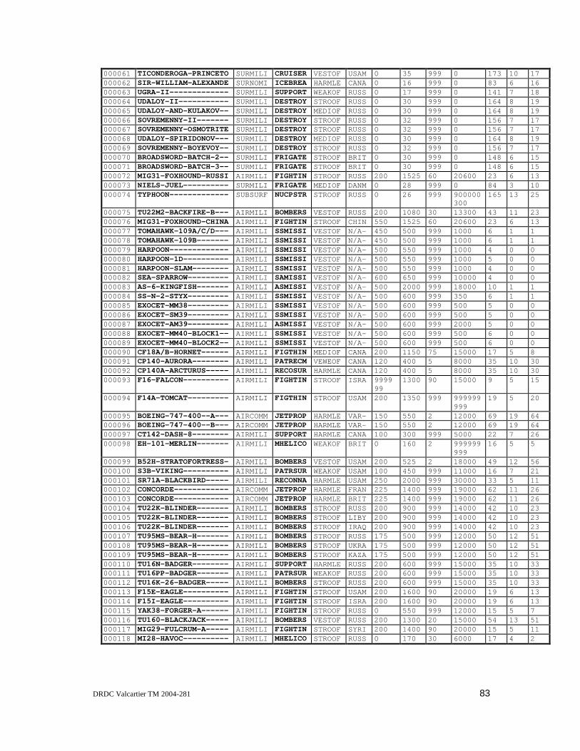
DRDC Valcartier TM 2004-281 83
000061 TICONDEROGA-PRINCETO SURMILI CRUISER VESTOF USAM 0 35 999 0 173 10 17000062 SIR-WILLIAM-ALEXANDE SURNOMI ICEBREA HARMLE CANA 0 16 999 0 83 6 16000063 UGRA-II------------- SURMILI SUPPORT WEAKOF RUSS 0 17 999 0 141 7 18000064 UDALOY-II----------- SURMILI DESTROY STROOF RUSS 0 30 999 0 164 8 19000065 UDALOY-AND-KULAKOV-- SURMILI DESTROY MEDIOF RUSS 0 30 999 0 164 8 19000066 SOVREMENNY-II------- SURMILI DESTROY STROOF RUSS 0 32 999 0 156 7 17000067 SOVREMENNY-OSMOTRITE SURMILI DESTROY STROOF RUSS 0 32 999 0 156 7 17000068 UDALOY-SPIRIDONOV--- SURMILI DESTROY MEDIOF RUSS 0 30 999 0 164 8 19000069 SOVREMENNY-BOYEVOY-- SURMILI DESTROY STROOF RUSS 0 32 999 0 156 7 17000070 BROADSWORD-BATCH-2-- SURMILI FRIGATE STROOF BRIT 0 30 999 0 148 6 15000071 BROADSWORD-BATCH-3-- SURMILI FRIGATE STROOF BRIT 0 30 999 0 148 6 15000072 MIG31-FOXHOUND-RUSSI AIRMILI FIGHTIN STROOF RUSS 200 1525 60 20600 23 6 13000073 NIELS-JUEL---------- SURMILI FRIGATE MEDIOF DANM 0 28 999 0 84 3 10000074 TYPHOON------------- SUBSURF NUCPSTR STROOF RUSS 0 26 999 900000
300165 13 25
000075 TU22M2-BACKFIRE-B--- AIRMILI BOMBERS VESTOF RUSS 200 1080 30 13300 43 11 23000076 MIG31-FOXHOUND-CHINA AIRMILI FIGHTIN STROOF CHIN 550 1525 60 20600 23 6 13000077 TOMAHAWK-109A/C/D--- AIRMILI SSMISSI VESTOF N/A- 450 500 999 1000 6 1 1000078 TOMAHAWK-109B------- AIRMILI SSMISSI VESTOF N/A- 450 500 999 1000 6 1 1000079 HARPOON------------- AIRMILI SSMISSI VESTOF N/A- 500 550 999 1000 4 0 0000080 HARPOON-1D---------- AIRMILI SSMISSI VESTOF N/A- 500 550 999 1000 5 0 0000081 HARPOON-SLAM-------- AIRMILI SSMISSI VESTOF N/A- 500 550 999 1000 4 0 0000082 SEA-SPARROW--------- AIRMILI SAMISSI VESTOF N/A- 600 650 999 10000 4 0 0000083 AS-6-KINGFISH------- AIRMILI ASMISSI VESTOF N/A- 500 2000 999 18000 10 1 1000084 SS-N-2-STYX--------- AIRMILI SSMISSI VESTOF N/A- 500 600 999 350 6 1 1000085 EXOCET-MM38--------- AIRMILI SSMISSI VESTOF N/A- 500 600 999 500 5 0 0000086 EXOCET-SM39--------- AIRMILI SSMISSI VESTOF N/A- 500 600 999 500 5 0 0000087 EXOCET-AM39--------- AIRMILI ASMISSI VESTOF N/A- 500 600 999 2000 5 0 0000088 EXOCET-MM40-BLOCK1-- AIRMILI SSMISSI VESTOF N/A- 500 600 999 500 6 0 0000089 EXOCET-MM40-BLOCK2-- AIRMILI SSMISSI VESTOF N/A- 500 600 999 500 6 0 0000090 CF18A/B-HORNET------ AIRMILI FIGTHIN MEDIOF CANA 200 1150 75 15000 17 5 8000091 CP140-AURORA-------- AIRMILI PATRECM VEWEOF CANA 120 400 5 8000 35 10 30000092 CP140A-ARCTURUS----- AIRMILI RECOSUR HARMLE CANA 120 400 5 8000 35 10 30000093 F16-FALCON---------- AIRMILI FIGHTIN STROOF ISRA 9999
991300 90 15000 9 5 15
000094 F14A-TOMCAT--------- AIRMILI FIGTHIN STROOF USAM 200 1350 999 999999999
19 5 20
000095 BOEING-747-400--A--- AIRCOMM JETPROP HARMLE VAR- 150 550 2 12000 69 19 64000096 BOEING-747-400--B--- AIRCOMM JETPROP HARMLE VAR- 150 550 2 12000 69 19 64000097 CT142-DASH-8-------- AIRMILI SUPPORT HARMLE CANA 100 300 999 5000 22 7 26000098 EH-101-MERLIN------- AIRMILI MHELICO WEAKOF BRIT 0 160 2 999999
99916 5 5
000099 B52H-STRATOFORTRESS- AIRMILI BOMBERS VESTOF USAM 200 525 2 18000 49 12 56000100 S3B-VIKING---------- AIRMILI PATRSUR WEAKOF USAM 100 450 999 11000 16 7 21000101 SR71A-BLACKBIRD----- AIRMILI RECONNA HARMLE USAM 250 2000 999 30000 33 5 11000102 CONCORDE------------ AIRCOMM JETPROP HARMLE FRAN 225 1400 999 19000 62 11 26000103 CONCORDE------------ AIRCOMM JETPROP HARMLE BRIT 225 1400 999 19000 62 11 26000104 TU22K-BLINDER------- AIRMILI BOMBERS STROOF RUSS 200 900 999 14000 42 10 23000105 TU22K-BLINDER------- AIRMILI BOMBERS STROOF LIBY 200 900 999 14000 42 10 23000106 TU22K-BLINDER------- AIRMILI BOMBERS STROOF IRAQ 200 900 999 14000 42 10 23000107 TU95MS-BEAR-H------- AIRMILI BOMBERS STROOF RUSS 175 500 999 12000 50 12 51000108 TU95MS-BEAR-H------- AIRMILI BOMBERS STROOF UKRA 175 500 999 12000 50 12 51000109 TU95MS-BEAR-H------- AIRMILI BOMBERS STROOF KAZA 175 500 999 12000 50 12 51000110 TU16N-BADGER-------- AIRMILI SUPPORT HARMLE RUSS 200 600 999 15000 35 10 33000111 TU16PP-BADGER------- AIRMILI PATRSUR WEAKOF RUSS 200 600 999 15000 35 10 33000112 TU16K-26-BADGER----- AIRMILI BOMBERS STROOF RUSS 200 600 999 15000 35 10 33000113 F15E-EAGLE---------- AIRMILI FIGHTIN STROOF USAM 200 1600 90 20000 19 6 13000114 F15I-EAGLE---------- AIRMILI FIGHTIN STROOF ISRA 200 1600 90 20000 19 6 13000115 YAK38-FORGER-A------ AIRMILI FIGHTIN STROOF RUSS 0 550 999 12000 15 5 7000116 TU160-BLACKJACK----- AIRMILI BOMBERS VESTOF RUSS 200 1300 20 15000 54 13 51000117 MIG29-FULCRUM-A----- AIRMILI FIGHTIN STROOF SYRI 200 1400 90 20000 15 5 11000118 MI28-HAVOC---------- AIRMILI MHELICO STROOF RUSS 0 170 30 6000 17 4 2
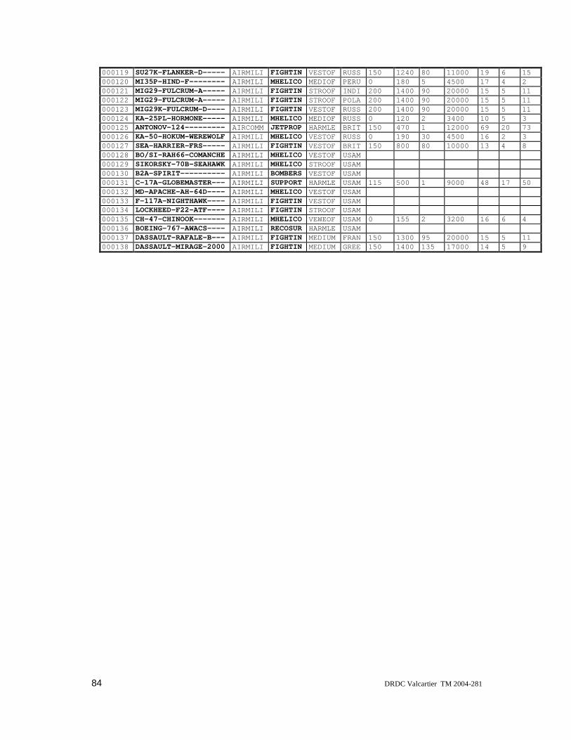
84 DRDC Valcartier TM 2004-281
000119 SU27K-FLANKER-D----- AIRMILI FIGHTIN VESTOF RUSS 150 1240 80 11000 19 6 15000120 MI35P-HIND-F-------- AIRMILI MHELICO MEDIOF PERU 0 180 5 4500 17 4 2000121 MIG29-FULCRUM-A----- AIRMILI FIGHTIN STROOF INDI 200 1400 90 20000 15 5 11000122 MIG29-FULCRUM-A----- AIRMILI FIGHTIN STROOF POLA 200 1400 90 20000 15 5 11000123 MIG29K-FULCRUM-D---- AIRMILI FIGHTIN VESTOF RUSS 200 1400 90 20000 15 5 11000124 KA-25PL-HORMONE----- AIRMILI MHELICO MEDIOF RUSS 0 120 2 3400 10 5 3000125 ANTONOV-124--------- AIRCOMM JETPROP HARMLE BRIT 150 470 1 12000 69 20 73000126 KA-50-HOKUM-WEREWOLF AIRMILI MHELICO VESTOF RUSS 0 190 30 4500 16 2 3000127 SEA-HARRIER-FRS----- AIRMILI FIGHTIN VESTOF BRIT 150 800 80 10000 13 4 8000128 BO/SI-RAH66-COMANCHE AIRMILI MHELICO VESTOF USAM000129 SIKORSKY-70B-SEAHAWK AIRMILI MHELICO STROOF USAM000130 B2A-SPIRIT---------- AIRMILI BOMBERS VESTOF USAM000131 C-17A-GLOBEMASTER--- AIRMILI SUPPORT HARMLE USAM 115 500 1 9000 48 17 50000132 MD-APACHE-AH-64D---- AIRMILI MHELICO VESTOF USAM000133 F-117A-NIGHTHAWK---- AIRMILI FIGHTIN VESTOF USAM000134 LOCKHEED-F22-ATF---- AIRMILI FIGHTIN STROOF USAM000135 CH-47-CHINOOK------- AIRMILI MHELICO VEWEOF USAM 0 155 2 3200 16 6 4000136 BOEING-767-AWACS---- AIRMILI RECOSUR HARMLE USAM000137 DASSAULT-RAFALE-B--- AIRMILI FIGHTIN MEDIUM FRAN 150 1300 95 20000 15 5 11000138 DASSAULT-MIRAGE-2000 AIRMILI FIGHTIN MEDIUM GREE 150 1400 135 17000 14 5 9

DRDC Valcartier TM 2004-281 85
ID # TD NC RCS_SID RCS_FOR RCS_TOP I RP BLADE NE EMITTER_LIST000001 2 99 1518000 168300 2346000 1 9 99000002 3 20 65000 8000 208000 1 2 4 4 8 57 58 59 60 61 6 7 8000003 1 0 44000 4200 143000 1 2 99 99 3 10 11 12000004 4 0 150300 15300 284000 1 2 99 99 9 13 16 17 18 19 20 57 7 8000005 2 99 91000 10500 195000 1 2 99 99 5 59 21 22 23 24000006 1 99 84000 9600 196500 1 2 99 99 4 25 30 27 28000007 4 99 182000 190 346000 1 2 99 99 9 57 7 13 16 17 18 15 31 32000008 4 99 72000 8000 250000 1 2 99 99 9 57 7 13 16 18 33 34 35 8000009 4 99 44200 5600 147000 1 2 99 99 7 7 58 36 37 33 38 39000010 4 99 450 5000 13500 1 2 99 99 4 33 39 40 41000011 3 99 28400 4000 71000 1 3 99 99 99 7 44 45 46 47 103 101 109000012 1 99 167200 28800 752400 1 2 99 99 5 48 50 51 12 49000013 4 99 60000 7500 146000 1 2 99 99 5 33 39 40 42 43000014 4 99 44400 4200 144000 1 2 99 99 3 40 33 39000015 1 99 167200 28800 752400 1 2 99 99 6 48 50 51 27 49 52000016 1 99 167200 28800 752400 1 2 99 99 5 48 50 9 12 49000017 4 99 178000 19000 338200 1 2 99 99 10 13 16 57 53 54 15 31 32 7 8000018 3 99 24600 2700 73800 1 2 99 99 5 55 47 56 103 109000019 3 99 24600 2700 73800 1 2 99 99 6 44 55 47 56 103 109000020 3 99 62000 7000 173600 1 2 99 99 6 62 69 67 45 68 103000021 3 99 62000 7000 173600 1 2 99 99 6 63 69 67 45 68 103000022 3 99 62000 7000 173600 1 2 99 99 5 62 69 67 45 103000023 3 99 62000 7000 173600 1 2 99 99 8 62 69 66 45 71 46 103 101000024 3 99 62000 7000 173600 1 2 99 99 8 63 69 66 45 71 46 103 101000025 1 99 65000 7500 195000 1 2 99 99 6 36 72 23 59 7 8000026 1 99 69000 7000 193200 1 2 99 99 8 7 13 73 57 53 31 74 8000027 4 99 154800 20700 395600 1 2 99 99 5 43 42 75 76 8000028 2 99 36000 6500 93600 1 2 99 99 1 79000029 4 99 67000 7000 187600 1 2 99 99 6 77 19 18 17 14 107000030 1 99 126400 20000 395000 1 2 99 99 9 93 89 103 101 68 46 65 64 62000031 1 99 121100 13300 328700 1 2 99 99 12 78 84 62 64 47 85 45 68 46 93
104 103000032 4 99 274000 51000 1397400 1 4 99 99 99 99 15 88 94 95 96 97 65 98 71 46 91
99 100 101 102 106000033 4 99 226800 26100 730800 1 2 99 99 14 77 89 90 65 67 92 84 80 45 71
46 93 101 106000034 4 99 63500 6500 165100 1 2 99 99 7 62 47 86 82 56 87 103000035 4 99 171900 30600 649400 1 2 99 99 8 77 84 62 47 85 83 103 104000036 4 99 93600 10200 265200 1 2 99 99 9 77 80 62 65 81 82 83 46 103000037 1 99 173000 17000 294100 1 2 99 99 9 13 110 57 53 54 32 112 7 8000038 4 99 203200 32000 1016000 1 2 99 99 13 13 16 113 114 115 17 54 116
117 31 32 7 118000039 1 99 103200 10200 292400 1 2 99 99 12 14 114 115 53 18 119 57 31 32
121 43 8000040 4 99 366300 45100 1365300 1 4 99 99 99 99 14 122 16 57 115 17 124 117 125
126 127 54 121 7 8000041 4 99 290400 39600 798600 1 2 99 99 7 13 130 33 18 121 7 42000042 4 99 226800 26100 730800 1 2 99 99 12 88 89 63 65 91 92 84 80 45 71
101 106000043 4 99 226800 26100 730800 1 2 99 99 12 88 89 90 65 91 92 84 80 45 71
101 106000044 4 99 226800 26100 730800 1 2 99 99 12 88 89 63 65 91 92 84 80 45 71
101 106000045 1 99 121100 13300 328700 1 2 99 99 12 78 84 62 64 85 45 92 68 46 93
104 103000046 1 99 121100 13300 328700 1 2 99 99 12 78 84 62 64 47 85 45 68 46 89
104 103000047 1 99 121100 13300 328700 1 2 99 99 12 78 84 62 64 47 85 45 68 46 93
104 103000048 1 99 126400 20000 395000 1 2 99 99 10 93 89 103 101 68 46 45 65 64
62

86 DRDC Valcartier TM 2004-281
000049 1 99 126400 20000 395000 1 2 99 99 10 93 89 103 101 68 46 45 65 64105
000050 4 99 290400 39600 798600 1 2 99 99 6 13 130 33 18 121 7000051 4 99 290400 39600 798600 1 2 99 99 5 115 33 18 121 7000052 4 99 290400 39600 798600 1 2 99 99 6 130 33 18 121 7000053 4 99 366300 45100 1365300 1 4 99 99 99 99 14 122 16 57 115 17 124 117 125
126 127 54 121 7 8000054 4 99 366300 45100 1365300 1 4 99 99 99 99 14 122 16 57 115 17 124 117 125
126 127 54 121 7 8000055 4 99 399600 49200 1365300 1 4 99 99 99 99 14 122 16 57 115 17 124 117 125
126 127 54 121 7 8000056 4 99 399600 49200 1365300 1 4 99 99 99 99 14 122 16 57 115 17 124 117 125
126 127 54 121 7 8000057 4 99 399600 49200 1365300 1 4 99 99 99 99 14 13 16 57 115 17 124 117 125
126 127 54 121 7 8000058 4 99 399600 49200 1365300 1 4 99 99 99 99 14 13 16 57 115 17 124 117 125
126 127 54 121 7 8000059 4 99 399600 49200 1365300 1 4 99 99 99 99 14 13 16 57 115 17 124 117 125
126 127 54 121 7 8000060 1 99 103200 10200 292400 1 2 99 99 12 14 57 115 53 18 119 54 31 32
121 43 7000061 1 99 173000 17000 294100 1 2 99 99 9 13 111 57 53 54 32 112 7 8000062 2 99 49800 9600 132800 1 2 99 99 99000063 2 99 98700 12600 253800 1 2 99 99 5 44 47 83 109 103000064 1 99 131200 15200 311600 1 2 99 99 9 69 97 63 65 128 91 71 93 131000065 1 99 131200 15200 311600 1 2 99 99 11 69 97 65 67 91 46 71 101 106
89 93000066 4 99 109200 11900 265200 1 2 99 99 6 63 132 129 46 128 71000067 4 99 109200 11900 265200 1 2 99 99 13 69 96 65 128 129 71 46 101
106 103 104 102 131000068 1 99 131200 15200 311600 1 2 99 99 12 69 97 63 65 67 91 46 71 101
106 89 93000069 4 99 109200 11900 265200 1 2 99 99 13 69 63 65 128 129 71 46 101
106 103 104 102 133000070 1 99 94800 9600 222000 1 2 99 99 4 25 30 27 28000071 1 99 94800 9600 222000 1 2 99 99 4 25 30 27 28000072 9 99 3500 1000 7500 2 2 26 26 1 133000073 3 20 24900 3000 84000 1 2 99 99 4 135 136 121 137000074 4 99 2500 250 412500 1 2 99 99 1 138000075 9 99 11800 3200 24600 1 2 99 99 2 139 166000076 9 99 3500 1000 7500 2 2 26 26 1 133000077 9 99 300 25 300 3 0 0000078 9 99 300 25 300 3 0 2 140 141000079 9 99 135 10 135 3 0 2 140 141000080 9 99 170 10 170 3 0 0000081 9 99 135 10 135 3 0 0000082 9 99 70 5 70 3 0 0000083 9 99 1000 100 1000 3 0 1 143000084 9 99 600 60 600 3 0 1 142000085 9 99 200 15 200 3 0 1 144000086 9 99 200 15 200 3 0 1 144000087 9 99 150 15 150 3 0 1 144000088 9 99 200 15 200 3 0 1 144000089 9 99 200 15 200 3 0 1 145000090 9 99 2100 500 3400 2 2 18 18 4 8 146 147 148000091 9 99 8800 3700 26200 1 4 4 4 4 4 2 8 151000092 9 99 8800 3700 26200 1 4 4 4 4 4 3 141 149 150000093 9 99 1900 550 3400 2 1 13 2 153 152000094 9 99 2400 1250 9500 2 2 13 13 2 154 155000095 9 99 33000 15000 110000 1 4 38 38 38 38 1 186000096 9 99 33000 15000 110000 1 4 24 24 24 24 1 186000097 9 99 3850 2300 14300 1 2 4 4 2 156 157000098 9 99 2000 1250 2000 1 2 5 4 1 158

DRDC Valcartier TM 2004-281 87
000099 9 99 14700 8400 68600 1 7 23 3 159 160 161000100 9 99 2800 1850 8400 1 2 99 99 1 162000101 9 99 4000 700 9000 2 8 99000102 9 99 17000 3600 40000 2 8 99000103 9 99 17000 3600 40000 2 8 99000104 9 99 10500 3000 24000 2 2 99 99 2 164 139000105 9 99 10500 3000 24000 2 2 99 99 2 164 139000106 9 99 10500 3000 24000 2 2 99 99 2 164 139000107 9 99 15300 7600 64000 1 4 8 8 8 8 3 166 167 168000108 9 99 15300 7600 64000 1 4 8 8 8 8 3 166 167 168000109 9 99 15300 7600 64000 1 4 8 8 8 8 3 166 167 168000110 9 99 8800 4000 29000 1 2 99 99 99000111 9 99 8800 4000 29000 1 2 99 99 99000112 9 99 8800 4000 29000 1 2 99 99 99000113 9 99 2800 1000 6200 2 2 22 22 2 169 170000114 9 99 2800 1000 6200 2 2 22 22 2 169 171000115 9 99 1900 400 2600 1 8 1 163000116 9 99 17500 8300 69000 2 4 99 99 99 99 2 99999 99999000117 9 99 1900 700 4100 2 2 32 32 1 177000118 9 99 1700 400 850 1 2 5 4 0000119 9 99 2800 1100 7100 2 2 24 24 2 99999 99999000120 9 99 1700 400 850 1 2 5 3 0000121 9 99 1900 700 4100 2 2 32 32 1 177000122 9 99 1900 700 4100 2 2 32 32 1 177000123 9 99 1900 700 4100 2 2 32 32 1 177000124 9 99 1300 700 400 1 2 3 3 1 178000125 9 99 34500 18000 126000 1 4 33 33 33 33 2 99999 99999000126 9 99 800 300 1200 1 2 3 3 0000127 9 99 1300 400 2600 2 1 23 1 180 181000128 9 99000129 9 99000130 9 99000131 9 99 20000 10600 60000 1 4 36 36 36 36 1 179000132 9 99000133 9 99000134 9 99000135 9 99 2400 1200 1600 1 2 3 3000136 9 99000137 9 99 1900 700 4000 2 2 15 15 2 173 174000138 9 99 1700 550 3200 2 2 23 23 3 172 175 176

88 DRDC Valcartier TM 2004-281
8.3 Emitter Name List (ENL)The ENL shown contains 179 emitters found on the platforms of the PDB. Names of emittersare either exact if from a friendly country or given the NATO code name when from a hostilecountry. For historical reasons, emitter numbers 1 through 5 were used as debugging names(also 108 and 120, which are explicitly labelled DEBUG-1 and DEBUG-2).
00006 NAVNAVI FURUNO00007 NAVNAVI URN-2500008 IFFINRE MK-XII00009 NAV2DSU TYPE-992R00010 NAV2DSU SIGNAAL-DA-0800011 NAVFICO SELENIA-91200012 NAVNAVI TYPE-100600013 NAVECMS SLQ-32(V)3-400014 NAVECMS SLQ-32(V)SIDEKICK00015 NAVFICO SPG-51D00016 NAV3DSU SPS-48E00017 NAV2DSU SPS-6700018 NAVNAVI MARCONI-LN-6600019 NAVFICO SPG-53F00020 NAVFICO SPG-55D00021 NAVECMS TST-FL-180000022 NAVFICO SIGNAAL-WM-2500023 NAV2DSU SIGNAAL-DA-0800024 NAVNAVI SMA-3-RM-2000025 NAVECMS TYPE-67000026 NAV2DSU TYPE-96700027 NAVNAVI TYPE-100700028 NAVFICO TYPE-91100029 NAVFICO TYPE-91000030 NAV2DSU TYPE-96800031 NAVFICO SPG-60D00032 NAVFICO SPQ-900033 NAV2DSU SPS-1000034 NAVFICO SPG-53A00035 NAVFICO SPG-55B00036 NAVECMS ULQ-600037 NAV2DSU SPS-50300038 NAVNAVI SPERRY-127E00039 NAVFICO SPG-4800040 NAV2DSU SPS-1200041 NAVFICO SPG-3400042 NAVNAVI SPERRY-MK-II00043 NAVNAVI URN-2000044 NAV2DSU STRUT-CURVE00045 NAVFICO POP-GROUP00046 NAVFICO BASS-TILT00047 NAVNAVI DON-200048 NAVECMS TYPE-67500049 NAVFICO TYPE-90900050 NAV2DSU TYPE-102200051 NAV2DSU TYPE-996(2)

DRDC Valcartier TM 2004-281 89
00052 NAVFICO TYPE-909(1)00053 NAV2DSU SPS-5500054 NAVNAVI SPS-64(V)900055 NAV2DSU SLIM-NET00056 NAVFICO HAWK-SCREECH00057 NAV2DSU SPS-49(V)500058 NAV2DSU ERICSSON-SG-HC-15000059 NAVFICO SIGNAAL-VM-25-STIR00060 NAVECMS SLQ-50300061 NAVNAVI SPERRY-MK-34000062 NAV3DSU HEAD-NET-C00063 NAV3DSU TOP-PLATE00064 NAVNAVI DON-KAY00065 NAVNAVI PALM-FROND00066 NAV2DSU PEEL-CONE00067 NAVFICO EYE-BOWL00068 NAVFICO OWL-SCREECH00069 NAVECMS BELL-SQUAT00070 NAV2DSU SPIN-TROUGH00071 NAVFICO KITE-SCREECH00072 NAV2DSU SIGNAAL-LW0800073 NAVECMS ELBIT-EA-211800074 NAVFICO SPERRY-MK-9200075 NAVNAVI RACAL-DECCA-TM-96900076 NAV2DSU SPS-50200077 NAVNAVI SRN-1500078 NAVECMS SIDE-GLOBE00079 NAVNAVI KELVINHUGUES-NUC-200080 NAV2DSU BIG-NET00081 NAVFICO SCOOP-PAIR00082 NAVFICO PEEL-GROUP00083 NAVFICO MUFF-CUB00084 NAV3DSU TOP-SAIL00085 NAVFICO HEAD-LIGHT00086 NAV2DSU LOW-TROUGH00087 NAVFICO DRUM-TILT00088 NAVECMS FOOT-BALL00089 NAVNAVI ROUND-HOUSE00090 NAV2DSU TOP-STEER00091 NAVFICO CROSS-WORD00092 NAVFICO TOP-DOME00093 ATCGCCA FLY-SCREEN00094 NAVECMS CAGE-POT00095 NAV3DSU SKY-WATCH00096 NAV3DSU PLATE-STEER00097 NAV2DSU STRUT-PAIR00098 NAVFICO TRAP-DOOR00099 ATCGCCA FLY-TRAP00100 ATCGCCA CAKE-STAND00101 IFFINRE SALT-POT-B00102 IFFINRE LONG-HEAD00103 IFFINRE HIGH-POLE-B00104 IFFINRE HIGH-POLE-A00105 NAV3DSU HALF-PLATE

90 DRDC Valcartier TM 2004-281
00106 IFFINRE SALT-POT-A00107 IFFINRE UPX-1200108 DEBUG-1 N/A00109 IFFINRE SQUARE-HEAD00110 NAV3DSU SPY-1A00111 NAV3DSU SPY-1B00112 NAVFICO SPG-6200113 NAV2DSU SPS-52C00114 NAV2DSU SPS-4000115 NAV2DSU HUGHES-MK-23-TAS00116 ATCGCCA SPN-3500117 ATCGCCA SPN-4300118 IFFINRE MK-XV00119 NAVNAVI SPS-5300120 DEBUG-2 N/A00121 NAVFICO RAYTHEON-MK-9500122 NAVECMS SLQ-2900123 NAVECMS SLQ-1700124 ATCGCCA SPN-4100125 ATCGCCA SPN-4400126 ATCGCCA SPN-4600127 NAVNAVI FURUNO-90000128 NAVFICO BAND-STAND00129 NAVFICO FRONT-DOME00130 NAV2DSU SPS-58A00131 UNDETER LIGHT-BULB00132 NAV2DSU UNKNOWN-RUSS-NO-100133 AIRFICO FLASH-DANCE00134 NAV3DSU TST-TRS00135 NAV2DSU PHILIPS-9GR-60000136 NAVFICO PHILIPS-9VL-20000137 NAVNAVI BURMEIS-WES-MIL-90000138 SUBSUSU SNOOP-PAIR00139 AIRMULT DOWN-BEAT00140 MISHORA TEXAS-INST-DSQ-2800141 AIRNAVI APN-19400142 MISHORA MS-2-SEEKER00143 MISHORA KING-FISH-SEEKER00144 MISHORA ADAC00145 MISHORA SUPER-ADAC00146 AIRECMS ALQ-126B00147 AIRECMS ALQ-16200148 AIRMULT APG-6500149 AIRMULT APS-13400150 AIRMULT APN-51000151 AIRMULT APS-116-50600152 AIRECMS SPS-300000153 AIRMULT APG-6800154 AIRFICO AWG-900155 AIRECMS ALQ-16500156 AIRMULT APS-128D00157 AIRWEAT PRIMUS-80000158 AIRMULT BLUE-KESTREL00159 AIRECMS ALQ-155

DRDC Valcartier TM 2004-281 91
00160 AIRECMS ALQ-17200161 AIRMULT B-52-AIRBORNE-RADAR00162 AIRMULT APS-13700163 AIRFICO SKIP-SPIN00164 AIRFICO FAN-TAIL00165 AIRMULT ORB37-HL00166 AIRFICO BOX-TAIL00167 AIRNAVI CLAM-PIPE00168 AIRECMS GROUND-BOUNCER00169 AIRMULT APG-7000170 AIRECMS ALQ-13500171 AIRECMS ELISRA-SPJ-2000172 AIRMULT THOMSON-RDM-RADAR00173 AIRMULT GROUPE-IE-RBE200174 AIRECMS THOMSON-CSF-BAREM00175 AIRECMS THOMSON-CSF-CAIMAN00176 AIRECMS DASSAULT-CAMELEON00177 AIRMULT SLOT-BACK00178 AIRMULT SHORT-HORN00179 AIRMULT APS-13300180 AIRFICO BLUE-FOX-MK200181 AIRWEAT RACAL-DOPPLER-72

92 DRDC Valcartier TM 2004-281
This page intentionally left blank.
DRDC Valcartier TM 2004-281 93
9. Distribution list
INTERNAL DISTRIBUTION
DRDC Valcartier TM 2004-281
1 - Director General
3 - Document Library
1 - Head/DSS
1 - Head/IKM
1 - Head/SOS
1 - P. Valin (author)
1 - A. Jouan
1 - R. Breton
1 - J.M.J. Roy
1 - S. Paradis
1 - A. Guitouni
1 - LCdr E. Woodliffe
1 - Maj. G. Clairoux
1 - Maj. M. Gareau
1 - Maj. B. Deschênes
1 - LCdr É. Tremblay
1 - P. Maupin
1 - A-L. Jousselme
1 - F. Rhéaume
1 - A. Benaskeur
1 - M. Allouche
1 - A.C. Boury-Brisset

94 DRDC Valcartier TM 2004-281
EXTERNAL DISTRIBUTION
DRDC Valcartier TM 2004-281
1 - Director Research and Development Knowledge andInformation Management (PDF file)
1 - Defence Research and Development Canada
3 - Director General Operational Research
1 - 3d Thrust Leader: Doreen Dyck, DRDC-Ottawa
4 - Director General Joint Force Development
2 - Director Science and Technology (C4ISR)
2 - Director Science and Technology (Air)
2 - Director Science and Technology (Land)
2 - Director Science and Technology (Maritime)
2 - Director Science and Technology (HumanPerformance)
2 - Director Maritime Requirements Sea
1 - Director Maritime Requirements Sea 4
1 - Director Maritime Requirements Sea 6
1 - Director Maritime Requirements Sea 6-2
2 - Director Air Requirements
1 - Director Air Requirements 4
1 - Director Air Requirements 3
2 - Director Maritime Ship Support
2 - Director Maritime Ship Support 6
2 - Director Maritime Ship Support 8
1 - Director Science and Technology Air - 3 (3d)
1 - Director Science and Technology Maritime - 2 (1b)
1 - Director Science and Technology Maritime - 3 (1a)
1 - Director Science and Technology Maritime - 5 (1c)
1 - Director Science and Technology Land - 2
2 - Director Land Requirements
1 - Canadian Forces Experimentation Centre

DRDC Valcartier TM 2004-281 95
EXTERNAL DISTRIBUTION (cont d)
DRDC Valcartier TM 2004-281
2 - Defence Research and Development Canada -Toronto:
Attn: R. Pigeau
K. Hendy
5 - Defence Research and Development Canada -Atlantic:
Attn: J.S. Kennedy
B. Chalmers
B. McArthur
M. Hazen
LCdr B. MacLennan
2 - Defence Research and Development Canada Ottawa:
Attn: P. Lavoie
A. Damini
1 - PMO MHP
Attn: P. Labrosse
Col. W.O. Istchenko
1 - PMO HMCCS
Attn: DMSS 8
1 - PMO Aurora
GB Lewis, DAEPMM 5
1 - Evolved Sea Sparrow Missile Project Manager
1 - Halifax Modernized Command and Control SystemProject Manager
1 - Canadian Forces Command and Staff College Toronto Attn: Commanding Officer
1 - Canadian Forces Maritime Warfare School CFB Halifax Halifax, NS Attn: Commanding Officer

96 DRDC Valcartier TM 2004-281
EXTERNAL DISTRIBUTION (cont d)
DRDC Valcartier TM 2004-281
2 - Canadian Forces Maritime Warfare Centre CFB Halifax, NS Attn: TAC AAW OIC Modeling and Simulation2 - Canadian Forces Naval Operations School CFB Halifax, NS Attn: Tactics CT AWW
1 - Canadian Forces Naval Engineering School CFB Halifax, NS Attn: CSST
1 - Operational Requirements Analysis Cell CFB Halifax, NS Attn: Commanding Officer
1 - Canadian Forces Fleet School CFB Esquimalt, BC Attn: Commanding Officer/WTD
1 - Operational Requirements Analysis Cell CFB Esquimalt, BC Attn: Commanding Officer

dcd03e rev.(10-1999)
UNCLASSIFIED SECURITY CLASSIFICATION OF FORM
(Highest Classification of Title, Abstract, Keywords)
DOCUMENT CONTROL DATA
1. ORIGINATOR (name and address) Defence R&D Canada Valcartier 2459 Pie-XI Blvd. North Québec, QC G3J 1X5
2. SECURITY CLASSIFICATION (Including special warning terms if applicable) Unclassified
3. TITLE (Its classification should be indicated by the appropriate abbreviation (S, C, R or U) Information fusion concepts for airborne maritime surveillance and C² operations (U)
4. AUTHORS (Last name, first name, middle initial. If military, show rank, e.g. Doe, Maj. John E.) Valin, P., Bossé, E., Jouan, A.
5. DATE OF PUBLICATION (month and year) May 2006
6a. NO. OF PAGES 96
6b .NO. OF REFERENCES 46
7. DESCRIPTIVE NOTES (the category of the document, e.g. technical report, technical note or memorandum. Give the inclusive dates when a specific reporting period is covered.)
Technical Memorandum
8. SPONSORING ACTIVITY (name and address)
9a. PROJECT OR GRANT NO. (Please specify whether project or grant) 13DV
9b. CONTRACT NO.
10a. ORIGINATOR’S DOCUMENT NUMBER TM 2004-281
10b. OTHER DOCUMENT NOS
N/A
11. DOCUMENT AVAILABILITY (any limitations on further dissemination of the document, other than those imposed by security classification)
Unlimited distribution Restricted to contractors in approved countries (specify) Restricted to Canadian contractors (with need-to-know) Restricted to Government (with need-to-know) Restricted to Defense departments Others
12. DOCUMENT ANNOUNCEMENT (any limitation to the bibliographic announcement of this document. This will normally correspond to the Document Availability (11). However, where further distribution (beyond the audience specified in 11) is possible, a wider announcement audience may be selected.)
UNCLASSIFIED
SECURITY CLASSIFICATION OF FORM (Highest Classification of Title, Abstract, Keywords)

dcd03e rev.(10-1999)
UNCLASSIFIED SECURITY CLASSIFICATION OF FORM
(Highest Classification of Title, Abstract, Keywords)
13. ABSTRACT (a brief and factual summary of the document. It may also appear elsewhere in the body of the document itself. It is highly desirable that the abstract of classified documents be unclassified. Each paragraph of the abstract shall begin with an indication of the security classification of the information in the paragraph (unless the document itself is unclassified) represented as (S), (C), (R), or (U). It is not necessary to include here abstracts in both official languages unless the text is bilingual).
The objective of the report is to address the problematic of Multi-Source Data Fusion on-board the airborne maritime surveillance CP-140 (Aurora) aircraft. To that end, a survey the concepts that are needed for data/information fusion is made, with the aim of improving Command and Control (C2) operations. All of the current and planned sensors are described and their suitability for fusion is discussed. Relevant missions for the aircraft are listed and the focus is made on a few important ones that make full use of the Aurora’s sensor suite. The track update process with the fusion function involves both positional and identification components. For the latter, a comprehensive set of a priori databases contains all the information/knowledge about the platforms likely to be encountered in the missions. The most important of these is the Platform DataBase (PDB) which lists all the attributes that can be measured by the sensors (with accompanying numerical or fuzzy values), and these can be of 3 types: kinematical, geometrical or directly in terms of the identity of the target platform itself. The PDB used is given in an Appendix.
14. KEYWORDS, DESCRIPTORS or IDENTIFIERS (technically meaningful terms or short phrases that characterize a document and could be helpful in cataloguing the document. They should be selected so that no security classification is required. Identifiers, such as equipment model designation, trade name, military project code name, geographic location may also be included. If possible keywords should be selected from a published thesaurus, e.g. Thesaurus of Engineering and Scientific Terms (TEST) and that thesaurus-identified. If it is not possible to select indexing terms which are Unclassified, the classification of each should be indicated as with the title.)
Information fusion, CP-140 Aurora, Command and Control, surveillance, scenarios, missions, platform database, fuzzy logic, sensors (SAR, FLIR, ESM, IFF, datalink)
UNCLASSIFIED
SECURITY CLASSIFICATION OF FORM (Highest Classification of Title, Abstract, Keywords)


Canada’s Leader in Defenceand National Security
Science and Technology
Chef de file au Canada en matièrede science et de technologie pourla défense et la sécurité nationale
WWW.drdc-rddc.gc.ca
Defence R&D Canada R & D pour la défense Canada