Information 28-1a Without open trench PIPE JACKING · basics and requirements: > Design and...
40
PIPE JACKING Without open trench Up to ID 800 Information 28-1a
Transcript of Information 28-1a Without open trench PIPE JACKING · basics and requirements: > Design and...
PIPE JACKING Without open trench
Up to ID 800
Information 28-1a

Publisher: GSTT - GERMAN SOCIETY FOR TRENCHLESS TECHNOLOGY E.V. | Messedamm 22 | 14055 Berlin Copyright for images: shutterstock.de, Pavel Dudek, Christian Mueller, Mauro Piccardi, photo.ua and proprietary images List of authors at time of publication Dec. 2015: Prof. Jens Hölterhoff, Prof. Dr. Albert Hoch, Dr. Hans-Peter Uffmann, Dr. Marc Peters, Theo Hundertpfund, Michael Hentrich, Kurt Rippl, Dr. Ulrich Bohle, Karl Heinz Flick, Christel Flittner
GOOD TO KNOWGuide part 1 for clients and engineers for planning, tendering and implementation of pipe jackings up to ID 800.
2
Shafts instead of trenches
The superior solution
There is a different way - better and more efficient. Pipe jacking is available as an alternative for new construction and renewal of underground infrastructure – and it offers many convincing benefits for use in virtually any case. The appropriate technologies have been so consistently and continuously developed over the past 35 years that they lack nothing compared with open trench technologies today – on the contrary – they offer clear technical, ecological and economic benefits.
„Why dig trenches if small shafts will do the job?“
„Why put up with detours and traffic jams, if you can avoid them?“
„Why expose businesses and restaurants to a financial burden, if you can do it without dirt, blocked pavements and roads?“
„Why interfere with nature if flora and fauna can remain undisturbed?“
3
4 FIELDS OF APPLICATION > Versatile options for use in technical infrastructure (wastewater, water, gas,
district heating, electricity, etc.)> Construction in existing development (new construction/renewal)> New development> Constructing house connections> Crossings under roads and motorways, rail tracks, rivers, lakes> Crossings under historic buildings and building facilities> Installation in water collection areas
DESIGN
OF PIPE-JACKING PROJECTS1Today, pipe jacking offers many solutions for a variety of uses; it is universally deployable and provides substantial benefits.
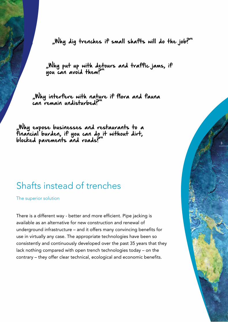
COSTS AT A GLANCE The figure shows the qualitative development of construction costs for open trench and trenchless construction methods as a function of depth. Depending on the existing road surface, the nominal diameter of the pipe, and the groundwater level, a trenchless construction method can be more favorable than an open trench construction meth-od starting at a depth of 3.00 m. In some cases, pipe jacking is more economical, even at lower depths.
cost
s
depth (m)
Open trench construction ID 200 – ID 800
Closed trench construction ID 200 – ID 800
5
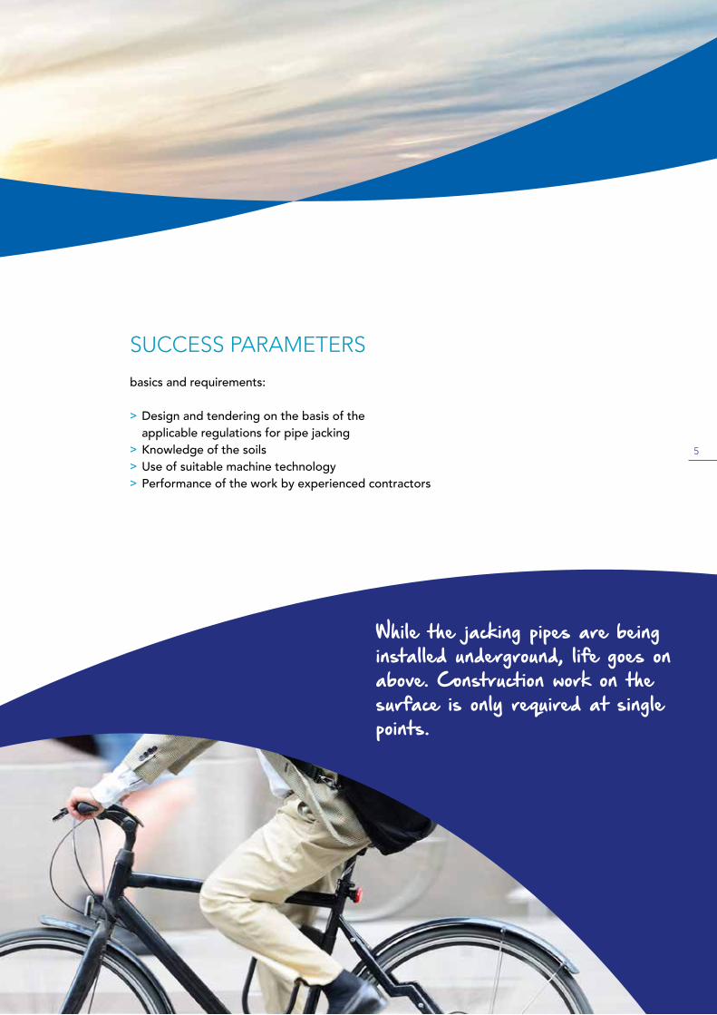
SUCCESS PARAMETERS basics and requirements:
> Design and tendering on the basis of the applicable regulations for pipe jacking
> Knowledge of the soils > Use of suitable machine technology> Performance of the work by experienced contractors
While the jacking pipes are being installed underground, life goes on above. Construction work on the surface is only required at single points.

6
ECONOMIC CONSTRUCTION METHOD+ Multiple use of launch and target shafts for creating sewers and house connections+ Use of the launch and target shafts as maintenance shafts+ Easy checking and inspection through directly connected house connections
ENERGY EFFICIENCY + 90% less soil needs to be transported+ Less or no traffic jams, no detours+ 90% less CO2 emissions/fine dust
SOCIAL / ECONOMIC LIFE+ Low noise levels, minimal vibrations+ Minimal disruption of the technical infrastructure+ Marginal interference with life on the surface thanks to short construction periods
BENEFITS
2„With all of its possible applications and benefits in economic, environmental and social terms, pipe jacking is the best alter-native to open trench construction.“

7
ECONOMIC CONSTRUCTION METHOD+ Multiple use of launch and target shafts for creating sewers and house connections+ Use of the launch and target shafts as maintenance shafts+ Easy checking and inspection through directly connected house connections
ENERGY EFFICIENCY + 90% less soil needs to be transported+ Less or no traffic jams, no detours+ 90% less CO2 emissions/fine dust
SOCIAL / ECONOMIC LIFE+ Low noise levels, minimal vibrations+ Minimal disruption of the technical infrastructure+ Marginal interference with life on the surface thanks to short construction periods
SURFACES+ Road interference only in the area of the start/target shafts+ Minimal impact on nature+ Gentle handling of lateral buildings
GROUNDWATER+ Construction without groundwater lowering
SOIL+ Less soil excavation and landfilling+ No need to replace the soil near the pipeline+ No intermediate storage
MAINTAINING VALUE/LIFETIME+ Up to 50 % longer lifetime thanks to premium building and material quality+ Lower charges thanks to longer amortization period+ Excellent installation precision and ideal bedding of the pipes+ High level of stability thanks to greater wall thickness+ Prevention of settlements
ROADS/TRAFFIC ROUTES+ No reduction in value+ Existing pipes/connections can be underpassed
SAFETY ASPECTS+ High level of safety for construction workers+ Less accidents than in open trench + Less open trenches – more traffic safety
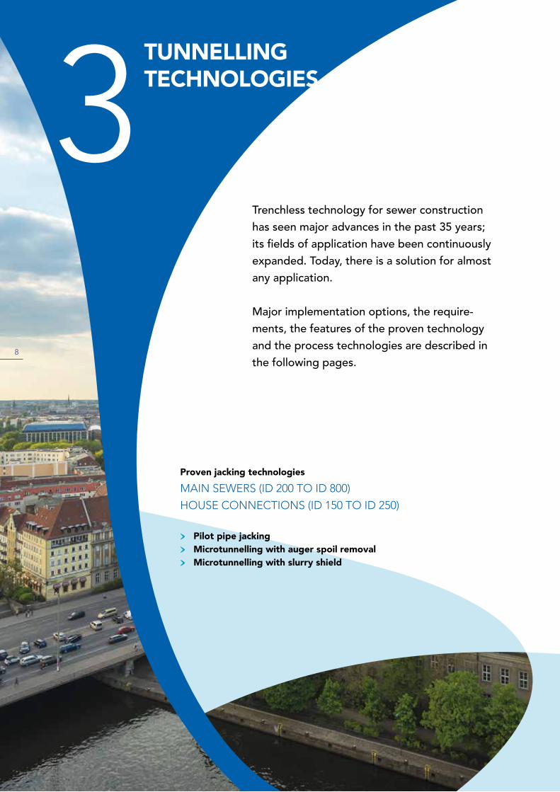
Trenchless technology for sewer construction has seen major advances in the past 35 years; its fields of application have been continuously expanded. Today, there is a solution for almost any application.
Major implementation options, the require-ments, the features of the proven technology and the process technologies are described in the following pages.
TUNNELLING TECHNOLOGIES3
Proven jacking technologies MAIN SEWERS (ID 200 TO ID 800)
HOUSE CONNECTIONS (ID 150 TO ID 250)
> Pilot pipe jacking> Microtunnelling with auger spoil removal> Microtunnelling with slurry shield
8
9
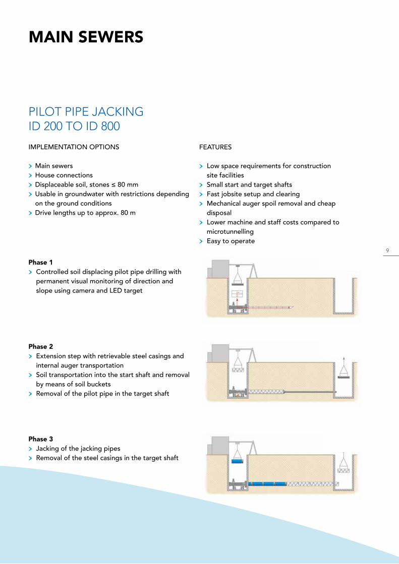
Phase 1> Controlled soil displacing pilot pipe drilling with permanent visual monitoring of direction and slope using camera and LED target
Phase 2> Extension step with retrievable steel casings and internal auger transportation> Soil transportation into the start shaft and removal by means of soil buckets> Removal of the pilot pipe in the target shaft
PILOT PIPE JACKINGID 200 TO ID 800
IMPLEMENTATION OPTIONS
> Main sewers> House connections> Displaceable soil, stones ≤ 80 mm> Usable in groundwater with restrictions depending
on the ground conditions> Drive lengths up to approx. 80 m
MAIN SEWERS
FEATURES
> Low space requirements for construction site facilities> Small start and target shafts> Fast jobsite setup and clearing> Mechanical auger spoil removal and cheap disposal> Lower machine and staff costs compared to microtunnelling> Easy to operate
Phase 3> Jacking of the jacking pipes> Removal of the steel casings in the target shaft
10
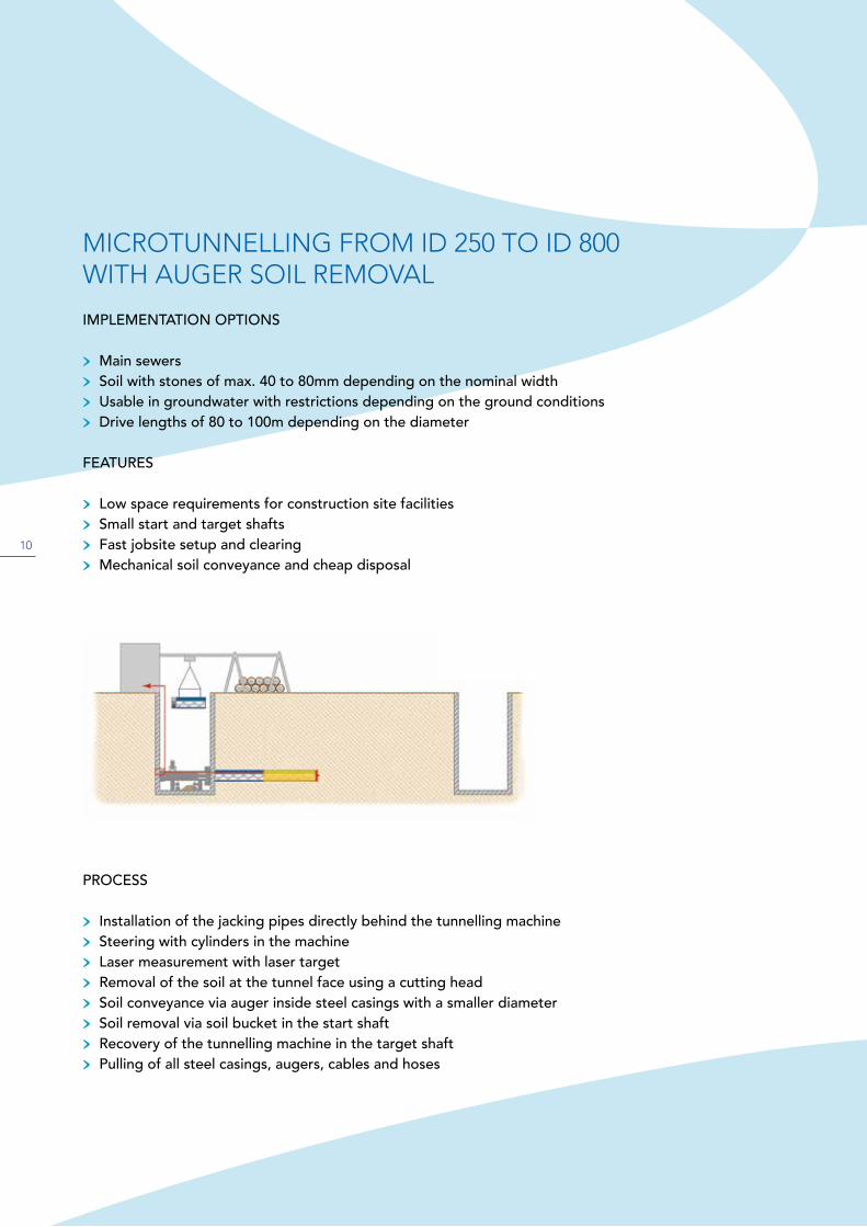
MICROTUNNELLING FROM ID 250 TO ID 800WITH AUGER SOIL REMOVAL
IMPLEMENTATION OPTIONS
> Main sewers> Soil with stones of max. 40 to 80mm depending on the nominal width> Usable in groundwater with restrictions depending on the ground conditions> Drive lengths of 80 to 100m depending on the diameter
FEATURES
> Low space requirements for construction site facilities> Small start and target shafts> Fast jobsite setup and clearing> Mechanical soil conveyance and cheap disposal
PROCESS
> Installation of the jacking pipes directly behind the tunnelling machine> Steering with cylinders in the machine> Laser measurement with laser target> Removal of the soil at the tunnel face using a cutting head> Soil conveyance via auger inside steel casings with a smaller diameter> Soil removal via soil bucket in the start shaft> Recovery of the tunnelling machine in the target shaft> Pulling of all steel casings, augers, cables and hoses
11
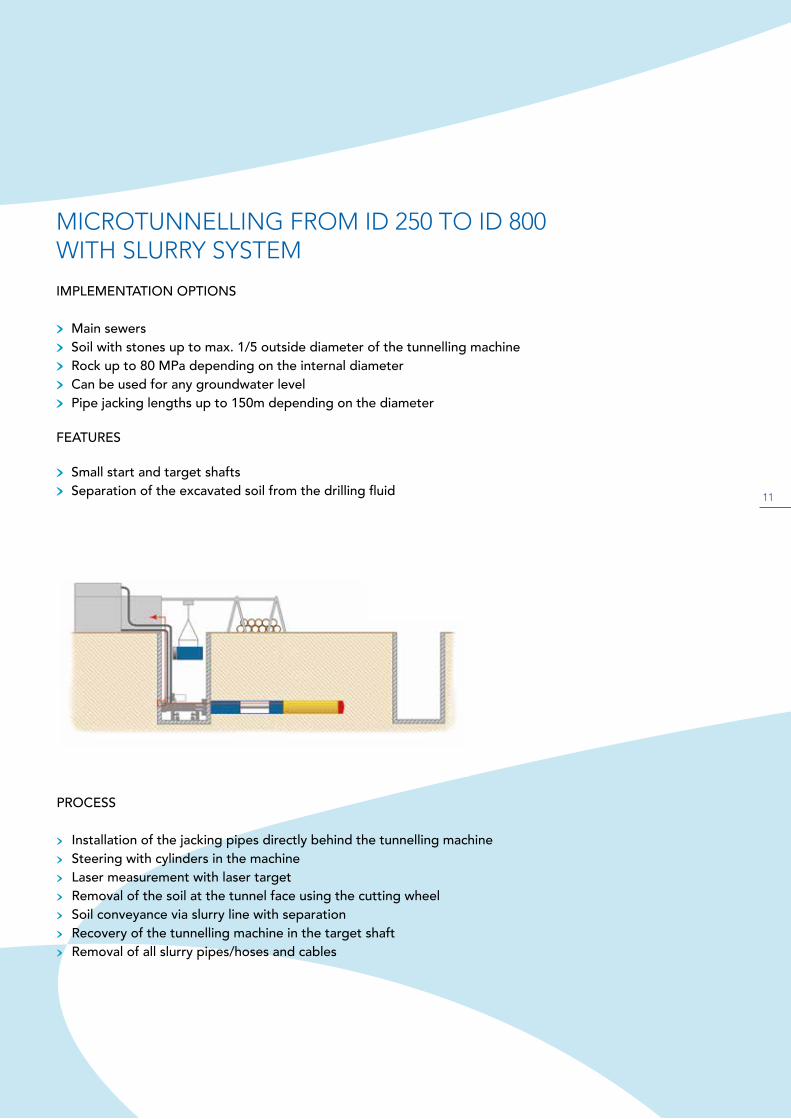
MICROTUNNELLING FROM ID 250 TO ID 800WITH SLURRY SYSTEM
IMPLEMENTATION OPTIONS
> Main sewers> Soil with stones up to max. 1/5 outside diameter of the tunnelling machine> Rock up to 80 MPa depending on the internal diameter> Can be used for any groundwater level> Pipe jacking lengths up to 150m depending on the diameter
FEATURES
> Small start and target shafts> Separation of the excavated soil from the drilling fluid
PROCESS
> Installation of the jacking pipes directly behind the tunnelling machine> Steering with cylinders in the machine> Laser measurement with laser target> Removal of the soil at the tunnel face using the cutting wheel> Soil conveyance via slurry line with separation> Recovery of the tunnelling machine in the target shaft> Removal of all slurry pipes/hoses and cables

12
HOUSE CONNECTIONS
AUGER BORINGMETHOD
PILOT PIPE JACKING
ID 150 TO ID 250
> Uncontrolled method for max. 10m length> Screwed steel casings with augers> After reaching the target shaft, a jacking pipe of the same outer diameter is retroactively jacked
ID 150 TO ID 250
> Pilot pipe jacking by means of controlled tunnelling method from the start to target shaft (See also „Pilot pipe jacking ID 200 to ID 800“; page 9)
13
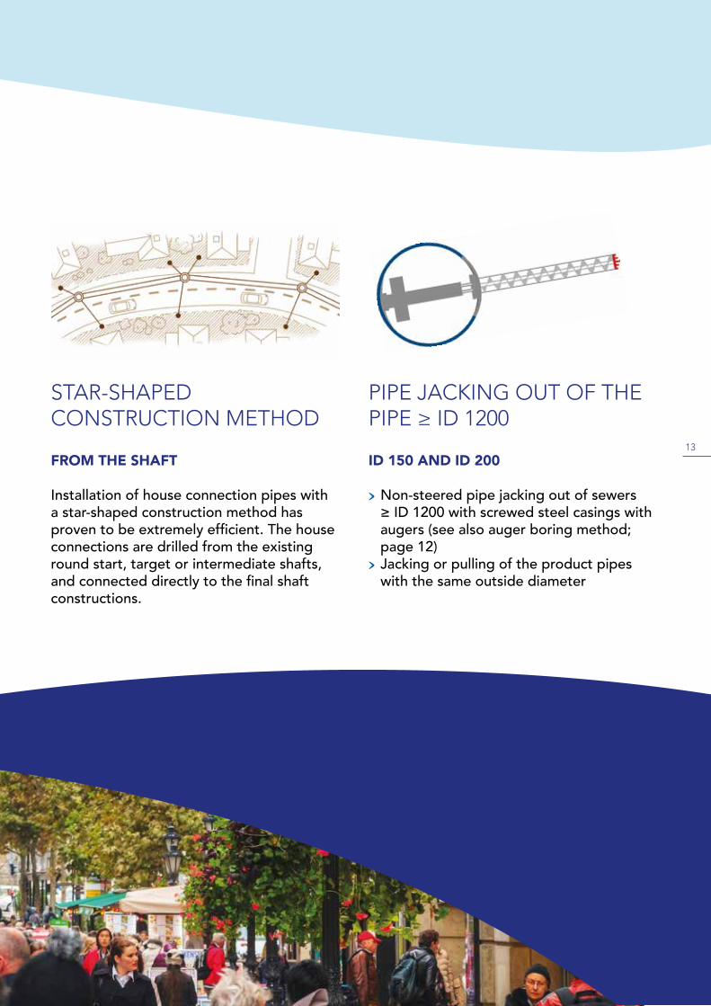
PIPE JACKING OUT OF THE PIPE ≥ ID 1200
STAR-SHAPED CONSTRUCTION METHOD
FROM THE SHAFT
Installation of house connection pipes with a star-shaped construction method has proven to be extremely efficient. The house connections are drilled from the existing round start, target or intermediate shafts, and connected directly to the final shaft constructions.
ID 150 AND ID 200
> Non-steered pipe jacking out of sewers ≥ ID 1200 with screwed steel casings with augers (see also auger boring method; page 12)
> Jacking or pulling of the product pipes with the same outside diameter
14
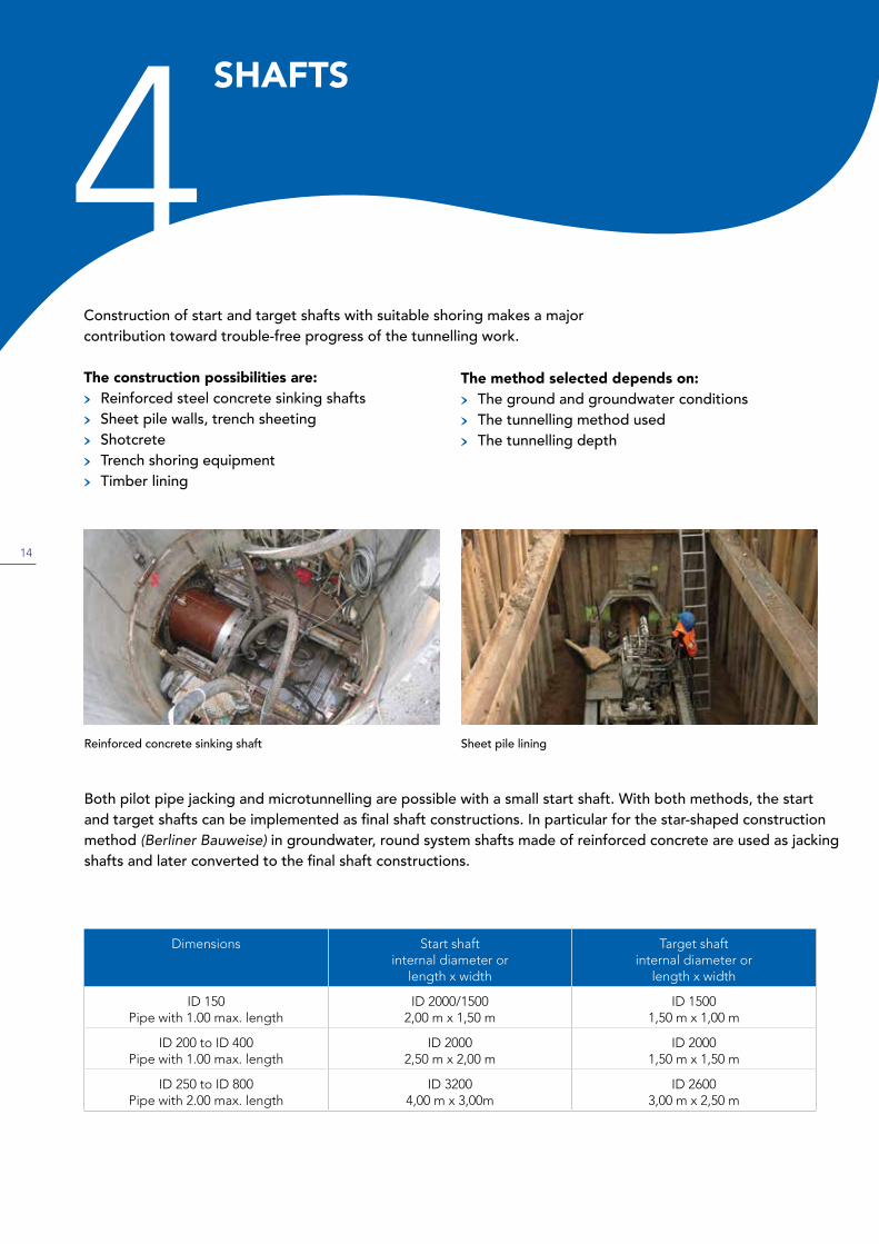
Construction of start and target shafts with suitable shoring makes a major contribution toward trouble-free progress of the tunnelling work.
The construction possibilities are:> Reinforced steel concrete sinking shafts> Sheet pile walls, trench sheeting> Shotcrete> Trench shoring equipment> Timber lining
SHAFTS
4
Sheet pile liningReinforced concrete sinking shaft
Both pilot pipe jacking and microtunnelling are possible with a small start shaft. With both methods, the start and target shafts can be implemented as final shaft constructions. In particular for the star-shaped construction method (Berliner Bauweise) in groundwater, round system shafts made of reinforced concrete are used as jacking shafts and later converted to the final shaft constructions.
Dimensions Start shaft internal diameter or
length x width
Target shaft internal diameter or
length x width
ID 150Pipe with 1.00 max. length
ID 2000/15002,00 m x 1,50 m
ID 15001,50 m x 1,00 m
ID 200 to ID 400Pipe with 1.00 max. length
ID 20002,50 m x 2,00 m
ID 20001,50 m x 1,50 m
ID 250 to ID 800Pipe with 2.00 max. length
ID 32004,00 m x 3,00m
ID 26003,00 m x 2,50 m
The method selected depends on:> The ground and groundwater conditions> The tunnelling method used> The tunnelling depth

15
The benefits and potential applications of pipe jacking have been described in section 1 „Design“ (page 4).
The following table as per GERMAN DWA* RULES AND STANDARDS DWA-A 125E PIPE JACKING AND RELATED TECHNIQUES December 2008 (* German Association for Water, Wastewater and Waste; 53773 Bad Hennef, Germany); provides an overview showing the most important parameters that decide whether pipe jacking technology works or not.
WHAT WORKS ANDWHAT DOESN‘T5
internal diameter
pipe jackinglength
tunnellingin
soil
tunnellingin
rock
tunnelling in
groundwater
ID 150 25m
ID 200 80m
ID 250 90m
ID 300 90m
ID 400 100m
ID 500 120m
ID 600 120m
ID 700 120m
ID 800 150m
works
doesn‘t work
following verification on a case-by-case basis
In internal diameter range up to ID 800 only straight tunnelling is possible.
Removal of obstacles from within the pipe is neither possible nor permissible.

16
PREFACE BY AUTHOR (notes for constructors and planners)
This specification template is designed to provide the author of the draft with instructions on the possible tendering of controlled pipe jacking ID 150 – ID 800. It contains only those RFQ items that are necessary for the actual pipe jacking tendering in view of the author of this guideline.
The most important standards, rulesets, accident prevention regulations, recommendations and contractual provisions to be observed and/or applied are listed under item 3. This specifications template must be individually checked and customized for each case. The author of the draft must edit all points in section 0 „Notes on creating the RFQ specification of the general technical contractual provisions for building services DIN 18299 ff“ as per section 7 para. 1 no. 7 VOB/A (General Local Authorities Code for the Delegation of Building Services) For unmanned, controlled pipe jacking ID 150 – ID 800, this specifically means ATV DIN 18299 and ATV DIN 18319.
Various pipe jacking methods can be suitable for controlled pipe jacking ID 150 – ID 800. The ap-plicability of a specific method is determined by the ground conditions. Notes on this are provided in this guide and in Annex B of worksheet DWA-A 125E. DIN 18319 assigns responsibility for select-ing the pipe jacking method and construction sequence, as well as for providing the construction equipment to the contractor (section 3.1.2.). This approach means that the purchaser can benefit from the special civil engineering company‘s specific experience in this sector without unneces-sarily restricting competition. For this reason, the following RFQ specification template does not use any method designations. However, in individual cases, it may be necessary for the purchaser to define the pipe jacking method. This approach is permissible as per section 0.3.2 DIN 18319. In such a case, the authors recommend calling an recognized expert in this sector to determine the pipe jacking method, or to call in such experts for support.
Surveying and describing the ground in the course of the planning process is a mandatory precon-dition for selecting a suitable pipe jacking method. The basic approach is regulated in sections 2.2 – 2.4 of DIN 18319. The notes in sections 0.2.2 – 0.2.6 and 0.2.8 of DIN 18319 must be observed in addition.
Information 28-1b
17
On publication of the supplementary volume 2015 for VOB 2012, the system of describing the ground in the RFQ documents was changed. The surveyed ground must now be broken down into homogeneous areas as per the respective maintenance group regulations. The properties and characteristics as well as the determined bandwidth must be specified for each ground condition area (homogeneous area). This can be done in the respective RFQ items. For a better overview, the recommendation is to only state the various homogeneous areas, possibly the depth graduations (as per DIN 18300 and 18303 for start, intermediate and target shafts) or length graduations (as per DIN 18319 for pipe jacking work) for each RFQ item, and to list the matching properties and characteristic values in a separate document, which must be marked as a part of the request for quotation.
In addition to performance and reliability, the professional suitability of the bidders for implemen-tation of the pipe jacking work must be verified. RAL GZ 961 paragraph 3.5 or 3.6 can be refer-enced as criteria for this, depending on the quoted pipejacking method.
The items listed in the following relates directly to pipe jacking-specific work. Planners must formu-late additional items, such as acceptance criteria, visual inspection, leakage testing of the compo-nents, etc.

18
TENDER FOR UNMANNED, CONTROLLED PIPE JACKING ID 150 TO ID 800
1. Service description
Preliminary remarks on the specifications DWA-A 161, DWA-A 125 and DIN EN 14457, as well as the respective product standards must be observed for the design of the jacking pipes.
Design of the supporting structure for jacking pipes must be implemented in line with DWA-A 161E.
The planning of the supporting structure and evidence of suitability for purpose must be verified by a qualified test engineer where appropriate. The test report must be submitted to the purchaser two weeks before the scheduled start of the section of the building works in question at the latest. The test engineer‘s fees will be reimbursed on request.
DIN 18319, DIN EN 12889 and DWA-A 125E must be observed in the implementation of the pipe jacking work.
The contractor must have a quality assurance system (in-house and external auditing) in place for the pipe jacking work. Quality assurance in sewer construction RAL-GZ 961 contains a system of this type for implementation section V. The bidder must include the costs of this in the unit costs for controllable pipe jacking. With respect to occupational and health protection of the staff employed, reference is made to DGUV Information Sheet 201-020.
Note for the planner: You may need to add further preliminary remarks here!
19
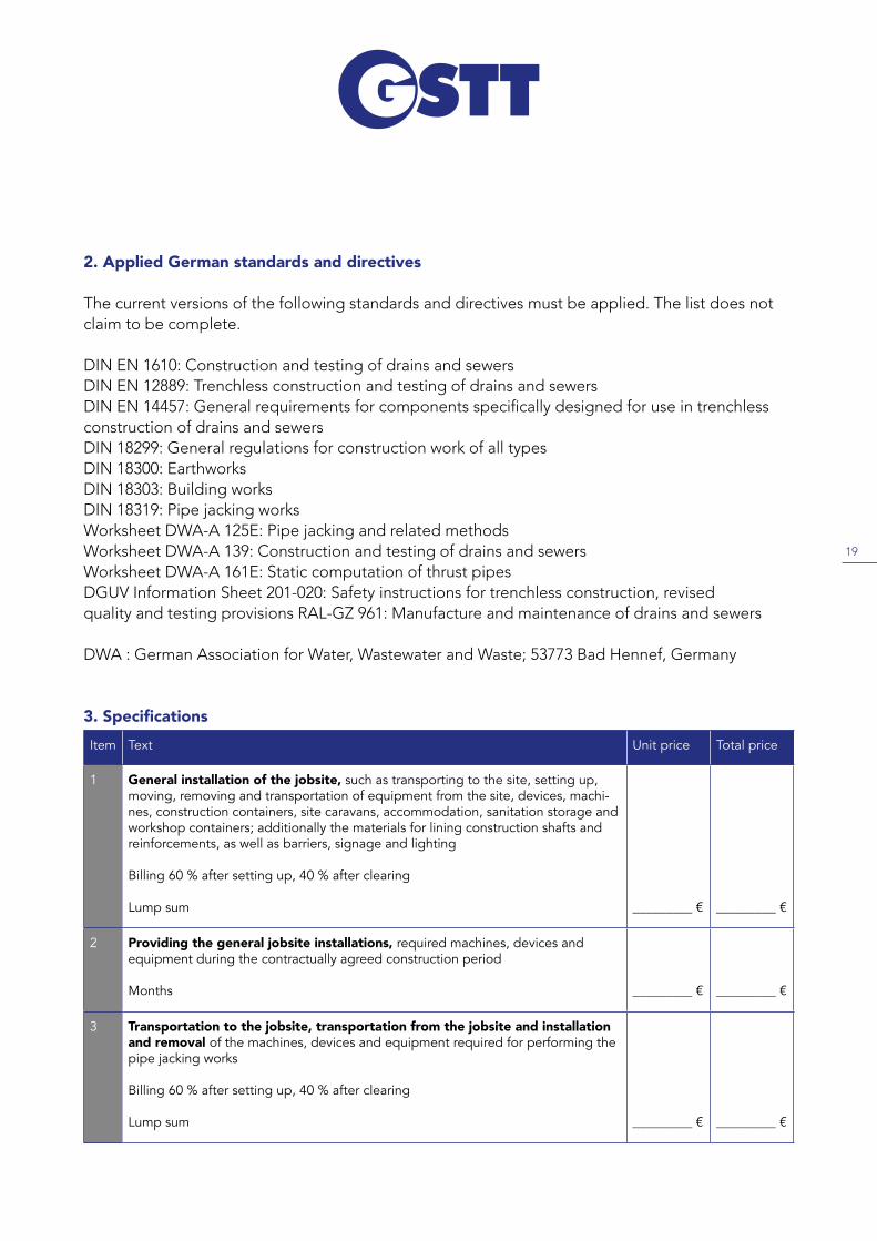
2. Applied German standards and directives
The current versions of the following standards and directives must be applied. The list does not claim to be complete.
DIN EN 1610: Construction and testing of drains and sewersDIN EN 12889: Trenchless construction and testing of drains and sewersDIN EN 14457: General requirements for components specifically designed for use in trenchless construction of drains and sewersDIN 18299: General regulations for construction work of all typesDIN 18300: EarthworksDIN 18303: Building worksDIN 18319: Pipe jacking works Worksheet DWA-A 125E: Pipe jacking and related methodsWorksheet DWA-A 139: Construction and testing of drains and sewersWorksheet DWA-A 161E: Static computation of thrust pipesDGUV Information Sheet 201-020: Safety instructions for trenchless construction, revised quality and testing provisions RAL-GZ 961: Manufacture and maintenance of drains and sewers
DWA : German Association for Water, Wastewater and Waste; 53773 Bad Hennef, Germany
3. SpecificationsItem Text Unit price Total price
1 General installation of the jobsite, such as transporting to the site, setting up, moving, removing and transportation of equipment from the site, devices, machi-nes, construction containers, site caravans, accommodation, sanitation storage and workshop containers; additionally the materials for lining construction shafts and reinforcements, as well as barriers, signage and lighting
Billing 60 % after setting up, 40 % after clearing
Lump sum _________ € _________ €
2 Providing the general jobsite installations, required machines, devices andequipment during the contractually agreed construction period
Months _________ € _________ €
3 Transportation to the jobsite, transportation from the jobsite and installation and removal of the machines, devices and equipment required for performing the pipe jacking works
Billing 60 % after setting up, 40 % after clearing
Lump sum _________ € _________ €

20
Item Text Unit price Total price
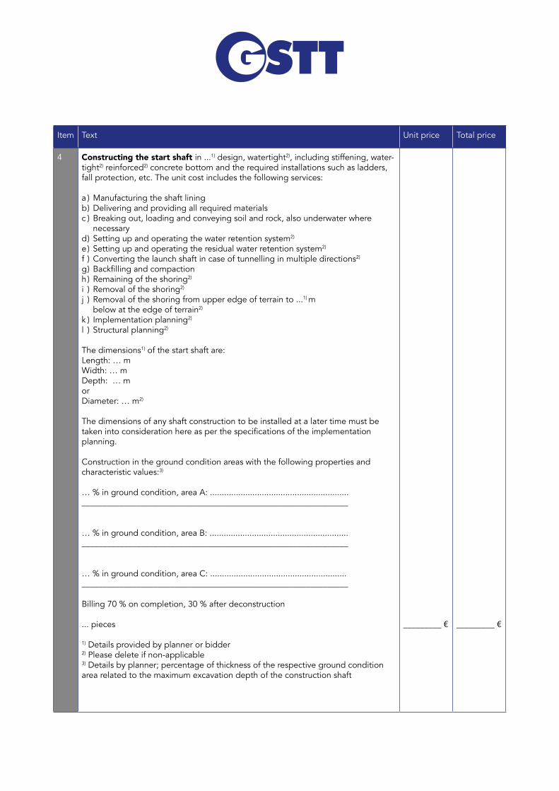
4 Constructing the start shaft in ...1) design, watertight2), including stiffening, water-tight2) reinforced2) concrete bottom and the required installations such as ladders, fall protection, etc. The unit cost includes the following services: a ) Manufacturing the shaft liningb ) Delivering and providing all required materials c ) Breaking out, loading and conveying soil and rock, also underwater where necessaryd ) Setting up and operating the water retention system2)
e ) Setting up and operating the residual water retention system2)
f ) Converting the launch shaft in case of tunnelling in multiple directions2)
g)Backfillingandcompactionh ) Remaining of the shoring2)
i ) Removal of the shoring2)
j ) Removal of the shoring from upper edge of terrain to ...1) m below at the edge of terrain2)
k ) Implementation planning2)
l ) Structural planning2)
The dimensions1) of the start shaft are:Length: … m Width: … mDepth: … morDiameter: … m2)
The dimensions of any shaft construction to be installed at a later time must be takenintoconsiderationhereasperthespecificationsoftheimplementationplanning.
Construction in the ground condition areas with the following properties and characteristic values:3)
… % in ground condition, area A: ..........................................................._______________________________________________________________
… % in ground condition, area B: ..........................................................._______________________________________________________________
… % in ground condition, area C: .........................................................._______________________________________________________________
Billing 70 % on completion, 30 % after deconstruction
... pieces
1) Details provided by planner or bidder2) Please delete if non-applicable3) Details by planner; percentage of thickness of the respective ground condition area related to the maximum excavation depth of the construction shaft
_________ € _________ €
21
Item Text Unit price Total price
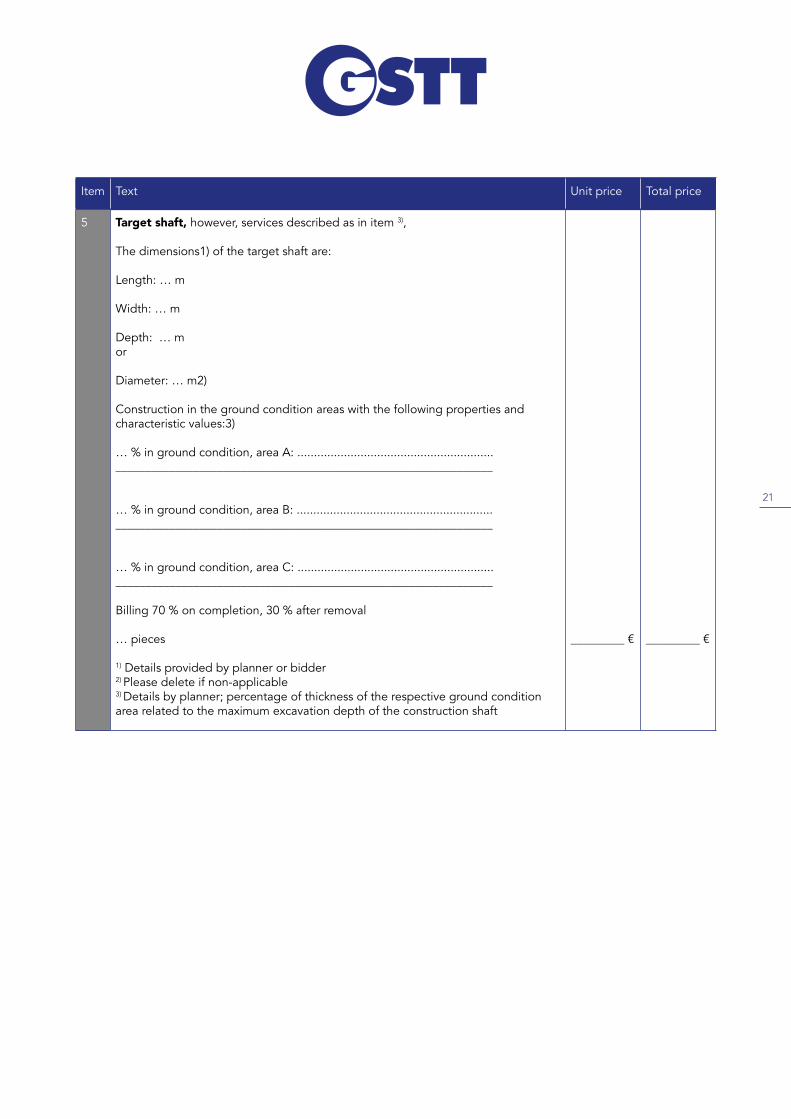
5 Target shaft, however, services described as in item 3),
The dimensions1) of the target shaft are:
Length: … m
Width: … m
Depth: … mor
Diameter: … m2)
Construction in the ground condition areas with the following properties and characteristic values:3)
… % in ground condition, area A: ..........................................................._______________________________________________________________
… % in ground condition, area B: ..........................................................._______________________________________________________________
… % in ground condition, area C: ..........................................................._______________________________________________________________
Billing 70 % on completion, 30 % after removal
… pieces
1) Details provided by planner or bidder2) Please delete if non-applicable3) Details by planner; percentage of thickness of the respective ground condition area related to the maximum excavation depth of the construction shaft
_________ € _________ €
22
Item Text Unit price Total price
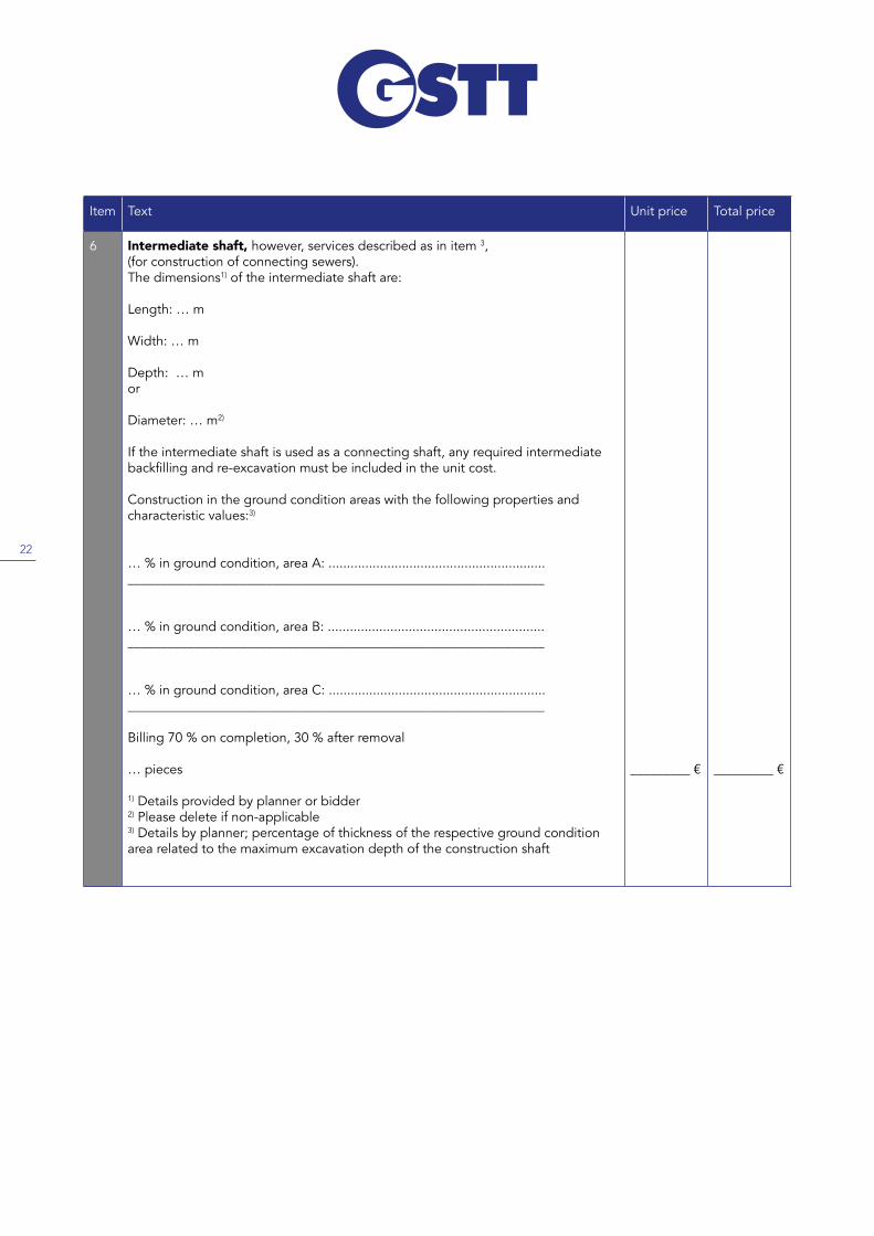
6 Intermediate shaft, however, services described as in item 3, (for construction of connecting sewers).The dimensions1) of the intermediate shaft are:
Length: … m
Width: … m
Depth: … mor
Diameter: … m2)
If the intermediate shaft is used as a connecting shaft, any required intermediate backfillingandre-excavationmustbeincludedintheunitcost.
Construction in the ground condition areas with the following properties and characteristic values:3)
… % in ground condition, area A: ..........................................................._______________________________________________________________
… % in ground condition, area B: ..........................................................._______________________________________________________________
… % in ground condition, area C: ..........................................................._______________________________________________________________
Billing 70 % on completion, 30 % after removal
… pieces
1) Details provided by planner or bidder2) Please delete if non-applicable3) Details by planner; percentage of thickness of the respective ground condition area related to the maximum excavation depth of the construction shaft
_________ € _________ €

23
Item Text Unit price Total price
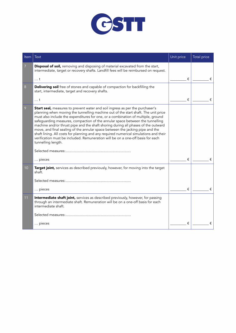
7 Disposal of soil, removing and disposing of material excavated from the start, intermediate,targetorrecoveryshafts.Landfillfeeswillbereimbursedonrequest.
… t _________ € _________ €
8 Delivering soil freeofstonesandcapableofcompactionforbackfillingthe start, intermediate, target and recovery shafts.
… t _________ € _________ €
9 Start seal, measures to prevent water and soil ingress as per the purchaser‘s planning when moving the tunnelling machine out of the start shaft. The unit price must also include the expenditures for one, or a combination of multiple, ground safeguarding measures, compaction of the annular space between the tunnelling machine and/or thrust pipe and the shaft shoring during all phases of the outward move,andfinalsealingoftheannularspacebetweenthejackingpipeandtheshaft lining. All costs for planning and any required numerical simulations and their verificationmustbeincluded.Remunerationwillbeonaone-offbasisforeachtunnelling length.
Selected measures:..................................................................
… pieces _________ € _________ €
10 Target joint, services as described previously, however, for moving into the target shaft.
Selected measures:..................................................................
… pieces _________ € _________ €
11 Intermediate shaft joint, services as described previously, however, for passing through an intermediate shaft. Remuneration will be on a one-off basis for each intermediate shaft.
Selected measures:..................................................................
… pieces _________ € _________ €

24
Item Text Unit price Total price
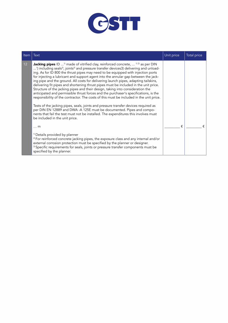
12 Jacking pipes ID ...1)madeofvitrifiedclay,reinforcedconcrete,...1) 2) as per DIN ...1) including seals3), joints3) and pressure transfer devices3) delivering and unload-ing. As for ID 800 the thrust pipes may need to be equipped with injection ports for injecting a lubricant and support agent into the annular gap between the jack-ing pipe and the ground. All costs for delivering launch pipes, adapting tailskins, deliveringfitpipesandshorteningthrustpipesmustbeincludedintheunitprice.Structure of the jacking pipes and their design, taking into consideration the anticipatedandpermissiblethrustforcesandthepurchaser‘sspecifications,istheresponsibility of the contractor. The costs of this must be included in the unit price.
Tests of the jacking pipes, seals, joints and pressure transfer devices required as per DIN EN 12889 and DWA -A 125E must be documented. Pipes and compo-nents that fail the test must not be installed. The expenditures this involves must be included in the unit price.
… m
1) Details provided by planner2) For reinforced concrete jacking pipes, the exposure class and any internal and/or externalcorrosionprotectionmustbespecifiedbytheplannerordesigner.3) Specificrequirementsforseals,jointsorpressuretransfercomponentsmustbespecifiedbytheplanner.
_________ € _________ €
25
Item Text Unit price Total price
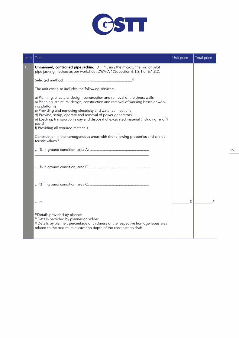
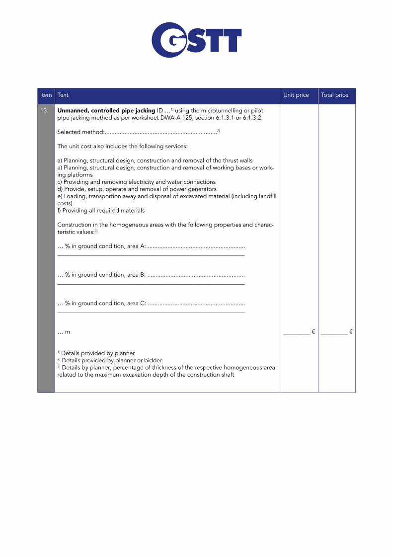
13 Unmanned, controlled pipe jacking ID …1) using the microtunnelling or pilot pipe jacking method as per worksheet DWA-A 125, section 6.1.3.1 or 6.1.3.2.
Selected method:....................................................................2)
The unit cost also includes the following services:
a) Planning, structural design, construction and removal of the thrust wallsa) Planning, structural design, construction and removal of working bases or work-ing platformsc) Providing and removing electricity and water connectionsd) Provide, setup, operate and removal of power generatorse)Loading,transportionawayanddisposalofexcavatedmaterial(includinglandfillcosts)f) Providing all required materials
Construction in the homogeneous areas with the following properties and charac-teristic values:3)
… % in ground condition, area A: ..........................................................._______________________________________________________________
… % in ground condition, area B: ..........................................................._______________________________________________________________
… % in ground condition, area C: ..........................................................._______________________________________________________________
… m
1) Details provided by planner2) Details provided by planner or bidder3) Details by planner; percentage of thickness of the respective homogeneous area related to the maximum excavation depth of the construction shaft
_________ € _________ €
26
Item Text Unit price Total price
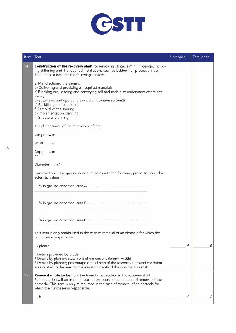
14 Construction of the recovery shaft for removing obstacles2) in ...1) design, includ-ing stiffening and the required installations such as ladders, fall protection, etc. The unit cost includes the following services:
a) Manufacturing the shoringb) Delivering and providing all required materials c) Breaking out, loading and conveying soil and rock, also underwater where nec-essaryd) Setting up and operating the water retention system2) e)Backfillingandcompactionf) Removal of the shoringg) Implementation planningh) Structural planning
The dimensions1) of the recovery shaft are:
Length: … m
Width: … m
Depth: … mor
Diameter: … m1)
Construction in the ground condition areas with the following properties and char-acteristic values:3)
… % in ground condition, area A: ..........................................................._______________________________________________________________
… % in ground condition, area B: ..........................................................._______________________________________________________________
… % in ground condition, area C: ..........................................................._______________________________________________________________
This item is only reimbursed in the case of removal of an obstacle for which the purchaser is responsible.
… pieces
1) Details provided by bidder2) Details by planner; statement of dimensions (length, width)3) Details by planner; percentage of thickness of the respective ground condition area related to the maximum excavation depth of the construction shaft
_________ € _________ €
15 Removal of obstacles from the tunnel cross section in the recovery shaft. Remuneration will be from the start of exposure to completion of removal of the obstacle. This item is only reimbursed in the case of removal of an obstacle for which the purchaser is responsible.
… h _________ € _________ €
27
Item Text Unit price Total price
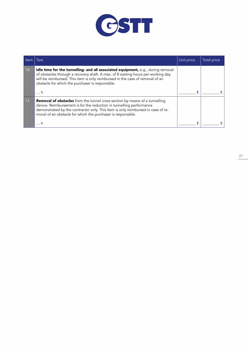
16 Idle time for the tunnelling- and all associated equipment, e.g., during removal of obstacles through a recovery shaft. A max. of 8 waiting hours per working day will be reimbursed. This item is only reimbursed in the case of removal of an obstacle for which the purchaser is responsible. … h _________ € _________ €
17 Removal of obstacles from the tunnel cross section by means of a tunnellingdevice. Reimbursement is for the reduction in tunnelling performance demonstrated by the contractor only. This item is only reimbursed in case of re-moval of an obstacle for which the purchaser is responsible.
… h _________ € _________ €
www.gstt.de
The current specifications template is available on our website as a Word document or PDF.
PREFACE BY AUTHOR (notes for constructors and planners)
This specification template is designed to provide the author of the draft with instructions on the possible tendering of controlled pipe jacking ID 150 – ID 800. It contains only those RFQ items that are necessary for the actual pipe jacking tendering in view of the author of this guideline.
The most important standards, rulesets, accident prevention regulations, recommendations and contractual provisions to be observed and/or applied are listed under item 3. This specifications template must be individually checked and customized for each case. The author of the draft must edit all points in section 0 „Notes on creating the RFQ specification of the general technical contractual provisions for building services DIN 18299 ff“ as per section 7 para. 1 no. 7 VOB/A (General Local Authorities Code for the Delegation of Building Services) For unmanned, controlled pipe jacking ID 150 – ID 800, this specifically means ATV DIN 18299 and ATV DIN 18319.
Various pipe jacking methods can be suitable for controlled pipe jacking ID 150 – ID 800. The ap-plicability of a specific method is determined by the ground conditions. Notes on this are provided in this guide and in Annex B of worksheet DWA-A 125E. DIN 18319 assigns responsibility for select-ing the pipe jacking method and construction sequence, as well as for providing the construction equipment to the contractor (section 3.1.2.). This approach means that the purchaser can benefit from the special civil engineering company‘s specific experience in this sector without unneces-sarily restricting competition. For this reason, the following RFQ specification template does not use any method designations. However, in individual cases, it may be necessary for the purchaser to define the pipe jacking method. This approach is permissible as per section 0.3.2 DIN 18319. In such a case, the authors recommend calling an recognized expert in this sector to determine the pipe jacking method, or to call in such experts for support.
Surveying and describing the ground in the course of the planning process is a mandatory precon-dition for selecting a suitable pipe jacking method. The basic approach is regulated in sections 2.2 – 2.4 of DIN 18319. The notes in sections 0.2.2 – 0.2.6 and 0.2.8 of DIN 18319 must be observed in addition.
Information 28-1b
On publication of the supplementary volume 2015 for VOB 2012, the system of describing the ground in the RFQ documents was changed. The surveyed ground must now be broken down into homogeneous areas as per the respective maintenance group regulations. The properties and characteristics as well as the determined bandwidth must be specified for each ground condition area (homogeneous area). This can be done in the respective RFQ items. For a better overview, the recommendation is to only state the various homogeneous areas, possibly the depth graduations (as per DIN 18300 and 18303 for start, intermediate and target shafts) or length graduations (as per DIN 18319 for pipe jacking work) for each RFQ item, and to list the matching properties and characteristic values in a separate document, which must be marked as a part of the request for quotation.
In addition to performance and reliability, the professional suitability of the bidders for implemen-tation of the pipe jacking work must be verified. RAL GZ 961 paragraph 3.5 or 3.6 can be refer-enced as criteria for this, depending on the quoted pipejacking method.
The items listed in the following relates directly to pipe jacking-specific work. Planners must formu-late additional items, such as acceptance criteria, visual inspection, leakage testing of the compo-nents, etc.
TENDER FOR UNMANNED, CONTROLLED PIPE JACKING ID 150 TO ID 800
1. Service description
Preliminary remarks on the specifications DWA-A 161, DWA-A 125 and DIN EN 14457, as well as the respective product standards must be observed for the design of the jacking pipes.
Design of the supporting structure for jacking pipes must be implemented in line with DWA-A 161E.
The planning of the supporting structure and evidence of suitability for purpose must be verified by a qualified test engineer where appropriate. The test report must be submitted to the purchaser two weeks before the scheduled start of the section of the building works in question at the latest. The test engineer‘s fees will be reimbursed on request.
DIN 18319, DIN EN 12889 and DWA-A 125E must be observed in the implementation of the pipe jacking work.
The contractor must have a quality assurance system (in-house and external auditing) in place for the pipe jacking work. Quality assurance in sewer construction RAL-GZ 961 contains a system of this type for implementation section V. The bidder must include the costs of this in the unit costs for controllable pipe jacking. With respect to occupational and health protection of the staff employed, reference is made to DGUV Information Sheet 201-020.
Note for the planner: You may need to add further preliminary remarks here!

2. Applied German standards and directives
The current versions of the following standards and directives must be applied. The list does not claim to be complete.
DIN EN 1610: Construction and testing of drains and sewersDIN EN 12889: Trenchless construction and testing of drains and sewersDIN EN 14457: General requirements for components specifically designed for use in trenchless construction of drains and sewersDIN 18299: General regulations for construction work of all typesDIN 18300: EarthworksDIN 18303: Building worksDIN 18319: Pipe jacking works Worksheet DWA-A 125E: Pipe jacking and related methodsWorksheet DWA-A 139: Construction and testing of drains and sewersWorksheet DWA-A 161E: Static computation of thrust pipesDGUV Information Sheet 201-020: Safety instructions for trenchless construction, revised quality and testing provisions RAL-GZ 961: Manufacture and maintenance of drains and sewers
DWA : German Association for Water, Wastewater and Waste; 53773 Bad Hennef, Germany
3. SpecificationsItem Text Unit price Total price
1 General installation of the jobsite, such as transporting to the site, setting up, moving, removing and transportation of equipment from the site, devices, machi-nes, construction containers, site caravans, accommodation, sanitation storage and workshop containers; additionally the materials for lining construction shafts and reinforcements, as well as barriers, signage and lighting
Billing 60 % after setting up, 40 % after clearing
Lump sum _________ € _________ €
2 Providing the general jobsite installations, required machines, devices andequipment during the contractually agreed construction period
Months _________ € _________ €
3 Transportation to the jobsite, transportation from the jobsite and installation and removal of the machines, devices and equipment required for performing the pipe jacking works
Billing 60 % after setting up, 40 % after clearing
Lump sum _________ € _________ €
Item Text Unit price Total price
4 Constructing the start shaft in ...1) design, watertight2), including stiffening, water-tight2) reinforced2) concrete bottom and the required installations such as ladders, fall protection, etc. The unit cost includes the following services: a ) Manufacturing the shaft liningb ) Delivering and providing all required materials c ) Breaking out, loading and conveying soil and rock, also underwater where necessaryd ) Setting up and operating the water retention system2)
e ) Setting up and operating the residual water retention system2)
f ) Converting the launch shaft in case of tunnelling in multiple directions2)
g)Backfillingandcompactionh ) Remaining of the shoring2)
i ) Removal of the shoring2)
j ) Removal of the shoring from upper edge of terrain to ...1) m below at the edge of terrain2)
k ) Implementation planning2)
l ) Structural planning2)
The dimensions1) of the start shaft are:Length: … m Width: … mDepth: … morDiameter: … m2)
The dimensions of any shaft construction to be installed at a later time must be takenintoconsiderationhereasperthespecificationsoftheimplementationplanning.
Construction in the ground condition areas with the following properties and characteristic values:3)
… % in ground condition, area A: ..........................................................._______________________________________________________________
… % in ground condition, area B: ..........................................................._______________________________________________________________
… % in ground condition, area C: .........................................................._______________________________________________________________
Billing 70 % on completion, 30 % after deconstruction
... pieces
1) Details provided by planner or bidder2) Please delete if non-applicable3) Details by planner; percentage of thickness of the respective ground condition area related to the maximum excavation depth of the construction shaft
_________ € _________ €

Item Text Unit price Total price
5 Target shaft, however, services described as in item 3),
The dimensions1) of the target shaft are:
Length: … m
Width: … m
Depth: … mor
Diameter: … m2)
Construction in the ground condition areas with the following properties and characteristic values:3)
… % in ground condition, area A: ..........................................................._______________________________________________________________
… % in ground condition, area B: ..........................................................._______________________________________________________________
… % in ground condition, area C: ..........................................................._______________________________________________________________
Billing 70 % on completion, 30 % after removal
… pieces
1) Details provided by planner or bidder2) Please delete if non-applicable3) Details by planner; percentage of thickness of the respective ground condition area related to the maximum excavation depth of the construction shaft
_________ € _________ €

Item Text Unit price Total price
6 Intermediate shaft, however, services described as in item 3, (for construction of connecting sewers).The dimensions1) of the intermediate shaft are:
Length: … m
Width: … m
Depth: … mor
Diameter: … m2)
If the intermediate shaft is used as a connecting shaft, any required intermediate backfillingandre-excavationmustbeincludedintheunitcost.
Construction in the ground condition areas with the following properties and characteristic values:3)
… % in ground condition, area A: ..........................................................._______________________________________________________________
… % in ground condition, area B: ..........................................................._______________________________________________________________
… % in ground condition, area C: ..........................................................._______________________________________________________________
Billing 70 % on completion, 30 % after removal
… pieces
1) Details provided by planner or bidder2) Please delete if non-applicable3) Details by planner; percentage of thickness of the respective ground condition area related to the maximum excavation depth of the construction shaft
_________ € _________ €
Item Text Unit price Total price
7 Disposal of soil, removing and disposing of material excavated from the start, intermediate,targetorrecoveryshafts.Landfillfeeswillbereimbursedonrequest.
… t _________ € _________ €
8 Delivering soil freeofstonesandcapableofcompactionforbackfillingthe start, intermediate, target and recovery shafts.
… t _________ € _________ €
9 Start seal, measures to prevent water and soil ingress as per the purchaser‘s planning when moving the tunnelling machine out of the start shaft. The unit price must also include the expenditures for one, or a combination of multiple, ground safeguarding measures, compaction of the annular space between the tunnelling machine and/or thrust pipe and the shaft shoring during all phases of the outward move,andfinalsealingoftheannularspacebetweenthejackingpipeandtheshaft lining. All costs for planning and any required numerical simulations and their verificationmustbeincluded.Remunerationwillbeonaone-offbasisforeachtunnelling length.
Selected measures:..................................................................
… pieces _________ € _________ €
10 Target joint, services as described previously, however, for moving into the target shaft.
Selected measures:..................................................................
… pieces _________ € _________ €
11 Intermediate shaft joint, services as described previously, however, for passing through an intermediate shaft. Remuneration will be on a one-off basis for each intermediate shaft.
Selected measures:..................................................................
… pieces _________ € _________ €
Item Text Unit price Total price
12 Jacking pipes ID ...1)madeofvitrifiedclay,reinforcedconcrete,...1) 2) as per DIN ...1) including seals3), joints3) and pressure transfer devices3) delivering and unload-ing. As for ID 800 the thrust pipes may need to be equipped with injection ports for injecting a lubricant and support agent into the annular gap between the jack-ing pipe and the ground. All costs for delivering launch pipes, adapting tailskins, deliveringfitpipesandshorteningthrustpipesmustbeincludedintheunitprice.Structure of the jacking pipes and their design, taking into consideration the anticipatedandpermissiblethrustforcesandthepurchaser‘sspecifications,istheresponsibility of the contractor. The costs of this must be included in the unit price.
Tests of the jacking pipes, seals, joints and pressure transfer devices required as per DIN EN 12889 and DWA -A 125E must be documented. Pipes and compo-nents that fail the test must not be installed. The expenditures this involves must be included in the unit price.
… m
1) Details provided by planner2) For reinforced concrete jacking pipes, the exposure class and any internal and/or externalcorrosionprotectionmustbespecifiedbytheplannerordesigner.3) Specificrequirementsforseals,jointsorpressuretransfercomponentsmustbespecifiedbytheplanner.
_________ € _________ €
Item Text Unit price Total price
13 Unmanned, controlled pipe jacking ID …1) using the microtunnelling or pilot pipe jacking method as per worksheet DWA-A 125, section 6.1.3.1 or 6.1.3.2.
Selected method:....................................................................2)
The unit cost also includes the following services:
a) Planning, structural design, construction and removal of the thrust wallsa) Planning, structural design, construction and removal of working bases or work-ing platformsc) Providing and removing electricity and water connectionsd) Provide, setup, operate and removal of power generatorse)Loading,transportionawayanddisposalofexcavatedmaterial(includinglandfillcosts)f) Providing all required materials
Construction in the homogeneous areas with the following properties and charac-teristic values:3)
… % in ground condition, area A: ..........................................................._______________________________________________________________
… % in ground condition, area B: ..........................................................._______________________________________________________________
… % in ground condition, area C: ..........................................................._______________________________________________________________
… m
1) Details provided by planner2) Details provided by planner or bidder3) Details by planner; percentage of thickness of the respective homogeneous area related to the maximum excavation depth of the construction shaft
_________ € _________ €

Item Text Unit price Total price
14 Construction of the recovery shaft for removing obstacles2) in ...1) design, includ-ing stiffening and the required installations such as ladders, fall protection, etc. The unit cost includes the following services:
a) Manufacturing the shoringb) Delivering and providing all required materials c) Breaking out, loading and conveying soil and rock, also underwater where nec-essaryd) Setting up and operating the water retention system2) e)Backfillingandcompactionf) Removal of the shoringg) Implementation planningh) Structural planning
The dimensions1) of the recovery shaft are:
Length: … m
Width: … m
Depth: … mor
Diameter: … m1)
Construction in the ground condition areas with the following properties and char-acteristic values:3)
… % in ground condition, area A: ..........................................................._______________________________________________________________
… % in ground condition, area B: ..........................................................._______________________________________________________________
… % in ground condition, area C: ..........................................................._______________________________________________________________
This item is only reimbursed in the case of removal of an obstacle for which the purchaser is responsible.
… pieces
1) Details provided by bidder2) Details by planner; statement of dimensions (length, width)3) Details by planner; percentage of thickness of the respective ground condition area related to the maximum excavation depth of the construction shaft
_________ € _________ €
15 Removal of obstacles from the tunnel cross section in the recovery shaft. Remuneration will be from the start of exposure to completion of removal of the obstacle. This item is only reimbursed in the case of removal of an obstacle for which the purchaser is responsible.
… h _________ € _________ €

Item Text Unit price Total price
16 Idle time for the tunnelling- and all associated equipment, e.g., during removal of obstacles through a recovery shaft. A max. of 8 waiting hours per working day will be reimbursed. This item is only reimbursed in the case of removal of an obstacle for which the purchaser is responsible. … h _________ € _________ €
17 Removal of obstacles from the tunnel cross section by means of a tunnellingdevice. Reimbursement is for the reduction in tunnelling performance demonstrated by the contractor only. This item is only reimbursed in case of re-moval of an obstacle for which the purchaser is responsible.
… h _________ € _________ €