info@mjmyachts · 401-862-4367 [email protected] July 2016 Dear 40z Owner: Congratulations on...
70
401-862-4367 [email protected] July 2016 Dear 40z Owner: Congratulations on becoming Captain and Owner of the world’s best built and most eco-friendly yacht of its size. The enclosed copy of the 40z Owner’s Manual should further contribute to your enjoyment and proficiency afloat. This manual was created jointly with Zurn Yacht Design, Boston BoatWorks and MJM Yachts. Our experience with the first 200 boats (all models included) is included to make this manual as useful and relevant as possible. Keep in mind there will be some variances or custom additions to your boat, which wont’ be separately detailed in this manual. And, from time-to-time we will change specifications to keep pace with changes made to improve the boats. When addressing a problem with a specific piece of equipment, this 40z Owner’s Manual is to be regarded only as a preliminary source of information. The equipment manufacturer’s own manual with trouble-shooting procedures, etc. is the primary source and authority. A Small Craft Owner’s Manual accompanies, and forms part of, this 40z Owner Manual. This booklet has universal handling and operating tips worth reviewing. This 40z Owner’s Manual is designed to be a living document, not only for builder updates but for your own use and record. Each boat is provided with a copy of the current Manual organized in a STAPLES “Mini-Ring” type binder that allows you to add pages as needed. One of the great advantages of purchasing a series-built or semi-custom design is that owners have the benefit of learning from one another. So, with your continued input and comments we can keep adding useful information and helpful hints to this manual. Part of the ISO CE Mark Certification Program is confirmation by the owner that the manual has been received. Please sign the extra page No. 3 included in the Manual as a receipt and return it in the stamped envelope provided. Best wishes for fair winds and sunny skies. On behalf of the builder and designer, we are most appreciative, and I am particularly honored, that you have chosen the MJM Yachts 40z. Robert L. Johnstone Founder & CEO Note: This manual is published in accordance with ISO standard 10240:1995E Small Craft - Owner’s Manual
Transcript of info@mjmyachts · 401-862-4367 [email protected] July 2016 Dear 40z Owner: Congratulations on...

401-862-4367 [email protected]
July 2016 Dear 40z Owner:
Congratulations on becoming Captain and Owner of the world’s best built and most eco-friendly yacht of its size. The enclosed copy of the 40z Owner’s Manual should further contribute to your enjoyment and proficiency afloat. This manual was created jointly with Zurn Yacht Design, Boston BoatWorks and MJM Yachts. Our experience with the first 200 boats (all models included) is included to make this manual as useful and relevant as possible. Keep in mind there will be some variances or custom additions to your boat, which wont’ be separately detailed in this manual. And, from time-to-time we will change specifications to keep pace with changes made to improve the boats. When addressing a problem with a specific piece of equipment, this 40z Owner’s Manual is to be regarded only as a preliminary source of information. The equipment manufacturer’s own manual with trouble-shooting procedures, etc. is the primary source and authority. A Small Craft Owner’s Manual accompanies, and forms part of, this 40z Owner Manual. This booklet has universal handling and operating tips worth reviewing. This 40z Owner’s Manual is designed to be a living document, not only for builder updates but for your own use and record. Each boat is provided with a copy of the current Manual organized in a STAPLES “Mini-Ring” type binder that allows you to add pages as needed. One of the great advantages of purchasing a series-built or semi-custom design is that owners have the benefit of learning from one another. So, with your continued input and comments we can keep adding useful information and helpful hints to this manual. Part of the ISO CE Mark Certification Program is confirmation by the owner that the manual has been received. Please sign the extra page No. 3 included in the Manual as a receipt and return it in the stamped envelope provided. Best wishes for fair winds and sunny skies. On behalf of the builder and designer, we are most appreciative, and I am particularly honored, that you have chosen the MJM Yachts 40z.
Robert L. Johnstone Founder & CEO
Note: This manual is published in accordance with ISO standard 10240:1995E Small Craft - Owner’s Manual

40z Owner’s Manual
LOA - Length Overall Including Swim Platform & Bow Roller 44.3 ft. LOD - Length On Deck 40.0 ft Beam – Trailerable Max Width 12.0 ft. Draft – Max Draft with IPS or Stern Drives Down 3.3 ft. Displacement – ½ Load 18,900 lbs. Fuel Tankage - In 2 175 gallon Tanks 350 gals. Fresh Water Tankage – Including Hot Water Tank 112 gals. Holding Tank 25 gals. Air Height over Water w/Radar Mounted on Hard Top 10.0 ft

CE CERTIFICATION CERTIFICATE NO.
ADDRESS:
WEBSITE: CLASSIFICATION:
CAPACITY PERSONS: PERSONS/GEAR:
-------------------------------------------------------------------------------------------------------------------------------------------- RECEIPT BY OWNER In compliance with ISO 10240:1995(E) the owner hereby certifies receipt of this manual and has read and agrees to the terms of the Builder’s Limited Warranty included herein.
Signature
Printed Name
Boat Name
Address
City, State, Zip
Tel.
E Mail
NOTE: PLEASE SIGN ONE OF THE TWO COPIES OF THIS PAGE AND RETURN IT IN THE ATTACHED STAMPED ENVELOPE TO: MJM YACHTS at 39 Washington St. Newport RI 02840
Denotes an extreme intrinsic hazard exits which would result in high probability of death or irreparable injury if proper precautions are not taken.
Denotes a hazard exists which can result in injury or death if proper precautions are not taken.
Denotes a reminder of safety practices or directs attention to unsafe practices
which could result in personal injury or damage to the craft or components.
- 4 -
International Marine Certification Institute Rue Abbe Cuypers 3 B-1040 Bruxelles, Belgique +32-2-741-2418
ISO CE Mark Design Category A Ocean (EC Directive 94/25/EC) for craft designed for offshore voyages (1) where the vessel is correctly handled in the sense of good seamanship and operated at a speed appropriate to the prevailing sea state and (2) with significant wave heights above 4 m (calculations are based on 7 m) and wind speeds in excess of Beaufort Force 8, but excluding abnormal conditions, e.g. hurricanes.
Maximum 16 Persons Maximum Load 3518 kg
Hull #
Date
AUTHORITY: BBBW003
PHONE: www.imci.org
NAME:
ADDRESS:
MOBILE

! !!!!!!!!!!!!!!!!!!!!TABLE!OF!CONTENTS
CHAPTER(1( OPERATION CHAPTER(7 FRESH(WATER(SYSTEM1.1 General 7 General
1.2 Quick!Start!(See!Chapter!16) 7.1 Filling
1.3 Operating!Procedures 7.2 Fresh!Water!Pump
1.4 Navigation 7.3 Hot!Water
1.5 Hauling!Out 7.4 Water!Purifier
CHAPTER(2 SAFETY(EQUIPMENT CHAPTER(8 RAW(WATER(SYSTEM2.1 General 8.1 General
2.2 Fuel!ShutOOffs 8.2 Engine!Raw!Water!Strainer
2.3 Fire CHAPTER(9 GRAY(WATER(SYSTEMCHAPTER(3 PROPULSION(SYSTEM 9.1 General
Intro Top!10!Reasons!of!Engine!Failure 9.2 Gray!Water!Sumps
3.1 General 9.3 Bilge!Pumps
3.2 Cooling 9.4 Common!Drains
3.3 Lubrication CHAPTER(10 SYSTEMS(&(EQUIPMENT3.4 Corrosion!Protection 10.1 Seakeeper!Gyro!Stabilizer
3.5 Air!Intakes 10.2 Anchor!Windlass!&!Washdown
3.6 Engine!Data!Display 10.3 Pilothouse!Curtains
3.7 Engine!Control!Levers 10.4 Privacy!&!Sunscreen!Curtains
3.8 Start!&!Failure!Reboot 10.5 Transom!Door!&!Seat
3.9 Alarms 10.6 Stidd!Seat!Positions
3.10 Stopping 10.7 Windshield!Operation
3.11 Operation CHAPTER(11 INTERIOR(EQUIPMENTCHAPTER(4 STEERING(SYSTEM 11.1 Vacuflush!Heads
4.1 System 11.2 Refrigeration
4.2 IPS!Joystick!Docking 11.3 Cooktop
4.3 Helm!Station 11.4 Oven
4.4 Switch!Panel 11.5 Air!Conditioning
4.5 Trim!Tabs 11.6 Wallas!Diesel!Heater
4.6 Autopilot 11.7 Fusion!Stereo
4.7 Windshield!Wipers 11.8 Sirius!Satellite!Radio
4.8 Spotlight 11.9 LED!TVs
4.9 Docking/Headlights! 11.10 KVH!Satellite!TV
4.1 Helm!Position!Riser CHAPTER(12 ROUTINE(MAINTENANCECHAPTER(5 FUEL(SYSTEM 12.1 Schedule
5 General CHAPTER(13 SEASONAL(MAINTENANCE5.1 Fuel!Shut!Offs 13.1 Start!of!Season
5.2 Filling 13.2 End!of!Season
5.3 Racor!Fuel!Filters
5.4 Fuel!Consumption!Log CHAPTER(14 SCHEMATICSCHAPTER(6 ELECTRICAL(SYSTEM 14.1 Emergency!Diagram
6 General 14.2 12!Volt!DC!Schematic
6.1 Electical!Panels 14.3 120V/240V!AC!Schematic
6.2 AC!Shorepower 14.4 Systems!Diagram
6.3 Generator 14.5 Systems!Key
6.4 Inverter 14.6 Boat!Lift!&!Bunk!Offsets
6.5 Charging 14.7 Trailer!Loading!Checklist
6.6 Reverse!Polarity CHAPTER(15 LIMITED(WARRANTY6.7 Electrolysis!&!Galvanic!Corrosion CHAPTEr(16 QUICK(START(GUIDE6.8 Bonding
6.9 Electrical!Safety
1.1
1.2
1.3
1.4
OPERATION GENERAL
This manual has been compiled to help you operate your yacht with safety and pleasure. It contains details of the yacht; the equipment supplied or fitted, its systems, and information on its operation and maintenance. Please read it carefully, and familiarize yourself with the yacht before using it. If this is your first yacht, or you are changing to a type of yacht you are not familiar with, for your own comfort and safety, please insure that you obtain handling and operating experience before assuming command of the yacht. Your dealer or yacht club will be pleased to advise you of local schools, or competent instructors. PLEASE KEEP THIS MANUAL IN A SECURE PLACE ON THE BOAT, AND HAND IT OVER TO THE NEW OWNER IF YOU EVER SELL THE CRAFT. This Owner’s Manual is not intended to be a course in boating safety, boat handling, navigation or general boating skills. It is the responsibility of the user to independently gain these skills. Instead, this manual will serve as a reference for matters specific to the 40z. Standard options are included in the manual with which your particular yacht may or may not be fitted. Custom options may be addressed in an addendum.
QUICK START GUIDE (See CHAPTER 16)
A separate “Quick Start Guide” is included that briefly reviews the key items to check before departure. Please review the topics in this manual before relying on the checklist – it is simply an “at-a-glance” sheet to insure that you don’t overlook anything important.
OPERATING PROCEDURES – ENGINE INSPECTION
To access the propulsion system, the cockpit engine hatch must be raised. The procedure is as follows:
Make sure personnel and equipment are clear of any moving parts before
- Turn ON house battery rocker switch (located over DC electrical panel) - Turn ON DC main breaker & engine hatch breaker on the DC panel - Activate the engine hatch lift with the black toggle switch in the starboard cockpit seat locker.
NAVIGATION
The builder installed navigation system includes autopilot w/compass, depth sounder, chart- plotter, and radar. Modern marine electronics are a subject unto themselves and you should refer to the manuals that came with the equipment you purchased. However, here are a few points to consider: + If you are unfamiliar with navigation, educate yourself before using the boat. Electronic
equipment is NOT a substitute for dead-reckoning navigation skills. + It is not recommended to rely solely on electronic charts- bring paper chart back-ups. + It is prudent to check (or have checked) your compass alignment once the boat is in your
primary area of operation. See the Ritchie instructions for compensation. + Check that all equipment is functioning, even if you intend not to use it. + Radar and its overlay projection on the plotter should be properly aligned (Double-check
when underway) See manual to adjust, tune and operate.
- 6 -
CHAPTER 1
operating.

CHAPTER 1
Compass Heading & Calibration There are 3 heading references for navigation on the 40z: (1) The compass on the dash, (2) Autopilot digital compass, and (3) GPS COG (Course Over Ground). All of these headings should be within a degree or so of each other when underway. If not, it is recommended that differences be recorded on a deviation card after following the calibration method outlined below or better yet, employing the services of a compass adjuster. Use COG as the primary reference at a time when you are not influenced by wind/wave/tidal set. The digital compass sensor is located on a stringer outboard to starboard under the cabin sole. It is accessible by opening the cabin sole hatch and looking aft.
Ritchie Ship’s Compass Calibration Method 1) With the compass in its intended position, but not finally secured, select a course on your chart using two identifiable marks, buoys or landmarks that are within ten degrees (10°) of the north/south line. Try to select this course so that you can maneuver your boat "down range" of the marks selected. 2) From a position down range of the North/South marks, and keeping the marks lined up, run the boat visually along the northerly course selected. Turn the port/starboard compensator on the right side of the compass until the compass reads correctly. 3) Reversing direction, run the boat southerly, again keeping the marks lined up. If the compass is not correct at this time, there is an alignment error. To correct, rotate the compass itself to remove one half of this error. Repeat Steps 1 and 2 and then recheck this Step 3. 4) Simply repeat the procedures of Steps 1, 2 and 3, except this time, using an east/west course and the fore/aft compensator on the aft side of the compass, although at this time any alignment error should have been eliminated. 5) Upon completing the procedure, secure the compass in its final position. Boat Speed Rather than a paddle wheel or sonic device, the Raymarine C120 plotter is used to generate SOG (Speed Over Ground) that is displayed by the chart-plotter and may also be shown in larger digits on the Autopilot display. Eventually, you will learn to approximate boat speed through the water by relating it to RPM on the tachometer.
1.5
A facility that is unfamiliar with the 40z may require information before hauling the boat with a Travelift or crane & straps. Refer to the illustration included at the back of this manual. The keel (centerline of the boat) and chines (edges) should be used to position weight-bearing supports. You will note that the fore and aft lift points are located approximately at either end of the pilothouse... e.g. abeam of the windshield and the aft end of the hard top.
Point loading flat areas other than centerline and chine or setting the weight of
the hull on supports of insufficient area may result in damage to the hull.
- 7 -
OPERATION
Avoid storing steel or iron items such as tools nearby.
HAULING OUT
2.1
SAFETY EQUIPMENT GENERAL
Spend time reviewing where your safety equipment is and how it functions BEFORE you need it. Remember, the best way to protect yourself and others from accidents is to eliminate potential causes of accidents before they occur. Good seamanship and common sense go a long way in this endeavor. [See Figure 14.1] Here is a safety checklist derived in part from the USCG Vessel Check List. State Regulations may vary: PFD’s A wearable USCG approved personal flotation device (life-jacket) must be provided for each person aboard. On the 40z, these can be types I, II, III or V. Also, one type IV throwable PFD must be immediately available for use. Children under 13 years of age are required to wear a USCG life jacket that fits when underway unless they are in an enclosed cabin or belowdecks. Visual Distress Signals (VDS) You must carry VDS’s aboard. If operating between sunset and sunrise, they must be suitable for night use and be within the age dates marked on the side of the flares. A minimum of 3 day/night use combination pyrotechnic flares are required. For a list of USCG approved devices, see the USCG recreational checklist. Fire Extinguisher In addition to the automatic fire suppression system fitted in the engine space, you are required to carry at least one type B-1 extinguisher aboard, which is located outboard of the starboard helm seat. This should be checked regularly. EPIRB Especially if operating offshore, an EPIRB (electronic position indicating radio beacon) is recommended. Ships Papers & Registration You should carry the vessel’s registration papers and number plate. Pollution Regulation Plaques 5”x8” Oil Discharge Plaque and a 4”x9” Waste Discharge Placard should be fixed were visible. Charts & Light Lists Charts, light lists and a USCG required copy of the Inland “Rules of the Road” Navigation Rules Horn or Whistle Recommended to signal intentions or signal position. For instance, when in a narrow channel or the Intracoastal Waterway: To signal which side of another boat you will pass on, blow 1 blast if you are passing to their starboard side and 2 blasts if passing on their port side. The Kahlenburg horn has a repetitive automatic fog signal that can be activated for either underway or at anchor. Life Raft If you plan to be coastal cruising out of sight of land, it is prudent to carry a Coastal Life Raft which come in compact sizes that can be stored in one of the aft cockpit lockers. Heaving Line These floating lines are available and handy to have ready in case of emergency or to simply trail behind the boat when swimming, .with the end attached to one of the stern cleats.
- 8 -
CHAPTER 2
2.2
2.3
SAFETY EQUIPMENT
First Aid Kit Not a place to scrimp. It is advisable to carry a good, comprehensive, and well-organized (by injury) marine first-aid kit with manual. We recommend that it be stored in the head and that everyone onboard be informed of its location. (Remember, you may be the one in need of it!) Companionway Hatch Board or Closure A teak board is provided with the label, “ DO NOT REMOVE WHILE UNDERWAY” to comply with ISO requirements for cockpit draining and construction to prevent large waves from crashing down into the cockpit, running forward entering the interior of the boat. Better to just secure the companionway slider and lid. It’s quieter, prevents someone from being pitched below and provides a Chart Kit navigation surface. FUEL SHUT-OFF VALVES
The fuel shut-off valves are located on top of the fuel tanks and are accessible through pilothouse settee lockers. Make sure you know how to shut off the fuel valve. (When the handle is perpendicular to the hose, the valve is closed.) In case of a fuel fire, STOP any machinery and close the valve to cut the supply of fuel to the fire/engine. If you should ever see fuel in the bilges, turn off the valve, clean the bilges, and find the source of the leak immediately. Also note that there are fuel shut off valves, normally left open, on the lower inboard aft corner of the fuel tanks, which connect the two tanks together at the bottom for self-leveling. There is only one fuel level sensor and that is on the starboard tank.
FIRE
Fire aboard a boat is a serious matter, and fire safety begins with fire prevention. You can reduce the risk of fire by following common sense guidelines:
+ Do not allow debris or oily rags to collect in bilges or machinery spaces. + Understand your electrical system, allow only qualified marine electricians to work on it, and shut
down as many circuits as practical when leaving the boat. Do not leave appliances running while unattended.
+ Have your fire suppression equipment inspected regularly and learn how to use it. An automatic fire suppression system is installed on every boat in the engine space. It is heat activated. Read the information that comes with the equipment. The system can also be manually activated at the helm station. [See Helm Console Section] Because a diesel engine would evacuate the suppression agent from the affected space, the system will shut down the engine (and generator) when it discharges. If manually activating the system, the engine should be shut down first. After the situation has stabilized, the shut-down feature can be over-ridden to restart the engine. A loud warning alarm will sound when the system has been activated. The hand-held fire extinguisher mounted outboard of the starboard helm seat is rated to fight type A, B & C fires. To extinguish a fire, the most effective method is to cut the source of fuel to the fire. In the case of a diesel fuel fire, the fuel tank valves should be closed. In the case of an electrical fire, the main battery switches or main disconnect breakers should be turned off. Fire needs oxygen to burn, so if a fire should occur in an enclosed area, the best course of action may be to exit the area and seal it from the outside by closing all means of air intake
- 9 -
CHAPTER 2

CHAPTER 3
INTRO - THE TOP 10 CAUSES OF ENGINE FAILURE
It doesn’t happen often and if you’re familiar with the most common causes of engine failure you can cut down on the chances of a breakdown. As an introductory to this chapter, we want to familiarize you with this list of causes, compiled by Motorboating Magazine (February 2006) and embellished with a few MJM incidents. Here are the Top Ten to be aware of: 1. NO FUEL: This is probably less of a problem on a fuel-efficient MJM than on other boats, but lack of owner attention to fuel consumption is the primary culprit for engine failure. A boat’s fuel tank can be nearly dry as a bone – even when the gauge claims there’s a 1/4 of a tank left. This makes sense when you realize that at cruising speed, the gauge shows the tanks reading higher than when the boat is at rest. A good rule of thumb is to never pass a fuel dock (no matter what the price) if your gauge is showing less than 1/3 full. 1b. AIR IN FUEL LINE: If air gets drawn into the fuel lines because of either a small leak in a fuel line connection or the Racor Filter lid gasket/filter basket tabs have interfered with the lid being secured fully, you may find the engine will turn over, but won’t start. Check the Racor to insure the fuel level is within an inch of the top. Check the engine owner manual for the location of a manual primer pump. 1c. COMPUTER SETTING: On electronic engines, we’ve encountered several instances with Yanmar engines on the 34z, where after shutting down the engine for several hours (on a picnic), it was only possible to start the engine after many tries or not at all. The problem was that the setting that determines the amount of fuel to be injected into the engine upon starting was not set high enough to work on a warm engine. Solution was moving the setting from a “3” to a “5”. 2. DIRTY FUEL: Engine problems are caused by dirt and water in the fuel. Debris, stirred up from the bottom of the tank by wave action, is drawn into the fuel line and clogs the fuel filter element. Starved for fuel, the engine begins to run poorly, and then not at all. Water in the fuel can drive you mad. Moisture condenses out of the highly humid air on the inside walls of a fuel tank, then runs down into the fuel. Water can also be introduced at the fuel dock from a contaminated fuel supply. Fuel floats on top of water and the fuel pick ups are near the bottom of the tank. A Racor fuel/water separator protects against this by handily extracting the water. Check the bowl daily and drain off the accumulated water. For severe contamination, use a fuel drying additive or have a diesel service “polish” the fuel. 3. FUEL BUGS: Diesel engines suffer from microbial bugs growing in the fuel. If left unchecked, these critters clog filters. If you leave the same diesel fuel in the tank for any length of time, a fuel conditioner similar to that supplied with your boat by the builder will kill the bugs and break up any hydrocarbon residue into particles that will burn completely in the combustion process. 4. TIRED/DAMAGED WATER PUMP IMPELLER: As boats age or if an engine isn’t operated for a long period of time, a worn-out circulating water pump is another engine killer. Impeller blades are commonly made of a rubberized material that stiffens or distorts over time and can break off entirely, reducing coolant flow and clogging the heat exchanger. Periodic engine maintenance procedures can prevent this problem. A spare is provided in the engine spares Kit. Shown at right is a MJM 29z impeller that would have soon failed. It was replaced during the 50 hour inspection on a boat that had not been run for 11 months. Another cause for impeller disintegration is running the engine with the raw water intake shut off. By the time that the overheating is discovered and you shut down the engine, the impeller may already have been destroyed or damaged. This happened on a 34z when the operator forgot to be sure that the raw water intake valve was in the proper position. 5. HARD HOSE: Another issue to be concerned about with older boats. As water intake hoses age, they lose their resiliency and collapse under suction, causing a restriction in the flow of engine coolant. This results in over-heating.
- 10 -
PROPULSION SYSTEM
CHAPTER 3
Prevention is easy: Visually inspect cooling hoses and squeeze them to be sure they retain shape and set. 6. CLOGGED RAW WATER INTAKE: The first clue maybe high or erratic Coolant Temperature readings on one engine. This happened on a 50z when it picked up a crab pot in Florida and the warp and trap wrapped around the drive. Amazingly the RPMs weren’t effected nor the IPS function (a wonderfully resilient system!). Subsequently all new MJMs are being equipped with warp cutters. Things like discarded plastic baggies, weeds, etc. can also plug up the raw-water intake on the drives. You can avoid this problem by visually inspecting the strainer basket. Good water flow should exist without evidence of lots of air. When removing debris, be sure to properly replace the seal, otherwise the pump will lose suction. Smearing the seal with Vaseline or other marine-grade grease helps. No Water Circulation…If upon starting the engine at idle you don’t see water circulating in the strainer: (1) Stop the engine (2) Check to see that both intake and raw water outgo valves are open at the drives (3) Fill the strainer basket container with water, re-seal the strainer and turn on the engine again to deal with a possible air lock, (4) race the engine in neutral momentarily, (4) dive over the side to see if a plastic bag or other debris is covering the intake, (5) Inspect the impeller which pumps water through the engine. 7. HARD KNOCKS: Collision with an underwater obstacle that damages the propulsion system. Often you can still operate the boat at low RPM to return to port, being careful to avoid excessive vibration that might otherwise compound the damage by damaging the transmission. The problem may be corrected in a day or so without hauling by an experienced diver who has access to a prop shop where the blades can be repaired and the prop re-balanced and recoated with PropSpeed, then re-installed. 8. BAD BATTERY: Marine starting batteries die from old age and neglect. Keep the terminals and posts clean from that green corrosion that builds up, restricting the flow of current – preventing them from fully charging. Periodically have your batteries tested to determine their condition and expected longevity. The 40z is equipped with a “parallel” switch which can be turned on to employ the 400 ampere-hour house bank in starting the engine. 9. STALE GASOLINE: Not applicable 10. SAGGING BELT: As V-belts wear, they stretch and begin to slip. Consequently, alternators and water pumps don’t spin to their full speed. Batteries may not fully charge and coolant circulates sluggishly. The solution is to check belt tension regularly and tighten belts when necessary. Drive belts can also snap. The only way to avoid this malady is to replace them once they begin to show wear. Some spare belts are provided in the engine spares kit.
PROPULSION SYSTEM

!"#$%&'()(*%+(,"#-',)%!')"%./(01%23#$%45-(0%6-(5% To run well, a diesel engine requires only clean fuel, clean lubricating oil, coolant, and lots of air. Below are ten important maintenance issues that diesel mechanics wish their customers knew: 1. Don’t baby the engine. Diesels don’t like to idle in neutral, or even in gear at low speeds; they do like to work hard under load. What’s cruising RPM? Generally, 75-80% of the maximum RPM. Excessive idling leads to gradual build-up of detrimental varnish on the cylinders, and deposits soot and carbon on the engine’s valves and in the exhaust system, particularly at the manifold injection elbow where raw cooling water exiting the engine mates with the exhaust gases. Run it hard. However...after running at cruising RPM for several hours, a brief cool-down at idle speed, with no load, is beneficial. A few minutes is enough.
2. Give your engine clean fuel. Fuel is “contaminated” when it contains water, sediment, other solids, or biological organisms, some of which thrive in diesel fuel. To minimize contamination, don’t store your boat for the winter or let it sit around for weeks at a time with fuel tanks only partly full. A full tank minimizes condensation of water vapor on the tank’s interior and the growth of micro-organisms. Fuel filters trap sediment, sludge, water and organic material and should be changed at periodic intervals.
3. Be conservative in your estimate of fuel consumption. When under way, do not delay re-fueling to the point where you have expended nearly all the fuel in the tank. The last 20% should be held in reserve. To suck up the last few gallons is to chance sucking up water (tank condensate), sludge, and other contaminants - perhaps even air - into your fuel lines.
4. Know how to vent (“bleed”) the air out of your fuel system. Air locks in diesel fuel systems are a fact of life. The typical diesel fuel system operates with a lift pump (a vacuum pump) that lifts or sucks fuel out of the tank, draws it through the pump, then sends it to the filters and injectors, where the injector pump sends fuel to the individual cylinders for combustion. Whenever you open the fuel line between the tank and the engine (for example, to change a filter element) air enters the line. Air may also be sucked into the fuel line through cracked seals and gaskets, poorly fitted connectors and clamps, via the pick-up tube in the fuel tank, etc. This air must be removed, because even a tiny air bubble in the fuel line will block the flow of fuel, and without fuel, the engine will not start; if running, air in the fuel line will cause it to stop.
To clear your fuel line of air, you must vent or “bleed” it out. Consult your engine’s manual to identify the bleeding nuts; paint them with white nail polish so you can easily find them again, in the dark, at sea. Given decent access to the engine, bleeding or venting air is a simple procedure that everyone should be able to perform. Using the engine manual, teach yourself how to do this.
5. Be diligent about checking your lube oil and oil filter. Diesel engines are rough on oil and usually require more frequent oil and oil filter changes than comparable gasoline engines. Follow the engine manual’s recommendation for service intervals. Carry spares on board. Between oil changes, use the dipstick to check the oil level. Top it off as necessary from your on-board lube oil inventory, but do not exceed the “full” mark on the dipstick; more is NOT better.
6. Minimize risk of fire. Diesel engines vibrate a lot, and the typical marine diesel has a lot of wiring and hoses attached to it, crossing it, behind it and near it. Over time, as the engine vibrates, the fasteners may loosen and fail, the wiring and hoses droop or fall. One hates to see a loose hose or wire (such as the primary wiring harness, or the power supply to your fuel pump, or a hose to the hydraulic pump) cross and contact a hot exhaust manifold, for example; this could be a prescription for fire due to abrasion of insulation around wire, or chafing through the wall of a hose. From time to time, inspect your engine compartment for these potential risks. Add chafing protection, replace worn insulation, and supplement the fasteners if necessary. Consider re-routing wires and hoses where appropriate.
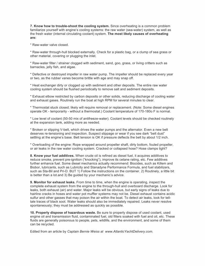
7. Know how to trouble-shoot the cooling system. Since overheating is a common problem familiarize yourself with engine’s cooling systems: the raw water (sea-water) system, as well as the fresh water (internal circulating coolant) system. The most likely causes of overheating are:
* Raw-water valve closed.
* Raw-water through-hull blocked externally. Check for a plastic bag, or a clump of sea grass or other material, covering or plugging the inlet.
* Raw-water filter / strainer clogged with sediment, sand, goo, grass, or living critters such as barnacles, jelly fish, and algae.
* Defective or destroyed impeller in raw water pump. The impeller should be replaced every year or two, as the rubber vanes become brittle with age and may snap off.
* Heat exchanger dirty or clogged up with sediment and other deposits. The entire raw water cooling system should be flushed periodically to remove salt and sediment deposits.
* Exhaust elbow restricted by carbon deposits or other solids, reducing discharge of cooling water and exhaust gases. Routinely run the boat at high RPM for several minutes to clear.
* Thermostat stuck closed; likely will require removal or replacement. (Note: Some diesel engines operate OK - temporarily - without a thermostat.) Coolant temperature of 170-180o F is normal.
* Low level of coolant (50-50 mix of antifreeze-water). Coolant levels should be checked routinely at the expansion tank, adding more as needed.
* Broken or slipping V-belt, which drives the water pumps and the alternator. Even a new belt deserves re-tensioning and inspection. Suspect slippage or wear if you see dark “belt dust” settling at the engine’s base. Belt tension is OK if pressure deflects the belt by about 1/2 inch.
* Overloading of the engine: Rope wrapped around propeller shaft, dirty bottom, fouled propeller, or air leaks in the raw water cooling system. Cracked or collapsed hose? Hose clamps tight?
8. Know your fuel additives. When crude oil is refined as diesel fuel, it acquires additives to reduce smoke, prevent pre-ignition (“knocking”), improve its cetane rating, etc. Few additives further enhance fuel. Some diesel mechanics actually recommend: Biocides, such as Killem and Biobor, lubricants, such as Lubricity and Stanadyne Performance Formula, and fuel stabilizers, such as Sta-Bil and Pri-D. BUT 1) Follow the instructions on the container. 2) Routinely, a little bit is better than a lot.and 3) Be guided by your mechanic’s advice.
9. Monitor for exhaust leaks. From time to time, when the engine is operating, inspect the complete exhaust system from the engine to the through-hull and overboard discharge. Look for leaks, both exhaust (air) and water. Major leaks will be obvious, but early signs of leaks due to hairline cracks in hoses and water pot muffler systems may not be. Diesel exhaust contains acidic sulfur and other gasses that may poison the air within the boat. To detect air leaks, look for tell-tale traces of black soot. Water leaks should also be immediately repaired. Leaks never resolve spontaneously; they must be addressed as quickly as possible.
10. Properly dispose of hazardous waste. Be sure to properly dispose of used coolant, used engine oil and transmission fluid, contaminated fuel, old filters soaked with fuel and oil, etc. These fluids are generally poisonous to people, pets, wildlife, and the environment, and some of them can be recycled.
Edited from an article by Captain Bernie Weiss at www.AtlanticYachtDelivery.com.

3.0
PROPULSION SYSTEM PROPULSION SYSTEM 3.1 GENERAL Your 40z is propelled by twin Volvo diesel 370 HP D6 engines with 24 overhead valves, turning (via IPS transmission) forward facing duo-prop propellers. The dual-lever electronic control acts as a combination throttle and gear selector. Care should be taken when shifting. Always allow the transmission to engage the new gear before throttling up. If the two levers are set to within 200 RPM of one another, they will automatically synchronize. The engine should never be running when swimmers are near the boat.
Unscrew Cap when engine cold to check COOLANT LEVEL
OIL LEVEL DIPSTICK See Page 65 of Volvo IPS Operator’s Manual
for greater detail of engine components NEW ENGINE BREAK-IN While running the engine for the first time and after shut-down, check for proper engine oil pressure, diesel fuel leaks, engine oil leaks, coolant leaks, proper operation of the indicators and gauges, proper exhaust color, engine vibrations and sounds, If temperature is high (a) Is the raw water intake seacock open at the base of the IPS drives? (b) Are the raw water strainers clogged? The engine may seize if it is operated when seawater intake is restricted or if load is applied without allowing the water temperature (engine) to warm up. During the first 10 hours of operation, full load should only be applied for short periods. Never run the engine for a long period at a constant RPM during this period. Higher oil consumption is typical at this time, so carefully observe oil pressure and engine temperature, exhaust color and check engine oil and coolant levels frequently... i.e. daily.
CHAPTER 3
FUEL FILTER w/bleeding pump & nipple
RAW WATER INTAKE STRAINERS

Volvo Penta’s 6-cylinder D6-370 is developed from the latest de-sign in modern diesel technology. The engine has common rail fuel injection system, double overhead camshafts, 4 valves per cylinder, turbocharger and aftercooler. To-gether with a large swept volume and the EVC system (Electronic Vessel Control), this results in world-class diesel performance, combined with low emissions. D6-370 with HS80AE reverse gear
VOLVO PENTA INBOARD DIESEL
D6-370272 kW (370 hp) crankshaft power acc. to ISO 8665
Diesel performancefor marine use
World-class performanceThe common rail fuel injection system, con-trolled by EVC, in combination with a large swept volume, ensures outstanding torque during the acceleration, with virtually no sign of smoke. This matched with the en-gine’s high load carrying capability creates a sporty feeling and power, when needed.
Compact and robustThe engine is lightweight and extremely compact for its large swept volume and high output. With the rear-end transmis-sion, driving the high-pressure injection pump and the camshafts, a high degree of integrated systems, a high-effi ciency after-cooler, a marinization performed with very few hoses, and a fully symmetric engine, the package simply gets that compact. The rigid cast-iron cylinder block and head, ladder frame, and exactly controlled (up to three steps) fuel injection gives excellent onboard comfort with low noise and vibration levels.
EVC/EC – Plug and goEVC Electronic Vessel Control is the latest development in engine control and instru-mentation for Volvo Penta marine engines. It offers a higher level of integration in your boat: electronic shift and throttle for smooth and safe control, a complete range of easy to read data link gauges, an EVC System Display (option) and much more, everything in just one CAN cable. EVC makes boating easier and safer with twin engine synchronization and new software functions such as Volvo Penta Low Speed (option), which signifi cantly reduces
boat speed at idle to simplify maneuvering in tight quarters. EVC is scalable from one station up to four, from a classic dashboard up to an advanced driver information system. EVC works closely together with the engine management system offering you constant power output regardless of temperature (5–55°C / 41–131°F) and qual-ity of the fuel. The system is built on the latest automotive technology with waterproof con-nectors, so it’s just plug and go.
A propulsion package fully matched, tested and supported by one companyVolvo Penta’s hydraulically shifted re verse gear has been specially de vel oped with a view to in-creasing the stand ard of com fort on board. Matched with the characteristics of the D6 engine, the hy drau lic shifting mechanism and a gear tech nol o gy that uses bevel gears through out the gear train, we have developed a complete package for high torque, operational reliability and reduction of engine noise and vibrations. The combination of 8° down angle, large drop center and small di men sions pro vides for opti-mized installations. V-drives are also available. In order to get full benefi t of the EVC sys tem the reverse gear is equipped with elec tric shift-ing valve.
Meeting new emission standardsThe common rail injection system in combination with electronics and an advanced combustion system are setting new standards in minimizing noxious emissions and particulates. The engine complies with the comprehensive emission require-ments introduced in Europe and the US in 2006.
0
10
20
30
40
50
60
70
Fuel consumptionAt calculated propeller load exp. 2.5
1600 1800 2000 2200 2400 2600 2800 3000 3200 34000
10
20
30
40
50
60
70
0
5
10
15
Liters/h US gal/h
Rpm
0
25
50
75
100
125
150
175
200
225
250
275
Power
1600 1800 2000 2200 2400 2600 2800 3000 3200 34000
25
50
75
100
125
150
175
200
225
250
275
0
50
100
150
200
250
300
350
kW hp, metricCrankshaft power
Calculated propeller load exp. 2.5
Rpm
440
490
540
590
640
690
740
790
840
890
TorqueTorque measured at crankshaft
1600 1800 2000 2200 2400 2600 2800 3000 3200 3400
440
490
540
590
640
690
740
790
840
890
40
45
50
55
60
65
70
75
80
85
90Nm kpm
Rpm

D6-370
Technical DataEngine designation . . . . . . . . . . . . . . . . . . . . . . . . D6-370 ICrankshaft power, kW (hp) . . . . . . . . . . . . . . . . . 272 (370)Propeller shaft power, kW (hp) . . . . . . . . . . . . . . 267 (363)Engine speed, rpm . . . . . . . . . . . . . . . . . . . . . . . . 3500Displacement, l (in3) . . . . . . . . . . . . . . . . . . . . . . . 5.5 (336)Number of cylinders . . . . . . . . . . . . . . . . . . . . . . . 6Bore/stroke, mm (in.) . . . . . . . . . . . . . . . . . . . . . . 103/110 (4.05/4.33)Compression ratio . . . . . . . . . . . . . . . . . . . . . . . . 17.5:1Dry weight with HS80AE, kg (lb) . . . . . . . . . . . . 677 (1493)Ratio HS80AE . . . . . . . . . . . . . . . . . . . . . . . . . . . 2.50:1, 1.96:1, 1.57:1Ratio HS80IVE . . . . . . . . . . . . . . . . . . . . . . . . . . . 2.49:1, 2.0:1, 1.64:1Duty rating: R5Technical data according to ISO 8665. With fuel having an LHV of 42,700 kJ/kg and density of 840 g/liter at 15°C (60°F). Mer-chant fuel may differ from this specifi cation which will in fl u ence engine power output and fuel consumption.The engine complies with the comprehensive emission requirements introduced in Europe and the US in 2006.
Dimensions D6-370/HS80AE Not for installation
Technical description:Engine block and head— Cylinder block and cylinder head made
of cast-iron— Ladder frame fi tted to engine block— 4-valve technology with hydraulic lash
adjusters— Double overhead camshafts— Oil-cooled pistons with two compres-
sion rings and one oil scraper ring— Integrated cylinder liners— Replaceable valve seats— Seven-bearing crankshaft— Rear-end transmission
Engine mounting— Flexible engine mounting
Lubrication system— Easily re place able separate full-fl ow and
by-pass oil fi lter— Seawater-cooled tubular oil cooler
Fuel system— Common rail fuel injection system— Control unit for processing the injection— Fine fi lter with water separator
Air inlet and exhaust system— Air fi lter with replaceable insert— Crankcase gases vented into the air inlet— Exhaust elbow or exhaust riser— Freshwater-cooled turbo charger
Cooling system— Thermostatically regulated freshwater cool-
ing— Tubular heat exchanger with separate large
volume expansion tank — Coolant system prepared for hot water out let— Easily accessible seawater impeller pump
Electrical system— 12V or 24V two-pole electrical system— 14V/115A or 28V/80A marine alternator
with Zener-di odes to protect the system from peak volt age, and integrated charging regu-lator with battery sensor cable for max i mum use of alternator
— Fuses with automatic reset (12V) and fuses with manual reset (24V)
— Auxiliary stop button
Instruments/control— Complete instrumentation including key
switch and interlocked alarm
— EVC monitoring panels for single or twin in stal la tions
— Electronic remote control for throttle and shift
— Plug-in connections
Reverse gear— Reverse gear with matched drop center and
8° down an gle for compact installation and min i mum pro pel ler shaft angle. V-drive avail- able.
— Bevel gears which results in smooth run- ning at all speeds
— Hydraulically operated clutch for smooth shift ing
— Electrical shifting performed by elec tro -mag net ic valves
— When under sail propeller shaft can ro tate 24 hours without engine start
— Seawater-cooled oilcooler— Low speed as option
AccessoriesAn extensive range of accessories are avail- able. For detailed information, please see the Ac ces so ries & Maintenance Parts catalog (www.volvopenta.com).
Contact your local Volvo Penta dealer for further in-formation.
Not all models, standard equipment and accessories are avail able in all countries. All specifi cations are sub-ject to change without notice.
The engine illustrated may not be entirely identical to pro duc tion standard engines.
09-2
006.
©
200
6 A
B V
olvo
Pen
ta.
AB Volvo PentaSE-405 08 Göteborg, Sweden
www.volvopenta.com

CHAPTER 3
3.2
Your engine passes seawater (raw water) through an intake in the IPS drive unit under the hull through a heat exchanger where it cools the engine’s coolant. This coolant is circulated through the engine and returns to the heat exchanger. For the engine to keep cool, it must have an adequate supply of raw water and coolant. Periodically check to be sure it’s clean and check the coolant level by opening the caps on top of the engine. Coolant should be close to the top of the reservoir on top of the front port corner of the engines.
Do not attempt to remove the coolant cap of a hot engine.
For details on what type of coolant to use, consult the engine operator’s manual or the maintenance schedule included in this manual. As the water and exhaust exit out the back of the drives, it is not as easy to check raw water flow. It is recommended to pay close attention to water temperature (167°-194° F is normal) at the outset.
3.3
Both the engine and transmission use oil for lubrication. The transmission will tend to use less oil than the engine, but both should be checked frequently. For the proper type of oils to use (which may depend on the service area and conditions) consult the engine manufacturer’s operator’s manual. The engine oil may be checked between the engines by pulling up the red dipsticks, at least ½ hour after running of the engines to allow the oil to drain down from the upper part of the engine. The transmission dipstick is red and unscrews. It is difficult to find and reach as one must get down between engines aft, move aft then reach behind the IPS drives to unscrew these caps. A small price to pay perhaps for the wonders of how well the IPS operates.
Be sure not to overfill this reservoir as damage to the engine could result. 3.4
Read page 79 and pages 89-91 of the Volvo Operators Manual (VOM) carefully. In addition to transom zincs, there are two engine zincs plus an iron anode in the exhaust cavity of the drive and care must be taken of the drive housing and coating of the propulsion unit. The props and propulsion unit have “PropSpeed” applied when delivered. Be sure to inspect and recoat if there are any scratches or whenever the boat is hauled. The timing for replacing zincs varies depending on the characteristics of the seawater, the amount of electrical current in marinas, or could indicate (if excessive wear is noted) an electrical short on the boat, etc. Inspect the engine zinc periodically at the time of oil changes and remove the corroded area on the surface, replacing them when deteriorated to less than 50% of original size. Otherwise corrosion-cooling system will occur and water leakage or parts breakage will result. Be sure to close the raw water intakes at the base of drives, before removing a plug to replace a zinc.
- 13 -
COOLING
LUBRICATION (IPS 500 Drive Shown)
CORROSION PROTECTION
PROPULSION SYSTEM
Transmission Dipstick (Hidden aft of IPS Drives)
RAW WATER INTAKE VALVE Shown OPEN

CHAPTER 3
3.5
Diesel engines use a large quantity of air for combustion. The engine of the 40z gets this air thru grills under the cockpit coaming, both port and starboard. Be sure that these aren’t blocked with gear on deck when underway.
3.6
The EVC Control Panel allows the operator to perform settings and choose information displayed on the engine LCD Display screen below. See Volvo Operator’s Manual for settings and options.
PROPULSION SYSTEM
ENGINE AIR INTAKES
ENGINE CONTROL/DISPLAY PANEL

PROPULSION SYSTEM
3.7 ENGINE CONTROL LEVERS
There 5 positions (front to back). FORWARD IDLE FORWARD
NEUTRAL IDLE REVERSE
REVERSE
The port and starboard engine RPMs will synchronize automatically when within 200 RPM of each other. Emergency Shifting If a fault occurs which prevents electronic gear shifting with the control levers; it is possible to shift manually using the procedure outlined on page 56-57 of the VPOM.
SUDDEN MOVEMENT HAZARD This control lever governs both throttle and shifting functions. The boat may start to move abruptly when the marine gear is engaged: Ensure the boat is clear of all obstacles forward and aft. Cautiously shift to the IDLE FORWARD position then quickly back to NEUTRAL position. Observe whether the boat moves as you expect. Before starting the engine, make sure (1) the raw water intake seacock over the IPS drive flange is in the OPEN position (2) the raw water strainer is clean (3) the engine has sufficient oil and coolant (4) transmission fluid is at the proper level (5) there are no restrictions to the air intake grills (6) the fuel valves over the tanks are OPEN (8) the HOUSE and BOTH ENGINE battery banks are turned ON (9) the throttle is in the neutral position (9) no one is in the water near the boat and (10) all machinery space hatches are closed.
3.8 STARTING
TURN ON ENGINES Push IGNITION button then wait until the Engine data appears on the control screen. A long continuous beep indicates that the self-test function has failed. START ENGINES by pushing the START/STOP button. Note: If you can’t hear the engines (These are quiet boats), look at the RPM on the display to see that it climbs to 600-700. The engine will not start unless the shift levers are in NEUTRAL.
Never engage the starter motor while the engine is running. This may damage the pinion and/or ring gear.
IF BATTERY VOLTAGE is low and you have difficulty turning over the
engine, a momentary. Parallel Switch is located next to two Engine Start Battery Switches on the electrical panel belowdecks. By pushing this switch on, you add the capacity of the house bank to the start battery. Once started, turn OFF the Parallel Switch. It is for emergency use only. TO REV THE ENGINES out of gear. See Volvo Penta Owner Manual.
PROPULSION SYSTEM
3.9 ALARM DISPLAY When the ignition key is first turned ON to position I, you may hear an audible alarm signal and see a “Stop Sign” appear on the Display, indicating that the diagnostic function has registered a malfunction. Please refer to Volvo Operator’s Manual chapters for detailed information about FAULTS and recommended action starting on page 40 of the VPOM.
3.10 STOPPING
Put both engine controls in NEUTRAL. Turn & hold the spring-loaded Ignition Key with pressure to the left until the engine stops. If unsuccessful, there’s a clearly labeled “Emergency Shutdown” button in the upper middle poside of the engine. Make sure to turn OFF Engine Battery Switches on the electrical panel when leaving the boat. Engine Stop & Restart after Crash-Stop If the engine otherwise stops, the following procedure for re-start must be followed. 1. Put control lever in NEUTRAL
2. Acknowledge any ALARM
3. TURN & HOLD ignition switch left to OFF until all lamps have gone out.
4. Then TURN the ignition system to the ON (not the engine Start) position only.
5. Acknowledge any ALARM
6. START the engine by: TURNING & HOLDING the ignition switch to the right.
7. STOP the engine. Wait again until all lamps have gone out.
8. RESTART the Engine.
3.11 OPERATING PARAMETERS
While it’s good to run the engine at top speed periodically for a minute or so, “Max Cruising Speed” is at least 10% below full throttle of 3500 rpm, or 3150 rpm.. While running, pay attention to the engine gauges on the LCD display. A significant change in oil or coolant temperature, oil pressure, or voltage should investigated immediately before the engine is damaged. OIL PRESSURE – Normally between 4.5 and 5 bars, except lower when idling COOLANT TEMPERATURE – Normally between 167 and 194 degrees F. CHARGING – Normally about 14 Volts when underway. Depending on hull structure and engine installation, engine and hull resonance may be greater at some speeds than others. This is normal and you will learn to pick the sweet spots. If you hear any abnormal sounds, stop the engine and inspect.
If any warning lights or buzzers activate, stop the engine immediately. Determine the cause and repair the problem before continuing to operate.
CHAPTER 3
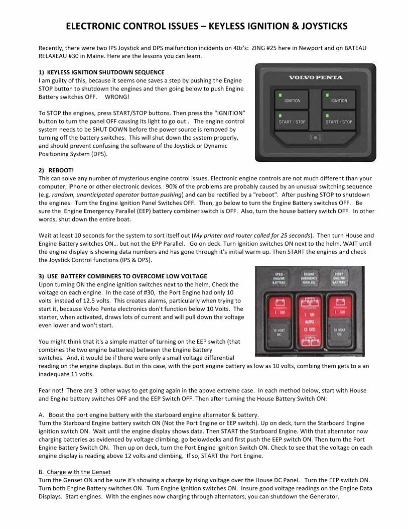
ELECTRONIC)CONTROL)ISSUES)–)KEYLESS)IGNITION)&)JOYSTICKS!!Recently,!there!were!two!IPS!Joystick!and!DPS!malfunction!incidents!on!40z's:!!ZING!#25!here!in!Newport!and!on!BATEAU!RELAXEAU!#30!in!Maine.!Here!are!the!lessons!you!can!learn.!!1)))KEYLESS)IGNITION)SHUTDOWN)SEQUENCE!I!am!guilty!of!this,!because!it!seems!one!saves!a!step!by!pushing!the!Engine!STOP!button!to!shutdown!the!engines!and!then!going!below!to!push!Engine!Battery!switches!OFF.!!!!!WRONG!!!!!To!STOP!the!engines,!press!START/STOP!buttons.!Then!press!the!“IGNITION”!button!to!turn!the!panel!OFF!causing!its!light!to!go!out!.!!!The!engine!control!system!needs!to!be!SHUT!DOWN!before!the!power!source!is!removed!by!turning!off!the!battery!switches.!!This!will!shut!down!the!system!properly,!and!should!prevent!confusing!the!software!of!the!Joystick!or!Dynamic!Positioning!System!(DPS).!!!!2))))REBOOT!!!!!This!can!solve!any!number!of!mysterious!engine!control!issues.!Electronic!engine!controls!are!not!much!different!than!your!computer,!iPhone!or!other!electronic!devices.!!90%!of!the!problems!are!probably!caused!by!an!unusual!switching!sequence!(e.g.!random,(unanticipated(operator(button(pushing)!and!can!be!rectified!by!a!"reboot".!!After!pushing!STOP!to!shutdown!the!engines:!!Turn!the!Engine!Ignition!Panel!Switches!OFF.!!Then,!go!below!to!turn!the!Engine!Battery!switches!OFF.!!!Be!sure!the!!Engine!Emergency!Parallel!(EEP)!battery!combiner!switch!is!OFF.!!Also,!turn!the!house!battery!switch!OFF.!!In!other!words,!shut!down!the!entire!boat.!!Wait!at!least!10!seconds!for!the!system!to!sort!itself!out!(My(printer(and(router(called(for(25(seconds).!!Then!turn!House!and!Engine!Battery!switches!ON…!but!not!the!EPP!Parallel.!!!Go!on!deck.!Turn!Ignition!switches!ON!next!to!the!helm.!WAIT!until!the!engine!display!is!showing!data!numbers!and!has!gone!through!it's!initial!warm!up.!Then!START!the!engines!and!check!the!Joystick!Control!functions!(IPS!&!DPS).!!3)))USE))BATTERY)COMBINERS)TO)OVERCOME)LOW)VOLTAGE!Upon!turning!ON!the!engine!ignition!switches!next!to!the!helm.!Check!the!voltage!on!each!engine.!!In!the!case!of!#30,!!the!Port!Engine!had!only!10!volts!!instead!of!12.5!volts.!!This!creates!alarms,!particularly!when!trying!to!start!it,!because!Volvo!Penta!electronics!don't!function!below!10!Volts.!!The!starter,!when!activated,!draws!lots!of!current!and!will!pull!down!the!voltage!even!lower!and!won't!start.!!You!might!think!that!it's!a!simple!matter!of!turning!on!the!EEP!switch!(that!combines!the!two!engine!batteries)!between!the!Engine!Battery!switches.!!And,!it!would!be!if!there!were!only!a!small!voltage!differential!reading!on!the!engine!displays.!But!in!this!case,!with!the!port!engine!battery!as!low!as!10!volts,!combing!them!gets!to!a!an!inadequate!11!volts.!!!!Fear!not!!!There!are!3!!other!ways!to!get!going!again!in!the!above!extreme!case.!!In!each!method!below,!start!with!House!and!Engine!battery!switches!OFF!and!the!EEP!Switch!OFF.!Then!after!turning!the!House!Battery!Switch!ON:!!A.!!!Boost!the!port!engine!battery!with!the!starboard!engine!alternator!&!battery.!!!!Turn!the!Starboard!Engine!battery!switch!ON!(Not!the!Port!Engine!or!EEP!switch).!Up!on!deck,!turn!the!Starboard!Engine!ignition!switch!ON.!!Wait!until!the!engine!display!shows!data.!Then!START!the!Starboard!Engine.!With!that!alternator!now!charging!batteries!as!evidenced!by!voltage!climbing,!go!belowdecks!and!first!push!the!EEP!switch!ON.!Then!turn!the!Port!Engine!Battery!Switch!ON.!!Then!up!on!deck,!turn!the!Port!Engine!Ignition!Switch!ON.!Check!to!see!that!the!voltage!on!each!engine!display!is!reading!above!12!volts!and!climbing.!!If!so,!START!the!Port!Engine.!!!!B.!!Charge!with!the!Genset!Turn!the!Genset!ON!and!be!sure!it's!showing!a!charge!by!rising!voltage!over!the!House!DC!Panel.!!!Turn!the!EEP!switch!ON.!Turn!both!Engine!Battery!switches!ON.!!Turn!Engine!Ignition!switches!ON.!!Insure!good!voltage!readings!on!the!Engine!Data!Displays.!!Start!engines.!!With!the!engines!now!charging!through!alternators,!you!can!shutdown!the!Generator.!!!!!!

C.!!Combine!the!House!Battery!with!the!Port!Engine!Battery!On!recent!boats!(see!below)!use!the!yellow!rotating!knob!with!a!push!button!center!labelled!"Port!Engine!Remote!(PER)!Switch"!on!top!of!a!small!black!box.!On!the!40z!for!example!it!is!located!on!the!starboard!bulkhead!inside!the!systems!compartment!under!the!pilothouse!hatch.!!See!below.!!
!!Starting!with!all!ignition!and!battery!switches!OFF!again.!Turn!the!House!Battery!and!Engine!Battery!switches!ON!(not!the!EEP!switch).!Then!go!into!the!central!pilothouse!hatch!and!push!the!yellow!button!on!top!of!!the!PER!switch!down!until!it!clicks!in!place.!Proceed!with!turning!the!Engine!Ignition!switches!ON.!Check!for!equal,!good!voltage!on!the!Engine!Displays.!!START!the!engines.!!WARNING:!!!The!above!procedures!may!get!you!going!for!a!short!run,!but!don't!be!complacent!about!it.!Too!much!on!the!boat!depends!on!both!batteries!functioning!properly.!!Lower!voltage!in!one!engine!start!battery!than!the!other!indicates!a!problem!with!the!charging!system!or!a!bad!battery.!!Monitor!closely!and!rectify!immediately!if!the!problem!persists.!!!!!!

4.1
4.2
STEERING CONTROL SYSTEM STEERING SYSTEM
The 40z has an integrated, electronically controlled power steering system which through electric motors rotate the two IPS pod drives below the hull. When running, the 40z is steered as with outboards or sterndrives. Thrust of the propellers is directed more immediately and precisely from side to side through a 26° arc to steer the boat.... rather than bouncing the prop wash from a conventional straight shaft propulsion unit off a rudder. When the throttle/shift levers are put in (N) neutral and a button pushed to activate the IPS joystick: Control of the pod drives is transferred from the throttle/shift levers to the IPS computer controlled joystick. When the joystick is activated, the steering wheel locks and no longer functions. Do not try to force it or damage may occur. Emergency Alignment If a fault occurs which prevents one or both of the propulsion units from being operated with the steering wheel, it is possible to align the faulty propulsion unit(s) so that its aimed straight ahead (and won’t act like a rudder), so as not to impair operation of either the remaining propulsion unit or the steering of the boat with the two engines. See pages 58-60 of the VPOM. Emergency Steering These controls are attached to the engine with cables, so if the electronic steering ever failed on both propulsion units, a steering method using the two engines can be employed. This is outlined on pages 60-61 of the VPOM.
IPS JOYSTICK DOCKING CONTROL
This control is used only for docking and maneuvering at slow speed. Learn to handle the joystick in a safe and correct manner before you start using the function in tight quarters. When the joystick is active, the normal engine controls are Neutral and inactive. A computer operates the drives and shifting. Rotation of the wheel is frozen and it should not be turned, as damage may occur.
To Activate: Both engines must be running and the engine control handles must be IN NEUTRAL. Press “DOCKING” button. A beep confirms it is active. To Deactivate : Either move the engine controls OUT OF NEUTRAL (forward or reverse) or press “DOCKING” button again. A double beep will confirm that it is OFF. Boost Function In windy weather or current when you need more oomph, push the right “HIGH” button after having frst activated the “Docking” button. A beep will confirm it’s engaged. Deactivate by pushing the button again. You’ll hear a double-beep confirmation. DPS - “DYNAMIC POSITIONING SYSTEM” OPTION. If the boat is equipped with this option to hold the boat on it’s heading and GPS position, it is activated by pushing the upper left button and deactivated by pushing it again, or simply engaging the engine controls. Maneuvering with Joystick Follow the arrows. Lean the joystick post in the direction you’d like to go. Release and the thrust stops. The boat may keep moving, so you may have to tap it in the opposite direction to stop it. The top of the joystick is rotated to orient the bow and stern, or to
- 18 -
CHAPTER 4

4.3
E165 GPS Plotter/Radar
E95 Display
IPS Joystick
Switch Panel ‘Trim Tabs
Genset Panel
STEERING CONTROL SYSTEM spin the boat completely around on its own axis. Pretty simple Takes some practice until it becomes completely intuitive. Joystick Calibration When moving the boat sideways if it seems that the bow or stern moves more than the other see page 109 of the Volvo Penta Operator’s Manual to make adjustments. HELM STATION NOTE: Panel Layout may vary between boats.
The helm station console is where most of the operational controls of the boat are located. Become familiar with these before you need to use them. In addition, make sure that when you are using the boat, even if you are not using a specific piece of equipment, that the circuit breakers are on for any equipment you might need.
i70 Multi/Depth
Anchor Counter
Volvo Control Panel
Throttle/Shift Levers
Engine Start/Stop Windlass Up/Down
FireBoy System Bilge Water Alarm 4”
- 19
CHAPTER 4
P70R Autopilot
Bilge Pumps (3)
4.4
4.5
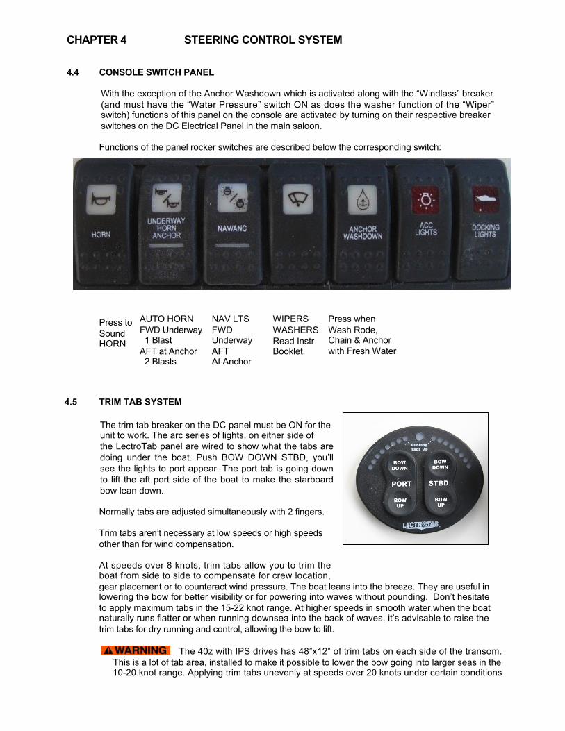
STEERING CONTROL SYSTEM CONSOLE SWITCH PANEL
With the exception of the Anchor Washdown which is activated along with the “Windlass” breaker (and must have the “Water Pressure” switch ON as does the washer function of the “Wiper” switch) functions of this panel on the console are activated by turning on their respective breaker switches on the DC Electrical Panel in the main saloon. Functions of the panel rocker switches are described below the corresponding switch:
Press to Sound HORN
TRIM TAB SYSTEM The trim tab breaker on the DC panel must be ON for the unit to work. The arc series of lights, on either side of the LectroTab panel are wired to show what the tabs are doing under the boat. Push BOW DOWN STBD, you’ll see the lights to port appear. The port tab is going down to lift the aft port side of the boat to make the starboard bow lean down. Normally tabs are adjusted simultaneously with 2 fingers. Trim tabs aren’t necessary at low speeds or high speeds other than for wind compensation. At speeds over 8 knots, trim tabs allow you to trim the boat from side to side to compensate for crew location, gear placement or to counteract wind pressure. The boat leans into the breeze. They are useful in lowering the bow for better visibility or for powering into waves without pounding. Don’t hesitate to apply maximum tabs in the 15-22 knot range. At higher speeds in smooth water,when the boat naturally runs flatter or when running downsea into the back of waves, it’s advisable to raise the trim tabs for dry running and control, allowing the bow to lift.
The 40z with IPS drives has 48”x12” of trim tabs on each side of the transom. This is a lot of tab area, installed to make it possible to lower the bow going into larger seas in the 10-20 knot range. Applying trim tabs unevenly at speeds over 20 knots under certain conditions
- 20 -
CHAPTER 4
AUTO HORN FWD Underway 1 Blast AFT at Anchor 2 Blasts
NAV LTS FWD Underway AFT At Anchor
WIPERS
Press when Wash Rode, Chain & Anchor with Fresh Water
WASHERS Read Instr Booklet.

4.6 4.7
STEERING CONTROL SYSTEM could cause the boat to attempt to roll over, particularly in a turn, due to the angle of IPS drives under the hull. Caution is advised. AUTOPILOT p70r The Navigtion Electronics breaker on the DC panel must be ON for the autopilot to function. Check the autopilot display and note the rudder angle indicator which helps in maneuvering the boat. When the compass heading is displayed on the autopilot it is operational and can be activated by pushing AUTO. The boat will then maintain the displayed heading. Turn the knob for incremental course changes. The Autopilot has been calibrated specifically for 40z operation. If you notice “hunting” rather than steady course keeping, see the Raymarine Manual to check Configuration parameters applied to your device or Contact Erik Rochelle at Boston BoatWorks
4.7 WINDSHIELD OPERATION While the triple windshield design creates individual windows that are smaller than those on the 34z, some owners have found that a stick with a rubber can tip is a handy way to push the windows out and assist in lowering them, without having to stretch over the console. We have investigated various electric options but have been unable to find any system that wasn’t ungainly, unsightly, tight, or unable to fully raise the windows for the open “flybridge” effect for good ventilation or perfect visibility at night or in fog. To travel at 14-15 knots without being blasted by the wind. Simply move slightly toward the centerline of the boat rather than directly behind the wheel to get out of the wind flow.
WINDSHIELD WIPERS The 40z is fitted with three windshield wipers. To activate the function, turn ON the breaker labeled “Wipers” on the DC Panel and also be sure that the “Fresh Water Pump” breaker is ON for the washer function to operate. To operate all 3 wipers at once, momentarily push the rocker switch slightly forward to the first detente. To operate just the starboard wiper, push the rocker switch, all the way forward. To change the wiper speed: While either all 3 or just the starboard wiper is operating, quick push the rocker switch all the way forward. Each quick push changes the speed. To operate the wash function for either all 3 wipers or just the starboard washer, PUSH and HOLD the rocker switch all the way forward until water jets appear.
- 21 -
CHAPTER 4
4.8
4.9
5.0
STEERING CONTROL SYSTEM
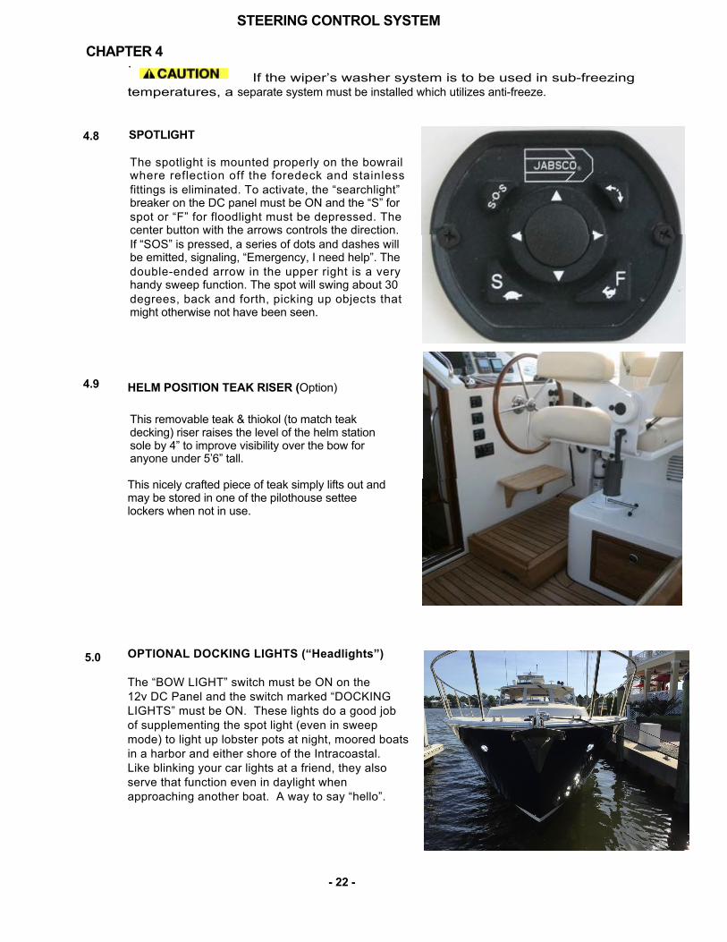
. If the wiper’s washer system is to be used in sub-freezing temperatures, a separate system must be installed which utilizes anti-freeze. SPOTLIGHT
The spotlight is mounted properly on the bowrail where reflection off the foredeck and stainless fittings is eliminated. To activate, the “searchlight” breaker on the DC panel must be ON and the “S” for spot or “F” for floodlight must be depressed. The center button with the arrows controls the direction. If “SOS” is pressed, a series of dots and dashes will be emitted, signaling, “Emergency, I need help”. The double-ended arrow in the upper right is a very handy sweep function. The spot will swing about 30 degrees, back and forth, picking up objects that might otherwise not have been seen.
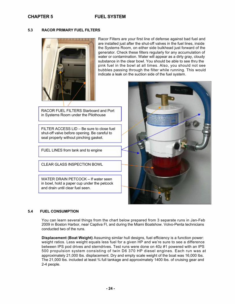
HELM POSITION TEAK RISER (Option)
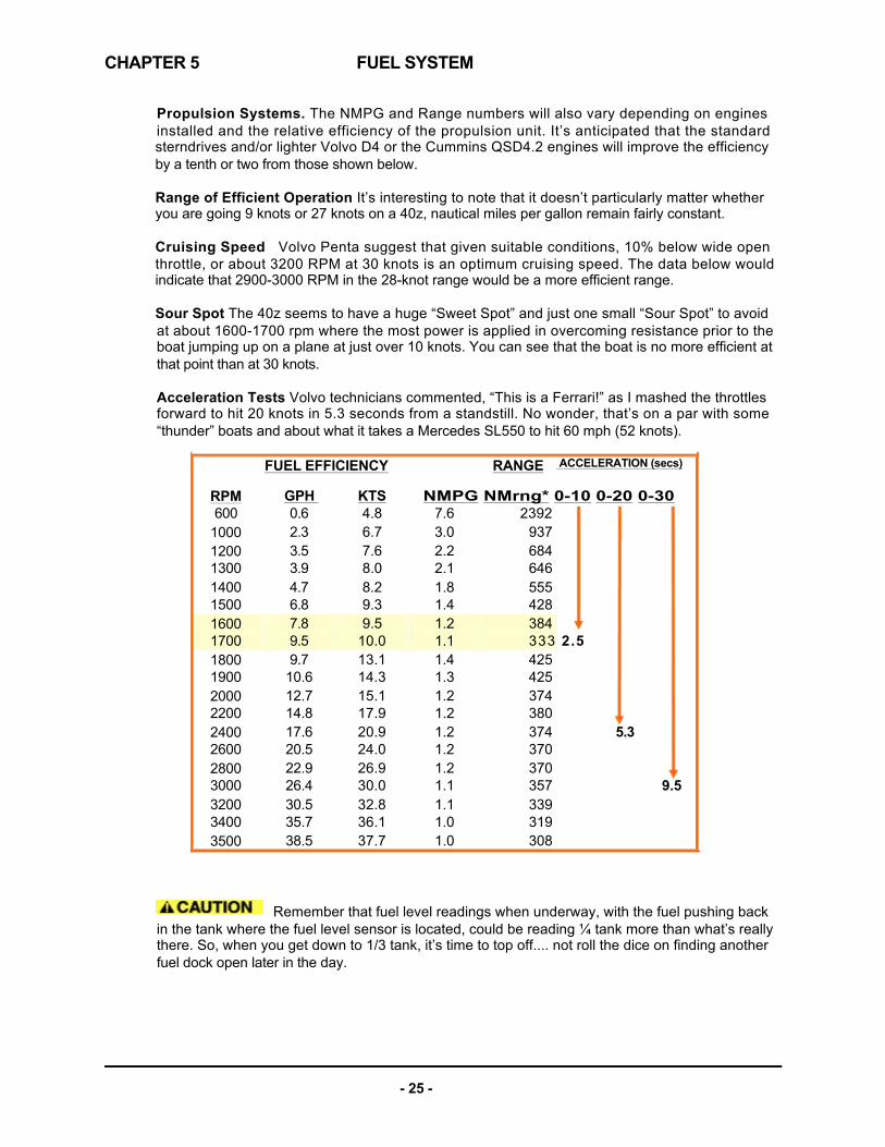
This removable teak & thiokol (to match teak decking) riser raises the level of the helm station sole by 4” to improve visibility over the bow for anyone under 5’6” tall. This nicely crafted piece of teak simply lifts out and may be stored in one of the pilothouse settee lockers when not in use. OPTIONAL DOCKING LIGHTS (“Headlights”) The “BOW LIGHT” switch must be ON on the 12v DC Panel and the switch marked “DOCKING LIGHTS” must be ON. These lights do a good job of supplementing the spot light (even in sweep mode) to light up lobster pots at night, moored boats in a harbor and either shore of the Intracoastal. Like blinking your car lights at a friend, they also serve that function even in daylight when approaching another boat. A way to say “hello”.
- 22 -
CHAPTER 4

5.0
5.1
5.2
FUEL SYSTEM GENERAL
It is important to understand the fuel system aboard your boat. Diesel fuel is different than gasoline. In most respects it is safer, however precautions need to be taken to maintain the safety of your boat. Please study the safety precautions in the NMMA publication “Sportfish, Cruisers, Yachts – Owner’s Manual.” Diesel engines need to intake more fuel than they burn, and so they differ from gasoline engines in that they return excess fuel to the tank. Both feed & return of port and starboard engines are to their respective 175-gallon fuel tanks. The two fuel tanks are connected at the bottom by a “compensating” fuel line with isolating shut-off valves at both aft inboard corners.
FUEL SHUT-OFF VALVES
These valves are located on top of the fuel tanks aft and are accessed through pilothouse seat lockers. In the photos below they are shown in the open position, parallel with the fuel lines.
These valves should be shut down if inspecting a Racor filter, in an emergency or in case of a fire in the engine compartment.
STARBOARD TANK showing fuel shut-off and top of fuel level sensor (right center)
FILLING THE TANKS Deck fills are mounted on the side decks, port & starboard, and are labeled “DIESEL.” Each one services only its respective tank, although with the connecting fuel line valve open, you will get some transfer to the opposite tank. As the tank is filled, vapor escapes the tank thru the vent. Overflow is prevented by an in-line fuel/air separator that will not allow fuel to pass.
should be taken while filling. Check the fuel level gauges and listen for the rise in pitch at the deck fill, as fuel reaches the top. Shut off the nozzle immediately. Do not attempt to “top off” the tanks. Have an absorbent cloth handy to prevent any overboard spillage. Variations in temperature as well as trim angle could cause overflow or vent-line blockage.
- 23 -
CHAPTER 5
PORT TANK showing fuel shut-off for port engine and generator (center hose).
CHAPTER 5
5.3
Racor Filters are your first line of defense against bad fuel and are installed just after the shut-off valves in the fuel lines, inside the Systems Room, on either side bulkhead just forward of the generator. Check these filters regularly for any accumulation of water or contamination. Water will appear as a dirty gray, cloudy substance in the clear bowl. You should be able to see thru the pink fuel in the bowl at all times. Also, you should not see bubbles passing through the filter while running. This would indicate a leak on the suction side of the fuel system.
RACOR FUEL FILTERS Starboard and Port in Systems Room under the Pilothouse
FILTER ACCESS LID – Be sure to close fuel shut-off valve before opening. Be careful to seal properly without pinching gasket.
FUEL LINES from tank and to engine
CLEAR GLASS INSPECTION BOWL
WATER DRAIN PETCOCK – If water seen in bowl, hold a paper cup under the petcock and drain until clear fuel seen.
5.4 FUEL CONSUMPTION
You can learn several things from the chart below prepared from 3 separate runs in Jan-Feb 2009 in Boston Harbor, near Captiva Fl, and during the Miami Boatshow. Volvo-Penta technicians conducted two of the runs. Displacement (Boat Weight) Assuming similar hull designs, fuel efficiency is a function power: weight ratios. Less weight equals less fuel for a given HP and we’re sure to see a difference between IPS pod drives and sterndrives. Test runs were done on 40z #1 powered with an IPS 500 propulsion system consisting of twin D6 370 HP diesel engines. Each run was at approximately 21,000 lbs. displacement. Dry and empty scale weight of the boat was 16,000 lbs. The 21,000 lbs. included at least ¾ full tankage and approximately 1400 lbs. of cruising gear and 2-4 people.
- 24 -
RACOR PRIMARY FUEL FILTERS
FUEL SYSTEM
CHAPTER 5
Propulsion Systems. The NMPG and Range numbers will also vary depending on engines installed and the relative efficiency of the propulsion unit. It’s anticipated that the standard sterndrives and/or lighter Volvo D4 or the Cummins QSD4.2 engines will improve the efficiency by a tenth or two from those shown below. Range of Efficient Operation It’s interesting to note that it doesn’t particularly matter whether you are going 9 knots or 27 knots on a 40z, nautical miles per gallon remain fairly constant. Cruising Speed Volvo Penta suggest that given suitable conditions, 10% below wide open throttle, or about 3200 RPM at 30 knots is an optimum cruising speed. The data below would indicate that 2900-3000 RPM in the 28-knot range would be a more efficient range. Sour Spot The 40z seems to have a huge “Sweet Spot” and just one small “Sour Spot” to avoid at about 1600-1700 rpm where the most power is applied in overcoming resistance prior to the boat jumping up on a plane at just over 10 knots. You can see that the boat is no more efficient at that point than at 30 knots. Acceleration Tests Volvo technicians commented, “This is a Ferrari!” as I mashed the throttles forward to hit 20 knots in 5.3 seconds from a standstill. No wonder, that’s on a par with some “thunder” boats and about what it takes a Mercedes SL550 to hit 60 mph (52 knots).
FUEL EFFICIENCY
RPM 600
1000 1200 1300 1400 1500 1600 1700 1800 1900 2000 2200 2400 2600 2800 3000 3200 3400 3500
Remember that fuel level readings when underway, with the fuel pushing back in the tank where the fuel level sensor is located, could be reading ¼ tank more than what’s really there. So, when you get down to 1/3 tank, it’s time to top off.... not roll the dice on finding another fuel dock open later in the day.
- 25 -
GPH 0.6 2.3 3.5 3.9 4.7 6.8 7.8 9.5 9.7
10.6 12.7 14.8 17.6 20.5 22.9 26.4 30.5 35.7 38.5
FUEL SYSTEM
KTS 4.8 6.7 7.6 8.0 8.2 9.3 9.5
10.0 13.1 14.3 15.1 17.9 20.9 24.0 26.9 30.0 32.8 36.1 37.7
NMPG NMrng* 0-10 0-20 0-30 7.6 3.0 2.2 2.1 1.8 1.4 1.2 1.1 1.4 1.3 1.2 1.2 1.2 1.2 1.2 1.1 1.1 1.0 1.0
RANGE
2392 937 684 646 555 428 384 333 2.5 425 425 374 380 374 370 370 357 339 319 308
ACCELERATION (secs)
5.3
9.5

CHAPTER 5
FUEL SYSTEM
MJM FUEL CONSUMPTION LOG

6.0
6.1
ELECTRICAL SYSTEM GENERAL The 40z’s electrical system may be more advanced than what you are accustomed to. It combines DC and AC power in several ways. Most of the electrical components on your boat use DC power. 12 volt DC power is stored in two 8D House Batteries and two 31G Start Batteries, totaling 700 Ampere Hours of capacity. This battery capacity is replenished in 3 ways :(1) Alternator output from the engines when running (2) From 110V 60cyle AC shorepower through the Mastervolt Charger or (3) From the Northern Lights Generator which outputs 110V 60-cycle power to the charger. 120-volt AC power, typically found in homes, is supplied to the boat in 3 ways: (1) via 1 or 2 shore-power cords plugged into a shoreside receptacle (2) by an optional generator or (3) by inverting DC power from a battery into AC power through the Mastervolt Inverter. The AC components aboard your boat include the refrigerator/freezer, cooktop, microwave, some TV components, the air-conditioning, water heater, inverter, and receptacles (plug in AC equipment).
Both AC and DC electrical power sources are potentially dangerous. Do not attempt to work on any part of your boat’s electrical system if you are not a qualified marine electrician.
ELECTRICAL PANELS
There are two battery banks on your boat. The house bank consists of (2) 245Ah, absorbed-glass mat (D8 AGM) batteries. The engine bank consists of two 105Ah Group 31 AGM start batteries which are also used to run the windlass. Whenever a charging source is present (either from the battery charger or an engine-driven alternator) both banks are automatically charged. AGM batteries are essentially no-maintenance.
Do not attempt to open the batteries. Other than keeping them properly charged, stored, and clean (especially between the terminals), there is virtually nothing you need to do to them. The battery charger is factory set specifically for AGMs. If the engine is not running, the batteries can be charged via the battery charger, which is powered by AC electricity either from your generator or shore- power. It is important to read and understand the inverter/charger manual to be sure that the unit is functioning as you expect.
Never al low your DC system’s voltage to fall below 11.2 volts. Sensitive electronics may fail to function. For this reason, it is advisable when leaving the boat to turn off all loads, turn off their respective circuit breakers, and turn off the main DC battery switches and turn off the inverter. 24 Hour Circuits The only load that remains on when the battery switches are in the OFF position are the “24 Hour” circuits (shown at right) which by- pass the panel circuit breakers and are connected directly to the batteries.
- 27 -
CHAPTER 6
BILGE PUMP
BILGE PUMP
BILGE PUMP
HIGH WATER ALRM
STEREO MEM
DVD MEM
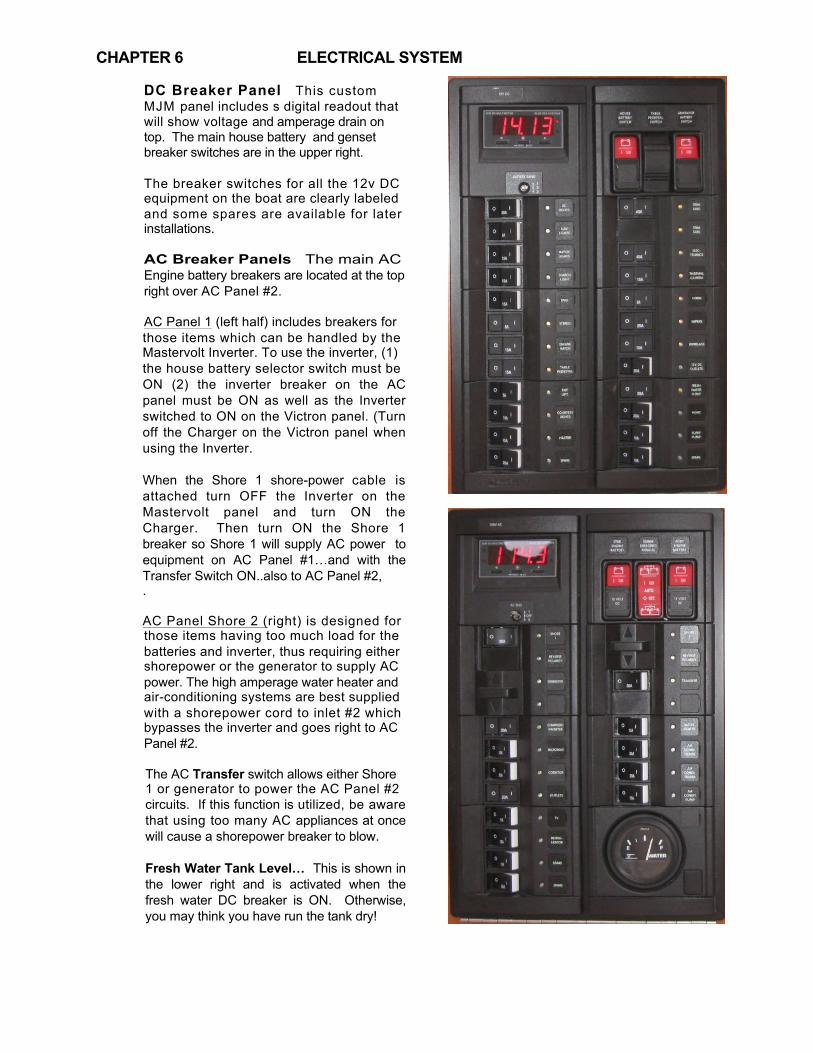
CHAPTER 6
DC Breaker Panel This custom MJM panel includes s digital readout that will show voltage and amperage drain on top. The main house battery and genset breaker switches are in the upper right. The breaker switches for all the 12v DC equipment on the boat are clearly labeled and some spares are available for later installations. AC Breaker Panels The main AC Engine battery breakers are located at the top right over AC Panel #2.
AC Panel 1 (left half) includes breakers for those items which can be handled by the Mastervolt Inverter. To use the inverter, (1) the house battery selector switch must be ON (2) the inverter breaker on the AC panel must be ON as well as the Inverter switched to ON on the Victron panel. (Turn off the Charger on the Victron panel when using the Inverter. When the Shore 1 shore-power cable is attached turn OFF the Inverter on the Mastervolt panel and turn ON the Charger. Then turn ON the Shore 1 breaker so Shore 1 will supply AC power to equipment on AC Panel #1…and with the Transfer Switch ON..also to AC Panel #2, . AC Panel Shore 2 (right) is designed for those items having too much load for the batteries and inverter, thus requiring either shorepower or the generator to supply AC power. The high amperage water heater and air-conditioning systems are best supplied with a shorepower cord to inlet #2 which bypasses the inverter and goes right to AC Panel #2. The AC Transfer switch allows either Shore 1 or generator to power the AC Panel #2 circuits. If this function is utilized, be aware that using too many AC appliances at once will cause a shorepower breaker to blow. Fresh Water Tank Level… This is shown in the lower right and is activated when the fresh water DC breaker is ON. Otherwise, you may think you have run the tank dry!
-
28 -
ELECTRICAL SYSTEM

CHAPTER 6 ELECTRICAL SYSTEM Charging The HOUSE battery switch can be switched OFF when the boat is not used, and the batteries will still accept a charge from 110V Shorepower through the battery charger. Leave “Inverter/Charger” breaker ON on AC Panel 1. Disconnecting shore power with INVERT left ON will cause discharge of the house battery bank.
6.2 AC SHOREPOWER The first of three ways to supply AC power to boat appliances/systems is through Shorepower #1 (plugged in) and #2 30A 125V connections in the transom. These are shown at right, along with a TV Cable hook-up socket. The cover lid springs back open by pushing sharply in at the bottom, If two 30A 125V sockets are not available on the dock, very often you will find a 50A 225V socket to which you can connect a “Y” pigtail (West Marine 410373). If you overload, an AC circuit, one of the two breakers may activate. To reset, locate the shorepower breaker box (shown at right) outboard under the port cockpit hatch cover and be sure both switches are in the UP position.
Hot Water Source If a second shore-power receptacle is not available and you have not operated the boat recently; there won’t be any hot water from the engine’s heat exchanger. Simply turn ON the Transfer switch of Shore 2, flick the hot water breaker on, wait 15 minutes and your shower will be ready. The above method can also be used to power the Air Conditioners, but beware that it will be more likely to overload the system if you are trying to use Air Conditioners and Hot Water
at the same time.
6.3 AC GENERATOR (Option) See Northern Lights M673L3 6 KW 60 Hz 1800 RPM
Generator Operating Manual. NOTICE! RUN YOUR GENSET You’ve heard that diesels like to be run. Don’t be concerned about engines that have been maintained and have good hours on them…worse are engines with too few hours. Your Genset is no exception. Having to deal with refurbished injectors, water-pump replacements, cooling-system rehabs and new hoses, etc. can be costly, if you don’t run It enough. Ideally, run it for at least 20 minutes with a good load (air conditioning systems and/or a Seakeeper are good examples) every time you take your boat out. The list of evils predicted for an underemployed genset is frightening. Salt-laden air can corrode the windings of the generator unit itself and sneak into the cylinders of the engine, bringing rust to cylinder walls and piston rings. Salt-laden moisture can build up in the oil, creating all kinds of acidic havoc. And fuel may turn to shellac or gum in or around the injectors. Lesson here is USE YOUR GENERATOR!
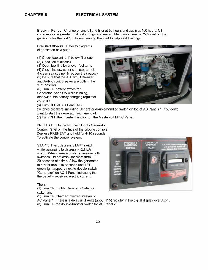
CHAPTER 6
Break-In Period Change engine oil and filter at 50 hours and again at 100 hours. Oil consumption is greater until piston rings are seated. Maintain at least a 75% load on the generator for the first 100 hours, varying the load to help seat the rings.
Pre-Start Checks Refer to diagrams of genset on next page. (1) Check coolant is 1” below filler cap (2) Check oil at dipstick (3) Open fuel line lever over fuel tank. (4) Close the raw water seacock, check & clean sea strainer & reopen the seacock (5) Be sure that the AC Circuit Breaker and AVR Circuit Breaker are both in the “Up” position (5) Turn ON battery switch for Generator. Keep ON while running, otherwise, the battery-charging regulator could die. (6) Turn OFF all AC Panel 1&2 switches/breakers, including Generator double-handled switch on top of AC Panels 1. You don’t want to start the generator with any load. (7) Turn OFF the Inverter Function on the Mastervolt MICC Panel. PREHEAT: On the Northern Lights Generator Control Panel on the face of the piloting console Depress PREHEAT and hold for 4-10 seconds To activate the control system.
START: Then, depress START switch while continuing to depress PREHEAT switch. When generator starts, release both switches. Do not crank for more than 20 seconds at a time. Allow the generator to run for about 15 seconds until LED green light appears next to double-switch “Generator” on AC 1 Panel indicating that the panel is receiving electric current. Then: (1) Turn ON double Generator Selector switch and (2) Turn ON Charger/Inverter Breaker on AC Panel 1. There is a delay until Volts (about 115) register in the digital display over AC-1. (3) Turn ON the double-transfer switch for AC Panel 2.
- 30 -
ELECTRICAL SYSTEM
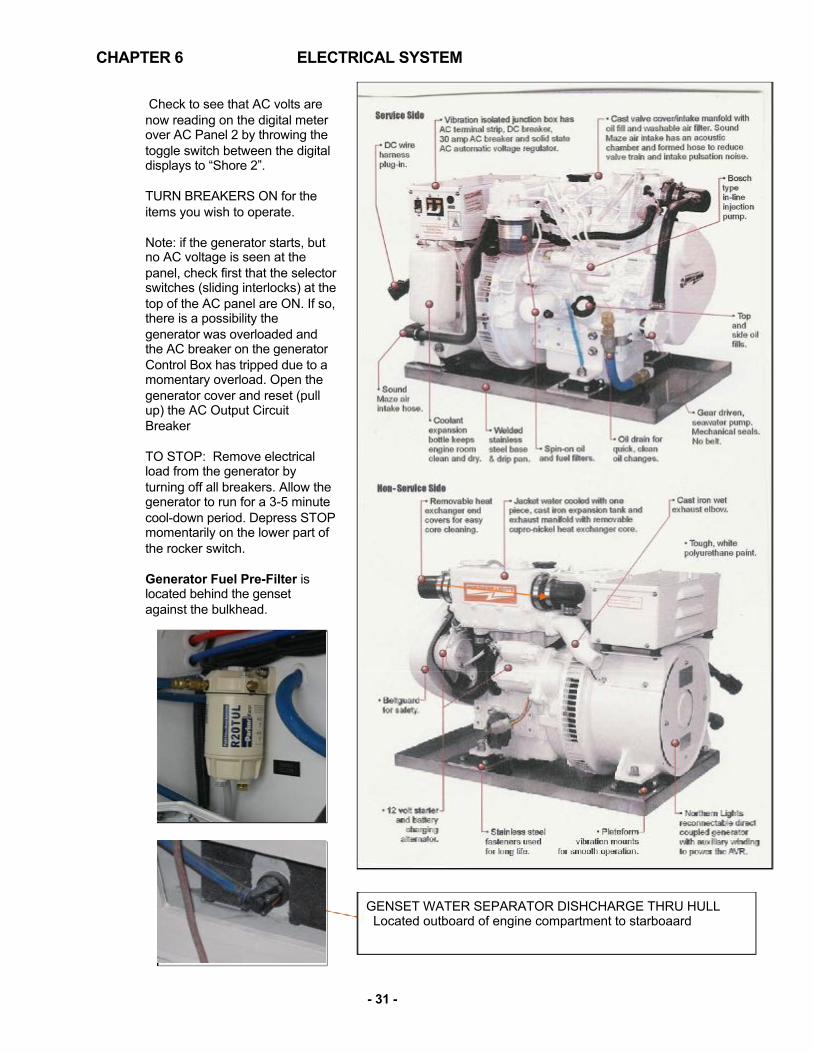
CHAPTER 6
Check to see that AC volts are now reading on the digital meter over AC Panel 2 by throwing the toggle switch between the digital displays to “Shore 2”. TURN BREAKERS ON for the items you wish to operate.
Note: if the generator starts, but no AC voltage is seen at the panel, check first that the selector switches (sliding interlocks) at the top of the AC panel are ON. If so, there is a possibility the generator was overloaded and the AC breaker on the generator Control Box has tripped due to a momentary overload. Open the generator cover and reset (pull up) the AC Output Circuit Breaker
TO STOP: Remove electrical load from the generator by turning off all breakers. Allow the generator to run for a 3-5 minute cool-down period. Depress STOP momentarily on the lower part of the rocker switch. Generator Fuel Pre-Filter is located behind the genset against the bulkhead.
GENSET WATER SEPARATOR DISHCHARGE THRU HULL Located outboard of engine compartment to starboaard
- 31 -
ELECTRICAL SYSTEM

6.4
ELECTRICAL SYSTEM VICTRON ENERGY AUTOMATIC INVERTER/CHARGER Under normal circumstances there is no need for adjustment or operation besides switching the toggle ON and OFF. The purpose of the inverter is to convert stored 12v DC energy in the extensive battery banks into 120v AC power to operate those accessories such as the microwave, hotplate, 120v outlets and TV, etc. that have breakers on the 120v Panel This Victron unit also takes AC power from the 30Amp Shorepower or the Generator to charge both house and engine start battery banks. The Inverter Control is shown at right. INVERTING To source AC power when no generator or shore-power is available: (1) Make sure the switch on top of the unit itself over the starboard fuel tank, under the pilothouse settee is ON. See diagram below. (2) Push the toggle switch on the Multi Control to “on” . AC power should now be supplied to the AC Panel 1, which includes those items which may be run from the inverter alone. The Air Conditioning and Water Heater Breakers can only be run either with the “Transfer” switch or directly from Shorepower 1 inlet or with the Generator. DO NOT LEAVE THE INVERT SWITCH “ON” either o the panel or on top of the unit itself IF YOU ARE NOT INVERTING AS THIS MAY DRAW 10-12 AMPS EVEN IF NO AC DEVICE IS TURNED ON. OR, YOU MAY END UP WITH DEAD BATTERIES (All of them if the Parallel Switch is ON too.) IN FACT, ALTHOUGH THIS UNIT CLAIMS TO HAVE AN AUTOMATIC SHUT OFF IF THE VOLTAGE GETS LOW TO PROTECT THE BATTERIES, IT’S BEST NOT TO OCUNT ON THAT IF YOU ARE GOING TO LEAVE THE BOAT ON A MOORING OR STORED ON LAND WITHOUT SHORE POWER. TURN OFF THE INVERTER ON THE TOP OF THE UNIT OVER THE FUEL TANK IN THE STARBOARD PILOTHOUSE SETTEE LOCKER.
- 32 -
CHAPTER 6

0710
6 - E
lect
rical
Loa
ds W
IP
AC
Loa
dsO
N/O
FFVo
ltage
Unit
Desc
riptio
nM
ake
Mod
elAm
ps/U
nit
Tota
l Wat
tsUs
age
(%)
Amp
Draw
Wat
tsIn
verta
ble
load
sN
o11
51
Mic
row
ave/
Con
vect
ion
Sha
rpR
-820
JS13
.00
1495
100%
0.0
0Ye
s11
53
Tele
visi
onLG
26LN
4500
0.33
114
66%
0.7
75Ye
s11
58
GFC
I out
lets
2.50
2300
15%
3.0
345
No
115
1C
offe
e M
aker
Ker
uig
Ker
uig
MIN
I Plu
s11
.88
1366
100%
0.0
0N
o11
51
Cen
tral V
acuu
mD
irt D
evil
Dirt
Dev
il C
V15
0011
.70
1346
100%
0.0
0N
o11
51
Coo
ktop
Ken
yon
Ken
yon
Lite
Tou
ch20
.00
2300
60%
0.0
0Ye
s11
51
Ref
riger
ator
- G
alle
yIs
othe
rmIs
othe
rm D
R 1
609.
2010
5825
%2.
326
5To
tal A
mp
Dra
w:
6.0
Tota
l (kW
):10
.0Us
age
(kW
):0.
7
Non
-Inve
rtabl
e lo
ads
Yes
115
1B
atte
ry C
harg
erV
ictro
nC
enta
ur C
harg
er 1
2/10
014
.40
1656
25%
1.8
414
Yes
115
2A
/C A
ir H
andl
ers*
Mar
ine
Air
VTD
16K
-HV
13.6
031
2865
%8.
820
33Ye
s11
51
A/C
Pum
p -
Sea
Wat
erM
arin
e A
irP
MA
1000
2.20
253
100%
1.1
253
No
115
1C
loth
s W
ashe
r/Dry
erTB
DTB
D0
100%
0.0
0Ye
s11
51
Gyr
o S
eaw
ater
Pum
p M
arin
e A
irP
MA
500
2.10
242
100%
1.1
242
Yes
115
1G
yro
Sta
biliz
erS
eake
eper
Sea
keep
er 5
17.3
920
0075
%6.
515
00Ye
s11
51
Wat
er H
eate
rIn
del
Isot
emp
Bas
ic 5
06.
5275
050
%1.
637
5To
tal A
mp
Dra
w:
20.9
Tota
l (kW
)6.
4To
tal (
kW):
4.8
*Fu
ll Lo
ad A
mps
HE
AT
(Coo
l is
10.4
Am
ps)
Zurn
Yac
ht D
esig
nP
rinte
d 9/
29/2
014

6.5 6.6 6.7
6.8
6.9
6.10
ELECTRICAL SYSTEM
CHARGING Push the toggle switch to “charge only” on the Multi Control Panel to activate the charger when SHORE POWER is connected or when the GENERATOR is on.
REVERSE POLARITY As a safety precaution, your AC panel is fitted with reverse polarity indicators. If an AC supply were wired incorrectly, either aboard your boat or shoreside, a dangerous shock situation could exist. Normally, the reverse polarity lights should not be illuminated. If they are, disconnect that source of power and alert the appropriate person.
ELECTROLYSIS & GALVANIC CORROSION Metallic fittings that are exposed to saltwater are subject to electrolysis and galvanic corrosion. To minimize potential damage, your boat is fitted with a sacrificial zinc at the transom. This zinc is connected to the bonding system of your boat. It should be visually inspected whenever possible and replaced when 1/2 of the zinc has been eroded. Pay special attention to its condition when in new waters and marinas, as environmental conditions affect the rate of deterioration. If the zinc erodes rapidly, current meters can be used to assess possible causes and remedies. See the Volvo Penta Operator’s Manual for sacrificial anode location and inspection on the engine as well as the drives. BONDING The bonding system of your boat connects all underwater metallic fittings to the sacrificial zinc and the boat’s negative bus bar. In order for the zinc to protect an underwater part, the connection must be clean and secure. The green wires that make up this system are not normally current carrying. ELECTRICAL SAFETY Please read and understand the important safety precautions included in the included NMMA publication “Sportfish, Cruisers, Yachts – Owner’s Manual” concerning electrical safety.
FUSE LOCATIONS & SPECIFICATION (SEE NEXT PAGE)
- 33
CHAPTER 6 CHAPTER 7

7.0 7.1
7.2
FRESHWATER SYSTEM GENERAL The 40z incorporates a pressurized freshwater system from either of two sources (1) a single 100-gallon tank under the main saloon sole that supplies a pump which maintains a constant pressure in the system, or (2) a dock hose inlet located to port in the cockpit as shown at right. When connected, dock water and pressure is used directly by all outlets in the boat... by passing the freshwater pump and water tank. A check valve keeps the dock water supply from backing up into the boat’s water tank and overflowing it. CAUTION When using the dock water supply, be sure to turn OFF the “fresh water pump” breaker on the 12V DC Panel, otherwise the ship’s water pump may win the battle of water pressure and emptying your water tank into the city system. CAUTION When leaving the boat with the dock water supply hooked up, be sure to turn OFF the dock water faucet. If there’s a failure of a fresh water fitting or the pressure regulator, the boat could fill up with water and sink... as there is no limit to the amount of water from the city source as there is with the boats own water tank. FILLING WATER TANK
A deck fill is provided on the starboard side deck near the helm station and is labeled WATER. As the tank is filled, air escapes thru the vent. This tank cannot be filled using the dock hose inlet. The Fresh Water Gauge is located at the bottom of the AC Electrical Panel. JOHNSON AQUA JET WPS 10.4 DUO 12V FRESH WATER PUMP The breaker is located on the 12v DC Panel. When a faucet is turned on or a device such as the head or wipers activated, the pumps run, pressure builds until 0 bar/ 9 psi. At this point, the integrated pressure automatically switch off the first pump. At .8 bar/4 psi the second pump is shut off in the same way. The pumps are equipped with positively checking outlet valves, which ensure that the pressure is maintained after the pumps shut off. When water is demanded (at the faucet, shower etc.) the pressure decreases. After a moderate drop in pressure, the inte-grated pressure switches automatically turns the pumps back on. If the pump s heard running continually, check that no faucet has been left open. The transom shower is a frequent culprit. If this is not the case, turn off the pump and check the tank is not emptied. The pump is protected from sediment by an in-line strainer mounted adjacent to the pump. The strainer should be checked periodically and cleaned if necessary.
7.
CHAPTER 7

!

7.3 7.4
FRESHWATER SYSTEM
INDEL ISOTEMP 13 GALLON HOT WATER TANK Water in the 13-gallon hot water tank is located in the port pilothouse settee locker. Water in the tank is heated in one of 2 ways (1) whenever the engine is operating or (2) when the engine is not running, by turning on the “Water Heater” breaker on the 110v AC Panel. It is part of the freshwater system and does not need to be filled separately. There is virtually no need for maintenance, but the connections at the tank should be visually inspected occasionally. The coolant lines from the engine to the tank have shut-off valves. These need to be OPEN in order for the engine to heat the water in the tank. For service, or in case or a ruptured line, these valves can be closed to stop this water loop. GENERAL ECOLOGY SEAGULL WATER PURIFIER
[See also Seagull owner’s manual] The galley is fitted with the best available water purifier in the world that probably produces better water than obtained in supermarket bottled water. It is used on 85 airlines.and by the military where the water supply is contaminated by chemical warfare agents. This purifier has a cartridge (in stainless pressure vessel under sink) that should be replaced annually or when either reduced water flow indicates that it has become plugged with sediment or the taste is odd.
It is best to clear the pressure water system of any winter anti-freeze before
running water through the cartridge. The filter is rated for 1000 gallons, which is approximately 15 water tanks’ worth. Replace it at least once per year. The Jabsco Sensor Max VSD5.0 freshwater pump is turned on at the DC breaker panel. It is combned with the Groco, 2 gallon PSC-1 which accumulates pressure to 100 psi so the pump doesn’t have to scyle repeatedly. If the pump s heard running continually, check that no faucet has been left open. If this is not the case, turn off the pump and check that the tank has not been emptied. The pump is protected from sediment by an in-line strainer mounted adjacent to the pump. The strainer should be checked periodically and cleaned if necessary.
7.
35
CHAPTER 7

8.1
8.2
RAW WATER SYSTEM GENERAL Raw water (seawater) is used to cool the engine and the generator. It is also used in the washdown and air-conditioning options. Wherever raw water enters the boat, it does so through a seacock, which is a valved thru-hull penetration with double-clamped hoses. ENGINE RAW WATER The engine intakes are through the drives as seen in the chapter on propulsion. The generator (if fitted) use separate seacocks and strainers. Before using the engine or the generator, make sure its seacock is in the INTAKE position. While you are checking this, visually inspect the strainer to insure that it is not fouled. Using an engine with restricted raw water flow can cause over-heating and damage to the engine. When you start an engine, it is advisable to check the exhaust as it exits the boat to make sure water is being mixed into the exhaust gas. You should see a surge of water every few seconds. (It make take more than a few seconds for the first surge.)
- 37 -
CHAPTER 8

9.1
9.2
9.3
9.4
GRAY WATER SYSTEM
GENERAL Gray water is liquid that can legally be pumped overboard, generally from sink drains, shower drains, and bilges. Your boat also directs deck run-off to of all gray water through common drains (port & starboard) in the transom. GRAY WATER SUMPS There are two gray water sump boxes aboard your boat located (a) in the storage compartment under the hatch in the cabin sole between the shower and head and (b) below the bottom companionway step. These collect water from the shower drain, the dish locker drain, and the air- conditioning condenser. The sump pump switch on the DC panel operates a bilge pump with normal float switch to empty the tank when any of the above systems are in use. Periodically, the cover of the tank should be removed and the contents/strainers cleaned. BILGE PUMPS There are three automatic electric bilge pumps fitted on your boat, plus an emergency manual pump. The manual bilge pump is located under the port piloting seat and is operated by opening the plastic cover, inserting the handle, and pumping up and down. There is a noticeable difference when the bilge has run dry. This pump is most often used as a back-up system to the 3 automatic pumps. Its capacity is 15 gal/min. The automatic pumps are located forward of the engine and under the companionway steps, are wired directly to the house battery bank. This means that even when the main battery switches are OFF, the bilge pump can continue to function properly. A three-way switch controls the pumps. When held in the manual position, the pump will work regardless of whether there is water in the bilge or not. In the OFF position, the pump will not turn on. In the AUTO position operates if the water level rises. If water is detected, the pump continues to run until the water is gone. Generally, the pump should be left in the AUTO position. COMMON DRAINS To eliminate unnecessary thru hull penetrations in the topsides, a common drain system is utilized on both port and starboard sides. Make sure, especially when air-conditioning is running, that the outlets for these drains, located in the transom under the swim platform, are not obstructed. Items that drain into the common drains include: hatch gutters, galley and head sinks, deck drains, sump tank and air-conditioning discharge.
CHAPTER 9

CHAPTER 10 EQUIPMENT
10.1 SEAKEEPER 5 GYROSTABILIZER (OPTION)
GENERAL The Seakeeper Gyro is a 500 lb. sphere that spins at up to 10,700 RPM to create a near-immovable
force. It is anchored to a reinforced structure over the bottom of the boat to withstand the torque applied to the hull by waves, thus dramatically reducing the boat’s tendency to roll. The Seakeeper must be run from the Generator or the 110V AC Shorepower.
START SEAKEEPER CAUTION Before starting the Seakeeper, check the raw water strainer to be
sure that the cooling water intake to the Gyro is not blocked.
(1) Turn ON Genset Main Breaker rocker switch and START Genset (110v and 12v panels do not have to be on) (2) ACTIVATE 110v AC Panel 2 and MAIN 12v DC Panel rocker switches (3) Turn ON 110v AC GYRO breaker (4) Turn ON 12v DC Gyro to DISPLAY the HOME screen. If FAULT, ALARM screen will show.
SEAKEEPER POWER OFF Press left button for POWER OFF (turns RED) Gyro takes 4.5 hours to spool down to “0” RPM when no longer needed. You can leave Seakeeper AC and DC circuit breakers ON, which maximizes cooling time until leaving the boat. ENGAGE & DISENGAGE UNDERWAY When underway, you can show your friends how the Seakeeper works when ON and when OFF. PUSH the 2nd “lock/unlock button” and you will see the Gyro image stop rotating. You can go back and forth between “GYRO ON” and “GYRO OFF” by continuing to push this 2nd button…it takes maybe 10-15 seconds to respond to either action. CHECK SEAKEEPER STATUS To check for the temperature of bearings and the RPM, the procedure is as follows: With the Seakeeper Control Panel ON, push the 5th button (Gears) – then the 4th button (tools) then the 4th button (right arrow) again. Fill in the Code 4442 when prompted, then hit button 5 (left arrow). Keep hitting button 4 (right arrow) to display: RPM, Upper & Lower Bearing Temp and Drive Temp. Hit button 5 (left arrow) to return.
SEAKEEPER POWER ON
Press POWER ON/OFF FAULT RESET button once (turns GREEN)
Wait until RED PROGRESS BAR turns GREEN when GYRO ready for
STABILIZING. This takes about 35 minutes.
ACTIVATE/DE-ACTIVATE
Press 2nd button LOCK/UNLOCK (lock turns Green) Takes 5-10 secs.
GREEN PROGRESS BAR disappears and Gyro Graphic starts rolling
when MAX STABILIZING in effect.
Press LOCK/UNLOCK button (turns RED) to DE-ACTIVATE Gyro
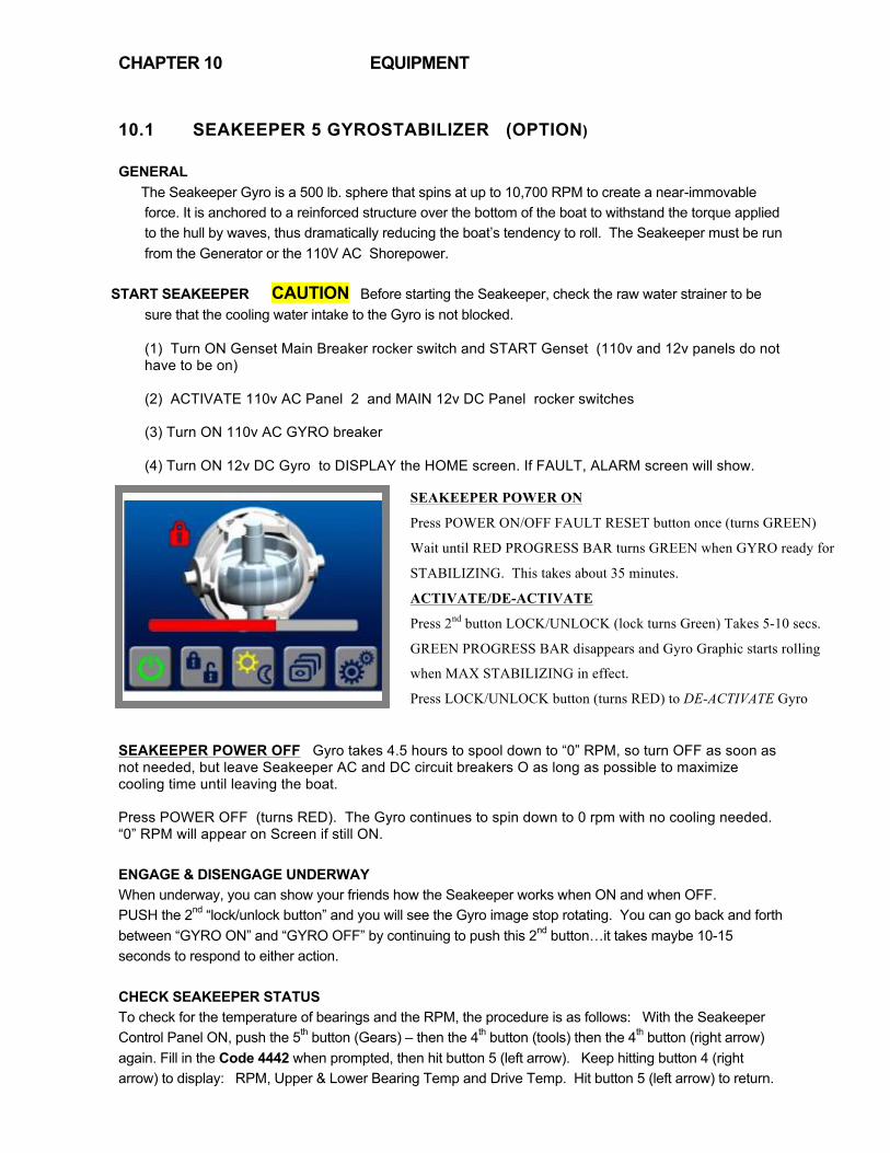
CHAPTER 10 EQUIPMENT
10.1 SEAKEEPER 5 GYROSTABILIZER (OPTION)
GENERAL The Seakeeper Gyro is a 500 lb. sphere that spins at up to 10,700 RPM to create a near-immovable
force. It is anchored to a reinforced structure over the bottom of the boat to withstand the torque applied to the hull by waves, thus dramatically reducing the boat’s tendency to roll. The Seakeeper must be run from the Generator or the 110V AC Shorepower.
START SEAKEEPER CAUTION Before starting the Seakeeper, check the raw water strainer to be
sure that the cooling water intake to the Gyro is not blocked.
(1) Turn ON Genset Main Breaker rocker switch and START Genset (110v and 12v panels do not have to be on) (2) ACTIVATE 110v AC Panel 2 and MAIN 12v DC Panel rocker switches (3) Turn ON 110v AC GYRO breaker (4) Turn ON 12v DC Gyro to DISPLAY the HOME screen. If FAULT, ALARM screen will show.
SEAKEEPER POWER OFF Gyro takes 4.5 hours to spool down to “0” RPM, so turn OFF as soon as not needed, but leave Seakeeper AC and DC circuit breakers O as long as possible to maximize cooling time until leaving the boat. Press POWER OFF (turns RED). The Gyro continues to spin down to 0 rpm with no cooling needed. “0” RPM will appear on Screen if still ON. ENGAGE & DISENGAGE UNDERWAY When underway, you can show your friends how the Seakeeper works when ON and when OFF. PUSH the 2nd “lock/unlock button” and you will see the Gyro image stop rotating. You can go back and forth between “GYRO ON” and “GYRO OFF” by continuing to push this 2nd button…it takes maybe 10-15 seconds to respond to either action. CHECK SEAKEEPER STATUS To check for the temperature of bearings and the RPM, the procedure is as follows: With the Seakeeper Control Panel ON, push the 5th button (Gears) – then the 4th button (tools) then the 4th button (right arrow) again. Fill in the Code 4442 when prompted, then hit button 5 (left arrow). Keep hitting button 4 (right arrow) to display: RPM, Upper & Lower Bearing Temp and Drive Temp. Hit button 5 (left arrow) to return.
SEAKEEPER POWER ON
Press POWER ON/OFF FAULT RESET button once (turns GREEN)
Wait until RED PROGRESS BAR turns GREEN when GYRO ready for
STABILIZING. This takes about 35 minutes.
ACTIVATE/DE-ACTIVATE
Press 2nd button LOCK/UNLOCK (lock turns Green) Takes 5-10 secs.
GREEN PROGRESS BAR disappears and Gyro Graphic starts rolling
when MAX STABILIZING in effect.
Press LOCK/UNLOCK button (turns RED) to DE-ACTIVATE Gyro

10.2 ANCHOR WINDLASS
Refer to the manual that came with your windlass for specific operating instructions. The windlass draws power from the engine start battery. It is therefore advisable to only use the windlass when the engine is running, and to allow time for the battery to recharge after windlass use. Never try to move the boat forward with the windlass- it is sized to retrieve the anchoring gear, not to pull the boat forward. If the windlass bogs down, use the boat’s engine to move directly over the anchor. If the anchor has become firmly lodged, use the boat’s engine to free it, then commence retrieval with the windlass. Note: always let the windlass come to a stop before reversing direction; otherwise, the windlass fuse/breaker may blow. To use the windlass, the engine start battery switch and house battery switch must both be ON and the windlass breaker on the panel must be ON.
To avoid chafe on the anchor rode when anchoring, it is advisable to remove the rode from the anchor chute by grabbing it below the roller, then pulling it up directly from the anchor, feeding it through a bow chock to a mooring cleat. Never rely on the windlass itself to hold the anchor rode- the chain stopper or a cleat should be used to take the load so as to avoid damaging the windlass’ gears. When not using the windlass or when underway, we recommend securing the anchor and chain with the anchor hook and line provided as standard to one of the mooring cleats. This prevents the anchor and rode from inadvertently running free underway and fouling the props. ANCHOR WASHDOWN A spray nozzle to wash saltwater or mud from the anchor rode and chain is located under the anchor roller. It is activated, when raising the anchor, by depressing a rocker switch on the switch panel on the piloting console. The Windlass and Water Pressure breakers must be ON.
10.3 STRATAGLASS PILOTHOUSE CURTAINS Do not use any chemicals or brushes to clean, only mild soap. If the curtains become scratched a mild polishing compound (a white cream similar to what is used on Awlgrip) can be applied by hand to remove them. Test a small, unobtrusive area first. WARNING The acid in gull droppings on the hardtop which then drizzle down the side curtains after a rain or heavy dew… and left for a period of time without washing….can irretrievably etch the clear Strata Glass curtains requiring them to be replaced at a cost of $2,000 or more each. There is one known instance with a 36z that was on a mooring in Chilmark on Martha’s Vineyard. Stuff is nasty. It is best to leave the curtains in place. But, if they are removed, be sure to always store curtains either flat or rolled together and not folded (to avoid creases).
-
- 39 -

CHAPTER 10
10.4 PRIVACY/SUNSCREEN CURTAINS (OPTION)
Fine white mesh allows you to see out but makes it difficult to see in as demonstrated below. When installed at night, these curtains convert the Pilothouse to an additional stateroom. The 2 Large side curtains now roll up in place. The other 4-6 curtains roll up in a carry bag. Aft and windshield curtain(s) hook/Velcro up inside. The two large side curtains can be deployed with StrataGlass curtains rolled up.
The advantage of inside curtains is that they don’t become dirty over time or require storage wet from dew when departing in the morning. Rolling of the curtains is best accomplished by laying over the top of the pilothouse table. Then roll all sections up together to place in the storage tube.
10.5 TRANSOM DOOR & SEAT (OPTION)
This transom door is intended for swimming, showering or stern boarding. When closed, you’d hardly know it was there. The starboard section of the standard ransom seat is now a moveable chair for après boating in the cockpit.
- 40 -
EXTERIOR EQUIPMENT

CHAPTER 10
10.6 STIDD SEAT POSITIONS
The two piloting seats are designed to swivel around and be lowered for a more sociable setting in the pilothouse. Be careful to slide the seats fully forward prior to swiveling so the seat is not jammed into the pilothouse sidewalls. Optional “Wide” Stidd Seats are available that function in the same manner.
10.7 WINDSHIELD OPERATION
While the triple windshield design creates individual windows that are smaller than those on the 34z, some owners have found that a stick with a rubber can tip is a handy way to push the windows out and assist in lowering them, without having to stretch over the console. Night or Fog If you haven’t discovered it already, it is possible to open the starboard window for unobstructed visibility and still travel at 14-15 knots without being blasted by the wind. Simply move slightly toward the centerline of the boat rather than directly behind the wheel to get out of the wind flow. POWER WINDSHIELDS (OPTION) These new windows opened to any angle by electric powered lineal actuators, unique to MJM, are a great addition to boating. One precaution, however, is that if left unused and closed for some time, there’s a tendency for them to stick and pop up when first opening. The remedy is to coat the gasket with a Teflon grease such as Snap & Zipper Lube. You will find that the windows shut with such a solid thunk, that it’s not necessary to go to the trouble of dogging them down along the bottom except in the roughest weather… not even when leaving the boat.
- 41 -
EXTERIOR EQUIPMENT

CHAPTER 11
11.1 MARINE VACUFLUSH HEAD SYSTEM
Waste discharge regulations vary by location. Check with local authorities.
The waste system aboard your boat employs freshwater and a vacuum generator. The freshwater pump breaker and Vacuflush breaker must both be ON (DC panel) for the system to work. Further controls are located on a panel in the head (shown). Refer to the manufacturer’s manual for more details. When the foot-pedal of the toilet is depressed, waste is drawn through the vacuum generator to the waste tank. Tank capacity is 20 gallons, which may seem small, but since each flush requires about a cup full of fresh water compared to the several quarts of sea-water using a conventional marine pump-head, the capacity is more than adequate and there’s no odor. Waste can be discharged two ways: (a) Via the shore-side pump-out fitting on the after-deck labeled WASTE using marina facilities. To effectively remove all the waste from the holding tank using, be sure to first turn OFF the vacuum pump system and step on the head flush pedal to remove all vacuum. (b) Offshore beyond restricted waste disposal zones by (1) OPENING the large waste thru-Hull discharge valve, accessible to starboard and aft under the cockpit, then (2) TURN & HOLD the switch in the Head to the right to activate overboard pumping using the macerator pump. The control panel lights indicate the level of waste in the holding tank. The level can be double- checked by viewing the dark waste line through the side of the semi-transparent holding tank.
Before activating this discharge, check to insure compliance with local regulations.
11.2 FRIDGE amd FREEZER
The DC Panel breaker for the Vitrifrigo double-fridge drawer unit must be ON. Temperature is controlled on the unit itself. Once on, the unit will self-regulate. It can take awhile for temperature to stabilize, particularly after initial stocking with food and beverages. (Photo is of a different unit) The separate top-load Indel freezer unit is capable of holding bags of marina ice or making ice in plastic trays.
11.3 KENYON TWO-BURNER CERAMIC COOKTOP
The galley cooktop aboard your boat is powered by AC electricity. To use it, make sure the “COOKTOP” breaker on the AC panel is ON and that a supply of AC power is present. This two-burner unit is unique in that it has flush-mount, pop-up, heat-resistant rubber pot holders.
Do not leave the cooktop ON while unattended.
- 42 -
EQUIPMENT

CHAPTER 11
11.4 SHARP GRILL 2 CONVECTION MICROWAVE
This unit offers several cooking modes which maybe operated without shorepower by utilizing the inverter for AC power and turning ON the MICROWAVE switch on AC Panel #1. Please refer to the Sharp Users Manual for operating instructions and precautions. The manual is stored inside the oven when the boat is initially delivered.
11.5 MARINE-AIR AIR-CONDITIONING UNITS (Optional)
This 16,000 BTU air-conditioning system can help keep the interior and pilothouse of the boat at comfortable temperatures by either cooling or using reverse cycle heat to act as a heater. The heat works particularly well to warm both the interior and pilothouse if the sea temperature is above 40 degrees. For a full explanation of the A/C controls, see the manufacturer’s user’s manual. To adjust fan speed range so that the lowest setting “1” is hardly noticeable and high-speed setting “6” is sufficient: Push the Fan Control button until “P1” shows. Then Press Star to select “P2” Press Up or Down Arrow until reading “65” Press Star to get to “P3” Press Up or Down Arrow until reading “40” The A/C system uses raw water, much like the engine, for heat exchange. There is an intake seacock, strainer & pump located in the Systems Room under the pilothouse. These should be checked frequently, and are the first things to check if the unit fails to deliver cold air.
11.6 WALLAS 40D DIESEL HEATER (Optional)
This heater is DC powered, controlled by a thermostat on the forward side of the entertainment center and draws diesel fuel from the starboard fuel tank. Please read the manual for instructions Do not use the Circuit Breaker Switch to turn off the Heater when it is operating. Before turning off the breaker switch, be sure to turn the control panel from heat to vent until the heating element has a chance to cool off.
11.7 FUSION 700 PLAYER (Optional) This multi-media unit operates on DC power. The STEREO breaker on the DC panel must be ON. See the instruction manual for operating details. This unit is also the CD and DVD player, with a single slot. It takes some getting used to… particularly the volume controls for different areas of the boat.
EQUIPMENT

CHAPTER 11
11.8 SIRIUS SATELLITE RADIO ACTIVATION (Optional)
To activate Sirius Satellite Radio services you will need to access the serial number. See instructions in the Fusion Manual:
11.9 22” LED TELEVISIONS (Optional) TV receivers operate with 120V AC Power. Turn ON the “TV” Breaker on the AC Panel. Click the “Menu” button and select Source. Video signals maybe acquired from the Fusion DVD player, from a dockside cable TV outlet, from a Glomax local TV antenna, or from the optional KVH satellite dish system. An access port is provided for MP3. Surround-Sound may be achieved using the “AUX” function on the Fusion Stereo Receiver to integrate both TV Audio and the 6 speaker stereo audio. Or, kids can watch TV with dedicated Audio belowdecks while parents are listening to jazz, with the “Fade” function directing sound to the 2 cockpit speakers. At right is the TV installation in the forward cabin. The optimum angle of viewing from the berth can be adjusted by turning the twist nut on the supporting arm. The cabinet behind the TV holds the “entertainment center” with the CD Changer, DVD Player, Satellite TV Receiver and the KVH Antenna if installed.
- 44 -
EQUIPMENT

CHAPTER 11
11.10 KVH M3 SATELLITE TV RECEIVER (Option)
To activate the receiver, turn ON the breaker labeled “Satellite Dish” on the DC Panel. Then be sure that the KVH dish control and receiver are turned on in the Entertainment Center. Follow the instructions in the KVH Owner’s Manual to initiate subscription and enjoy television reception aboard the boat. Either DISH Network or Direct TV has been selected prior to installation. The Dome and Radar unit mounted on the hard top must be removed for overland truck shipment. The procedure for installing the unit is described below:
KVH / RADAR DOME INSTALLATION INSTRUCTIONS (1) Run KVH and anchor light wires up through the KVH dome platform then fasten the base to the hardtop. See pic 1 below.
(2) Install the anchor light on the back of the strut and connect the Deutsch connector for the anchor light then push the remaining length of the anchor light wire (yellow and gray in Pic 1) back inside of the hole. The only cable that remains on top of the dome platform is the black RG6 cable for the KVH dome shown.
- 45 -
EQUIPMENT

CHAPTER 11
(3) Run the radar dome harness through the hole in the front of the strut, just behind where the radar dome will sit. See Pic 2 above.
(4) After installing the radar on it’s platform and running the harness inside the radar dome you will need to remove 5 screws from the top of the metal box (the cover will than hinge to the side-- see Pic 3) giving you access to the radar connections). You will have 2 red wires, 2 black wires and a plug with 7 smaller wires attached to it. (5) With a small flat head screwdriver loosen the positive and negative screws at the white terminal box. Plug the two red wires in the positive side and the two black wires in the negative side. The plug with the seven smaller wires will be plugged right in front of the white terminal box where the red and black wires are. See Pic 4. It can only plug in one direction. Make sure it’s connected and pushed in all the way and that the small gauge wires are in good conditions and not making too much of a bend. Slide the cover back in place (See Pic 5) and make sure the shield wires are sitting in the cable groove right at the edge of the opening. The grounding shield wires need to be sandwiched between the cover and the base of the metal box. Reinstall metal plate and radar dome cover. (6) Look for a yellow tag inside of the KVH dome with a screw; Very important, this screw is for shipping purpose only. This screw needs to be removed before you can run the unit
- 46 -
INTERIOR EQUIPMENT

CHAPTER 11 (7) Connect the RG6 cable to the 90º connector, located in the bottom of the KVH dome. Once this is done, mount the dome on the strut with the bolts provided.
- 47 -
INTERIOR EQUIPMENT
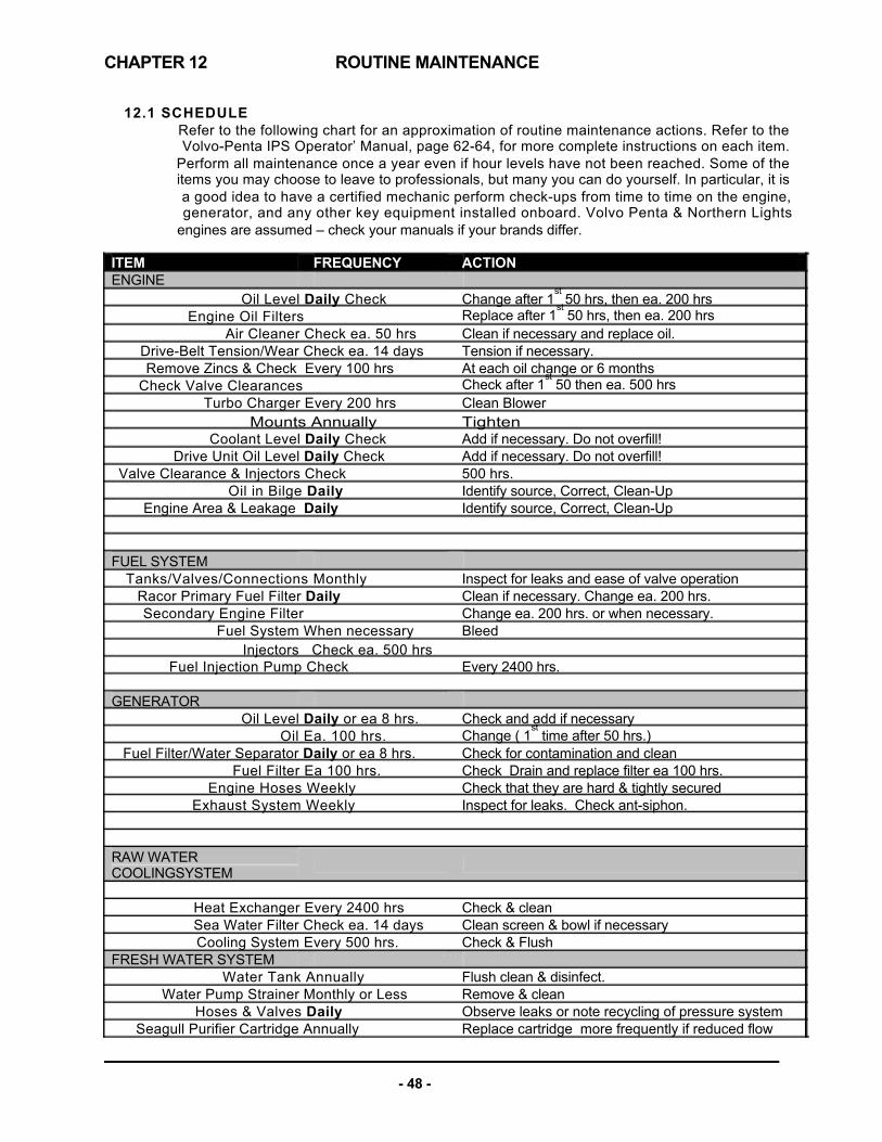
CHAPTER 12
ITEM ENGINE
Oil Level Daily Check Engine Oil Filters
Air Cleaner Check ea. 50 hrs Drive-Belt Tension/Wear Check ea. 14 days Remove Zincs & Check Every 100 hrs
Check Valve Clearances Turbo Charger Every 200 hrs
Mounts Annually Coolant Level Daily Check
Drive Unit Oil Level Daily Check Valve Clearance & Injectors Check
Oil in Bilge Daily Engine Area & Leakage Daily
FUEL SYSTEM
Tanks/Valves/Connections Monthly Racor Primary Fuel Filter Daily Secondary Engine Filter
Fuel System When necessary Injectors Check ea. 500 hrs
Fuel Injection Pump Check
GENERATOR Oil Level Daily or ea 8 hrs.
Oil Ea. 100 hrs. Fuel Filter/Water Separator Daily or ea 8 hrs.
Fuel Filter Ea 100 hrs. Engine Hoses Weekly
Exhaust System Weekly
RAW WATER COOLINGSYSTEM
Heat Exchanger Every 2400 hrs Sea Water Filter Check ea. 14 days Cooling System Every 500 hrs.
FRESH WATER SYSTEM Water Tank Annually
Water Pump Strainer Monthly or Less Hoses & Valves Daily
Seagull Purifier Cartridge Annually
- 48 -
ACTION
Change after 1st 50 hrs, then ea. 200 hrs
Clean if necessary and replace oil. Tension if necessary. At each oil change or 6 months Clean Blower Tighten Add if necessary. Do not overfill! Add if necessary. Do not overfill! 500 hrs. Identify source, Correct, Clean-Up Identify source, Correct, Clean-Up
Inspect for leaks and ease of valve operation Clean if necessary. Change ea. 200 hrs. Change ea. 200 hrs. or when necessary. Bleed Every 2400 hrs.
Check and add if necessary Check for contamination and clean Check Drain and replace filter ea 100 hrs. Check that they are hard & tightly secured Inspect for leaks. Check ant-siphon.
Check & clean Clean screen & bowl if necessary Check & Flush Flush clean & disinfect. Remove & clean Observe leaks or note recycling of pressure system Replace cartridge more frequently if reduced flow
12.1 SCHEDULE Refer to the following chart for an approximation of routine maintenance actions. Refer to the Volvo-Penta IPS Operator’ Manual, page 62-64, for more complete instructions on each item.
Perform all maintenance once a year even if hour levels have not been reached. Some of the items you may choose to leave to professionals, but many you can do yourself. In particular, it is a good idea to have a certified mechanic perform check-ups from time to time on the engine, generator, and any other key equipment installed onboard. Volvo Penta & Northern Lights
engines are assumed – check your manuals if your brands differ.
ROUTINE MAINTENANCE
FREQUENCY
Replace after 1st 50 hrs, then ea. 200 hrs
Check after 1st 50 then ea. 500 hrs
Change ( 1st time after 50 hrs.)
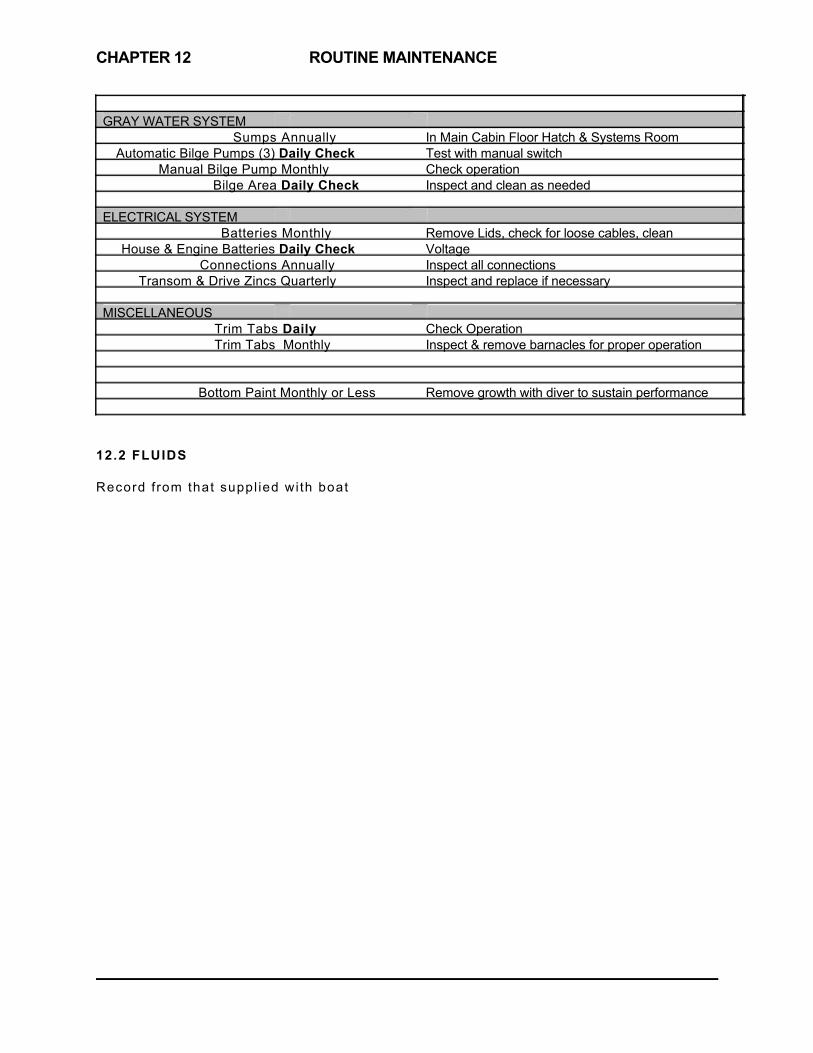
CHAPTER 12
GRAY WATER SYSTEM
Sumps Annually Automatic Bilge Pumps (3) Daily Check
Manual Bilge Pump Monthly Bilge Area Daily Check
ELECTRICAL SYSTEM
Batteries Monthly House & Engine Batteries Daily Check
Connections Annually Transom & Drive Zincs Quarterly
MISCELLANEOUS
Trim Tabs Daily Trim Tabs Monthly
Bottom Paint Monthly or Less
12.2 FLUIDS Record f rom that suppl ied wi th boat
- 49 -
In Main Cabin Floor Hatch & Systems Room Test with manual switch Check operation Inspect and clean as needed
Remove Lids, check for loose cables, clean Voltage Inspect all connections Inspect and replace if necessary
Check Operation Inspect & remove barnacles for proper operation
Remove growth with diver to sustain performance
ROUTINE MAINTENANCE
CHAPTER 13
13.1 START OF SEASON
[commissioning]
13.2 END OF SEASON
Most facilities will not require additional information before hauling the boat with a Travelift or crane, but if this is the case, use the included Lifting Diagram Figure 14.10. The end of the season is a good time to have the bottom power-washed and to check all thruhulls and seacocks for growth. Careful inspection of all underwater hardware at this point may avoid a potential problem in the future. This is also a good time to check the zincs of the boat and replace as necessary. If the boat is to be stored in a place where the ambient temperature may fall below the freezing point, it must be winterized. Plumbing lines need to be emptied and anti-freeze added where applicable. Consult also the engine operator’s manual.
- 50 -
SEASONAL MAINTENANCE

First Aid Kit
AC Raw Water Intake
Manual Bilge Pump
Fuel Shut-Off Valve
(over tanks)
EngineRoom Fireboy
Waste Discharge Thruhull
- 51 -
Electric Bilge Pump
Electric Bilge Pump Genset Raw Water Intake
Systems Room Fireboy Battery Disconnects
Fuel Shut-Off Valve (over tanks) Gen Set Separator Discharge Thruhull
Electric Bilge Pump
14.1 - EMERGENCY DIAGRAM

14.2 - 12 Volt DC WIRING DIAGRAM
- 52 -
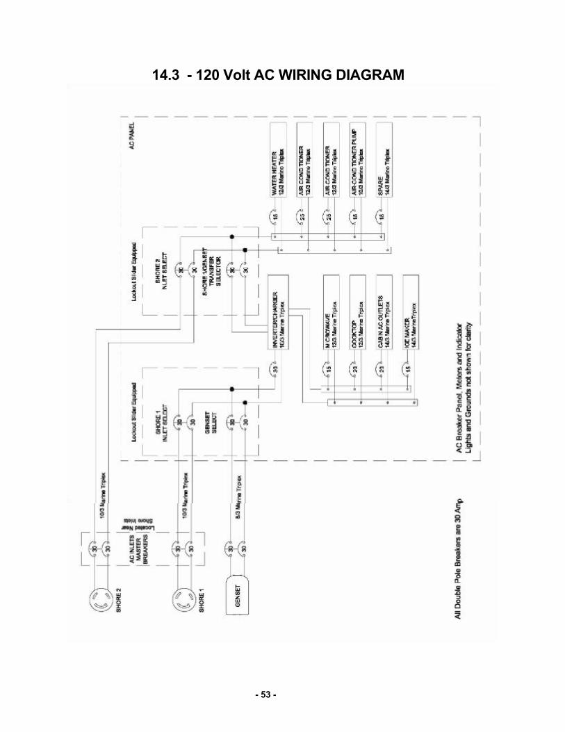
14.3 - 120 Volt AC WIRING DIAGRAM
- 53 -

14.4 - SYSTEMS DIAGRAM
- 54 -

14.5 - SYSTEMS KEY
- 55 -

FIGURE 14.6 – BOAT LIFT & BUNK OFFSETS
- 56 -

FIRGFIGUREF
TRAILER LOADING CHECKLIST
1. Place all cockpit & pilothouse cushions below on island berth. 2. Remove canvas from Bimini, detach aft legs and hinge the main hoop
forward against the hardtop. Secure the short legs, pad the main hoop where it touches the hardtop (AC hose) secure the hoop to handrails with fender whips.
3. Hinge down VHF antenna and reverse tape it to starboard handrail. 4. Hinge down running light and tighten. 5. Remove any KVH or FLIR tower and seal hardtop openings and wire
connections. Wrap domes and strut in blanket and securely park it in a pilothouse locker…or the shower, braced with throw pillows.
6. Max height over road is 13’6” which works for standard radar dome if bolted to hardtop without strut.
7. Wrap plastic around horn trumpets to avoid ingress of water. 8. Face searchlight aft and be sure that the anchor chain grabber is secure. 9. Be sure that all cabinet doors, drawers and fridge are latched securely shut. 10. Do not apply adhesive take directly to any surface particularly ultra leather. 11. Turn off all battery switches and make sure the Victron Control for the
inverter as well as the Unit over the Starboard Fuel tank are OFF. 12. NEVER PERMIT THE BOAT TO BE LOADED STERN FIRST . 13. Shrink wrapping is not recommended as it can do more damage if breaking
loose than it prevents. 14. Provide driver with detailed contact information so that he can remain in
contact with you and the destination yard. 15. In addition to aft and midship supports in locations seen on the previous
page, the boat should be supported under the bow, forward of any straps. 16. We’ve found that with the new zipper and track system that the the
StrataGlass side & aft curtains as well as the interior of the boat is better protected by leaving the side and aft pilothouse curtains down in place, rather than trying to remove and roll them up, then trying to find a secure place below.
17. Lock the companionway door and advise driver and receiving yard where the key is hidden.

CHAPTER 15 BOSTON BOATWORKS LIMITED WARRANTY
Manufacturer’s Sole and Limited Warranty for Pleasure craft
A. General. This document sets forth the sole and limited warranty, which Boston BoatWorks (“The Manufacturer”) is giving you in connection with the “Vessel” which you are acquiring. It is the only warranty being given by the Manufacturer and should be reviewed carefully together with manuals and other instructional material provided by the Manufacturer before you take delivery of the Vessel.
B. Basic Warranty. The Manufacturer warrants that the Vessel (except for Excluded items described below and when Properly Used, will be free of defects in material and workmanship for a period of twelve (12) months from delivery of the Vessel to you by an Authorized Dealer. If you sell the Vessel during this period, your buyer may receive the benefit of the balance of the warranty by agreeing to be bound by its terms.
C. Extended Warranty for Structure. In addition to the foregoing warranty, the Manufacturer warrants that the stringer systems, structural bulkheads and composite laminates of the Vessel (except for Excluded items) and when the Vessel is Properly Used, will be free of defects in material and workmanship for a period of five (5) years from delivery date by an Authorized Dealer. This warranty may be transferred to your buyer in the same manner as the Basic Warranty.
D. Extended Warranty Against Osmotic Blistering. In addition to the foregoing warranties, the Manufacturer warrants that any gelcoat surfaces of the Vessel below the waterline will not blister when the Vessel is Properly Used for a period of ten (10) years from delivery date by an Authorized Dealer. This warranty may be transferred to your buyer on the same manner as the Basic Warranty.
E. Dealers. The name and address of Authorized Dealers is available from the Manufacturer. The Manufacturer does not authorize the Dealer, or any other person, to assume for the Manufacturer any
liability in connection herewith or any liability or expense incurred in the repairing of its products other than those expressly authorized by the Manufacturer in writing.
F. Excluded Items. The Manufacturer gives no warranty as to:
a. Paints, varnishes, gelcoat (except where included in paragraph D above)a, exterior wood, vinyl, fabrics, glass, chrome plating or anodized or other finishes or surface coatings because of the varying quality of these items manufactured by others and the effect resulting from different climactic and use conditions
b. Engines, mechanical equipment, pumps, batteries, heating, plumbing, refrigeration, electronic components, masts, or other components manufactured by other than the Manufacturer, or the cost of removal or re-installment of the part and disassembly, or reassembly of the unit of which it is a component.
c. All items not installed by the Manufacturer or altered after their installation, and items installed or altered by Authorized Dealers.
d. Other than upon first being delivered, leaks in or around hatches, companionways, deck hardware or other leaks which are above the waterline.
e. Damage to the Vessel (including, but not limited to, wet core) caused by leakage around decks, hardware or other accessories attached to, or incorporated into, the Vessel.
f. Speed, fuel consumption or other performance characteristics, because they are estimated and not guaranteed.
G. Proper Use. The warranties contained herein are expressly conditioned upon your Proper Use of the
Vessel. This means that you must use the Vessel solely as a pleasure craft (no commercial use) and operate it as directed in and after reviewing the Manuals provided by the original equipment manufacturer and the
- 58 -

Manufacturer, and perform maintenance to the Vessel as recommended in the Manuals and as required by periodic inspections by an Authorized Dealer or Service Center.
H. Warranty Claims. To make a claim under this warranty you must do the following
a. Report the defect to the Manufacturer or Authorized Dealer within thirty (30) days of discovering it, and when possible prior to incurring any expense, identifying the Vessel and submitting photographs (email digital preferred).
b. Make the Vessel available for inspection by the Manufacturer or Authorized Dealer when requested.
c. Make the vessel available for repairs, if required, by the Manufacturer or Authorized Dealer. d. Major components, such as engines, generators, air-conditioners, electronics, appliances for
example are warranted by the manufacturer of the component. They have authorized service dealers in most major boating markets. The Manufacturer or Dealer will identify such service dealers upon request.
I. Repair or Replacement. The manufacturer shall perform its obligations under this warranty by, at it option, repairing or replacing (at Manufacturer’s expense) the defective part or component. Parts or components replaced will become the property of the Manufacturer. The replacement of parts o components will not extend the warranty but the replacement parts and components will be covered for the balance of the warranty period. You shall be responsible for returning the Vessel to Manufacturer at its plant or at a designated marina in the State of Massachusetts or to such other repair facility that the Manufacturer shall designate, at your sole expense.
J. Specification Changes. The manufacturer reserves the right to make changes in design, equipment, layout or construction without notice or being obligated to incorporate such changes in previous products.
K. Registration Cards. The Manufacturer recommends that you immediately fill out and return the Warranty Registration Card for the Vessel. The information contained on this card will enable the Manufacturer to more quickly process any warranty claims and to comply with the Federal Boating Safety Act. Should you sell the Vessel, the Manufacturer recommends that your buyer also fill or a Warranty Registration Card.
L. Exclusion of Implied Warranties. The foregoing warranty is intended to be in lieu of all other warranties, express or implied. In part, due to the hazardous, life-threatening environment, capable of overwhelming vessels of any size, that the Vessel will operate in, THE MANUFACTURER OR ITS DEALER DISCLAIMS ALL IMPLIED WARRRANTIES INCLUDING WARANTIES OF MERCHANTABILITY AND FITNESS FOR A PARTICULAR USE. In some jurisdictions, the Manufacturer is prohibited from excluding or limiting implied warranties. In those jurisdictions, the Manufacturer expressly limits any implied warranties to the greatest extent and to the shortest duration allowed by law.
M. Limitation of Damages. THE MANUFACTUER OR ITS DEALER DISCLAIMS ANY LIABILITY TO YOU FOR INCIDENTAL, CONSEQUENTIAL OR INDIRECT DAMAGES TO YOU, including loss of use, loss of revenue, travel expenses, transportation charges, food or lodging charges or loss of personal property. In some jurisdictions, the Manufacturer is prohibited from excluding or limiting implied warranties. In those jurisdictions, the Manufacturer expressly limits any implied warranties to the greatest extent and to the shortest duration allowed by law.
N. Whole Agreement. This warranty is the sole warranty given to you by the Manufacturer. Authorized Dealers are not authorized to make changes to this warranty. Any questions about the warranty should be directed to the Manufacturer. If you do bring a claim against the Manufacturer that is related to the Vessel, you must bring it in the Courts for the State of Massachusetts.
- 59 -
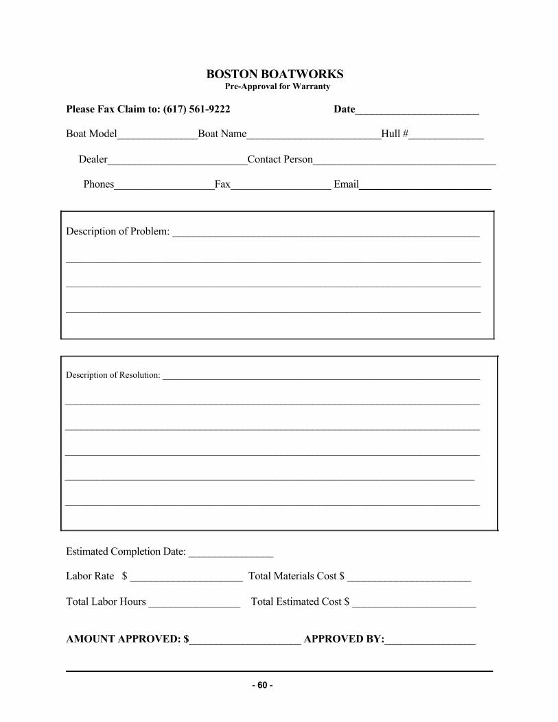
BOSTON BOATWORKS Pre-Approval for Warranty
Please Fax Claim to: (617) 561-9222 Date_______________________ Boat Model_______________Boat Name_________________________Hull #______________
Dealer__________________________Contact Person__________________________________
Phones___________________Fax___________________ Email_________________________
Description of Problem: _________________________________________________________
_____________________________________________________________________________
_____________________________________________________________________________
_____________________________________________________________________________
Description of Resolution: _______________________________________________________________________
_____________________________________________________________________________
_____________________________________________________________________________
_____________________________________________________________________________
____________________________________________________________________________
_____________________________________________________________________________
Estimated Completion Date: ________________ Labor Rate $ _____________________ Total Materials Cost $ _______________________
Total Labor Hours _________________ Total Estimated Cost $ _______________________
AMOUNT APPROVED: $_____________________ APPROVED BY:_________________
- 60 -
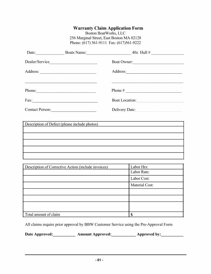
Warranty Claim Application Form Boston BoatWorks, LLC
256 Marginal Street, East Boston MA 02128 Phone: (617) 561-9111 Fax: (617)561-9222
Date:______________ Boats Name:______________________ 40z Hull # ________________
Dealer/Service_______________________
Address: ____________________________
___________________________________
Phone:_____________________________
Fax:_______________________________
Contact Person:______________________
Description of Defect (please include photos)
Description of Corrective Action (include invoices) Labor Rate: Labor Cost: Material Cost:
Total amount of claim
All claims require prior approval by BBW Customer Service using the Pre-Approval Form
Date Approved:___________ Amount Approved:____________ Approved by:___________
- 61 -
Boat Owner:_________________________
Address:____________________________
___________________________________
Phone # ____________________________
Boat Location:_______________________
Delivery Date:_______________________
Labor Hrs:
$

CHAPTER 16 QUICK START GUIDE
1 - Disconnect Shore-side Connections To disconnect shore power cords, turn off all AC loads on the boat and make sure the main AC breakers on the AC panel (the double breakers) are all OFF. Then disconnect the cord at the dock end first. Disconnect the cord at the boat and close the shore power inlet cover. Ditto for any phone/cable TV lines and dock water inlet..
2 - Set Battery Switches
The Engine battery selector switches are at the top of the AC electrical panel. Slide the covers down and Push Start STBD engine switch and Start PORT engine switch, both ON. Be sure that the HOUSE battery switch on the DC panel is also ON. Unless running the generator underway, the GENERATOR switch should be OFF with the cover slid upwards. If the engine start battery is low the Combiner switch can be turned on until underway, then turned OFF.
Remember to turn all switches OFF when leaving the boat, except the HOUSE battery switch, if needed to keep the Refrigeration going.
3 - Check Engine
It is advisable to check the engine fluid levels before starting the engine. Refer to the Owner’s Manual for instructions on lifting the engine hatch cover and checking the oil coolant and transmission levels.
4 - Check Raw Water Seacock
Make sure that the raw water seacocks are in the position to supply the engine with seawater for cooling. It is also advisable to check to see a good surge of water through the plexiglass top of the raw water strainers on top of the engines.
5 - Visually Inspect the Engine Room
While doing other checks, it is a good idea to take a look around the engine for loose belts, wires, oil drips or water in the bilge or anything else that may be out of order.
- 62 -

6 - Check DC Panel
Check the DC panel to insure that the house bank has a reasonable charge (12.2V or greater). If there is any problem, now is the time to learn of it. Make sure the DC MAIN breaker is ON, as well as any other circuits that you might need in the course of your trip. If you need the searchlight in a hurry, for instance, it’s better to have the breaker already on.
7 - Turn ON Navigation Instruments
Turn on TRIM TABS, NAV INSTRUMENTS, HORN, WIPERS.
8 - Check Lights
If the boat is to be operated after sunset or in reduced visibility or fog, TURN on NAVIGATION LIGHTS & SEARCHLIGHT and check that they are working.
9 - Start Engine
See earlier pages in this Owner’s Manual for specific instructions for operating these new electronically controlled engines.
10 - Check IPS, Steering and Trim Tab Function
With the engine controls in Neutral, push the left “Docking: button under the IPS joystick and listen for a confirming beep. Briefly test its operation with a slight tap in any direction.
Make sure that no one is on the foredeck or handling a dock-line
when this test is performed. Also check that the trim tabs are working properly, and that the steering turns smoothly.
11 - Final Checks
12 - Casting Off
When you are confident that everything is in order, cast off all dock lines and when maneuvering with the IPS joystick remember that a light touch (taps) on the joy stick with short bursts are usually sufficient to move the boat in the direction desired.
- 63 -
Before departing, make sure the engine and house batteries are being charged. (Note: by design, there is a delay between starting the engine and alternator charging.) Make sure your navigation plans have been prepared and that all equipment is functioning (even that which you don’t necessarily intend to use). Check your fuel and water levels. Be sure the anchor is secured.