Influvence of Alloying Additions on the Structure and ...
189
INFLUENCE OF ALLOYING ADDITIONS ON THE STRUCTURE AND PROPERTIES OF AI-7Si-O.3Mg ALLOY Thesis submitted to Cochin University of Science and Technology in partial fulfilment of the requirements for the Degree of DOCTOR OF PHILOSOPHY By SREEJA KUMARI. S.S MATERIALS AND MINERALS DIVISION REGIONAL RESEARCH LABORATORY (CSIR) THIRUVANANTHAPURAM - 695 019 INDIA April 2006
Transcript of Influvence of Alloying Additions on the Structure and ...

INFLUENCE OF ALLOYING ADDITIONS ON THE STRUCTURE AND PROPERTIES
OF AI-7Si-O.3Mg ALLOY
Thesis submitted to Cochin University of Science and Technology
in partial fulfilment of the requirements for the Degree of
DOCTOR OF PHILOSOPHY
By SREEJA KUMARI. S.S
MATERIALS AND MINERALS DIVISION REGIONAL RESEARCH LABORATORY (CSIR)
THIRUVANANTHAPURAM - 695 019 INDIA
April 2006

COUNCIL OF SCIENTIFIC AND INDUSTRIAL RESEARCH
REGIONAL RESEARCH LABORATORY Industrial Estate P.O., Thiruvananthapuram - 695019, India Telegram: Consearch, Fax: 0471-2490186, 2491712 Email: [email protected]; Phone: 0471-2490674, 2490811
Dr. R.M. Pillai Senior Deputy Director and Head Materials and Minerals Division
CERTIFICATE
This is to certify that the thesis entitled 'Influence of Alloying Additions on
the Structure and Properties of AI-7Si-O.3Mg Alloy' embodies the results of
bonafide research work carried out by Mrs. Sreeja Kumari S.S. for the degree of
Doctor of Philosophy in the Faculty of Technology of the Cochin University of
Technology under my guidance. The content of this thesis or part thereof has not been
submitted to any other university or institute for the award of any degree or diploma.
(R.M. Pillai) Thesis Supervisor
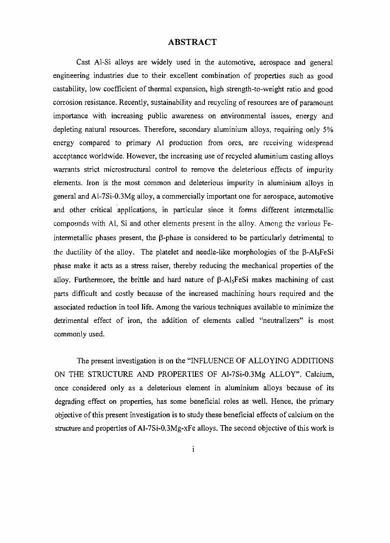
ABSTRACT
Cast AI-Si alloys are widely used in the automotive, aerospace and general
engineering industries due to their excellent combination of properties such as good
castability, low coefficient of thermal expansion, high strength-to-weight ratio and good
corrosion resistance. Recently, sustainability and recycling of resources are of paramount
importance with increasing public awareness on environmental issues, energy and
depleting natural resources. Therefore, secondary aluminium alloys, requiring only 5%
energy compared to primary AI production from ores, are receiving widespread
acceptance worldwide. However, the increasing use of recycled aluminium casting alloys
warrants strict microstructural control to remove the deleterious effects of impurity
elements. Iron is the most common and deleterious impurity in aluminium alloys in
general and AI-7Si-O.3Mg alloy, a commercially important one for aerospace, automotive
and other critical applications, in particular since it fonns different intennetallic
compounds with AI, Si and other elements present in the alloy. Among the various Fe
intennetallic phases present, the l3-phase is considered to be particularly detrimental to
the ductility Of the alloy. The platelet and needle-like morphologies of the I3-AI5FeSi
phase make it acts as a stress raiser, thereby reducing the mechanical properties of the
alloy. Furthennore, the brittle and hard nature of I3-AI5FeSi makes machining of cast
parts difficult and costly because of the increased machining hours required and the
associated reduction in tool life. Among the various techniques available to minimize the
detrimental effect of iron, the addition of elements called "neutralizers" is most
commonly used.
The present investigation is on the "INFLUENCE OF ALLOYING ADDITIONS
ON THE STRUCTURE AND PROPERTIES OF AI-7Si-0.3Mg ALLOY". Calcium,
once considered only as a deleterious element in aluminium alloys because of its
degrading effect on properties, has some beneficial roles as well. Hence, the primary
objective of this present investigation is to study these beneficial effects of calcium on the
structure and properties of AI-7Si-0.3Mg-xFe alloys. The second objective of this work is

to study the effects of Mn, Be and Sr addition as Fe neutralizers and also to study the
interaction of Mn, Be, Sr and Ca in AI-7Si-0.3Mg-xFe alloys. The structure of the thesis
and the details of the studies are given below.
The Chapter 1 deals with the general introduction to AI-Si alloys, AI-Si phase
diagram and the applications of these alloys. Further, the importance of recycling has
been brought out towards the end of this chapter.
A comprehensive revIew of the parameters influencing the structure and
properties of AI-Si-Mg cast alloys is given in Chapter 2. This chapter also presents an
extensive literature survey on the effect of iron in AI-Si foundry alloys and the methods
of eliminating the deleterious effects of iron. Further, this review mainly focuses on the
literature available on calcium besides the common iron neutralizing elements in AI-Si
Mg cast alloys.
Chapter 3 gives the details of the materials and the experimental methods used in
the present investigation. The structural characteristics of the castings are evaluated by
optical metallography coupled with Image analyser, Scanning Electron Microscopy and
Energy Dispersive X-ray spectroscopy, and X-ray Diffraction analysis. Solidification
behaviour was studied by Thermal Analysis and Differential Thermal Analysis. The
physical properties such as density and electrical conductivity are measured using
Archimedean densitometry and TECHNOFOUR conductivity meter respectively.
Mechanical properties (tensile and impact) are evaluated using Instron Universal Testing
Machine and Pendulum Type Charpy Impact Testing Machine.
Chapter 4 deals with results of the dual effect of calcium viz., Modification and
Fe-neutralization in AI-7Si-0.3Mg alloy. It has been found that calcium modifies the
eutectic Si by changing its morphology from acicular to fine fibrous form and the tensile
and impact properties obtained are at par with those obtained with the well known
modifier viz., Sr. Ca refines the platelet Fe-intermetallic phases causing improved
ii

electrical conductivity, elongation and impact strengths. The proposed mechanism for Fe
neutralization by Ca is the destabilization of the j3-phase and fragmentation of the long
~-platelets into smaller sizes. One of the interesting observations in the present work is
that a low level of calcium reduces the porosity compared to the untreated alloy.
However, higher levels of calcium addition lead to higher porosity in the castings. An
empirical analysis carried out for comparing the results of the present work with those of
the other researchers on the effect of increasing iron content on UTS and % elongation of
Al-Si-Mg and AI-Si-Cu alloys has shown a linear and an inverse first order polynomial
relationships respectively.
Chapter 5 deals with the effects of Mo, Be and Sr as Fe-neutralizers and their
interaction with calcium in AI-7Si-0.3Mg-xFe alloy. Mn and Be additions to AI-7Si
O.3Mg-xFe alloys change the morphology of platelet iron phase to Chinese script form,
whereas Sr reduced the size of platelet phases like Ca. This has led to a significant
improvement in tensile properties with Mn addition and both tensile and impact
properties with Be and Sr additions. Combined additions of Ca + Mo, Be + Mo and Sr +
Mn led to improvement in both tensile and impact properties compared to individual
additions and a synergistic effect of both the elements is achieved. A trace amount of Be
(0.005%) addition to Ca leads to superior tensile properties compared to Ca addition
alone.
The summary of the findings of this investigation along with its contributions
made to the knowledge and the avenues for further work are presented in Chapter 6.
iii

CONTENTS
Abstract
Acknowledgements
Contents
List of Tables
List of Figures
CHAPTER 1: INTRODUCTION
1.1 IMPORTANCE OF AI-Si ALLOYS
1.2 AI-Si ALLOY SYSTEM
1.3 RECYCLING OF ALUMINIUM AND ITS ALLOYS
CHAPTER 2: LITERATURE REVIEW
2.1 INTRODUCTION
2.2 PARAMETERS INFLUENCING THE STRUCTURE AND PROPERTIES OF AI-Si-Mg CAST ALLOYS
2.2.1 Alloy Composition
2.2.1.1 Major alloying elements
2.2.1.2 Trace alloying elements
2.2.1.3 AI-7Si-0.3Mg alloy
2.2.2 Solidification Characteristics
2.2.3 Casting Defects and their Control
2.2.3.1 Gas porosity
2.2.3.2 Shrinkage porosity
2.2.4 Melt Treatments
2.2.4.1 Degassing
2.2.4.2 Modification
2.2.4.3 Grain refmement
2.2.5 Effect of Alloying Elements on the Castability of Aluminium Alloys
2.2.5.1 Formation of oxides and their effects
2.2.5.2 Fluidity
2.2.6 Heat Treatment
2.2.6.1 Temper selection
vi
Page No. I
IV
VI
x
Xl
1
2
2
4
8
8
8
8
8
9
11
11
14
16
19
20
20
21
29
30
30
31
34
34
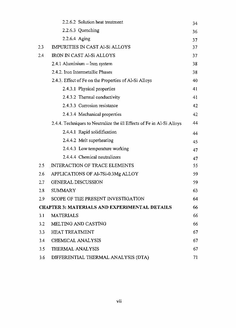
2.2.6.2 Solution heat treatment 34
2.2.6.3 Quenching 36
2.2.6.4 Aging 37
2.3 IMPURITIES IN CAST AI-Si ALLOYS 37
2.4 IRON IN CAST AI-Si ALLOYS 37
2.4.1 Aluminium - Iron system 38
2.4.2. Iron Intermetallic Phases 38
2.4.3. Effect of Fe on the Properties of AI-Si Alloys 40
2.4.3.1 Physical properties 41
2.4.3.2 Thermal conductivity 41
2.4.3.3 Corrosion resistance 42
2.4.3.4 Mechanical properties 42
2.4.4. Techniques to Neutralize the ill Effects of Fe in AI-Si Alloys 44
2.4.4.1 Rapid solidification 44
2.4.4.2 Melt superheating 45
2.4.4.3 Low temperature working 47
2.4.4.4 Chemical neutralizers 47
2.5 INTERACTION OF TRACE ELEMENTS 55
2.6 APPLICATIONS OF AI-7Si-0.3Mg ALLOY 59
2.7 GENERAL DISCUSSION 59
2.8 SUMMARY 63
2.9 SCOPE OF THE PRESENT INVESTIGATION 64
CHAPTER 3: MATERIALS AND EXPERIMENTAL DETAILS 66
3.1 MATERIALS 66
3.2 MELTING AND CASTING 66
3.3 HEAT TREATMENT 67
3.4 CHEMICAL ANAL YSIS 67
3.5 THERMAL ANALYSIS 67
3.6 DIFFERENTIAL THERMAL ANAL YSIS (DTA) 71
vu

3.7 PHYSICAL CHARACTERISTICS 71
3.7.1 Density Measurement and Porosity Calculation 71
3.7.2 Electrical Conductivity 71
3.8 MECHANICAL CHARACTRISTICS 72
3.9 STRUCTURAL STUDIES 72
3.9.1. Optical Microscopy 72
3.9.2. image Analysis 74
3.9.3. Scanning Electron Microscopy (SEM)/ Energy Dispersive X- 74 ray Spectroscopy (EDS)/ Electron Back Scattered Diffraction (EBSD)
CHAPTER 4: EFFECT OF CALCIUM IN AI-7Si-O.3Mg ALLOY 75
4.1 MODIFICATION 75
.4.1.1 Methodology 75
4.1.2 Results and Discussion 76
4.1.2.1 Microstructure 76
4.1.2.2 Physical characteristics 76
4.1.2.3. Mechanical properties 80
4.1.3 SUMMARY 82
4.2 IRON NEUTRALIZATION
4.2.1 Methodology
4.2.2 Results
4.2.2.1 Microstructure
4.2.2.2 Physical characteristics
4.2.2.3 Mechanical properties
4.2.3 Empirical Analysis of Data
4.2.4 Discussion
4.2.5 Summary
CHAPTER 5: EFFECT OF Mn, Be AND Sr AND THEIR INTERACTION WITH Ca IN AI-7Si-O.3Mg-xFe ALLOY
5.1 INTRODUCTION
5.2 METHODOLOGY
5.3 RESULTS
5.3.1 Microstructure
Vlll
84
84
84
84
89
94
102
106
110
111
111
111
112
112

5.3.1 Microstructure 112
5.3.1.1 Effect ofMn, Be and Sr 112
5.3.1.2 Interaction ofMn, Be, Sr and Ca 115
5.3.2 Solidification Behaviour 128
5.3.2.1 Thermal analysis 128
5.3.2.2 Differential thermal analysis 128
5.3.3 Physical Characteristics 138
5.3.3.1 Porosity 138
5.3.3.2 Electrieal conductivity 138
5.3.4 Mechanical Properties 139
5.3.4.1 Tensile properties 139
5.3.4.2 Impact strength 142
5.4 DISCUSSION 145
5.5 SUMMARY 150
CHAPTER 6: CONCLUSIONS 151
6.1 SIGNIFICANT CONTRIBUTIONS OF THE PRESENT 153 INVESTIGATION TO THE KNOWLEDGE
6.2 AVENUES FOR FUTURE WORK. 153
REFERENCES 154
AWARDS AND PUBLICATIONS BASED ON THE THESIS WORK 171
IX

LIST OF TABLES
Table Caption Page Number Number
1.1 Common AI-Si alloys and their mechanical properties 5
2.1 Various Designations of AI-7Si-0.3Mg alloy 12
2.2 Physical properties of LM25 I AI-7Si-0.3Mg alloy 12
2.3 Mechanical properties ofLM25/AI-7Si-0.3Mg alloy 13
2.4 Characteristics of elements used as eutectic silicon modifiers 25 in Al-Si alloys
2.5 Mechanical Properties ofNa and Ca added Silumin (Eutectic 27 Alloy Containing 11.59% Si)
2.6 Atomic size, crystal structure and maximum solid solubility of 48 various elements in pure aluminium at eutectic/peritectic temperature
2.7 Optimum amount, morphological change, advantages and 49 limitations of various iron neutralizers in AI-Si alloys
3.1 Chemical composition (wt.%) of the AI-7Si-0.3Mg 66 . (LM25/356) alloy
4.1 % Porosity and Electrical Conductivity of Al-7Si-0.3Mg alloy 80 treated without and with Ca
4.2 Silicon particle characteristics of T6-heat treated samples 88
4.3 Fitted equation and the correlation coefficient for the plot of 93 % porosity versus % Fe content at various Ca levels
4.4 Empirical analysis of data for UTS versus Fe content 104
4.5 Empirical analysis of data for % elongation versus Fe content 105
5.1 Average length of eutectic Si in Al-7Si-0.3Mg-l.0Fe alloy 123 without and with Ca, Be and Ca+Be additions
5.2 Alloys, thermal arrests and the phases formed in AI-7Si- 134 0.3Mg-0.8Fe alloy without and with Be, Mn, Ca and Sr additions
5.3 % porosity and electrical conductivity of permanent mould 139 cast AI-7Si-0.3Mg-0.6Fe alloy without and with Ca, Mn and Ca + Mn additions
x

LIST OF FIGURES
Figure Caption Page Number Number
1.1 Aluminium's Major Applications 3
1.2 AI-Si alloy phase diagram 3
2.1 Effect of alloying elements on the surface tension of 99.99 15 aluminium at 973 to 1013 K in argon atmosphere
2.2 The solubility of hydrogen at one atmosphere pressure in pure 17 aluminium
2.3 Ledge migration mechanism responsible for the growth of Si 22 flakes bounded by atomically flat (111) surfaces
2.4 Plot of atomic radii vs atomic number, with range of radii 23 which includes elements capable of producing silicon modification - shaded
2.5 Schematic representation of impurity atoms pinning the steps 23 of a silicon crystal growing by the layer growth mechanism at the solidlliquid interface
2.6 Microporosity and macroporosity in modified and unmodified 28 A357 alloy
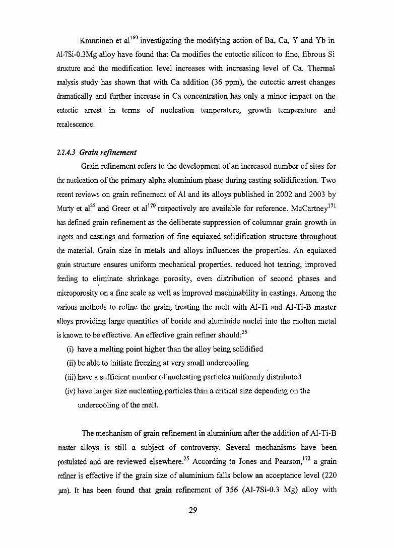
2.7 Microstructure of AI-Si-Mg (356) alloy after grain refining 33 with AI-5Ti-1B master alloy
2.8 Comparative oxidation losses caused by the addition of 33 various elements to aluminium melt
2.9 Equilibrium solubility ofMg and Si in solid aluminium when 35 both Mg2Si and Si are present
2.10 AI-Fe alloy phase diagram 39
2.11 Liquidus surfaces in the AI-rich corner of the AI-Fe-Si 39 equilibrium phase diagram
2.12 Micrographs of AI-6Si-3.5Cu-1.0Fe alloy (a) superheated to 46 1023 K and (b) 1123 K prior to casting (cooling rate = 283 Kls)
Xl

2.13
2.14
2.15
2.16
2.17
3.1
3.2
3.3
3.4
3.5
4.1
4.2
4.3
4.4
4.5
4.6
Simplified illustration of Fe segregation during solidification of356 (AI-7Si-0.3Mg) alloy containing 0.48% Fe
Tmat and dynamic fracture toughness versus Fe content in AC2B-T6 (AI-6.5Si-4Cu) casting alloy with and without Ca addition
Cooling curves obtained when Ca is used in the presence of Sr
Aura alloy wheel - PCD 1 08 (Hindalco) used in TAT A Indica and Ford Ikon cars
Premium quality AI-7Si-0.3Mg (A356) alloy castings for Space application (PSLV & GSLV Programmes of ISRO)
Dimensions of (a) Rectangular slab mould and (b) Cylindrical mould used
Dimensions of (a) Rectangular slab casting and (b) Cylindrical castings
MeltLab Aluminium Thermal Analyser
DT A equipment
TECHNOFOUR' conductivity meter
Typical as cast microstructures of AI-7Si-0.3Mg alloy treated (a) without and (b) with 0.01 % Ca
Typical as cast microstructures of AI-7Si-0.3Mg alloy treated (a) 0.02 % Ca (b) 0.05% Ca and (c) 0.02% Sr
(a) SEM photograph of AhCaSi2 phase in AI-7Si-0.3Mg alloy treated with 0.05% calcium (b) EDS spectra showing the distribution of AI, Si and Ca in AhCaSh phase
Effect of calcium on the (a) UTS (b) % elongation and (c) impact strength of AI-7Si-0.3Mg alloy
SEM micrographs showing the impact fracture surface of AI-7Si-0.3Mg alloy with and without Ca (a) 0% Ca (b) 0.01% Ca (c) 0.02% Ca (d) 0.05% Ca and (e) 0.02% Sr
Typical permanent mould as cast microstructures of AI-7SiO.3Mg alloy with (a) 0.4 and (b) 0.7% Fe
Xll
51
56
56
60
61
68
69
70
73
73
77
78
79
81
83
85

4.7 (a) SEM photograph of p-phase in Al-7Si-0.3Mg-0.7Fe alloy 86 and (b) EDS spectra showing the distribution of AI, Si and Fe
4.8 Typical microstructures of sand cast AI-7Si-0.3Mg alloy with 87 (a) 0.2% Fe, (b) 0.7% Fe, (c) 0.2% Fe + 0.01% Ca and (d) 0.7% Fe + 0.01 % Ca in the as-cast condition
4.9 Effect of Ca addition on the average length of the p-phase 90 particles in sand cast AI-7Si-0.3Mg-xFe alloy
4.10 Typical microstructures of AI-7Si-0.3Mg-0.6Fe alloy treated 90 with 0.05% Ca
4.11 SEM micrograph showing very fine Fe intennetallic phases in 91 AI-7Si-0.3Mg-0.6Fe alloy with Ca (0.05%) addition
4.12 (a) SEM micrograph showing the fonnation of AhCaSh 91 phase in Al-7Si-0.3Mg-0.6Fe alloy with Ca (0.05%) addition (b) EDS spectrum showing AI, Si and Ca distributions.
4.13 Typical microstructures of pennanent mould cast AI-7Si- 92 0.3Mg-0.7Fe alloy in T6 condition (a) without and (b) with 0.01% Ca
4.14 EBSD mappmg results of AI-7Si-0.3Mg-0.2Fe+0.Ol% Ca 92 alloy
4.15 Effect of Ca on the % porosity of AI-7Si-0.3Mg-xFe alloy 93
4.16 Micrographs of platelet/needle like Fe intennetallic 95 compound observed within a shrinkage pore in AI-7Si-0.3Mg-0.7Fe alloy (a) Optical and (b) SEM
4.17 Effect of Ca on the %IACS of AI-7Si-0.3Mg-xFe alloy 96
4.18 Effect of Ca addition on the (a) UTS and (b) % elongation of 97 AI-7Si-0.3Mg-xFe alloy (T6 condition)
4.19 SEM micrographs showing the tensile fractured surface of 99 AI-7Si-0.3Mg alloy (T6 condition) containing (a) 0.2% Fe (b) 0.2% Fe+0.005% Ca (c) 0.4% Fe+O.Ol% Ca and d) 0.7% Fe+0.005% Ca
4.20 Effect of Ca on the quality index of AI-7Si-0.3Mg-xFe alloy 100 in T6 condition
4.21 Effect of Ca on the impact strength of AI-7Si-0.3Mg-xFe 101 alloy
Xlll

4.22 Effect of higher amount of Ca (0.05%) on the (a) UTS 103 (b) % elongation and (c) impact strength of AI-7Si-0.3Mg-0.6Fe alloy (T6 condition)
4.23 Empirical analysis of the variation of UTS with iron content 104 in AI-Si-Mg and AI-Si-Cu alloys
4.24 Empirical analysis of the variation of % elongation with iron 105 content in AI-Si-Mg and AI-Si-Cu alloys
4.25 Schematic illustration of decomposition of 13 platelets with 107 Ca addition
5.1 Typical microstructures of permanent mould cast AI-7Si- 113 0.3Mg alloy with (a) 0.8% Fe, Circled area showing the branching of l3-platelet and (b) Higher magnification of the branched platelet, arrow showing nucleation of eutectic Si by l3-platelets
5.2 Typical microstructures of permanent mould cast AI-7Si- 114 0.3Mg-0.6Fe alloy treated with (a) 0.3% Mn and (b) 0.5% Mn [Arrows show the Mn-Fe phases]
5.3 SEM micrograph of AI-7Si-0.3Mg-0.8Fe with 0.3% Mn 114 addition
5.4 EDS elemental X-ray mapping and elemental distribution of 116 Chinese script Mn-Fe phase in AI-7Si-0.3Mg-0.6Fe alloy treated with 0.3% Mn
5.5 Typical as cast microstructures of permanent mould cast 117 AI-7Si-0.3Mg-0.8Fe-0.2Be alloy
5.6 Typical microstructure of sand cast Al-7Si-0.3Mg-1.0Fe- 117 0.2Be alloy
5.7 X-ray diffraction patterns of (a) AI-7Si-0.3Mg-0.8Fe and 118 (b) AI-7Si-0.3Mg-0.8Fe-0.2Be alloys
5.8 Typical microstructures of permanent mould cast Al-7Si- 119 0.3Mg-0.8Fe alloy treated with 0.04% Sr (a) Optical and (b) SEM micrographs
5.9 Typical microstructures of permanent mould cast Al-7Si- 120 0.3Mg-0.6Fe-0.3Mn alloy with (a) 0.02 (b) 0.05 and (c) 0.08% Ca
XIV

5.10 Typical permanent mould cast microstructure of AI-7Si- 122 0.3Mg-0.8Fe alloy with Be (0.005%)+Ca (0.04%) addition
5.11 Typical sand mould cast microstructures of AI-7Si-0.3Mg- 122 1.0Fe alloy treated with (a) 0.015% Ca+0.005% Be and (b) 0.008% Ca + 0.007% Be ["I"-Platelet form of iron intermetallic compound]
5.12 Average length of ~ phase in AI-7Si-0.3Mg-l.0Fe alloy 123 without and with Ca, Be and Ca + Be additions
5.13 SEM micrograph of AI-7Si-0.3Mg-0.8Fe alloy with 124 Be (0.15%) + Mn (0.15%) addition
5.14 Typical microstructure of permanent mould cast 124 AI-7Si-0.3Mg-0.8Fe alloy with Mn (0.3%) + Sr (0.04%) addition
5.15 EDS elemental X-ray mapping and elemental distribution of 125 Chinese script Mn-Fe phase in AI-7Si-0.3Mg-0.8Fe alloy with Be (0.15%) + Mn (0.15%)
5.16 Typical microstructures of AI-7Si-0.3Mg-0.8Fe alloy in T6 126 condition (a) without and (b) with 0.4% Mn
5.17 Typical microstructures of AI-7Si-0.3Mg-0.8Fe alloy in T6 127 condition with (a) 0.2% Be and (b) 0.04% Sr
5.18 (a) Cooling curve and its first derivative and 129 (b) microstructures of AI-7Si-0.3Mg-0.8Fe alloy thermal analysis sample
5.19 (a) Cooling curve and its first derivative and 130 (b) microstructures of AI-7Si- 0.3Mg-0.8Fe-0.2Be alloy thermal analysis sample
5.20 (a) Cooling curve and its first derivative and 131 (b) microstructures of AI-7Si-0.3Mg-0.8Fe-0.4Mn alloy thermal analysis sample
5.21 (a) Cooling curve and its first derivative and 132 (b) microstructure of AI-7Si-0.3Mg-0.8Fe-0.04Ca alloy thermal analysis sample (arrows show ~-Fe intermetallic phase)
5.22 (a) Cooling curve and its first derivative and 133 (b) microstructure of AI-7Si- 0.3Mg-0.8Fe-0.04Sr alloy thermal analysis sample (arrows show /3-Fe intermetallic phase)
xv

5.23 DTA curves of AI-7Si-0.3Mg-0.8Fe alloy (a) Heating and (b) 135 Cooling at 2° Klmin.
5.24 DTA curves of AI-7Si-0.3Mg-0.8Fe alloy with 0.2% Be 136 addition (a) Heating and (b) Cooling at 2°Klmin.
5.25 DTA curve of AI-7Si-0.3Mg-0.6Fe alloy with 0.5% Mn 137 addition (a) Heating and (b) Cooling at 2° Klmin.
5.26 Effect of Ca, Mn and Ca+Mn additions on the (a) UTS and 140 (b) % elongation of AI-7Si-0.3Mg-0.6Fe alloy cast m pennanent mould
5.27 Effect of Ca, Be and Ca+Be additions on the (a) UTS and 141 (b) % elongation of AI-7Si- 0.3Mg- 1.0Fe alloy cast in pennanent mould
5.28 Effect of Be, Mn, Sr and Ca individually and in combination 143 on the (a) UTS and (b) % elongation of AI-7Si-0.3Mg-0.8Fe alloy
5.29 Effect of Ca, Mn and Ca+Mn additions on the impact 144 strength of AI-7Si-0.3Mg-0.6Fe alloy
5.30 Fractographs of impact tested AI-7Si- 0.3Mg- 0.6Fe alloy 146 (a) without and with (b) 0.05% Ca (c) 0.3% Mn and (~) 0.3% Mn+0.05% Ca
5.31 Effect of Be, Mn, Sr and Ca individually and in combination 147 on the impact strength of AI-7Si-0.3Mg-0.8Fe alloy
XVI
CHAPTER!
INTRODUCTION
Aluminium is one of the most abundant metals available in the earth's crust as
bauxite with wide range of applications in the modem world. There are many reasons
for aluminum's continued expansion into newer and wider fields of application. Light
weight, excellent specific strength, high thermal and electrical conductivities, high
reflectivity, good corrosion resistance, excellent workability, and attractive
appearance are some of aluminum's most appealing properties. However, its
relatively low strength and poor castability limit its use largely to the production of
rotor castings for electrical motors and other applications in which high electrical
conductivity is required. 1 Properties of Al are usually enhanced by the addition of
major alloying elements such as Cu, Si, Mg, Mn, Zn, Li, Ni and then subjecting the
alloys to various thermal, mechanical and thermomechanical treatments. Some of the
minor alloying elements added to aluminium are Na, Sr, Sb, Ba and Ca to induce
specific changes in the microstructure? Al alloys are available in both cast and
wrought forms and about 20% of aluminium produced is used in the cast form mainly
in the transport sector.
Figure 1.1 shows the major applications of aluminium. The metal makes a key
contribution to fuel-efficient engines in cars and trucks as well as to high speed rail
and sea travel. By reducing the vehicles weight, it cuts down on fuel consumption and
emissions without compromising the size or the safety of the vehicles. Aluminium
facilitates the construction of corrosion-resistant and low maintenance buildings.
Around the world, most long distance overhead transmission and distribution lines are
made of aluminium. Aluminium in packaging preserves food quality, reduces waste
and provides convenience for the users. Aluminium can be rolled into ultra-thin foils,
which are light, and strong, have unique barrier and insulation qualities and preserve
food, cosmetics and pharmaceutical products by protecting them from ultra-violet
light, odours and bacteria.3

1.1 IMPORTANCE OF AI-Si ALLOYS
Among commercial aluminium casting alloys, those with silicon as the major
alloying element are the most important ones mainly because of their excellent
casting characteristics. Addition of Si to pure aluminium imparts high fluidity, good
feeding characteristics, low shrinkage and good hot cracking resistance. The high
strength to weight ratio is one of their most interesting characteristics.4 While the
volume of most metals (including AI) shrinks substantially on solidification, two
phase AI-Si alloys contract relatively less. These are the only Al alloys that are not
prone to hot-tearing during solidification. Aluminium has a density of only 2.7 glcc,
approximately one third of steel, copper or brass. As the density of silicon is 2.3 glcc,
it is one of the few elements which may be added to aluminium without loss of weight
advantage. For a specific application, the selection of an alloy depends on its
castability, the casting process, the required mechanical and physical properties and
the end use of the casting. The properties of AI-Si alloys make them very popular in
various applications including the automotive, aerospace and defense industries. Over
the years, these AI-Si alloys have been specially developed to meet the increasing
demands of today's industry, which has resulted in the production of smaller, light
weight components to comply with property, environmental and other specifications.
Further, the desirable mechanical properties in these alloys can be obtained by
controlling chemical composition and process parameters during melting, casting and
heat treatment.s, 6 By weight, 90% of all shaped AI castings are made from AI-Si
based alloys.
1.2 AI-Si ALLOY SYSTEM
AI-Si binary alloy is a eutectic system with the eutectic composition at 12.6
wt.% Si and eutectic temperature at 850 K (Figure 1.2).7, 8 The two phases in
equilibrium will be (l- solid solution (solid solution of Si in AI) and pure Si. The solid
solubility of Si in AI at 850 K is 1.65%. Rapid quenching from the liquid raises the
solubility up to 16% Si and shifts the eutectic point up to 17% Si.8 Silicon reduces the
thermal expansion coefficient, increases corrosion and wear resistance and improves
casting and machining characteristics of the alloy. When the AI-Si alloy solidifies, the
primary aluminum forms and grows in dendrites or silicon phase forms and grows
in angular primary particles. When the eutectic point is reached, the eutectic AI-Si
2

26%
U 0
11 ~ :I ... ~ 8-E 11 £-
.8ectrical
• Construction
• Packaging
o Transportation
• Others
Figure 1.1: Aluminium's Major Applications
Atomic Percent Silicon
1100
800
700
3OO+---~--~--~~--~--~----'T---~--~----T---~ o 10 20 30 40 ~ RC) 70
Al Wei&ht Percent Silicon
Figure 1.2: AI-Si alloy phase diagram7
3
80 100
Si
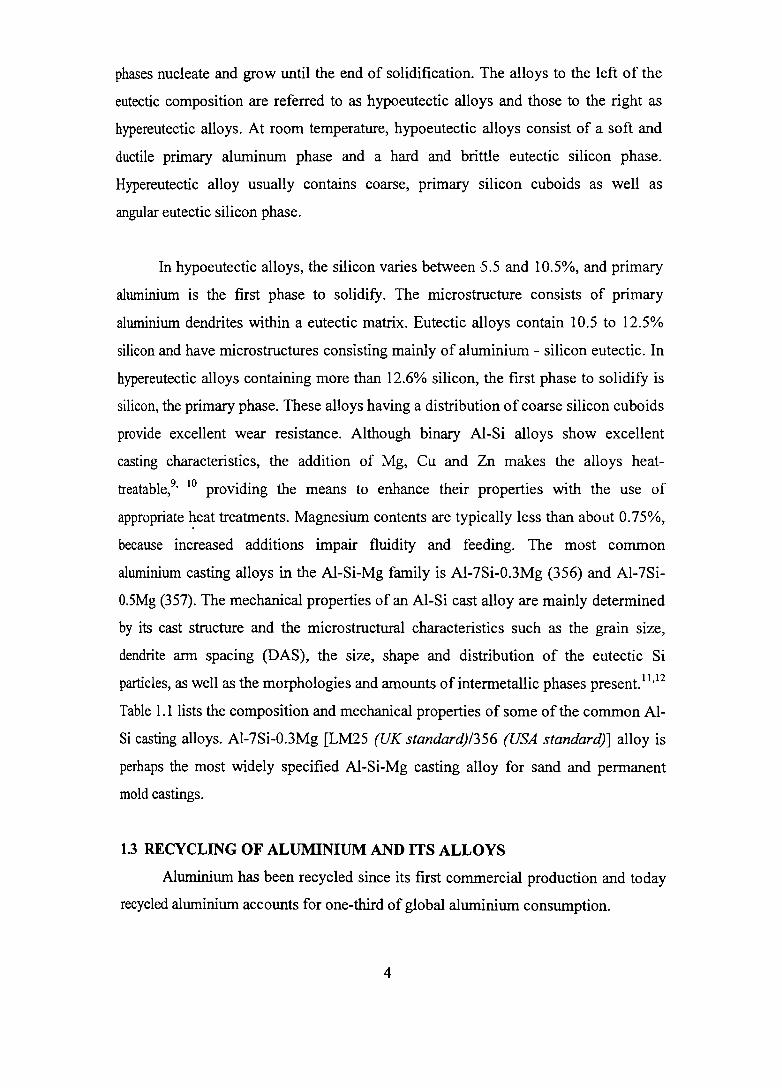
phases nucleate and grow until the end of solidification. The alloys to the left of the
eutectic composition are referred to as hypo eutectic alloys and those to the right as
hypereutectic alloys. At room temperature, hypo eutectic alloys consist of a soft and
ductile primary aluminum phase and a hard . and brittle eutectic silicon phase.
Hypereutectic alloy usually contains coarse, primary silicon cuboids as well as
angular eutectic silicon phase.
In hypoeutectic alloys, the silicon varies between 5.5 and 10.5%, and primary
aluminium is the first phase to solidify. The microstructure consists of primary
aluminium dendrites within a eutectic matrix. Eutectic alloys contain 10.5 to 12.5%
silicon and have microstructures consisting mainly of aluminium - silicon eutectic. In
hypereutectic alloys containing more than 12.6% silicon, the first phase to solidify is
silicon, the primary phase. These alloys having a distribution of coarse silicon cuboids
provide excellent wear resistance. Although binary AI-Si alloys show excellent
casting characteristics, the addition of Mg, eu and Zn makes the alloys heat
treatable,9, 10 providing the means to enhance their properties with the use of
appropriate ~eat treatments. Magnesium contents are typically less than about 0.75%,
because increased additions impair fluidity and feeding. The most common
aluminium casting alloys in the Al-Si-Mg family is AI-7Si-0.3Mg (356) and AI-7Si
O.SMg (357). The mechanical properties of an AI-Si cast alloy are mainly determined
by its cast structure and the microstructural characteristics such as the grain size,
dendrite arm spacing (DAS), the size, shape and distribution of the eutectic Si
particles, as well as the morphologies and amounts of intermetallic phases present. 11,12
Table 1.1 lists the composition and mechanical properties of some of the common AI
Si casting alloys. AI-7Si-0.3Mg [LM25 (UK standard)1356 (USA standard)] alloy is
perhaps the most widely specified Al-Si-Mg casting alloy for sand and permanent
mold castings.
1.3 RECYCLING OF ALUMINIUM AND ITS ALLOYS
Aluminium has been recycled since its first commercial production and today
recycled aluminium accounts for one-third of global aluminium consumption.
4

Tab
le 1
.1:
Com
mon
AI-
Si a
lloys
and
the
ir m
echa
nica
l pr
oper
ties
Mec
hani
cal P
rope
rtie
s
Allo
y C
ompo
siti
on
Ult
imat
e T
ensi
le S
tren
gth
Mod
ulus
E
long
atio
n H
ardn
ess
(MP
a)
(GP
a)
(%)
(BH
N)
356
(T6)
A
l-7S
i-0.
3Mg
300
71
3 10
5 V
I
357
(T6)
A
l-7S
i-0.
57M
g 36
5 71
5
100
319
(T6)
A
l-6.
5Si-
4.5C
u 27
6 71
3
95
413
Al-
12S
i 20
0 71
13
60
A39
0 (T
6)
Al-
17S
i-4.
5Cu
310
71
1 14
5 !
---
--
---
--
--
---
----

Anything made of aluminium can be recycled repeatedly; not only cans, but also
aluminium foil, plates, window frames, garden furniture and automotive components
can be melted down and re-used. Aluminium is a sustainable material, whose
recyclability and applications justify the high energy requirement of primary
aluminium production. The transport sector is forecast to be the most rapidly
expanding end-use sector due to the lightweight and energy saving qualities of the
material. During an automobile's construction a kilogram of aluminium can replace
two kilograms of conventional heavier materials, thus contributing to the reduction of
the vehicle's weight and therefore its fuel consumption. This means that, over the
vehicle's lifetime, every kilogram of aluminium used saves an equivalent of twenty
kilograms of C02. 13 Current estimatesl4 show that globally there will be, by the year
2020, a 35% increase of C02 emissions from all vehicles. An increased use of
aluminium would reduce this increase down to 28% and thus help towards making the
transportation sector more sustainable.
Recently, appeal for recycling of resources is becoming more and more
intensive with increasing public awareness on environmental issues. Climate change
is particularly important to the aluminium industry worldwide because of (i) the
relatively high energy consumption and greenhouse gas emissions associated with the
production of primary aluminium and (ii) the significant potential to reduce
greenhouse gas emissions through increased use of aluminium in transportation
applications and recycled aluminium.
Recycling of aluminium brings potential energy savings of up to 95% and
produces 99% less emission than primary aluminium production from ores. The metal
can also be recycled indefinitely, as reprocessing does not damage its structure. 13
Therefore, secondary aluminium and alloys are getting wide acceptance world-wide.
The efficiency of aluminium recycling translates into high recycling rates for the
various applications. The lightness of aluminium products contributes to fuel savings
and reductions in emissions. Recycling rates for building and transport applications
range from 60-90 per cent in various countries.
6

The aluminium industry is working with the automobile manufacturers to
enable easier dismantling of aluminium components from cars in order to improve the
sorting and recovery of aluminium. During recycling, most of the parts are mixed
together regardless of their chemical composition, as sorting of the parts may not be
commercially viable. Efforts are then made to correct the composition of the resulting
alloy on line. This practice also has economic limitations. Furthermore, certain
elements are either difficult and for expensive to remove (e.g. iron and magnesium).
Iron is always present in commercial aluminium alloys and has consistently emerged
as the main impurity element and perhaps the most detrimental to the mechanical
properties of these alloys. Hence, the increasing use of recycled aluminum casting
alloys raises the necessity for strict process control to remove the ill effects of
impurity elements.
7

CHAPTER 2
LITERATURE REVIEW
2.1 INTRODUCTION
The popularity of AI-Si casting alloys results in a continuing increase in their
demand for components with higher and consistent mechanical properties. 15 AI-7Si
O.3Mg alloy fmds widespread applications in automotive, aerospace and general
engineering industries due to its excellent combination of properties such as good
fluidity, low coefficient of thermal expansion, high strength-to-weight ratio and good
corrosion resistance.5 These foundry alloys possess excellent tensile and fatigue
properties and good corrosion resistance.16
2.2 PARAMETERS INFLUENCING THE STRUCTURE AND PROPERTIES OF AI-Si-Mg CAST ALLOYS
The physical and mechanical properties attainable in these alloys are strongly
influenced by the alloy composition, impurity elements, melt treatments, solidification
characteristics, casting defects, and heat treatment. 5
2.2.1 Alloy Composition
Hypoeutectic alloys in the AI-Si-Mg system containing nominally 7% Si and
about 0.25 to 0.7% Mg have widespread applications especially in the aerospace and
automotive industries.
2.2.1.1 Major alloying elements
Properties of AI are usually enhanced by the addition of major alloying
elements such as eu, Si, Mg, Mn, Zn, Li, Ni, and then subjecting the alloys to various
thermal, mechanical and thermomechanical treatments.
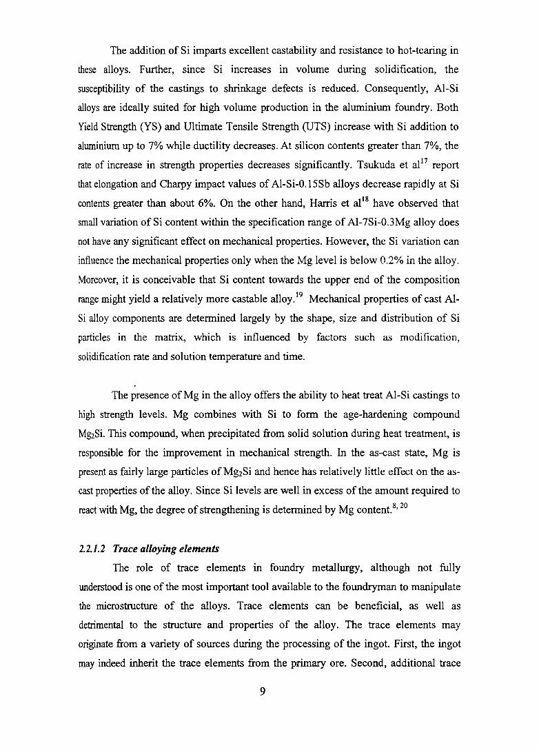
The addition of Si imparts excellent castability and resistance to hot-tearing in
these alloys. Further, since Si increases in volume during solidification, the
susceptibility of the castings to shrinkage defects is reduced. Consequently, AI-Si
alloys are ideally suited for high volume production in the aluminium foundry. Both
Yield Strength (YS) and Ultimate Tensile Strength (UTS) increase with Si addition to
aluminium up to 7% while ductility decreases. At silicon contents greater than 7%, the
rate of increase in strength properties decreases significantly. Tsukuda et al 17 report
that elongation and Charpy impact values of AI-Si-O.lSSb alloys decrease rapidly at Si
contents greater than about 6%. On the other hand, Harris et al l8 have observed that
small variation of Si content within the specification range of AI-7Si-0.3Mg alloy does
not have any significant effect on mechanical properties. However, the Si variation can
influence the mechanical properties only when the Mg level is below 0.2% in the alloy.
Moreover, it is conceivable that Si content towards the upper end of the composition
range might yield a relatively more castable alloy.19 Mechanical properties of cast AI
Si alloy components are determined largely by the shape, size and distribution of Si
particles in the matrix, which is influenced by factors such as modification,
solidification rate and solution temperature and time.
The presence ofMg in the alloy offers the ability to heat treat AI-Si castings to
high strength levels. Mg combines with Si to form the age-hardening compound
M~Si. This compound, when precipitated from solid solution during heat treatment, is
responsible for the improvement in mechanical strength. In the as-cast state, Mg is
present as fairly large particles of Mg2Si and hence has relatively little effect on the as
cast properties of the alloy. Since Si levels are well in excess of the amount required to
react with Mg, the degree of strengthening is determined by Mg content. 8, 20
2.2.1.2 Trace al/oying elements
The role of trace elements ID foundry metallurgy, although not fully
understood is one of the most important tool available to the foundryman to manipulate
the microstructure of the alloys. Trace elements can be beneficial, as well as
detrimental to the structure and properties of the alloy. The trace elements may
originate from a variety of sources during the processing of the ingot. First, the ingot
may indeed inherit the trace elements from the primary ore. Second, additional trace
9

elements may be added to the aluminium in the reduction cell. A third source of trace
elements is pick up from the use of master alloys and fluxes to grain refine, or modify
and cleanse the alloy melt. The fourth source of trace elements would be through the
use of recycled scrap or secondary ingot. The last source of trace elements would be
the intentional addition of an element through fluxes or master alloys?l, 22 These
sources make it extremely difficult to eliminate trace elements in commercial practice.
The principal problem with trace elements is that their effects on the
mechanical properties of the alloy are extremely significant even though only a few
ppm of the element may be present. Most detrimental trace elements are surface active
elements having a very low solubility in the primary aluminium phase. They may
contribute to a change in the mechanical properties through several mechanisms. A
trace element may (i) react with another trace element to form an intermetallic
compound (ii) segregate during solidification to the grain boundaries causing grain
boundary embrittlement (iii) get absorbed onto the surface of the primary crystallites
causing a change in its growth and shape and (iv) react with a beneficial trace element
to form an intermetallic compound removing the beneficial element from its role as a
modifier or grain refiner. 23
Additions of Na, Sr, Ca, Sb, Bi, Be, Mn, Cr, Mo, Co, Ti, B, Rare Earth
elements etc have been found to have profound effect on the castability, structure and
properties of AI-Si cast alloYS.16 Na, Sr, Sb, Ca and RE modify the coarse acicular
morphology of eutectic Si into fine fibrous form thereby improving the mechanical
properties of cast AI-Si alloys?4 Ti, B and Zr lead to grain refinement and result in
improved interdendritic feedability, and reduction of porosity and shrinkage defects.25
Be, Cr, Mn, Co, Sr, Ca and RE change the morphology of platelet iron intermetallic
compound to harmless shapes and hence improve the mechanical properties.26, 27 Sb, Bi
and P, interacting with eutectic Si modifiers such as Na and Sr, coarsening the eutectic
Si and degrading the properties, are to be removed from aluminum cast alloys
containing modifiers.28, 29
Calcium, once considered only as a deleterious element because of its
degrading effect on the properties of aluminum alloys, is now being considered to be a
10

beneficial one in many ways. Calcium, entering the aluminum casting alloys along
with the addition of silicon, and appearing as calcium silicides, calcium phosphides,
and calcium nitrides, which are considered to be harmful, requires removal to levels
below 0.003% (30 ppm) and preferably below 0.001% (10 ppm).30 However, Ca
introduced in the elemental fonn modifies the eutectic silicon in AI-Si alloys/I-38
improves the fracture toughness and impact properties of high iron containing recycled
aluminum alloys,27,39-42 scavenges the effect of Sb from secondary alloys,43,44 imparts
superplastic properties,45-49 and enables production of aluminum foams50-55 and
aluminum metal matrix composites.56-64 AIuminum alloys containing Ca as an
intentional alloying element are applied industrially in the fonn of sacrificial anodes,
bearings, electrolytic capacitor cathode foils, packaging and others.65-86 Based on the
extensive literature collection, compilation and analysis, a review paper on "The Role
of Calcium in Aluminum Based Alloys and Composites,,87 is published in International
Materials Reviews, one among a few high impact factor journal in the area of
Metallurgy and Materials from UK.
2.2.1.3 AI-7Si-0.3Mg alloy
Among the various AI-Si-Mg alloys, the LM25/356 alloy of composition AI-
6.5-7.5Si-0.35-0.45Mg is the most widely used one. This alloy is used for investment,
sand and pennanent mould castings. The designations, physical and mechanical
properties of this alloy are given in Tables 2.1, 2.2 and 2.3 respectively.
2.2.2 Solidification Characteristics
Generally, aluminium alloys solidify by either skin fonning or pasty or mushy
manner. The fonnation of an equiaxed dendritic structure is the nonnal mode of
solidification for commercial AI-Si, AI-Si-Mg and AI-Si-Cu casting alloys. Proper
understanding of the solidification behaviour of the alloy helps in overcoming the
defects arising during solidification particularly the solidification shrinkage. The
secondary dendrite arm spacing (SDAS) is the parameter used to describe the scale of
equiaxed dendritic structures. Castings with fine scale SDAS typically display finer
intermetallics, fmer interdendritic porosity and limited segregation.88, 89 The SDAS is
mainly dependent on solidification rate and temperature gradient. However, it is also
dependent on composition, to a lesser degree.90, 91 It has been observed that addition of
11
Fe to 319 (AI-6.5Si-4Cu) alloy decreases the SDAS. The mechanism proposed to
account for this is that p-AIsFeSi needles increase the nucleation rate of eutectic silicon
and hence minimise dendrite arm coarsening at eutectic temperature.91
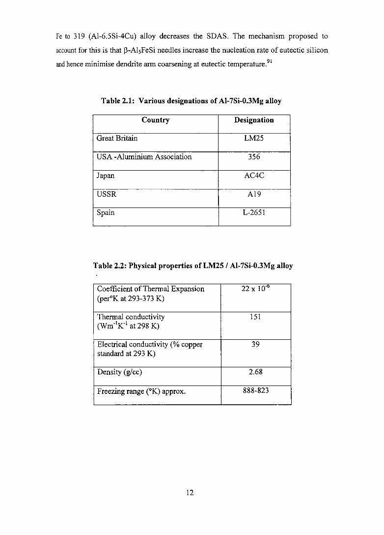
Table 2.1: Various designations of AI-7Si-O.3Mg alloy
Country Designation
Great Britain LM25
USA -Aluminium Association 356
Japan AC4C
USSR A19
Spain L-2651
Table 2.2: Physical properties of LM25 I Al-7Si-O.3Mg alloy
Coefficient of Thermal Expansion 22 x 1O-t> (peroK at 293-373 K)
Thermal conductivity (Wm-1K-1 at 298 K)
151
Electrical conductivity (% copper 39 standard at 293 K)
Density (glee) 2.68
Freezing range (OK) approx. 888-823
12

-w
Tab
le 2
.3:
Mec
hani
cal p
rope
rtie
s o
f LM
2S! A
I-7S
i-O
.3M
g al
loy
Mec
hani
cal
LM
2S-M
L
M2S
-TE
L
M2S
-TB
7 L
M2S
-TF
P
rop
erti
es
San
d
Chi
ll
San
d
Chi
ll
San
d
Chi
ll
San
d
Chi
ll
0.2%
Pro
of
80-1
00
80-1
00
120-
150
130-
200
80-1
10
90-1
10
200-
250
220-
260
Str
ess
(MP
a)
Ten
sile
Str
engt
h 13
0-15
0 16
0-20
0 15
0-18
0 19
0-25
0 16
0 23
0 23
0-28
0 28
0-32
0 (M
Pa)
Elo
ngat
ion
(%)
2 3
1 2
2.5
5 -
2
Bri
nell
55
-65
55-6
5 70
-75
75-9
5 65
-75
65-7
5 90
-110
90
-110
H
ardn
ess
Mod
ulus
of
71
71
71
71
71
71
71
71
Ela
stic
ity
(GP
a)
She
ar S
tren
gth
--
140
--
-18
0 25
0 (M
P a)
--------
--
--
----
'---
-----
------
--
------
M-
As
cast
con
diti
on:
TE
-P
reci
pita
tion
trea
ted
cond
itio
n; T
B7-
solu
tion
trea
ted
and
stab
iliz
ed c
ondi
tion
; T
F -
full
y he
at tr
eate
d co
ndit
ion.

2.2.3 Casting Defects and their Control
Porosity in cast aluminum and its alloys appears mainly in one of the two
forms: (i) the pinhole pores due to the gas evolution and (ii) the shrinkage cavities due
to the improper feeding during solidification. Many process and/or design factors, such
as local thermal conditions,92 feeding capability,93 and applied pressure94 are known to
affect porosity formation. Metal related factors, including dissolved hydrogen,95
inclusions,96,97 modifying elements98,99 and other minor elements additionsloo can also
influence porosity formation. Cao and CampbeUIOI have pointed out the influence of
oxide films folded into the melt during pouring as being conducive to porosity
formation. Neglecting pore formation due to entrapped air, which is a consequence of
bad casting design and practice, the ease of pore formation can be described by the . 102 equatIOn ,
........................ (1)
Where, Pg is the equilibrium pressure of dissolved gases in the liquid,
Ps is the pressure drop due to shrinkage,
P atm. is the pressure of the atmosphere over the system
Ph is the pressure due to the metallostatic head and
Ps-I is the pressure due to surface tension at the pore-liquid interface.
Since the parameters Ph and Patm are constant for a given casting, the dissolved
gas pressure, Pg, is a major driving force in microporosity formation. Shrinkage
porosity pressure, Ps, which is directly related to the ease of interdendritic feeding is
not easy to control. The remaining parameter in equation (1) is P 5-\ , the surface tension
effect. Alloying additions to aluminium may decrease or have virtually no influence on
surface tension. Figure 2.1 shows the effect of alloying elements on the surface tension
of 99.99 Al obtained by the capillary method at 973 to 1013 K in argon atmosphere. It
is seen that Bi, Ca, Li, Mg, Pb, Sb and Sn substantially reduce the surface tension of
99.99 Al, whereas Ag, Cu, Fe, Ge, Mn, Si and Zn have little effect.103 Velasco et al104
have reported that calcium addition exerts a strong influence on reducing the surface
tension in liquid aluminium, and it is expected to have an effect on porosity.
14

E u
880~~--~1~-~1.,--~1.---~1.--~1--'1--~'-1-'1---r-1-'~'-~ ,Germanium. ZinC, silver, Iron, ,ongonese. copper
It rSilicon ,"\.. In
800~~--4---~-+--+-~---PL-+--+--~--r--+~
~·"K~ .
480').... r---Bismut~J' 'i'-t-- r--t--- p
-
Alloying element I er.,.
Figure 2.1: Effect of alloying elements on the surface tension of 99.99 aluminium at 973 to 1013 K in argon atmosphere (Courtesy: Van Horn103 )
15

Dahle et a1 105, 106 have proposed a new theory to understand the porosity
formation in AI-Si alloys, which states that the nucleation and growth characteristics of
the eutectic must be considered for a thorough understanding of porosity formation
because of its 40-100% volume fraction in common casting alloys, and the last
solidifying characteristic/nature. The three different eutectic solidification modes
theoretically expected in AI-Si alloys are (i) nucleation on/adjacent to the primary
phase (ii) independent nucleation in spaces between primary grains and (iii)
solidification opposite to the thermal gradient. The operating mode will control the
distribution of the remaining liquid at the critical high fraction solid stages of
solidification, where feeding is more difficult. The resulting liquid distribution will
determine the size, shape, length and connectivity of the feeding channels.
2.2.3.1 Gas porosity
Hydrogen is the main gas, which is appreciably soluble in aluminium and its
alloys. The presence of dissolved hydrogen in melts of aluminium and aluminium
based alloys is a well known foundry problem. 107, 108 The problem derives from the
difference in the solubility of the hydrogen gas between liquid and solid aluminium.
This leads to ~e rejection of almost all of the dissolved hydrogen on the solidification
of liquid aluminium and the formation of hydrogen bubbles which ultimately cause
porosity in castings and ingots and blisters on sheets and plate.I09-114 Figure 2.2
showing the solubility of hydrogen at one atmospheric pressure in pure aluminium1l5
reveals three distinct characteristics viz.; a low solubility in solid aluminium, a large
change in its solubility at the melting point and a strong temperature dependence in the
liquid state. It has been shown thatl14 for any given alloy and solidification condition,
there is a "threshold hydrogen content" below which no porosity is formed. However,
Fang and Grangerl08 have indicated that there exists some finite pore volume fraction
even at low hydrogen contents. A re-look of the "threshold hydrogen content" has
shown that the threshold values increase with cooling rate. Gas porosity has a negative
effect, not only on mechanical properties but also on machinability and surface
properties of aluminium castings.99, 108, 116-119
16

10 10 -3
1 10 -4
Oi I 0 0 ,... ";It --0 ~ .2- -Cl)
0.1 .0 -5
0.01 10 -6
Temperature (K)
Figure 2.2: The solubility of hydrogen at one atmosphere rsressure in pure aluminium (Courtesy: Gruzleski and Closset1 5)
17

It has been reported that increasing amounts of group lA and HA elements
tend to enhance hydrogen absorption, perhaps because of their tendency for disruption
of the protective oxide skin. The use of eutectic silicon modifiers such as Na, Sr, Ca
and Li has been observed to cause increase in apparent porosity in a variety of AI-Si
based alloy castings.4 It has been observed that porosity and shrinkage in cast AI-Si
alloys are influenced by the fonnation of the intennetallic compounds.8, 120 Some
foundrymen have claimed that Sr contributes to hydrogen pick up, while others have
stated that there is no appreciable gas pick Up.109, 121 Denton and Spittle121 have studied
the effect of Sr (0.04%) addition on the hydrogen absorption by molten LM6 (AI-12Si)
alloy. It has been observed that Sr enhances the susceptibility of the alloys to hydrogen
pick-up, the hydrogen concentration reaching a plateau during a one hour hold period.
Gruzleski et al109 have measured the hydrogen content of non degassed A356 melt at
983 K before and after the addition of 0.03% Sr to the melt for specific periods of time.
No increase in dissolved hydrogen has been found after Sr modification. Baliktay and
Honer38 and Hiroshi and Yoji122 have observed that calcium increases the hydrogen
solubility in aluminium melt as a result of its reaction with moisture in the atmosphere,
and hence is often responsible for the casting porosity.
Fakhman et al123 have noticed increased porosity and gas content with the
presence of small amounts ofNa, Li and Ca. It has also been observed that addition of
calcium has caused significant increase in the casting porosity and an associated
reduction in casting density.124-127 It is a matter of debate whether there is actually an
increase in the absolute level of porosity into a more readily observable fonn. Honer
and Zhang128 have observed that even very low concentrations of Ca give rise to
porosity as a result of higher hydrogen pick-up in G-AISi12 alumimun casting alloy.
The oxidation of Ca changes the composition and morphology of the protective oxide
skin of the melt, which obviously contributes to a faster pick-up of hydrogen in the
melt towards the point of equilibrium.
Velasco et al104 studying the influence of Ca on microporosity in A319 (Al-
6.5Si-4Cu) alloy with Sr modification and titanium refmement have found that the
addition of Ca (above 90 ppm) has resulted in an additive effect on Sr modification and
reduction in the quantity and size of the pores. In Al-Mg alloys containing 2.5,5.0 and
18

10% Mg, it has been reported that calcium addition has reduced the gas content of the
alloys. 129
Investigations on the effect of Ba, Ca, Y and Yb additions on the porosity
formation based on their impact on the eutectic solidification mode have shown that
these elements increase the porosity level with increasing amount compared to the
untreated alloy. However, increasing Ca content reduces and disperses hot tearing as
well as causes the eutectic to evolve from the surface of the casting towards the centre
of the hot spot resulting in concentrated porosity closer to the hot SpOt. 130 Tatur test
results for AI-11.4Si alloy have shown more dispersed shrinkage porosity with
0.0064% (64 ppm) calcium addition compared to more localized ones in the last
solidification area with calcium-free alloy.13I It is obvious from the foregoing that no
consensus exists among the researchers regarding the increase in hydrogen absorption
tendency by aluminum melt containing modifiers.
2.2.3.2 Shrinkage porosity
Shrinkage porosity occurs in regions within the casting, which solidify last,
particularly where isolated liquid pools become cut off from feed liquid by either fully
solidified metal or partially solidified impermeable dendritic networks. Contraction
during solidification leads to micro shrinkage particularly in interdendritic areas. Both
gas and micro shrinkage porosities occur often simultaneously.4 Calcium concentrations
between 0.05-0.1 % (500 - 1000 ppm) have increased both gas porosity and shrinkage
porosity of the AL2 [Al-12Si-0.6Cu] alloy as well as the tendency of eutectic alloys in
fonning shrinkage cracks. 132 Holecek133 has found that the hot tearing tendency is little
affected by calcium content in AI-Si alloys, but its effect on shrinkage cavity formation
is considerable. However, calcium content above 0.003% (30 pp m) has unfavourably
influenced the dissipation of internal shrinkage during solidification of an aluminium
alloy containing 12-13% SL134 On the other hand, the work of Abdollahi and
Gruzleskil35 on Ca addition to A357 alloy reveals no significant increase in melt
hydrogen but increased microporosity with a corresponding decrease in macroporosity.
This is in agreement with the work ofDahle et alIOS, 106 and Knuutinen et al. 130
19
Iron is known to cause porosity and shrinkage defects in AI-Si based casting
alloYS.I36 It has been suggested137-140 that the intermetallic phase Jl-AIsFeSi is the
primary cause of this porosity. The restricted feeding theory suggests that Jl platelets
interfere with liquid feeding, whereas the "pore nucleation theory" suggests that the
~- platelets are active sites for pore nucleation. In AI-Si based foundry alloys, Rooyl41,
142 claims that increase in Fe content leads to reductions in fluidity, poorer feeding
characteristics and increased shrinkage cavity formation. Iwahori et al138 have noted
that in a AC2B alloy, increased Fe levels have led to increased shrinkage porosity.
Anantha Narayanan et al143 have confIrmed a similar trend between iron level and
shrinkage porosity in 319 alloy. Eklund,139 comparing primary and secondary alloys of
various AI-Si compositions, also claims that porosity has been observed to increase as
the proportion of Fe containing phases increases in these alloys.
2.2.4 Melt Treatments
Three melt treatment processes commonly employed in the production of
aluminium castings to control the porosity level and the microstructure and hence
enhance the mechanical properties are degassing modifIcation and grain refInement.
2.2.4.1 Degassing
Virtually gas porosity observed in aluminium castings is attributable to
hydrogen. The solubility limit of hydrogen in molten aluminium is 0.68mll100g about
20 times greater than that in solid aluminium (0.037rnl/100g) at the melting point. As
solidification progresses, hydrogen is rejected at the solid-liquid interface forming
hydrogen gas bubbles. If these bubbles cannot escape, porosity will be present in the
solidified casting. Since the precipitation of hydrogen during the solidifIcation process
is inevitable, the only effective means to limit gas porosity is to reduce the hydrogen
content of the molten metal", l , 144 Reduction of hydrogen level is extremely important
for critical component castings. In order to obtain sound castings with a minimum of
porosity, it is necessary to decrease the hydrogen levels in the order of 0.1 Omll1 00 g of
aluminium before casting. The use and the mode of degassing will depend on the level
of hydrogen desired. Among the many methods in use to reduce hydrogen levels, the
most c~mmon methods are natural de gassing, gas purging, vacuum degassing and
treatment with a flux/tablet. Inert gases or mixtures of inert gases and reactive gases are
20

injected via a lance usually made of graphite or silicon carbide. Various lance designs
including open-end, perforated end and porous plug head are available to achieve
degassing. Recently, lances with rotary impellers or spinning heads have increased the
degassing efficiency by a factor of 5 to 10.
2.2.4.2 Modification
In the AI-Si system, silicon is a non-metal with directed covalent bonds;
therefore, it tends to grow anisotropically into faceted crystals and hence requires more
undercooling for its growth than the isotropic aluminium phase. Consequently, the
coupled region in the AI-Si system is asymmetric. 145 The morphology of eutectic
silicon is the predominant factor determining the mechanical properties. The silicon
particles in the aluminium rich matrix generally grow in the form of coarse platelets
and act as crack initiation sites because of their stress concentration effectl46, 147
resulting in poor mechanical properties. When Si freezes out from an AI-Si melt, it
grows as flakes with atomically flat, (111 )Si-oriented surfaces. These flakes grow by
nucleation of mono-atomic ledges on the (111) surfaces, which subsequently migrate
rapidly over the surface by incorporating further atoms at the ledge. This common
growth process via ledge migration is schematic ally shown in Figure 2.3.
In silicon, twins form readily across the (111) planes and this has the effect of
producing a self-perpetuating groove of 141 degrees at the solid liquid interface. In the
growth of Si flakes from an AI-Si melt, however, the growth takes place near the
thermodynamic equilibrium. Therefore, the density of these planar defects is usually
rather low. Consequently, the flakes cannot "branch," which results in a microstructure
in which the Si particles are large plates.
The process of changing morphology of platelet/acicular Si to a fine fibrous
fonn is known as modification, which results in considerable improvement in the
mechanical properties. The modification of the eutectic Si can be achieved through
rapid rates of solidification and by the addition of modifying agents (modifiers) to the
melt. Full modification is difficult to achieve by only increasing the solidification
cooling rate of the casting, which has varying section thickness and hence different
cooling rates. It is therefore essential to modify the eutectic structure by introducing
21

modifying agents. One possible explanation for the modification is that when a
modifying element of correct atomic size (Figure 2.4) with respect to Si (rmodifier: rsilicon
= 1.646) is incorporated into the melt, the accumulation of such atoms in sufficient
density by adsorption at the liquid-solid growth front poisons the growth of silicon in a
particular direction (Figure 2.5). This phenomenon has been named impurity-induced
twinning and is supported by the observation that the modifier becomes concentrated in
the Si and not in the aluminium phase. It has been observed that modified fibres
contain orders of magnitude more twins than do unmodified Si plates and that the
surface of the fibres is microfacted and rough as a consequence of the intersection of ,
myriads of twin planes with it. Si fibres are crystallographically imperfect and each
surface imperfection is a potential site for branching to occur. As a result, fibres in the
chemically modified eutectic are able to bend, curve and split to create a fine
microstructure; the platelets of the unmodified structure are inhibited by their relative
crystallographic perfection and can do little except forming in a coarse acicular
fashion.24,115
(1 1 1) (1 1 2)
(1 1 1) • Growth Direction
Liquid
Aluminium
Figure 2.3: Ledge migration mechanism responsible for the growth of Si flakes bounded by atomically flat (111) surfaces
22

IICS 2.5 - I Rb
~ -! 1.5- Li
~ u Si
AI
i 1.0-
<
0.5-
~.04-~'--~IUr~+--'--'I--'-~~I~--'-I~~~~~~--T-~ o 10 20 30 40 50 60 70 80
Atomic number
Figure 2.4: Plot of atomic radii vs atomic number, with range of radii which includes elements capable of producing silicon modification - shaded
GROWT H. 'DIRECTAON
L ...... "' ..
Figure 2.5: Schematic representation of impurity atoms pinning the steps of a silicon crystal growing by the layer growth mechanism at the solid/liquid interface24
23

Although the group IA and HA elements of the periodic table, rare earths (La,
Ce or mischmetal), As, Sb, Se, and Cd have been reported to modify the AI-Si eutectic,
only Na and Sr find extensive commercial application.148.155 The works of Hogan and
Shamsuzzohal56, 157 and Lu and Hellawell24 have shown the importance of twinning in
the growth of silicon and that modified silicon contains more twins and has a rough
micro faceted surface. They have shown that impurity atoms of the appropriate size can
force the nucleation of twins and stacking faults at the solid-liquid (Si-metal)
interface. These twins create sites for atom attachment at the interface, encouraging
growth in a manner similar to that of an atomically rough interface. As a consequence,
the morphology of the Si particles changes from flakes to fibers. The primary Al
dendrites do not exhibit shape modification.
It has been concluded that the nucleation of the silicon controls the
solidification of the eutectic, whose subsequent growth is led by silicon having the
smallest constitutional undercooling. However, today, the change in growth
mechanism has been accepted as the reason for Si morphology change with the
addition of modifiers. Several studies l05. 158-160 have recently shown that widely
different eutectic solidification modes can occur in hypoeutectic AI-Si alloys as a result
of the addition of modifying elements. The three different eutectic solidification modes
theoretically expected in AI-Si alloys are (i) nucleation on/adjacent to the primary
phase (ii) independent nucleation in spaces between primary grains and (iii)
solidification opposite to the thermal gradient. The operating mode will control the
distribution of the remaining liquid at the critical high fraction solid stage of
solidification, where feeding is more difficult. The resulting liquid distribution will
determine the size, shape, length and connectivity of the feeding channels. Moreover, it
has been found that it is possible for all these mechanisms to occur in AI-Si alloys,
either independently or combined, based on the alloy and presence of certain elements,
namely Na, Sr, Ca and their levels. A comparison of some characteristics of different
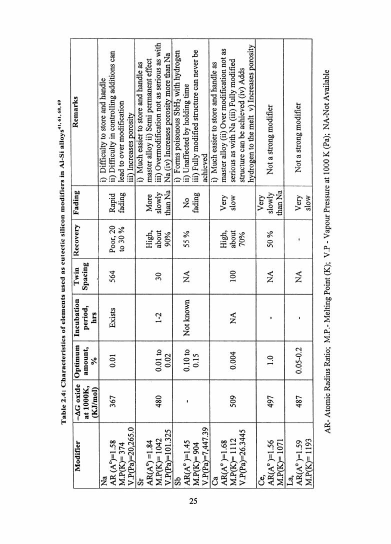
modifiers25, 115, 161,162 is given in the Tab1e' 2.4.
24
IV
V\
Tab
le 2
.4:
Ch
ara
cte
rist
ics
of
ele
men
ts u
sed
as
eu
tecti
c s
ilic
on
mo
dif
iers
in
AI-
Si
allo
ys41
, 61,
68,
69
Mo
dif
ier
-4G
ox
ide
Op
tim
um
In
cub
atio
n
Tw
in
Rec
ov
ery
F
adin
g
Rem
ark
s at
lOO
OK
, am
ou
nt,
p
erio
d,
Sp
acin
g
(KJ/
mo
l)
%
hrs
N
a i)
D
iffi
cult
y to
sto
re a
nd h
andl
e A
R (A
O)=
1.58
36
7 0.
01
Exi
sts
564
Poo
r, 2
0 R
apid
ii
) D
iffi
cult
y in
con
trol
ling
add
itio
ns c
an
M.P
(K)=
374
to
30
%
fadi
ng
lead
to o
ver
mod
ific
atio
n V
.P(P
a)=
20,2
65.0
ii
i) I
ncre
ases
por
osit
y S
r i)
Muc
h ea
sier
to s
tore
and
han
dle
as
AR(A~=1.84
Hig
h,
Mor
e m
aste
r al
loy
ii) S
emi p
erm
anen
t eff
ect
M.P
(K)=
104
2 48
0 0.
01 t
o 1-
2 30
ab
out
slow
ly
iii)
Ove
rmod
ific
atio
n no
t as
seri
ous
as w
ith
V .P
(Pa)
= 1 0
1.3
25
0.02
90
%
than
Na
Na
(iv)
Inc
reas
es p
oros
ity
mor
e th
an N
a S
b i)
F
orm
s po
ison
ous
SbH
2 w
ith
hydr
ogen
A
R(A
O )
=1.
45
-0.
10 to
N
ot k
now
n N
A
55 %
N
o ii)
Una
ffec
ted
by h
oldi
ng ti
me
M.P
(K)=
904
0.15
fa
ding
ii
i) F
ully
mod
ifie
d st
ruct
ure
can
neve
r be
V
.P(P
a)=
7,44
7.39
ac
hiev
ed
Ca
i)
Muc
h ea
sier
to s
tore
and
han
dle
as
AR
(AO
)=
1.68
H
igh,
V
ery
mas
ter
allo
y (i
i) O
ver
mod
ific
atio
n no
t as
M.P
(K)=
111
2 50
9 0.
004
NA
10
0 ab
out
slow
se
riou
s as
wit
h N
a (i
ii)
Ful
ly m
odif
ied
V.P
(pa)
=26
.344
5 70
%
stru
ctur
e ca
n be
ach
ieve
d (i
v) A
dds
hydr
ogen
to t
he m
elt
v) I
ncre
ases
por
osit
y C
e,
Ver
y A
R(A
O )
=1.
56
497
1.0
-N
A
50
%
slow
ly
Not
a s
tron
g m
odif
ier
I M
.P(K
)= 1
071
than
Na
La,
A
R(A
O )
=1.
59
487
0.05
-0.2
-
NA
-
Ver
y N
ot a
str
ong
mod
ifie
r M
.P(K
)= 1
193
slow
AR
-A
tom
ic R
adiu
s R
atio
; M
.P.-
Mel
ting
Poi
nt (
K);
V
.P -
Vap
our
Pre
ssur
e at
100
0 K
(Pa
); N
A-N
ot A
vail
able
Although modification of the eutectic silicon in AI-Si alloys is conunercially
perfonned by Na and Sr addition, calcium also influences modification and is well
recognized as a modifier. Several authors reporting the modification of AI-Si alloys by
calcium have found that its effect persists through remelting.5, 31-38 It has been reported
that the calcium modified eutectic structure of -an SAE332 alloy (AI-9.5Si-3.0Cu
I.OMg) is maintained for about 13 hours at 938.6 K while the sodium modified eutectic
structure is sustained only for about 3-4 hours. 163 Since the radius ratio for Ca is 1.68,
which is close to the needed ratio of 1.646 for modification, Ca also modifies the
eutectic silicon. Gokhshtein and Vasil'eva;64 studying the mechanism of modification
of silumins (AI-Si alloys) by Ca, Na and other elements, have found that the principal
influence of Ca is to deactivate the impurity particles, which in unmodified silumin act
as crystallization centres for eutectic Si. This is in line with the work ofBelov et a1. 165
The eutectic solidification mode in A356.0 (AI-7Si-0.37Mg) alloy modified
with Ba, Ca, Y and Yb additions has been determined by comparing the
crystallographic orientation of the aluminium in the eutectic to the surrounding primary
aluminium dendrites. It has been shown that each of the elements added promotes
heterogeneous nucleation of eutectic grains in the interdendritic liquid, while the
aluminium in the unmodified alloy grows epitaxially from the dendrites. Furthermore,
Ca and Y have resulted in a strong dependency of eutectic solidification on the thermal
gradient, i.e, the eutectic evolves from the walls towards the centre of the sample on a
macro-scale.166
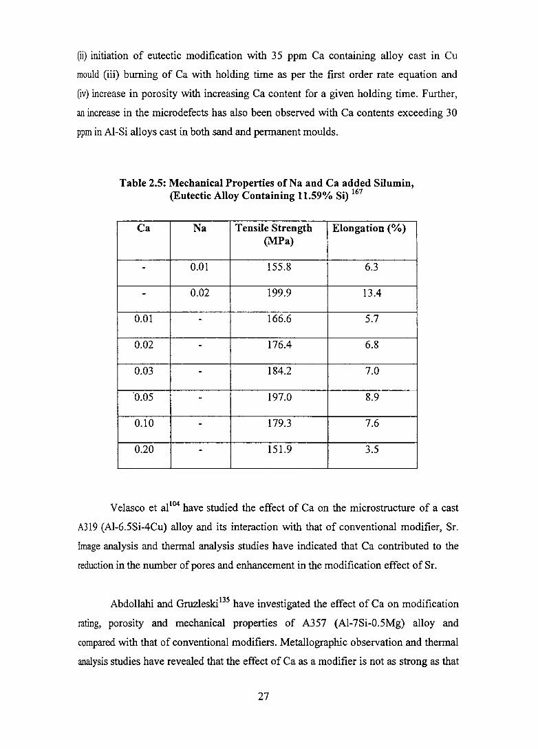
Tsumura167 has found that addition of 0.05% (500 ppm) Ca modifies a eutectic
AI-Si alloy (AI-l1.59Si-0.21Fe-0.OlCu-0.006Na-0.009Ti) and results in maximum
tensile strength and elongation [Table 2.5]. While the tensile strength is almost the
same as the eutectic alloy modified with 0.02% Na, elongation is significantly (50%)
lower. Further increase in calcium addition has resulted in decreased properties owing
to the formation of CaSh.
Baliktay and Honet8 studying the effect of calcium on eutectic modification
and porosity formation in G-AISil0Mg alloy have observed (i) reduction of ~ 4° K in
eutectic temperature with 150 ppm Ca containing alloy cast in graphite mould
26
(ii) initiation of eutectic modification with 35 ppm Ca containing alloy cast in Cu
mould (iii) burning of Ca with holding time as per the first order rate equation and
(iv) increase in porosity with increasing Ca content for a given holding time. Further,
an increase in the microdefects has also been observed with Ca contents exceeding 30
ppm in AI-Si alloys cast in both sand and permanent moulds.
Table 2.5: Mechanical Properties ofNa and Ca added Silumin, (Eutectic Alloy Containing 11.59% Si) 167
Ca Na Tensile Strength Elongation (0/0) (MPa)
- 0.01 155.8 6.3
- 0.02 199.9 13.4
0.01 - 166.6 5.7
0.02 - 176.4 6.8
0.03 - 184.2 7.0
·0.05 - 197.0 8.9
0.10 - 179.3 7.6
0.20 - 151.9 3.5
Ve1asco et al104 have studied the effect of Ca on the microstructure of a cast
A319 (AI-6.5Si-4Cu) alloy and its interaction with that of conventional modifier, Sr.
Image analysis and thermal analysis studies have indicated that Ca contributed to the
reduction in the number of pores and enhancement in the modification effect of Sr.
Abdollahi and Gruzleski I35 have investigated the effect of Ca on modification
rating, porosity and mechanical properties of A357 (AI-7Si-0.5Mg) alloy and
compared with that of conventional modifiers. Metallographic observation and thermal
analysis studies have revealed that the effect of Ca as a modifier is not as strong as that
27

of Na or Sr at low cooling rates but a fully modified structure is obtained at high
cooling rates. Contrary to the results of Baliktay and Honer,38 the above authors have
observed that the recovery of Ca in the melt is high and does not fade with long
holding times. Figure 2.6 presents the average microporosity and pipe volume
(measure of macroporosity) in modified and unmodified Tatur samples. It is seen that
modification treatment with either Sr or Ca increases microporosity, but the increase is
greater in the case of calcium. However, modification decreases the pipe volume, with
a greater decrease in the case of Ca than Sr. Further, Ca modification improves the
mechanical properties especially elongation.
Sasaki and Yamadal68 have invented an AI-Si alloy having fine silicon crystals
evenly distributed throughout the whole thickness of the casting with excellent
mechanical characteristics and significantly reduced surface porosity. This alloy has
been pressure cast after modifying with a flux containing at least one element selected
from the group ofNa, Sb, Sr, and lor Ca.
12 12 - M icroporosity 10 .6
10 ~ M acroporosity 10
- 3! .§. 8 8 " 3:
CD III n
~ < .. 2- 0
·in " 0 c: 0 ... 6 6 3 .. 0 _CD
0 Co 1/1 0 3 ~ ... u ~ -
4 4
2 2
o 0 Not Modified Sr Modified Ca modified
M odlflcation conditions
Figure 2.6: Microporosity and macroporosity in modified and unmodified A357 alloy
28
Knuutinen et al169 investigating the modifying action of Ba, Ca, Y and Yb in
Al-7Si-O.3Mg alloy have found that Ca modifies the eutectic silicon to fine, fibrous Si
structure and the modification level increases with increasing level of Ca. Thennal
analysis study has shown that with Ca addition (36 ppm), the eutectic arrest changes
dramatically and further increase in Ca concentration has only a minor impact on the
eutectic arrest in tenns of nucleation temperature, growth temperature and
recalescence.
2.2.4.3 Grain refinement
Grain refmement refers to the development of an increased number of sites for
the nucleation of the primary alpha aluminium phase during casting solidification. Two
recent reviews on grain refinement of Al and its alloys published in 2002 and 2003 by
Murty et af5 and Greer et al170 respectively are available for reference. McCartney171
has defmed grain refinement as the deliberate suppression of columnar grain growth in
ingots and castings and fonnation of fine equiaxed solidification structure throughout
the material. Grain size in metals and alloys influences the properties. An equiaxed
grain structure ensures unifonn mechanical properties, reduced hot tearing, improved
feeding to eliminate shrinkage porosity, even distribution of second phases and
rnicroporosity on a fine scale as well as improved machinability in castings. Among the
various methods to refme the grain, treating the melt with Al-Ti and AI-Ti-B master
alloys providing large quantities of boride and aluminide nuclei into the molten metal
is known to be effective. An effective grain refmer should:25
(i) have a melting point higher than the alloy being solidified
(ii) be able to initiate freezing at very small undercooling
(iii) have a sufficient number of nucleating particles unifonnly distributed
(iv) have larger size nucleating particles than a critical size depending on the
undercooling of the melt.
The mechanism of grain refinement in aluminium after the addition of Al-Ti-B
master alloys is still a subject of controversy. Several mechanisms have been
postulated and are reviewed elsewhere.25 According to Jones and Pearson,172 a grain
refiner is effective if the grain size of aluminium falls below an acceptance level (220
j.lIIl). It has been found that grain refinement of 356 (Al-7Si-0.3 Mg) alloy with
29

AI-sri-IB master alloy leads to fine dendrite arm spacing of the solidified structure
(Figure 2.7).173 The alloying elements as well as the impurities present in the
alwniniwn alloys play significant roles in deciding their grain refining behaviour.
While a large number of alloying elements and some impurities (Ca, Be, Mg, Sr, Bi, In,
Pb, Sb, Sn and Co) in the alwniniwn alloys enhance their grain refining capabilities,
elements such as Cr, Si, Zr, Li lead to poisoning when alwniniwn is grain refined by
the conventional addition ofO.01%Ti of the AI-STi-1B master alloy. However, master
alloys such as AI-B and boron rich AI-Ti-B appear to have better grain refining
capability in the case of aluminiwn alloys containing poisoning elements?5
It has been reported that calciwn enhances the gram refining action of
titanium. 174 Abdel-Rahim et al i75 have observed that the grain refinement of aluminium
by titaniwn is enhanced by additional alloying with < 0.1 % Be, Sr, Ca or Mg in the
form of respective master alloys. The increase in the seed crystal formation rate in the
presence of alkaline earth metals is due to the isomorphic growth of ternary or
quaternary phases on Ai) Ti.
2.2.5 Effect of Alloying Elements on the Castability of Aluminium Alloys
Castability is the ability of an alloy to effectively fill a mould and form a
dimensionally accurate casting of acceptable soundness and integrity. It refers
principally to two measurable foundry parameters: molten alloy fluidity and the casting
soundness as measured by the type and distribution of solidification shrinkage.
Calcium is expected to affect the casting characteristics of alwniniwn casting alloys
because of its significant influence on the viscosity and surface tension of the melt. 176
2.2.5.1 Formation of oxides and their effects
Alwniniwn readily oxidizes in the presence of air or moisture rapidly forming
a strong, thin impermeable film of protective oxide on any exposed metal surface. Most
of the group lA and IIA elements also readily form very stable oxides. These oxides
have lower densities than the corresponding parent metal and so tend to be broken and
porous to both air and moisture (BeO is an exception). Fox and Nilmanil77 have used
the Pilling - Bedworth (PB) ratio (oxide density to metal density) to explain this
tendency. Elements with PB ratios < 1 form discontinuous and non-protective oxides,
30

while those with PB ratios > 1 fonn continuous and protective oxides. PB ratios of
BeO, MgO, CaO, a-Ah03 and y-Ah03 are 1.68, 0.78, 0.65, 1.28 and 1.45
respectively. Thus, the melt containing Ca and Mg cannot maintain its continuous
protective Ah03 skin even when the melt is quiescent. Instead, it will be subjected to a
rapid and continuous oxidation leading to fonnation of more oxides. These oxides
appear to play a major role in providing nucleation sites for porosity. Further, entrained
oxides lead to increased melt viscosity and hence reduced fluidity and poor feeding of
castings. Figure 2.8 shows the comparative oxidation losses caused by the addition of
various elements to aluminium melt and it should be noted that the group lA and HA
elements (Na, Ca and Mg) have a considerable oxidation loss than the very little of
silicon.
A strong oxide will protect the metal from further reactions with the
environment (good aspect) and may prevent the liquid from flowing into intricate parts
of the mould (bad aspect) but staying on the surface of the advancing metal front, so
that its final location can be controlled (good aspect). On the other hand, a weak
oxide in a turbulent flow will break up and get incorporated in the bulk of the casting in
the form of in~lusions (bad aspect).178
2.2.5.2 Fluidity
Fluidity describes the ability of a metal to fill a mould completely. Campbell94
defines fluidity as ''the maximum distance to which the metal will flow in a standard
mould". It is a complex characteristic influenced by surface tension, viscosity, alloy
freezing range, melt cleanliness, superheat and solidification conditions. For good
castability, fluidity needs to be sufficient but not so excessive as to cause mould
penetration or flashing along parting lines. There are two groups of variables that affect
the fluidity: 1) alloy parameters and 2) mould parameters. The effect of chemical
modifiers on casting fluidity has been investigated by a number of researchers.
Venkateswaran et al,179 in an extensive study using the vacuum suction technique on
eutectic AI-Si alloy, have concluded that both Na and Sr additions, individually or in
combination, with or without accompanying Ti-based grain refiner, have resulted In
reduction in casting fluidity. However, additions of either Sb, or Sb plus Ti have
31
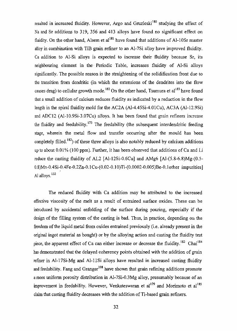
resulted in increased fluidity. However, Argo and Gruzleski l80 studying the effect of
Na and Sr additions to 319, 356 and 413 alloys have found no significant effect on
fluidity. On the other hand, Alsem et al l81 have found that additions of Al-l OSr master
alloy in combination with TiB grain refiner to an AI-7Si alloy have improved fluidity.
Ca addition to AI-Si alloys is expected to increase their fluidity because Sr, its
neighbouring element in the Periodic Table, increases fluidity of AI-Si alloys
significantly. The possible reason is the straightening of the solidification front due to
the transition from dendritic (in which the extensions of the dendrites into the flow
causes drag) to cellular growth mode.182 On the other hand, Tsumura et al 183 have found
that a small addition of calcium reduces fluidity as indicated by a reduction in the flow
length in the spiral fluidity mold for the AC2A (Al-4.45Si-4.01Cu), AC3A (AI-12.9Si)
and ADC12 (Al-1O.9Si-3.07Cu) alloys. It has been found that grain refiners increase
the fluidity and feedability.173 The feedability (the subsequent interdendritic feeding
stage, wherein the metal flow and transfer occurring after the mould has been
completely filled. 182) of these three alloys is also notably reduced by calcium additions
up to about 0.01% (100 ppm). Further, it has been observed that additions of Ca and Li
reduce the casting fluidity of AL2 [AI-12Si-0.6Cu] and AMg6 [Al-(S.8-6.8)Mg-(0.S
O.8)Mn-OASi-0.4Fe-0.2Zn-0.1 Cu-(0.02-0.1 0)Ti-(0.0002-0.005)Be-0.1 other impurities]
AI alloys. 132
The reduced fluidity with Ca addition may be attributed to the increased
effective viscosity of the melt as a result of entrained surface oxides. These can be
introduced by accidental enfolding of the surface during pouring, especially if the
design of the filling system of the casting is bad. Thus, in practice, depending on the
freedom of the liquid metal from oxides entrained previously (i.e. already present in the
original ingot material as bOUght) or by the alloying action and casting the fluidity test
piece, the apparent effect of Ca can either increase or decrease the fluidity.182 Chai l84
has demonstrated that the delayed coherency points obtained with the addition of grain
refmer in AI-17Si-Mg and AI-I 1 Si alloys have resulted in increased casting fluidity
and feedability. Fang and Granger108 have shown that grain refining additions promote
a more unifonn porosity distribution in AI-7Si-0.3Mg alloy, presumably because of an
improvement in feedability. However, Venkateswaran et al179 and Morimoto et al185
claim that casting fluidity decreases with the addition of Ti-based grain refiners.
32

Figure 2.7: Microstructure of AI-Si-Mg (356) alloy after grain refining with AI-5Ti-lB master alloy (Courtesy: Kashyap and Chandrashekarl73)
v: v: 0
.....l c:: 0 ...... C":I
"'0 .-x 0
o j tr'T J
20 40 60
Nu
Ca
Si Pure Al
........ ~ ............. ./ I I I
80 100 120 140
Time (hrs)
Figure 2.8: Comparative oxidation losses caused by the addition of various elements to aluminium melt (Courtesy: Fox and Nilmani177)
33

2.2.6 Heat Treatment
Cast AI-Si-Mg alloys can be heat treated to obtain an optimum combination of
strength and ductility. The heat treatment consists of solutionizing at temperatures
close to eutectic temperature, quenching and a combination of natural and artificial
aging. The enhancement in tensile properties after the thermal treatment has largely
been attributed to the formation of non-equilibrium precipitates of M~Si within the
primary dendrites during aging and the changes occurring in Si particle characteristics
from the solution treatment. The properties attainable in the casting are determined by
the temperature and the duration of both solutionizing and aging processes. 186
2.2.6.1 Temper selection
Several heat treatment tempers such as T4, T5, T6 and T7 have been
developed for AI-Si-Mg alloys. Fully heat treated structures such as T6 produce higher
strengths because of the formation of greater amounts of fine M~Si precipitates during
aging. At low Mg contents and low aging times, ductility obtained with a T6 treatment
is greater than in a T7 temper. The T7 temper exhibits high ductility with minimum
internal stresses in the casting. Compared to Tl (as-cast) condition, the yield strength
for a T7 temper is greatly enhanced without any loss in ductility. The response of the
casting to a T5 treatment is determined primarily by the cooling rates, (as in small
permanent mould castings) with some Mg retained in solid solution precipitating as
M~Si during aging. This temper may be an economic proposition in modified alloys
when moderate strengths are required. The T6 (in some cases T7) treatment gives the
optimum balance of strength and ductility and is most commonly employed with
aluminium alloy castings. 161, 186
2.2.6.2 Solution heat treatment
The solution treatment of the casting produces the following effects:
• Dissolves Mg2Si particles
• Homogenizes the casting
• Changes the morphology of eutectic Si
Heat treatable aluminium alloys display appreciable solid solubility of the
precipitating M~Si phase at the solidus temperature. Under equilibrium conditions,
34

solubility decreases with temperature and the second phase precipitates out as coarse
particles. This decrease in solubility is a prerequisite to a significant response to heat
treatment. In order to obtain a maximum concentration of Mg and Si particles in solid
solution, the solution temperature should be as close as possible to the eutectic
temperature. In most cases, the AI-7Si-0.3Mg (356) and AI-7Si-0.5Mg (357) type
alloys are solutionized at 813 ± 5 K. At this temperature, about 0.6% Mg can be placed
in solution (Figure 2.9).
The solution treatment homogenizes the cast structure and mlmmlzes
segregation of alloying elements in the casting. The segregation of solute elements
resulting from dendritic solidification may have an adverse effect on mechanical
properties. The time required for homogenization is determined by the solution
temperature and dendrite arm spacing. In the case of AI-Si-Mg casting alloys, there is
no strong segregation of Mg and Si. 186 Closset et al l87 have found that homogenization
was essentially complete within 30 min at 823K. No difference in the rate of
homogenization between modified and unmodified samples has been observed.
Temperature (F) 570 660 750 840 930 1020 1110
1.0 1.4
1.2 0.8
E 1.0
~.
0.6 c 'iii 0.8 0 CD .2 c Cl en «I :E. 0.4 0.6 ~
'f1. 0.4
0.2 0.2
0.0 0.0 300 350 400 450 500 550 600
Temperature (C)
Figure 2.9: Equilibrium solubility of Mg and Si in solid aluminium when both M~Si and Si are present186
35
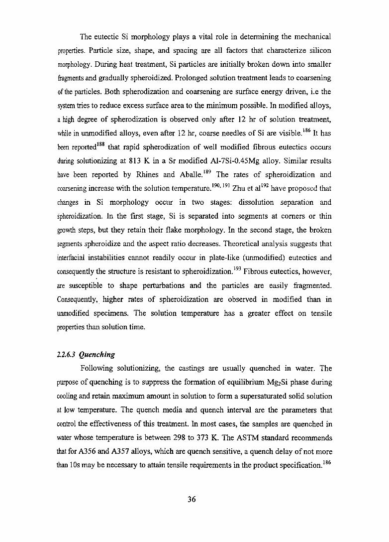
The eutectic Si morphology plays a vital role in determining the mechanical
properties. Particle size, shape, and spacing are all factors that characterize silicon
morphology. During heat treatment, Si particles are initially broken down into smaller
fragments and gradually spheroidized. Prolonged solution treatment leads to coarsening
of the particles. Both spherodization and coarsening are surface energy driven, i.e the
system tries to reduce excess surface area to the minimum possible. In modified alloys,
a high degree of spherodization is observed only after 12 hr of solution treatment,
while in unmodified alloys, even after 12 hr, coarse needles of Si are visible. 186 It has
been reportedl88 that rapid spherodization of well modified fibrous eutectics occurs
during solutionizing at 813 K in a Sr modified Al-7Si-0.45Mg alloy. Similar results
have been reported by Rhines and Aballe. 189 The rates of spheroidization and
coarsening increase with the solution temperature. 190, 191 Zhu et al192 have proposed that
changes in Si morphology occur in two stages: dissolution separation and
spheroidization. In the first stage, Si is separated into segments at corners or thin
growth steps, but they retain their flake morphology. In the second stage, the broken
segments spheroidize and the aspect ratio decreases. Theoretical analysis suggests that
interfacial instabilities cannot readily occur in plate-like (unmodified) eutectics and
consequently the structure is resistant to spheroidization. 193 Fibrous eutectics, however,
are susceptible to shape perturbations and the particles are easily fragmented.
Consequently, higher rates of spheroidization are observed in modified than in
unmodified specimens. The solution temperature has a greater effect on tensile
properties than solution time.
2.2.6.3 Quenching
Following solutionizing, the castings are usually quenched in water. The
purpose of quenching is to suppress the formation of equilibrium Mg2Si phase during
cooling and retain maximum amount in solution to form a supersaturated solid solution
at low temperature. The quench media and quench interval are the parameters that
control the effectiveness of this treatment. In most cases, the samples are quenched in
water whose temperature is between 298 to 373 K. The ASTM standard recommends
that for A356 and A357 alloys, which are quench sensitive, a quench delay of not more
than 10s may be necessary to attain tensile requirements in the product specification.186
36

2.2.6.4 Aging
Maintaining quenched samples at a temperature below the final artificial aging
temperature for extended periods is tenned preaging. This temperature may be equal to,
above or below the room temperature. The precipitation of very fine !3'(Mg2Si) during
aging leads to pronounced improvements in strength properties. Both aging time and
temperature detennine the final properties. Among the alloying elements that may be
present in cast Al-Si-Mg alloys, only Ti seems to have a major influence on the aging
process. The presence of TiAh particles in the matrix may delay the precipitation of
M~Si. It has been reported that this delay gives rise to a secondary peak in the
elongation at times greater than about lOhr.186
2.3 IMPURITIES IN CAST AI-Si ALLOYS
The influence of impurities in aluminium casting alloys has become
increasingly important. Small quantities of many elements can occur in AI-Si alloys
and have a marked influence on the structure and properties of the castings. Some are
present as deliberate additions while others arise from trace impurities in the raw
materials. Several of these elements have beneficial effects, while others are very
damaging and must be avoided as far as possible. The increasing use of recycled
aluminium casting alloys raises the necessity for strict process control to remove the ill
effects of impurity elements. l94 The main impurities that exist in recycled Al-Si
foundry alloys are iron (Fe), manganese (Mn), copper (Cu), and zinc (Zn).195
2.4 IRON IN CAST AI-Si ALLOYS
Iron is always present in commercial aluminium alloys and has consistently
emerged as the main impurity element and perhaps the most detrimental to the
mechanical properties of these alloys. It gets readily picked up by aluminium from
numerous sources, namely, crucible, tools, etc., and its permissible limit gets easily
exceeded if proper care is not exercised.4 Aluminium foundry alloys always contain a
certain quantity of iron. In addition, it is sometimes unintentionally added to the molten
metal by various means, particularly the iron tools that are often used during melting
and casting. The raw materials such as aluminium and silicon used for the preparation
of alloys as well as the secondary Al alloys from recycling also contain a certain
unavoidable amount of iron. 196 Consequently, the cost of aluminium alloys is inversely
37

related to its Fe content. Indian commercial grade Al is well known for its higher iron
content and an understanding on the effects of Fe in Al alloys is a prerequisite for
getting the best mechanical properties. 197
2.4.1 Aluminium - Iron System
The AI-Fe alloy phase diagram7 is shown in Figure 2.10. There is a eutectic,
Al-FeAh, at the aluminium end, at 928 K, with a probable composition within the
range 1.7-2.2% Fe. The solubility of iron in molten aluminium is quite high leading to
the ready dissolution of ferrous material coming in contact with it. In contrast, the
equilibrium solid solubility is of the order of 0.03-0.05% at eutectic temperature. Its
solubility is even less at room temperature or in the presence of alloying elements that
form compounds with Fe. Hence, iron in aluminium alloys forms second phase
particles. By quenching from the liquid, supersaturated solutions can be produced,
containing up to 8.4% Fe, in which the iron atoms are clustered.
2.4.2 Iron Intermetallic Phases
A number of Fe-rich phases have been identified in AI-Si alloys. The chemical
composition and local cooling rate are the controlling factors determinining the phases
to be formed' and their particle size. 19s The ternary AI-Si-Fe equilibrium diagram
(Figure 2.11) indicates the different phases formed at various temperatures and
compositional ranges. l99
In AI-7Si-0.3Mg alloy, Fe combines with AI, Si and Mg to form intermetallic
compounds such as (3(AIsFeSi), a(AIsFe2Si) and 7t(AIsFeMg3Si6). These iron rich
phases affect the mechanical behaviour, corrosion resistance and machinability of the
castings, depending on their chemical composition, morphology and distribution. Of
these, ~-phase (AIsFeSi) in particular is considered to be detrimental for the ductility
of the material. The platelet morphology of this phase appearing as needles in the
interdendritic regions acts as a stress raiser decreasing the mechanical properties of
the cast part. Further, its brittle and hard nature makes machining of cast parts
containing AIsFeSi difficult and costly because of increased machining hours
requirement and asso~iated reduction in tool life. Moreover, the large platelets of
38
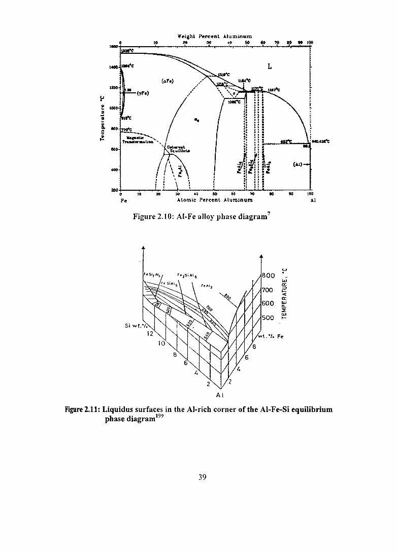
t<COO
~ 11 "--:! g,
.~ e ~
too.
40IJ
:&OD
W~i,hL Pen:~nt Aluminum
• 10 M ~ ~.o 60 et
IWt'
~"l: L
(ate)
" " := .. ;= " " " " t'
--~ :: ..... - " ~""'U"-" ... .: " . J~ !.r :!i j ••
5~ " . · 't , • " . · · :1 : • · · :1 .. = t
0 10 20 JI> 00 50 ~~ lO eo Fe A tomic Percent Aluminum
Figure 2.10: AI-Fe alloy phase diagram7
Al
')0
u . w a: ::J t« a: w Q.. ~ W t-
Fe
. t
III !!lD
A.I
Figure 2.11: Liquidus surfaces in the AI-rich corner of the AI-Fe-Si equilibrium phase diagram199
39

AlsFeSi forming early during solidification tend to prevent the flow of liquid metal
through the feeding channels causing unsoundness. Although other Fe-rich phases are
also as hard and brittle as the p-phase, they have less detrimental shapes.
The conditions favouring the formation of a. or p intermetallic phase depend
not only on the alloy composition but also on the solidification conditions. The
interesting aspect of p-phase reaction is that unlike the silicon eutectic temperature,
which is only slightly affected by variations in cooling rate, the p-phase start
temperature decreases with decreasing iron content, increasing cooling rate and
increasing melt superheat temperature until it eventually starts with the silicon
eutectic temperature. 143, 200, 201 The formation and presence of Fe containing
intermetallic phases (in particular p-phase) are also believed to produce significant
reductions in the castability of aluminium alloys. When Fe is added to aluminium to
produce a binary alloy, increased Fe levels result in increases in both the shrinkage
porosity and the melt viscosity without any change to surface tension.4
On the other hand, the presence of Fe (in excess of 1%) is also necessary
particularly in the case of die casting to prevent the molten alloy from sticking to the
casting die, often referred to in the trade as "soldering to the die". However, such high
amount of Fe poses problems due to p-phase formation.3o In order to obtain very good
mechanical properties, either the Fe content in the alloy has to be maintained as low
as possible or the morphology of the p plates has to be altered to harmless shapes. 110
Since Fe cannot be economically removed from the melt, it is technically importarlt to
understand the effects of iron and the means to reduce its ill effects.
2.4.3 Effect of Fe on the Properties of AI-Si Alloys
Three reviews on the effect of Fe in Al casting alloys published in 1981, 1997
and 2003 by Couture202, CrepeaullO and Mbuya et al203 respectively are available for
ready reference. However, because of the topic's continued significant importarlce in
AI industry, further contributions have been confirmed to be made by researchers.
40

1.4.3.1 Physical properties
The electrical resistivity of aluminium increases from about 2.6548 x 10⁻⁸ n m
at 20°C to about 2.75 x 10⁻⁸ n m and 2.9 x 10⁻⁸ n m with the addition of 0.05% Fe
and 1 % Fe respectively. The lattice parameter of aluminium is practically unchanged
up to the equilibrium solid solubility limit (0.05% Fe), but shrinks from 4.049596 x
10.10 m at 25°C to 4.012 xlO-10 m when 8.4% Fe is retained in solid solution by
quenching from the liquid. The density varies linearly from 2690 kgm-3 at O%Fe to
3770 kgm-3 at 36%Fe. Iron decreases the thermal expansion coefficient of aluminium
linearly. The solidification shrinkage of aluminium also decreases linearly from 6.5%
to 3% for a 5% Fe alloy. The viscosity of molten alloy increases with addition of Fe,
but there is no appreciable change in surface tension. When Fe is deposited on
aluminium, a layer of AhFe forms and this slows down diffusion. Solution of Fe in
molten aluminium is diffusion dependent and its activation energy is 1.04eV. Iron
does not appreciably affect other metals in solid aluminium, but the activation energy
for diffusion of Fe dissolved in aluminium is lowered by silicon from a value of
1.65eV for pure AI-Fe alloy to 1.35eV for the alloy containing 0.12%Si.8
2.4.3.2 Thermal conductivity
In the Al-Fe system, increasing the Fe content reduces the thermal
conductivity of aluminium. Makhlouf et al204 have studied the effect of Fe on the
thennal conductivity of AI-Si die casting alloys (based on 7 and 13% Si) and found
that Fe decreases the thermal conductivity. In the alloys studied by Makhlouf et al,204
the Fe-rich phases containing mainly Fe, Al, Mn, Cr and Ni have existed in the form
of needles, Chinese script and/or polyhedral (star-like) crystals. The needle phase has
the largest surface/volume ratio and hence has the largest interfacial area with the
alloy matrix. Consequently, this phase affects the thermal conductivity more than the
other phase morphologies. Manganese additions can transform the needle Fe-bearing
phases to Chinese script or polyhedral crystals, thus reducing the negative influence
of Fe on thermal conductivity. Other elements that change the needle morphology of
the Fe-bearing phases to morphologies with less surface/volume ratios are also
expected to reduce the negative effect of Fe on thermal conductivity.
41
2.4.3.3 Corrosion resistance
Although the difference in the electrolytic potential between that of AbFe
particles (ranges between -D.39 and -D.S8 V) that are usually present in the AI-Fe
system and that of the aluminium matrix (--0.80 V) is small (-0.40 V), it leads to a
reduction in corrosion resistance of Fe added aluminium. The purer the aluminium,
the more pronounced the effect; the fIrst few hundredths per cent of Fe are in solid
solution, and are segregated at the sub-grain boundaries and grain boundaries of the
aluminium and therefore lead to intergranular corrosion. Successive additions of Fe
fonn AhFe particles dispersed throughout and shift the corrosion from intergranular
to the pitting type.8 Hatch205 reported that Fe forms constituents (AhFe) that are
cathodic to the aluminium matrix. When these are present on the surface, the oxide
film over them is thin or non existent. The local cells produced by these impurities
promote pitting attack of the surface in a conductive liquid. In AI-Si foundry alloys,
Fe reduces signifIcantly the corrosion resistance unless corrected with Mn or Cr.
However, Fe together with Ni in AI-Si alloys produces particularly good resistance to
the effects of high temperature water or steam.206
2.4.3.4 Mechanical properties
The mechanical properties of cast aluminium alloys are adversely affected by
Fe because it is generally present as large primary or pseudo-primary crystals or as
Fe-bearing intermetallic compounds increasing the hardness but decreasing most
other mechanical properties such as ductility. The morphology of Fe-bearing
intermetallic compounds plays a deciding role in determining the mechanical
properties of the alloy. Although many Fe-rich phases are likely to form, the most
detrimental phase to mechanical properties is the needle/platelet p-phase. Wang et
al207 have reported that this is mainly because of the more severe stress concentration
effect introduced by the sharp edges of the needles into the alloy. Despite the
availability of number of publications on the effect of Fe in aluminium alloys, there is
no unanimity on the degree of its influence on mechanical properties. This is
especially so when its effect on the tensile and yield strengths of AI-Si based foundry
alloys is considered. Some researchers4, 8, 88, 205 have reported that Fe slightly increases
the tensile and yield strengths of aluminium alloys although others208-213 have
observed a decrease in both tensile and yield strength with increasing levels of Fe in
42

these alloys. However, there seems to be consensus on the fact that Fe increases
hardness and it greatly reduces the fracture toughness,4, 8, 88, 20S, 210, 211, 213-217 ductility,
4,8,88, 20S, 208-210, 212-217 fatigue resistance42, 213, 218 and impact energy.88, 210, 216
According to Couture,202 although there is no unanimity amongst various
sources in the literature as to the level of enhancement in mechanical properties
obtained with the addition of iron, there is consensus, however, on its detrimental
influence in the fonn of the p-phase. It has been found that at higher Fe content (>0.6
wt.%) in AI-Si alloys, the Fe-rich intennetallic phases are potential fracture initiating
sites than the eutectic Si?19 Appearing as needles in the microstructure, the amount
and size of the p-phase platelets fonned are strongly dependent on the Fe content and
solidification rate. 199, 208 According to Mascre,220 the p-phase has a detrimental
influence on the properties only when it is in the primary state; when it is part of a
eutectic, its effect may be negligible or even beneficial. Grand22I has found that
increasing iron from 0.17 to 0.60% in Al-7Si-0.3Mg alloy cast in shell moulds has no
effect on the tensile strength but has markedly reduced elongation. Lemon and
Hunsicker222 have observed that Fe up to 0.5% decreases the elongation markedly but
has little eff~ct on the tensile and yield strengths of Al-5Si-l.3Cu-0.5Mg and AI-7Si
O.3Mg alloys cast in permanent moulds. Murali et al223 have found that an increase in
Fe from 0.2 to 0.8% in Al-7Si-0.3Mg alloy decreases the strength (15%) and ductility
(50%) but increases the hardness (12%). Further, it has been observed that p-phase
(AlsFeSi) fonnation in Al-7Si-0.3Mg alloy reduces the dynamic fracture toughness
sharply.224 With increase in volume percent of 1t phase, a portion of Mg available in
the alloy will be consumed whereby the amount of Mg available for MgzSi precipitate
fonnation is reduced. This will lead to decreased strength properties in the heat treated
Al-7Si-0.3Mg alloy containing large amount of Fe. Closset and Gruzleski22S have
studied the effects of Fe and Mg on the properties of Sr-modified alloys. It has been
observed that Fe decreases the quality index dramatically. This decrease is primarily
due to its effect on elongation, which decreases from 12.7% at 0.1 % Fe to about 3.8%
when Fe reaches 0.36% (Mg has also caused a slight decrease in elongation).
Variations in Fe and Mg have given rise to several changes in the intermetallic
compounds observed in the eutectic. Vorren et al88 have observed that a reduction in
the Fe content from 0.30 to 0.15% in Al-7Si-0.3Mg alloy has resulted in a 20-25%
43

increase in fracture toughness. They have also reported about 47% and 20-25%
reduction in tensile elongation and impact energy respectively with increasing iron
content from 0.15 to 0.30%. Murali et al26 have reported that the maximum allowable
amount of Fe in AI-7Si-0.3Mg alloy should be between 0.3 to 0.4% to obtain the
desired mechanical properties and fracture toughness. The upper pennissible limit of
Fe content in AI-7Si-0.3Mg cast components for general use is approximately 0.25%,
while it is 0.10% or lower for castings used in critical load-bearing applications.
2.4.4 Techniques to Neutralize the III Effects of Fe in AI-Si Alloys
The detrimental effect of iron can be minimized by one of the following
techniques and/or their combinations: (i) Rapid solidification (ii) Superheating of melt
(iii) Addition of trace elements and (iv) Low temperature working. All of these
methods convert the crystallization of the platelet/needle like B-AIsFeSi phase to
either the less hannful Chinese script fonn or reduce the platelet size to fmer sizes.
Each one of these methods has its own advantages and limitations.
2.4.4.1 Rapid solidification
Rapi~ solidification is one of the methods of improving the mechanical
properties of AI-Si-Fe alloys by controlling the size of intennetallic compounds.226,227
It involves solidifying the melt at a very high cooling rate and is applicable only at
low levels of iron and silicon?27 It has been found that higher cooling rate increases
the maximum solubility of Fe in the aluminium matrix and limits the time for growth,
resulting in fine B-phase in the case of metallic mould castings and the disappearance
of all intermetallics when the cooling rate is as high as - 1500 Kfs experienced in
water quenched samples.228 At low cooling rates -0.50 K/s, the B-AIsFeSi needles are
thick and precipitate mainly at grain boundaries leading to serious alloy
embrittlement. Increasing the cooling rate (;:::100 K/s) results in the precipitation of
fme ~-phase needles well distributed in the microstructure. It also increases the
maximum solubility of Fe in the AI matrix. Consequently, a higher iron concentration
could be tolerated in AI-Si foundry alloys, especially for die casting applications,
where the presence of iron is essential to prevent problems of welding or soldering of
the castings to the die.229 However, this method is not amenable for mass production
due to its high cost and low productivity. Further, it is impossible to produce the same
44
high solidification rates throughout the castings having varying section thicknesses
made by conventional casting processes.
2.4.4.2 Melt superheating
Mondolfo and Barlock23o have studied the effect of superheating of several
aluminium alloys cast at different cooling rates « 0.1 to < 200 Kls) and found that the
higher superheat has resulted in faster solidification rate and finer the microstructural
constituents. Awano and Shimizu231 have demonstrated a novel method of
neutralizing the effect of Fe (0.1, 0.5 and 0.9%) in Al-7Si-0.3Mg alloy by
superheating the melt to high temperatures (973-1223 K) before pouring. It has been
found that superheating of the melt transforms the AlsFeSi needle shaped compounds
to Chinese scripts and thus increases the toughness of T6-treated squeeze cast alloy
experiencing high solidification rate. Iglessis et al227 have explained the growth
process of a. and f3 phases in the ternary Al-Si-Fe system when the melt is superheated
to a high temperature. Anantha Narayanan et al143 studying the effect of superheating
(200 to 300 degrees above the liquidus temperature) on the crystallization behaviour
of iron containing intermetallic compounds in Al-6Si-3.5Cu-1.0Fe aluminium alloy
have observed the crystallization of Fe compounds in a. - phase (Figure 2.12). This is
due to the fact that when the melt is superheated to a high temperature, the y alumina
transforms to a. alumina, which is a poor nucleus for the f3 phase crystallization
leading to the formation of a. phase. Superheating of Al-7Si-0.55Mg melt has been
found to change the morphology of the Fe-rich phase from a needle like to a skeleton
like structuie.232 Ahmad and MarshaU I96 have found that superheating (983 to 1273
K) of AI-Si alloys (Al-7.85Si-0.42Mn-1.12Fe-3.5Cu-2.2Zn and AI-l1.86Si-0.44Mn-
1.94Fe) refmes the massive plates to compact globular forms and hence results in
improved strength values of the alloys.
Bian et al233 and Liu et al234 have investigated another aspect of the conversion
of the p-platelets through melt superheating. According to them, in any Al-Si alloy
where the iron content is between 0.8 and 1.8%, the morphology of the iron
compounds changes from a long needle-like form to rosettes and thereafter to a
spheroidal shape as the melt temperature changes from low to high (from < 1113 to
45

(b)
~ ~ 41' . f)
Figure 2.12: Micrographs of AI-6Si-3.SCu-1.0Fe alloy (a) superheated to 1023 K and (b) 1123 K prior to casting (cooling rate=283 Kls) (Courtesy: Anantha Narayanan et a1143 )
46

1253 K). This spheroidization treatment has increased the tensile strength and
ductility of the alloy considerably and the spheroidal fonn is retained even after
remelting. Samuel et al228 investigating the effect of melt superheat (923, 1023 and
1296 K) on p-AIsFeSi phase fonnation in A380.1 (AI-9.14Si-3.22Cu-l.01Fe), 319.2
(Al-6.23Si-3.77Cu-0.46Fe) and eutectic Al-13Si;.1.5Fe-(O-O.6)Mg alloys, have found
that higher superheat temperature leads to refinement of the eutectic Si and p-AlsFeSi
intermetallics. However, it should be borne in mind that superheating the molten
metal to high temperatures will lead to increased hydrogen and oxide inclusion
contents apart from spending more for energy.
2.4.4.3 Low temperature working
Kim et af35, 236 and Umezawa and Nagai237, 238 have applied a new low
temperature working process to AI-7Si-1Fe alloy to control the size and shape of
intermetallic compounds and eutectic Si particles. The process consists of repeated
cold working at 77 K and recovery treatment at 793 K. It has been founq that the
eutectic Si and acicular p-AlsFeSi phases are broken down to spherical shape of 2-3
IlIl1 size. The refmed particles are also unifonnly distributed increasing the strength
and the elongation of the alloy.
2.4.4.4 Chemical neutralizers
The most common method of mitigating the ill effects of Fe in AI-Si alloys is
by adding trace elements. Various elements like Mn, Cr, Be, Co, Mo, Cd, Ni, S, V,
ell, Ca, and RE (La, Ce, Y, Nd) have been found to neutralize the ill effects of Fe in
the cast alloys to different levels either individually or in combination with other
elements. Each element has its own advantages and limitations. In all the cases,
neutralization results in modifying the morphology of Fe - rich compound from a
brittle to a less brittle form - i.e. from platelets/needles to globules or even Chinese
script. Table 2.6 gives the atomic size, crystal structure and maximum solid solubility
of various elements in pure aluminium at eutectic temperature. There is a critical ratio
between the trace element and Fe content for effective neutralization. Higher ratios
can form other undesirable intennetallic compounds. Table 2.7 lists the optimum
amount, the resulting morphological change, the advantages and the limitations of
various Fe neutralizers investigated for Al-Si alloys.
47

Table 2.6: Atomic size, crystal structure and maximum solid solubility of various elements in pure aluminium at eutectic/peritectic temperature
Element Atomic Crystal Eutectic (Peritectic*) Maximum solid Size structure temperature solubility (Aj eK) (wt.%)
Be 1.133 Hexagonal 918 0.063 close packed
Mn 1.24 Cubic 931 1.82
Cr 1.249 Body-centred 933* 0.77 cubic
Co 1.243 Hexagonal 933 <0.02 close packed
Sr 2.151 Cubic close- - -packed
Ca 1.973 Cubic close- 893 <0.01 packed
48

~
\0
Tab
le 2
.7:
Op
tim
um
am
ou
nt,
mo
rph
olo
gic
al
ch
an
ge,
ad
van
tag
es
an
d l
imit
ati
on
s o
f v
ari
ou
s ir
on
neu
trali
zers
in
AI-
Si
all
oy
s
Ele
men
t O
pti
mu
m
Mo
rph
olo
gic
al
Ad
van
tag
es
Lim
itat
ion
s R
ef.
amo
un
t chan~e
Mn
M
n:F
e= 1
:2
plat
elet
/3-p
hase
to
(l
-i)
Im
prov
es s
tren
gth
and
i) "
slud
ge"
form
atio
n w
hen
26,8
8,
Chi
nese
scr
ipt
duct
ilit
y (M
n+F
e) >
0.8
ii) h
ot te
arin
g 19
5,20
2 A
hs(F
eMn)
3Sh
phas
e ii
) L
east
exp
ensi
ve
iii)
dam
agin
g o
f fur
nace
wal
ls
elem
ent.
iv)
Do
not
impr
ove
frac
ture
to
ughn
ess
Be
0.26
% p
er
plat
elet
/3-p
hase
to
(l
-i)
Impr
oves
str
engt
h T
oxic
26
,88,
I%
Fe
Chi
nese
scr
ipt
duct
ili t
y an
d fr
actu
re
195,
202,
B
eSiF
e2A
Is p
hase
to
ughn
ess
239
Cr
(Cr+
Fe )
/Si=
2.2
plat
elet
/3-p
hase
to
(l
-B
ette
r th
an M
n a
ddit
ion
as
i) S
ludg
e fo
rmat
ion
26,8
8,
Chi
nese
scr
ipt (
l-
evid
ence
d by
hig
her
ii)
Do
not
impr
ove
frac
ture
19
5, 1
99,
AI1
3(C
rFe)
4S4
phas
e du
ctil
ity
toug
hnes
s 20
2
Co
Fe/
Co=
1 to
2
plat
elet
/3-p
hase
to
(l
-i)
Impr
oves
tens
ile
i) p
oor
duct
ilit
y 2
6,2
02
C
hine
se s
crip
t pr
oper
ties
ii)J
ess
tend
ency
ii
) la
rge
amou
nt o
f Co
is r
equi
red
AI9
(CoF
e)2
phas
e to
seg
rega
te d
urin
g so
lidi
fica
tion
C
a 0.
0035
-0.0
2 %
R
educ
es th
e si
ze o
f i)
Impr
oves
Im
pact
fra
ctur
e i)
Hig
her
amou
nts
lead
to p
oros
ity
30
,27
,39
, in
hyp
oeut
ecti
c pl
atel
et /3
-pha
se t
o to
ughn
ess,
dyn
amic
ii)
Exc
essi
ve a
ddit
ion
lead
s to
the
42
fine
r si
ze
frac
ture
tou
ghne
ss, t
ensi
le
prec
ipit
atio
n o
f Ca-
cont
aini
ng
I I
prop
erti
es
inte
rmet
aIli
cs
I I
Sr
0.02
-0.0
4% i
n R
educ
es th
e si
ze o
f Im
prov
es te
nsil
e pr
oper
ties
i)
Hig
her
amou
nts
lead
to p
oros
ity
228,
195
, hy
po eu
tect
ic
plat
elet
/3-p
hase
to
i) E
xces
sive
add
itio
n le
ads
to t
he
240,
241
fine
r si
ze
prec
ipit
atio
n o
f Sr-
cont
aini
ng
> 0
.1 i
n in
term
etal
lics
eu
tect
ic
Rar
e 1%
pl
atel
et /3
-pha
se t
o Im
prov
es m
echa
nica
l H
igh
amou
nt (
> 1
%)
redu
ces
155
eart
hs
Sph
eroi
dal
prop
eI!i
~s _
du
ctil
ity
and
stre
ngth
-
---_
......t.
---

2.4. 4. 4.1 Manganese
Mn is the most commonly used and the least expensive element for Fe
neutralization in Al-Si alloys. Since Mn is an impurity in secondary metal, it is not
always necessary to add it deliberately. It encourages the formation of a-phase, which
fonus in the interdendritic regions as well in the a-AI matrix?6, 242 In this respect, Mn
is considered to be more effective compared to Cr, Ni, Co and MO.243 The addition of
Mn to AI-Si alloys leads to the formation of quaternary (Al-Fe-Mn-Si) intermetallics.
According to the solidification conditions, the Fe-phase can precipitate as
three distinct morphologies: (a) polyhedral of star-like particles of sludge, favoured by
a high MnlFe ratio (~0.5, 195 where this sequence of precipitation is based on the phase
formation temperature), b) a-Chinese script (AI15(FeMn)3Sh) form that is less
harmful to mechanical properties, and c) P-Al5FeSi phase needles/platelets. Figure
2.13 illustrates Fe segregation during solidification of AI-7Si-0.3Mg alloy containing
0.48% Fe forming AI15(FeMn)3Si2 and Al5FeSi phases. As solidification progresses,
the composition of the remaining liquid follows lines I, 2a and 2b. Al1s(FeMn)3Sh
phase precipitates along line 2a. Both the phases precipitate along 2b and at point 3,
where the AI-Si eutectic also solidifies?44 However, the addition of Mn results in
other problems such as hot tearing or damaging of crucibles due to the crystallization
of a coarse AlI5(FeMn)3Sh compound, usually termed "sludge" or "fallout". This
problem usually arises in the die casting industry, where the melt holding
temperatures are generally kept low.228 The formation of sludge depends on the
cooling rate and the concentrations of Fe, Mn, Cr. Several empirical formulae have
been introduced in order to correlate the ratio between these elements and
precipitation of sludge. From the following formula195 for the segregation or sludge
factor,
Sludge factor (S.F) = %Fe + 2(%Mn) + 3(%Cr) .................. (2)
a value of 1.8 has been established for the formation of sludge. Under die-casting
conditions, the sludge factor could be as low as 1.4. The ASTM specification
indicates that in order to suppress the harmful influence of Fe in sand castings, Mn
content should be greater than one half of Fe content. The work of Gustafasson et al l99
confirms that when the Fe content exceeds 0.45%, it is preferable to increase the Mn
concentration to almost half that of the iron.
50

2.0r----------------------------------. wt"l.Fe
1.0
7 B 9
A1sFeSi
10 11 12 wt·/·Si
Figure 2.13: Simplified illustration of Fe segregation during solidification of 356 (Al-7Si-O.3Mg) alloy containing O.48%Fe.244
2.4.4.4.2 Chromium
Cr addition also exhibits a similar behaviour like Mn. Gustafsson et al,l99
studying the influence of Fe and Cr on the microstructure of cast AI-7Si-0.3Mg alloy
have found that the coarse ~-phase (AIsFeSi) platelets, which form during
solidification of alloys containing Fe. are replaced by Chinese script a(bcc)
[Ah3S4(Cr,Fe)4] dendritic particles when Cr is added. Coarse ~-phase platelets are
found to be replaced by a-script when Cr is added to 356 alloy containing - 0.5% Fe.2
However, its tendency to contribute to sludge formation limits its usefulness. The
precipitation of the a-phase in the form of large dense particles (sludge) in 339 alloys
containing relatively high-Cr has been reported by Granger?4S Mn and Cr additions,
however, do not significantly reduce the deleterious effect of Fe on fracture
toughness.88
2.4.4.4.3 Beryllium
Among the various iron neutralizers available, Be has been found to be the
most effective in improving the mechanical properties (optimum level is 0.26% Be
51

per 1% Fe) by exhibiting a constant hardness, strength and ductility irrespective of the
Fe level.26, 246 Belov and Kurdyumova247 have studied the AI-Si-Fe-Be alloy system
and found that Be is the most effective ferrous phase neutralizer in silumins. Tan et
aI2l2,214 have found that the addition of Be to A357 alloys is effective in decreasing
the deterioration of mechanical properties due tO'the presence of Fe. Be-AI-Fe phases
(A4BesFe2 and AIFeBe4) have also been observed in spheroidal compact forms with
0.2-0.5% Be addition.24s Warng et al249 have investigated the effect of Be addition on
microstructures and mechanical properties of B319 alloy. It has been found that the
addition of Be (i) reduces the amount and modify the morphology of iron
intermetallics from platelet like p-AIsFeSi phases to comparatively harmless Chinese
script a-AlsFe2Si phases, (ii) enhances the precipitation kinetics and increases the
amount of strengthening precipitates, (iii) spheroidizes and decreases the size of
silicon particles, (iv) increases the melting point of AI-AI2CU eutectic by about 280oK,
and Cv) improves the tensile properties. Murali et atl 10 have studied the changes in
morphology of the p-phase in the presence of Be in AI-7Si-0.3Mg alloy containing
0.6% Fe. Further, Be-Fe phases are seen only inside the a-AI dendrites resulting in
cellular fracture whereby improving the fracture toughness unlike the mixed mode of
intergranular. and brittle cleavage fracture in high Fe containing alloys without Be
addition. It has been found that Be addition is the most effective means in improving
the ductility and the tensile strength of AI-Si-Mg alloys.26, 224 Moreover, Be addition
has few other benefits apart from altering the morphology of the p phase. It acts as a
grain refmer and preferentially oxidizes forming BeO on the surface of the melt,
reducing Mg loss and making Mg available for forming the required volume of M~Si
for strengthening. In addition, Be improves the alloy fluidity/castability, especially in
the case of automotive alloys.240,2so However, since Be is toxic, foundrymen are
reluctant to use even small quantities of Be. Hence, efforts have been made to
minimise its amount by combining with other elements. Murali et atl6 have found that
Be added together with Mn and/or Cr seems to be the most effective way in providing
better tensile properties than individual Be addition. Samuel et al19S have studied the
effect of Be, Sr, Mn and Cr individually and in combination on p-AIsFeSi
characteristics and found that the classic neutralization treatment of using a Mn
52
addition with or without Cr could be replaced by the combined Be (0.08%) + Sr
(0.02%) addition.
2.4.4.4.4 Strontium
There are considerable evidences251.254 that Ca and Sr refine the detrimental
intermetallic compounds in wrought AI alloys. Morris and Miners253 have found that
addition of Sr or Ca in the range of 0.02-0.05% changes the ~ phase to a phase
thereby improving the surface characteristics of the extrusions and Ca and/or Sr
content above 0.02-0.05% has decreased the strength of the alloy. Sigworth255 has
reported that the formation of large brittle iron intermetallic phases can be suppressed
in an exceedingly well modified alloy. Haque and Kondic256 have indicated that Sr
has some positive effect on the reduction of the amount of intermetallics during
solidification of an AI-12.2%Si alloy. The amount of iron-bearing phase as well as the
primary Si phase are reduced or become negligible and the tensile properties are
improved by Sr treatment. The effect of Sr on changing the needle (~-phase) to
Chinese script (a-phase) morphology and also on the fragmentation of needles may
be compared with the effect of Sr on the modification of Si in AI-Si alloys. It appears
that there ary many similarities in nucleation and growth between intermetallics and
silicon.
Samuel et al241 have studied the effect of strontium (Sr) on the size and
distribution of ~-phase needles formed in 319 type alloys. The addition of 300 ppm Sr
seems to accelerate the dissolution of the ~-phase through fragmentation of the long,
intercepting needles that occur in the as-cast condition into small pieces. At such Sr
concentrations, the average ~-needle length is found to decrease from 130 to 70 JlIIl.
These observations have been supported by the microstructural analysis carried out by
Pennors et al,257 where the authors have attributed the decomposition of the ~-AI5FeSi
intermetallic phase to the possibility of Si rejection.
The influence of the addition of Sr as well as (Sr and Mn) on the Fe
containing intermetallic compounds in AI-6.5Si-3.5Cu-1.0Fe and AI-6.5Si-3.5Cu-
1.0Fe-0.3Mn (in mass %) cast alloys has been investigated. It has been found that Sr
successfully modifies the large highly branched ~-needle like phase (~-Al5FeSi) into
53

the individual less branched and finer ones. The combined addition of (Mn and Sr)
results in modification of the needle like p-phase as well as promotion of Chinese
script and sludge morphology fonnation. The mechanism of the above morphological
changes has been discussed in accordance with the mechanism of nucleation and
growth of the p-needle phase during solidification.258
2.4.4.4.5 Calcium
It has been reported that a small amount of Ca (40 ppm) is effective in
improving the fracture toughness even in alloys having relatively high iron content.39
An AI alloy containing 0.45-0.9% Mg and 0.2-0.6% Si has been widely used for the
production of aluminum extrusions. However, a principal cause of defects in the
quality of the extrusions is the breaking away of solid components from the surface of
the metal as it is forced through the die orifice, which is due to the presence of the
iron intermetallic, p AI-Fe-Si phase in the ingot during the extrusion process. Morris
and Miners253 have found that addition of Sr or Ca in the range of 0.02-0.05% has
changed the p phase to a phase thereby improving the surface characteristics of the
extrusions and Ca and/or Sr content above 0.02-0.05% has decreased the strength of
the alloy. It has been reported251 that the addition of 0.001-0.008% Ca has avoided the
fonnation of fir tree surface structures on the unidirectionally solidified billets [177-
305 mm diameter] and the sheet ingots of AAl100 [AI-0.95(Si + Fe)-(0.05-0.20)Cu-
0.05Mn-O.l OZn ],AA 1 050[ AI-0.25Si-0.40Fe-0.05Cu-0.05Mn-0.05Mg-0.05Zn-0.03Ti-
0.05V] and AA5005 [AI-(O.5-l. 1)Mg-0.20Mn-0.30Si-0.70Fe-0.20Cu-0. IOCr] Al
alloys regardless of the size of the billet/ingot. Further, a combined addition of
calcium 0.0005-0.05% (5-500 ppm) , Ti 0.0005-0.1% (5-1000 ppm) and B 0.0001-
0.02% (1-200 ppm) to iron containing (more than 0.2%) direct chill cast (D.C) Al
alloy (AAlOOO to AA5000 series) for rolling operation has eliminated the occurrence
of unwanted fir-tree structure on the surface, thus improving productivity?52
Kobayashi et al27, 39-42 have detennined the effect of Fe and Ca on the
mechanical properties and microstructural changes of lIS AC4C-T6 (AI-7Si-0.3Mg),
ns AC2B-T6 (AI-6.5Si-4Cu), and lIS AC4D-T6 (AI-5Si-l.5Cu-0.5Mg) alloys. The
properties are in general reduced when Fe is increased from 0.2 to 0.6% in the
absence of Ca. But, a distinct improvement in properties is noticed when Ca is added.
54

The addition of Ca (- 40 ppm) has refined the harmful plate-like AI-Fe based
intermetallic compound especially in high Fe content specimens as well as eutectic
silicon to a certain degree leading to the improved mechanical properties in all the
above alloys. The decreasing impact fatigue fracture toughness Kfc with increasing
iron content is found to improve with Ca addition. Similar beneficial effect of Ca is
observed with both the dynamic fracture toughness, Jd and the tearing modulus, Trnat,
of AC2B -T6 aluminium casting alloy (Figure 2.14). Except the observation by
Kobayashi et al,27,39-42 there is no comprehensive investigation of the effect of Ca on
Fe-intermetallics and its interaction with other elements in AI-Si casting alloys.
2.5 INTERACTION OF TRACE ELEMENTS
The interaction between trace elements present in aluminium alloys can be
either beneficial or detrimental to the properties of the alloys.
Among the various trace elements reported to react with Sr to neutralize its
modifying effect, both Sb and P are quite effective. Suzuki and Oshir0259 have
invented an improved method of eliminating P and/or Sb from molten aluminium by
Ca addition at a temperature of 923 to 1123 K and blowing chlorine gas or a chloride
to remove calcium phosphide or Ca-Sb compound forming dross. Bonsignore and
Daniels43,44 have found that additions of either Sr or Ca could scavenge Sb from
secondary molten aluminium. Sb content could be reduced to 50 from 2800 ppm by
treating the melt with 1500 ppm Ca. Ca and Sb form an insoluble intermetallic
compound, which separates out and probably combines with the aluminium oxide
surface dross. It is also observed that a minimum ratio of - 4: 1, by weight of Ca to Sb
appears to be necessary in ensuring an effective scavenging of Sb in A356 AI alloy.
Abdollahi and Gruzleski l35 have investigated the interactions between Sr and
Ca in sand cast A357 alloy through microstructural and thermal analysis studies. It
has been observed that deleterious calcium-strontium interactions take place when
both the elements are present simultaneously in the melt. This can be overcome by the
addition of higher amounts of calcium. Figure 2.15 shows the thermal analysis curves
obtained when Sr is present alone and in combination with varying amounts of Ca.
55
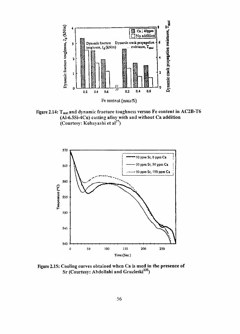
I 4 fo-I If
'a B ~ .S
H 3 Dynamic fcacture Dynamic cnck prDp.plion 6 U lou,hncss, Jd (kN/m) . ' resistance, T 11&1
... i A
0 ',:2
§ .. :.
I 1 B.
Go 1 i u
'B u .~
& 0 0 a >.
0.1 0." 0.6 Q
Fe content (mass%)
Figure 2.14: T mat and dynamic fracture toughness versus Fe content in AC2B-T6 (AI-6.5Si-4Cu) casting alloy with and without Ca addition (Courtesy: Kobayashi et a127)
~~~------------------------------------~
56S
$60
sso
S4S
o 50 100
'I - 50 ppmSr; 0 ppm Ca
-- SO ppm.Sr, SO ppm Ca ·1 I ,·-S.OppmSr,lSQ"pmCa
1'50
Tim~·(S'cc.)
2S0
Figure 2.15: Cooling curves obtained when Ca is used in the presence of Sr (Courtesy: Abdollahi and Gruzleski13)
56
It is seen that the eutectic plateau is depressed to a greater extent when Ca is
not added and is raised when both Sr and Ca are present together. The greater
depression of eutectic plateau observed without Ca indicates a high degree
of modification and the raising of plateau with both Ca and Sr indicates a reduction in
modification. In addition, it has been reported that 0.005% (50 ppm) Ca addition in
AC4CH alloy (Al-7Si-0.3Mg) influences the modification effect of Sr and shows a
coarse eutectic Si structure, indicating a reduced modification effect?60
Nakae et al261 probing the influence of impurity elements like Ca on
modification of eutectic Si in AI-Si alloys treated with Sr have observed (i) reduced
modification in commercial grade AI-Si alloy solidified with a cooling rate < 1 Klmin
due to the reaction between Sr and Ca released either from AI-Si-Sr master alloy or
furnace refractory (ii) perfect modification in high purity AI-Si alloy melted in a high
purity alumina tube and treated with Sr and cast even at slow cooling rate of 0.025
Klmin. (iii) significant obstruction to or total stoppage of modifying action of Sr with
the presence of 0.02 and 0.06 mass % Ca respectively and (iv) 0.01 to 0.02 mass %
Ca as the allowable limit in AI-Si alloy for modification by Sr. The mechanism
proposed is ~at Ca in the AI-Si-Sr alloy forms CaSh, which reacts with Sr forming
strontium - calcium - silicide.
EI-Hadad et al262 have investigated the effect of Ca addition on the
characteristics of eutectic Si particles in Sr modified 319 (AI-6.5Si-4Cu) alloys. It has
been found that Ca additions of 50 ppm and higher coarsened the Si particles due to
the formation of Al-Si-Ca-Sr compounds. Further, the form (rod or plate) and
chemical composition [Al7(Ca,Sr)Sh or Al2(Ca,Sr)Sh] of these intermetallic
compounds have been found to be strongly dependent on the Mg concentration in the
alloy.
Kurdyumov et all32 studying the effect of Li and Ca on the structure,
shrinkage, crack resistance and tlowability of AL2 [Al-12Si-0.6Cu] and AMg6 [Al
(5.8-6.8)Mg-(0.5-0.8)Mn-0.4Si-0.4Fe-0.2Zn-0.l Cu-(0.02-0.1 0)Ti-(0.0002-0.005)Be-
0.1 other impurities] Al alloys have established that Li and Ca affect the alloy
characteristics degrading their properties.
57

Vakhovbov et al263 have studied the combined solubility of Ca, Sr, Ba and Ti
in aluminium and detected the phase - equilibrium boundaries in the Al corner for Ca
Ti-AI and Ba-Ti-AI systems at 773 K. The positive role of Ti, Ca, Sr and Ba in
strengthening AI alloys has been reported. This has been attributed to the formation
and dispersion of TiAiJ, CaAl4, BaAl4 and SrA4"intermetallic phases, whose amounts
have increased with increasing content ofTi, Ca, Ba and Sr.
Kobayashi et al264 investigating the influence of impurity elements on the
morphology of primary silicon precipitates in hyper eutectic JIS AC3A AI-Si alloy
(Al-12.9Si) have observed the morphology of primary silicon as long and thin as well
as blocky shapes in super high (99.99%) and commercial purity (95%) hypereutectic
AI-Si alloys respectively. Further, the primary Si grows longer with lower
solidification rate in the former alloy, which could be suppressed by the addition of
small amount of Ca (150 ppm) and Fe (400 ppm). However, the growth rate of
primary Si morphology has not been affected by solidification rate in Ca and Fe
containing AI-Si alloy.
Afan~'ev and prudniko~65 have investigated the method of improving the
mechanical properties and formability of AI-Si piston alloys by optimising their
chemical composition. Such an AI alloy containing 18-20Si, 0.9-1.1 Cu, 0.5-0.6Mg;
O.8-0.9Mn, 0.07-0.09Ca, 0.2-0.4N, 0.1-0.2Ti, 0.01-0.03P and 0.00008-0.00025% H
has shown better mechanical properties than the known piston alloys of the AI-Si
system, as well as lower linear thermal expansion coefficient compared to the AI-Cu
alloys.
Studying the effects of increasing Ca content on the modification of AI-7Si
O.3Mg alloy with Sr, Kwon et at266 have observed (i) deterioration of eutectic
modification rate and increase in both primary a. and eutectic temperatures in 50 ppm
Sr treated alloy and (ii) decreased UTS and elongation as well as increased
intergranuIar fracture. Meanwhile, coexistence of Ca and P has been found to increase
eutectic modification rate and depress the eutectic temperature.
58

2.6 APPLICATIONS OF AI-7Si-O.3Mg alloy
AI-7Si-0.3Mg alloy finds widespread applications in automotive, aerospace
and general engineering industries. Sand cast AI-7Si-0.3Mg alloy fmds applications in
flywheel castings, automotive transmission cases, oil pans and pump bodies.
Permanent mould cast alloy is used in machine tool parts, aircraft wheels, airframe
casings and bridge railings. It is a general purpose high strength casting alloy, whose
range of applications is increased by its availability in the as-cast and heat-treated
condition as well. Figure 2.16 shows an AI-7Si-0.3Mg alloy wheel used in TATA
Indica and Ford Ikon cars. A typical strategic application of this alloy in Polar
Satellite Launch Vehicle (pSL V) and Geosynchronous Satellite Launch Vehicle
(GSLV) programmes ofIndian Space Research Organization (ISRO) is for making U
bracket, Interface and Engine mounting frame castings (Figure 2.17), which have
been developed at the Regional Research Laboratory.
2.7 GENERAL DISCUSSION
Various alloying elements have been found to have tremendous effect on cast
AI-Si alloys. However, each element has its own advantages and limitations. A
detailed literature survey carried out on the role of Ca in Al alloys87 reveals its
potential in enhancing certain important properties. However, a number of aspects
remain unclear and unanswered requiring detailed investigation for thorough
understanding. Na and Sr are the commonly used modifiers in AI-Si alloys changing
the eutectic silicon structure from acicular or plate-like to fine fibrous shape.
Variation in the efficiency of individual elements to promote modification is
discussed in terms of factors such as melting point, vapour pressure, free energy of
oxide formation, etc (Table 2.4). Na rapidly dissolves but does not oxidize; it has a
high vapour pressure and therefore evaporates easily. Hence, rapid fading and the
difficulties in storing and handling are the major drawbacks ofNa. Sr tends to oxidize
fairly readily but much less than Ca. Unlike elemental Ca, AI-Ca master alloys are
easy to handle and store like AI-Sr master alloys. However, Ca readily gets oxidized
to CaO affecting the castability especially fluidity. This can be overcome by adding
trace amount of Be. The melting points of both Ca and Sr are comparable with the
melt temperature. On the other hand, the vapour pressure of Sr is nearly four times
that of Ca, although, both are relatively low compared to Na. However, contradicting
59

Figure 2.16: Aura alloy wheel - peDt 08 (Hindalco) used in TAT A Indica and Ford Ikon cars
60

U-bracket
Interface frame
Engine mounting frame
figure 2.17: Premium quality AI-7Si-O.3Mg (A356) alloy castings for Space application (PSL V & GSL V Programmes of ISRO)
61

results are reported regarding modification effect, the fading behaviour and the
optimum amount of calcium for modification. The formation of Ca compound, CaSh
in AI-Si alloys with a Ca concentration greater than 500 ppm, detrimentally influences
the mechanical properties of these alloys. Hence, there is a critical concentration of
calcium up to which it is beneficial as a modifier in AI-Si alloys and beyond that it is
harmful. In addition, modification of eutectic silicon by Ca does not occur below a
critical cooling rate, regardless of the Ca concentration. Further, the mechanism of
modification by Ca is considered to be similar to that of Na165. 267 and needs further
investigation.
Similarly, contradictory results have been observed in the case of hydrogen
pick-up in Ca modified AI-Si melt. Some authors have found that Ca does not add
hydrogen to the melt but increases the amount of microporosity and reduces the
quantity and size of the macroporosity whereas others have observed hydrogen pick
up. In the case of Sr modified AI-Si melts, it has been reported that Sr does not alter
the regassing rate of melts and it ties up with the additional hydrogen in the melt as
hydrides.268 Since the values of free energy of formation of SrH2 and CaH2 are of the
same order viz., -14.63 and -14.76 kcallmole respectively, like Sr, Ca at very low
levels may tie up with the hydrogen present in the melt as hydrides leading to low
porosity. Beyond this critical level of Ca, Ca containing oxide film formed ruptures the
protective AhO) film leading to faster pickup of hydrogen. It may also be noticed that
the technique used by individual researcher, namely inert gas-melting (sintering)128 and
Alscan135 methods for hydrogen measurement is different. Hence, the effect of Ca on
the hydrogen pickup by aluminium melts is still in dispute and needs further
investigation.
Calcium interacts with other elements present in aluminium alloys. It
scavenges Sb from secondary AI alloys. However, admixtures of Li and Ca in AI
alloys affect the alloy characteristics degrading their properties. The simultaneous
presence of both Sr and Ca in the melt results in deleterious calcium-strontium
interactions. On the other hand, calcium addition results in an additive effect on Sr
modification and reduction in quantity and size of pores. 135 These observations are to
62

be taken into account for better understanding of the roles of Ca in AI-Si-Mg alloys.
It is evident39 that only a very small amount of Ca (0.004% = 40 ppm) is
sufficient to improve the tensile properties, fracture toughness, fatigue strength and
impact properties of even high iron containing Al alloys. Apart from changing the
morphology of the platelet Fe phase, since Ca also modifies the eutectic silicon, a
combined effect of iron neutralization and eutectic modification can be achieved by
Ca addition (40 ppm) to AI alloys having high Fe content. Except for the observation
by Kobayashi et al,39-42 there appears to be no comprehensive investigation on the
effect of Ca on Fe-intermetallics in AI-Si casting alloys. Be and Mn are the most
effective iron neutralizers in AI-Si cast alloys. Since Be is toxic, foundrymen are
reluctant to use even small quantities of Be. Hence, efforts have been made to
minimise its amount by combining with other elements. Higher amounts of Mn lead
to sludge formation which is deleterious to the properties of the alloys. Ca in
combination with Be and Mn can give better properties than both of these elements
added individually. Till date, no work has been done on the combined addition of
trace amount of Be, Mn and Ca. Further investigation needs to be carried out to study
the effect of Ca as an iron neutralizer and its combined effect with Be and other
alloying eleJ?ents in high Fe containing AI alloys. The mechanism of Fe
neutralization by Ca addition also needs to be understood.
2.8 SUMMARY
Properties of Al are usually enhanced by the addition of the major alloying
elements such as Cll, Si, Mg, Mn, Zn, Li, Ni, and then subjecting the alloys to various
thermal, mechanical and thermomechanical treatments. Some of the minor alloying
elements added to aluminium are Na, Sr, Sb, Ba, Ca, Be, Mn, Cr etc., to induce
specific changes in the microstructure. Iron is the most deleterious impurity element
found in cast aluminium alloys since it forms different intermetallic compounds with
AI, Si and other elements. Of these, p phase (AIsFeSi) is the most detrimental one in
degrading the mechanical properties especially ductility. The ill effects of iron can be
neutralized by either increasing the cooling rate or superheating the melt or adding
trace elements or low temperature working process. Among these, neutralization by
trace element addition is commonly practiced. Be, Cr, Mn, Co, and Rare Earths
changes the morphology of platelet iron intermetallic compound to harmless shapes
63

and improves the mechanical properties. Ca and Sr modify the eutectic Si and refine
the platelet iron intermetallic compounds thereby improving the mechanical
properties. A study on the role of Ca in AI alloys and their composites reveals its
potential in enhancing certain important properties. However, a number of aspects
remain unclear and unanswered requiring detailed investigation for understanding.
Some of them are: The fading characteristics of Ca in AI-Si melts and the exact
mechanism for modification of eutectic silicon by Ca and contradicting views on the
influence of Ca on hydrogen pickup by aluminum melts. Since Be is toxic, attempts
have been made to reduce the amount of Be by combining with other elements. Till
date, no work has been done on the combined addition of Be and Mn with Ca. Further
investigation needs to be carried out to study the effect of Ca as an iron neutralizer
and its combined effect with Be and other alloying elements in high Fe containing Al
alloys.
2.9 SCOPE OF THE PRESENT INVESTIGATION
Cast AI-Si alloys have widespread applications for structural components in
the automotive, aerospace, and general engineering industries because of their
excellent cas.tability, corrosion resistance and high strength-to-weight ratio in the heat
treated condition in particular. However, the use of these cast alloys is still limited in
comparison with wrought alloys, even though casting would be a more economical
production method. AIuminium alloys make up about 78% of the structural weight of
commercial aircraft, of which castings comprise only about 6%. Better quantitative
understanding of the microstructure-property relationships in cast Al alloys coupled
with improved foundry practice will allow wider application of reliable castings in
low mass structures. Further, in commercial purity aluminium there are many
naturally occurring impurities that can only be removed at great cost. Iron is probably
the most important one of these elements and detrimental impurity in cast aluminium
and its alloys and degrades the mechanical properties and fracture toughness. The cost
of aluminium alloys is inversely related to its Fe content. Indian commercial grade Al
is well known for its higher iron content and an understanding on the effects of Fe on
its alloys is a prerequisite for getting the best mechanical properties. Among the
various methods available to neutralize the ill- effects of iron, neutralization by
adding trace elements such as Mn, Cr and Be is commonly practiced. Mn is the most
64

commonly used and least expensive element. However, Be is carcinogenic and the
higher amounts of Mn and Cr required for neutralization lead to sludge formation
affecting machinability. Recent investigations 27,39-42,241,251-254,258 have revealed the
importance of eutectic Si modifiers for iron neutralization. However, very little work
has been carried out using modifiers viz., Ca and Sr in AI-7Si-0.3Mg alloy, a
commercially important alloy. In view of the fact that, modification is normally
carried out as a rule, and Fe content is unavoidable in AI-Si alloys, looking at Ca and
Sr and their combination with other elements used as Fe neutralizers would certainly
be worthwhile.
The objectives of the present investigation are:
(i) To study the dual roles (modification and Fe-neutralization) of Ca in
AI-7Si-O.3Mg alloy
(ii) Effect of Be, Mn and Sr as Fe neutralizers in Al-7Si-0.3Mg-xFe alloy
(iii) Comparison and interaction of the effect of Be, Mn, Ca and Sr added
Al-7Si-0.3Mg alloy at a constant Fe content on the morphological
change of p-phase and the tensile and impact properties.
65

CHAPTER 3
MATERIALS AND EXPERIMENTAL DETAILS
3.1 MATERIALS
Commercial grade AI-7Si-0.3Mg (LM25/356) alloy was used as the base
alloy. The chemical composition of the alloy is given in Table 3.1. Required amounts
of Ca, Be, Mn, Sr and Fe were added in the form of AI-lO% Ca, AI-5% Be, AI-10%
Mn and AI-10% Sr master alloys and AL TAB Fe compact (75% Fe and 25% AI)
respectively.
Table 3.1: Chemical composition (wt. %) of the AI-7Si-O.3Mg (LM25/356) alloy
Si Fe Cu Mn Mg Ni Zn Sn Pb Ti Balance
7.0 0.2 0.1 0.3 0.35 0.1 0.1 0.05 0.1 0.25 Al
3.2 MELTING AND CASTING
The alloy was melted in clay graphite crucibles of varying sizes in an electric
resistance furnace. Standard fluxing and degassing procedures using proprietary salt
fluxes and hexachloroethane tablets respectively were employed. For Fe
neutralization experiments, pre-alloyed ingots of AI-7Si-0.3Mg-xFe were prepared in
20 kg capacity crucible using ALTAB Fe compact (75% Fe and 25% AI). For all the
experiments, the processing temperature of the melt ranged between 993-1013 K.
Furtherdetails about processing are given in the individual chapters.
The alloying additions in the form of master alloys were immersed in the melt
at 1003 ± 5 K using coated and preheated mild steel plunger and stirred for 2-3
minutes to enable complete dissolution and homogenization and the melt was held at
this temperature for about 20 minutes (holding time). The melt was thoroughly

stirred, skimmed and poured (pouring temperature ranged between 993-1003 K) into
a preheated rectangular permanent mould (preheat temperature 573 K) and cylindrical
permanent and sand moulds (preheat temperatures 473 and 573 K respectively).
Figures 3.1 and 3.2 show the dimensions of the moulds used and castings made
respectively.
3.3 HEAT TREATMENT
AI-7Si-0.3Mg is a precipitation hardening alloy. The common heat treatment
procedure applied is solution treatment followed by quenching in warm water and
then precipitation or age hardening (T6 condition). The prescribed269 solution
treatment schedule is at 798-818 K for 12 hrs and age hardening at 428-448 K for 8-
12 hrs. In the present work all the tensile and impact specimens were solutionised at
808 K for 12 h, quenched in warm water (353 K) and aged at 438 ± 5 K for 8 h prior
to tensile and impact testing.
3.4 CHEMICAL ANALYSIS
The chemical analysis of the alloys studied (representative sample chips taken
by drilling) :were measured by ASTM E 34 and Instrumental- Inductive Coupled
Plasma (ICP) analyzer elsewhere. Recovery of about 90 and 75-80% was obtained
with Fe and Ca and Sr additions respectively.
3.5 THERMAL ANALYSIS
In thermal analysis, the cooling curve of a solidifying sample is recorded as it
cools from liquid state through the solidification range to solid. Thermal analysis was
carried out using MeltLab Aluminium Thermal Analyser (Figure 3.3). The molten
metal (about 100g) was poured into a preheated standard steel cup at 993 ± 5 K. The
solidification rate from the initial melt temperature was 1.50 K1rnin. Thermocouple
was placed at the centre of the cup and connected to a computer through an
analog/digital converter. The computer software program reads the temperature in
real time and plots a cooling curve on the monitor. For each melt, two cooling curves
were recorded to ensure the quality of the results. The liquidus temperatures, eutectic
temperature as well as the temperatures of formation of other precipitating phases
were determined from the cooling curves. Additionally, metallographic examinations
67

(a)
I I I I
I ---~~I , .---...... I ,,/.... , I
...L.-_+-_. --, ...... ~~ \,,", "-
/...... \. ,/1', / '~--...... \
I
(b)
027.5
Figure 3.1: Dimensions of (a) Rectangular slab mould and (b) Cylindrical mould used (All dimensions in mm)
68

1 o ....
Impact sample
_ \.------..v,------,
00,--1 __ >
(a)
OOL--I __ >
(b)
00,--1 _> Tensile sample
Microstructural sample
Figure 3.2: Dimensions of (a) Rectangular slab casting and (b) Cylindrical casting (All dimensions in mm)
69

Figure 3.3: MeItLab Aluminium Thermal Analyser
70

were carried out to correlate the results of thermal analysis with the corresponding
microstructures. The specimens were polished near the thermocouple region and
etched for microstructural observation.
3.6 DIFFERENTIAL THERMAL ANALYSIS (DTA)
The samples were subjected to differential thermal analysis using a SETSYS
apparatus from SETARAM (Figure 3.4). The DTA signal was recorded both on
heating and cooling at the scanning rate of 2° Kfmin over the temperature range from
313 to 1073 K. After a sample has been introduced in the sample crucible, this latter
was evacuated and filled with argon twice. A low argon flux was then fixed and
heating started. Each sample was analyzed twice to check the repeatability.
3.7 PHYSICAL CHARACTERISTICS
3.7.1 Density Measurement and Porosity Calculation
The density of the samples was measured using Archimedes' principle and
computed using the expression given below:
WaPl-~Pa P=------
Wa-~ ............................................. (3)
where 'W' is the weight and the subscripts 'a' and '1' refer to air and liquid (water in
the present work). From the density values, the % porosity can be calculated using the
following expression:
(Theoretical density - Measured density) %Porosity = x 100 (4)
Theoretical density ............ .
3.7.2 Electrical Conductivity
The electrical conductivity of the alloys was carried out usmg
'TECHNOFOUR' conductivity meter type 901 (Figure 3.5). The instrument works on
the principle of eddy currents. The probe induces eddy currents of a fixed frequency
71

in the test part. The magnitude of these eddy currents is directly proportional to the
electrical conductivity of the metal. These eddy currents generate their own electro
magnetic field which affects the electrical-impedance of the probe. Thus, conductivity
can be measured by measuring the corresponding changes in the probe impedance. It
reads the conductivity in percentage of International Annealed Copper Standards, in
the range of 10-110% IACS. The instrument was standardised often by setting the
instrument for the reference copper plates of 99% IACS and 17% IACS for accuracy.
3.8 MECHANICAL CHARACTERISTICS
The rectangular (210 x 60 x 38 mm) casting was used for making tensile and
V-notch impact specimens. Figure 3.1 shows the dimensions of tensile and impact
specimens. Tensile and impact testing were carried out in an Instron Universal
Testing Machine at a cross head speed of 2 mmlmin and Pendulum type Charpy
Impact Testing Machine (pSW-423) respectively. For each composition, four tensile
and impact specimens were tested and the average value was computed.
3.9 STRUCTURAL STUDIES
The structural features of the samples have been characterized using optical
microscopy, Image Analyzer, Scanning Electron Microscopy, Energy dispersive X
ray spectroscopy and Electron Back Scattered Diffraction analyzer.
3.9.1 Optical Microscopy
The specimens for microscopic examination were machined out from the
cylindrical castings [Figure 3.2(c)]. Additionally, metallographic examinations were
carried out in the thermal analysis samples (near the thermocouple region). The
samples were ground with emery papers of progressively fme grade 80, 220, 400 and
600 grits. The samples were turned through 90° between papers and washed
thoroughly with water before proceeding from one paper to the next. Final polishing
was performed in rotating discs of proprietary cloth (Selvyte cloth) charged with
diamond paste of 6, 3 and 0.25 J.llll particle size in sequence. Then the samples were
washed thoroughly with water and dried. The samples were etched in 0.5% HF
solution (0.5mlHF in 99.5ml water). Leitz metalloplan optical microscope was used
for metallographic analysis.
Figure 3.4: DT A equipment
Figure 3.5: TECHNOFOUR' conductivity meter
73

3.9.2 Image Analysis
Quantitative analysis of the microstructure was done usmg a Leica 2001
image analyzer in conjunction with the optical microscope. The silicon particle
characteristics (length, breadth, area, aspect ratio, equivalent diameter and density)
were measured. The fields of observations were selected randomly at different
locations of the sample. The size of j3-Fe intermetallic phase was measured manually.
In each case, at least ten fields were analyzed from a single specimen and the average
was computed.
3.9.3 Scanning Electron Microscopy (SEM)/ Energy Dispersive X-ray
Spectroscopy (EDS)lElectron Back Scattered Diffraction (EBSD)
The microstructures of the polished and fractured sample surfaces were
examined using' JEOL' Scanning Electron Microscope. The various phases observed
were identified using Energy Dispersive X-ray Spectroscope coupled with the SEM.
A JEOL-6460LA Scanning Electron Microscope equipped with an HKL EBSD
analyzer was used for studies by EBSD characterization. The system was operated at
20 keY with the sample tilted to 70°. The sample preparation includes mechanical
thinning of small specimens, polishing to a 1 ~m fmish and then ion beam milling.
Ion beam milling was conducted with 4kV Ar+, 10° beam tilt for 2 hours, and cooling
with liquid N2.
74

CHAPTER 4
EFFECT OF CALCIUM IN AI-7Si-O.3Mg ALLOY
Initially, Ca has been considered as one of the deleterious elements in
aluminum and its alloys and hence techniques have been developed for its re~oval. 32
Calcium, entering the aluminum casting alloys along with the addition of silicon and
appearing as calcium silicides, calcium phosphides and calcium nitrides, which are
considered to be hannful, requires removal to levels below 0.003% (30 ppm) and
preferably below 0.001 % (10 ppm).30 However, Ca introduced in the elemental form
modifies the eutectic silicon in AI-Si alloys/o-37 improves the fracture toughness and
impact properties of high iron containing recycled aluminum alloys,27,39-42 scavenges
the effect of Sb from secondary alloys,43, 44 imparts superplastic properties,45-49
and enables production of aluminum foams50-55 and alurninum metal matrix
composites. 56~ Aluminum alloys containing Ca as an intentional alloying element
are applied .industrially in the form of sacrificial anodes, bearings, electrolytic
capacitor cathode foils, packaging and others.65-86 The present study aims to
investigate the first two beneficial effects of calcium viz., modification and Fe
neutralization on the structure and properties of AI-7Si-0.3Mg and AI-7Si-0.3Mg-xFe
alloys respectively.
4.1 MODIFICATION
4.1.1 Methodology
AI-7Si-0.3Mg alloy was used as the base alloy. For each experiment, about 3-
4 kg of the alloy was melted in a clay-graphite crucible of 10 kg capacity using an
electric resistance furnace. The required amounts of calcium in the form of AI-I 0%
Ca master alloy to make calcium levels in the range 0-0.05% were immersed in the
melt at 1003 K using coated and preheated mild steel plunger and stirred for 2-3
minutes to enable complete dissolution and homogenization and the melt was held at
this temperature for about 20 minutes (holding time). The modification effect of Ca

has been compared with the well known modifier viz., Sr (0.02%), which was added
in the form of AI-lO% Sr master alloy. Figure 3.1 shows the dimensions (in mm) of
the moulds used and castings made. The casting and heat treatment procedures are
given in chapter 3.
4.1.2 Results and Discussion
4.1.2.1 Microstructure
Figure 4.1 shows the typical as cast microstructures of AI-7Si-0.3Mg alloy
without and with 0.01 % Ca, while Figure 4.2 shows those of the alloy treated with
0.02% Ca, 0.05% Ca and 0.02% Sr. It is seen that in Figure 4.1(a), eutectic Si
particles are in coarse acicular and platelet form. Only partial modification has been
observed in the alloy treated with 0.01% Ca [Figure 4.1(b)]. However, 0.02% Ca
shows a modified eutectic Si structure [Figure 4.2(a)]. On the other hand, 0.05% of
Ca addition has yielded a very fine fibrous eutectic Si [Figure 4.2 (b)] as well as leads
to the formation of an AI-Ca-Si compound which is identified as AbCaSh by
SEMlEDX analysis (Figure 4.3). When comparing the effects of Ca and Sr additions,
it has been observed that Sr addition leads to very fine globular eutectic Si. On the
other hand, Ca addition leads to the formation of both network and individual
globular eutectic Si. Quantification of the silicon particle characteristics using image
analysis in the as cast Ca added Al-7Si-0.3Mg alloys could not be done because of the
formation of eutectic Si in networks of fibrous form, wherein the identification of
individual Si is difficult.
4.1.2.2 Physical Characteristics
Porosity and electrical conductivity
Table 4.1 shows the effects of various amounts of calcium on the porosity and
electrical conductivity of Al-7Si-0.3Mg alloy. It is se~n that the % porosity increases
as the calcium content increases. The increased porosity at higher Ca levels may be
due to the increased melt affinity for gas absorption. When comparing the porosities
of 0.02% Ca and Sr added Al-7Si-0.3Mg alloys, it is seen that the porosity with Sr
addition is higher than that with Ca addition.
76

(a)
(b)
Figure 4.1: Typical as cast microstructures of AI-7Si-0.3Mg alloy treated (a) without and (b) with 0.01 % Ca
77

(b)
(c)
Figure 4.2: Typical as cast microstructures of AI-7Si-0.3Mg alloy treated (a) 0.02% Ca (b) 0.05% Ca and (c) 0.02% Sr
78
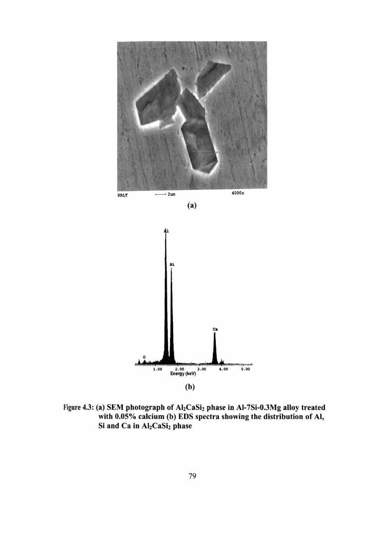
(a)
Si
Ca
1.00 2.00 3.00 4.00 5.00 Energy (keV)
(b)
Figure 4.3: (a) SEM photograph of AhCaSh phase in AI-7Si-0.3Mg alloy treated with 0.05% calcium (b) EDS spectra showing the distribution of AI, Si and Ca in AhCaSh phase
79

Table 4.1: % Porosity and Electrical Conductivity of AI-7Si-O.3Mg alloy treated without and with Ca
Alloy % Porosity Electrical Conductivity
AI-7Si-0.3Mg 1.47 31.2
AI-7Si-0.3Mg + 0.01 % Ca 1.40 34.8
AI-7Si-0.3Mg + 0.02% Ca 1.68 35.5
AI-7Si-0.3Mg + 0.05% Ca 2.84 33.9
AI-7Si-0.3Mg + 0.02% Sr 2.08 35.0
It is seen that Ca and Sr additions have increased the electrical conductivity
(in %IACS) compared to the untreated alloy. This is due to the modification of
eutectic Si by Ca addition, which allows easier flow of electrons compared to the
untreated alloy, where the platelet morphology of eutectic Si poses serious
impediment to the flow of electrons. On the other hand, the decrease in conductivity
with increasing calcium contents may be due to the higher amount of porosity present
in the samples. Nevertheless, the conductivity values of Ca treated alloys are still
higher than that of an untreated or unmodified alloy. When considering the effect of
porosity on %IACS, it is evident from the Table 4.1 that porosity has a significant
effect on %IACS. Though a very fine fibrous eutectic Si structure is obtained with
0.05% Ca addition, the presence of higher porosity has reduced the %IACS.
4.1.2.3 Mechanical Properties
Tensile properties
The effect of calcium on the tensile properties of T6-heat treated Al-7Si
O.3Mg alloy is shown in Figures 4.4 (a) and (b). Comparing the tensile strengths of
Al-7Si-0.3Mg alloy treated with and without Ca and Sr, it has been observed that the
tensile strength is decreased marginally with both Ca and Sr. This is due to the higher
porosity formation with the above additions. Similarly, comparing Ca and Sr
additions, UTS is lower in the case of Sr addition, which is due to the higher porosity
80
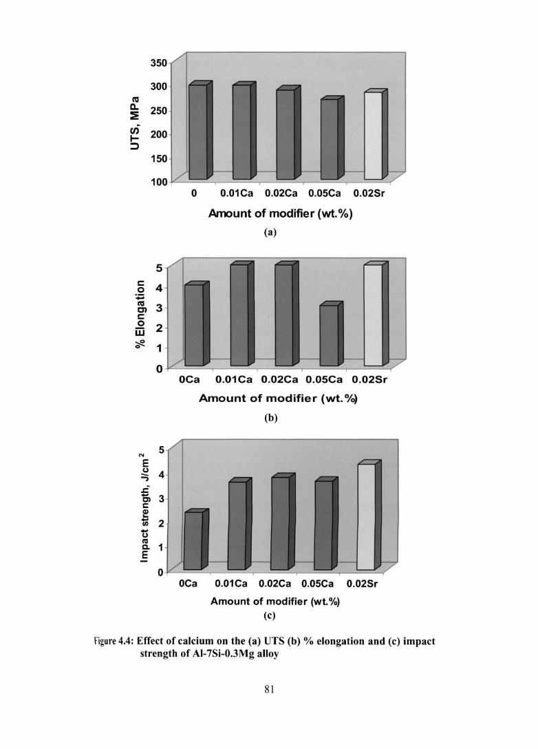
350
300 co c.. 250 :E
en 200 ~ ~
150
100~----~----~------~----~----~
5
g 4 :.;:;
~ 3 c: o iIi 2 ~ 1
o 0.01 Ca 0.02Ca 0.05Ca 0.02Sr
Amount of modifier (wt.%)
(a)
o ~----~------~----~----~------~
5
OCa 0.01 Ca 0.02Ca 0.05Ca 0.02Sr
Amount of modifier (wt. 0/0)
(b)
O~----~----~------~----~----~ OCa 0.01 Ca 0.02Ca 0.05Ca 0.02Sr
Amount of modifier (wt. %) (c)
figure 4.4: Effect of calcium on the (a) UTS (b) % elongation and (c) impact strength of AI-7Si-O.3Mg alloy
81

associated with Sr added sample. Both Ca and Sr additions lead to a significant
improvement (25% improvement) in elongation of AI-7Si-0.3Mg alloy. However,
when the Ca content is increased beyond 0.02%, the % elongation is decreased
dramatically. This is attributed to the over modification of eutectic Si, presence of AI
Ca-Si intermetallics and also higher porosity in the samples.
Impact strength
Figure 4.4 (c) shows the impact strength of Al-7Si-0.3Mg alloy with and
without Ca and Sr additions. It has been found that Ca and Sr additions improve the
impact strength significantly compared to the untreated alloy. Impact strength of AI-
7Si-0.3Mg alloy has been improved by 53, 62, 55 and 85% by treating the alloy with
0.01, 0.02, 0.05% Ca and 0.02% Sr respectively. This is due to the modification of
platelet eutectic Si to fibrous form. Figure 4.5 shows the SEM micrographs of the
fractured surface of impact tested Al-7Si-0.3Mg alloy without and with Ca and Sr.
Figure 4.5 (a) shows cleavage pattern typical of brittle fracture while Figure 4.5 (b)
shows few dimples along with the cleavage pattern. On the other hand, Figures 4.5
(c)-(e) show more dimples, a characteristic of ductile fracture. Though very fine
eutectic Si and more dimples are observed with 0.05% Ca, impact strength is almost
the same as that of 0.01 % Ca added sample. This is attributed to the detrimental effect
of AI-ea-Si intermetallics at higher calcium content.
4.1.3 Summary
1. The optimum level of Ca required for modification so as to get the best
mechanical properties lies in the range 0.01-0.02%.
2. Like Sr, higher amount of Ca also leads to the formation of higher porosity
and AI-Ca-Si intermetallics.
3. At 0.02% addition, Sr shows more porosity than Ca.
4. The properties obtained with Ca modification are at par with those obtained
with the well known modifier viz., Sr.
82

Figure 4.5: SEM micrographs showing the impact fracture surface of AI-7Si-0.3Mg alloy with and without Ca (a) 0% Ca (b) 0.01 % Ca (c) 0.02% Ca (d) 0.05% Ca and (e) 0.02% Sr
83

4.2 IRON NEUTRALIZATION
4.2.1 Methodology
Al-7Si-0.3Mg-xFe (x = 0.2 - 0.7%) alloys were prepared in a 20 kg capacity
crucible using AL T AB Fe compact (75% Fe and 25% AI). For each experiment,
about 3 kg of the alloy of known iron content was melted in a clay-graphite crucible
of 5 kg capacity using an electric resistance furnace. The melt was subjected to
fluxing and degassing using commercially available fluxes and degassing tablets
respectively. The required amount of calcium in the form of AI-l 0% Ca master alloy
was immersed in the melt at 1003 K using coated and preheated plunger and stirred
for 2-3 minutes to enable complete dissolution and homogenization and the melt was
held at this temperature for about 20 minutes (holding time). The casting, heat
treatment and testing procedures are given in chapter 3. The melt was cast into both
cylindrical and rectangular shapes, whose dimensions are given in Figure 3.2.
4.2.2 Results
4.2.2.1 Microstructure
Figures 4.6 (a) and (b) show the typical permanent mould as cast
microstructures of Al-7Si-0.3Mg alloy with 0.4 and 0.7wt.% Fe contents respectively.
It is seen that the microstructure consists of a large number of platelet Fe
intermetallics, platelet eutectic Si and primary aluminium. Further, it has been
observed that the size and volume fraction of the B phase increases with increasing
iron content. The platelet p-phase has been confirmed as AIsFeSi by SEMlEDX
analysis (Figure 4.7), which agrees well with the reported results.4, 8
Figures 4.8 (a-d) show the typical sand cast microstructures of AI-7Si-0.3Mg
xFe (x = 0.2 and 0.7%) alloys without and with calcium addition. As observed in the
permanent mould cast samples, the size and volume fraction of the p-phase increases
when the iron content is increased from 0.2 to 0.7wt.%. This observation has also
been confirmed by the significant increase in the average length of the p-needles
measured by image analysis with increasing iron content (Figure 4.9). It can also
be seen that Ca addition reduces the size of the platelets, which is again confirmed by
84

(a)
(b)
Figure 4.6: Typical permanent mould as cast microstructures of AI-7Si-0.3Mg alloy with (a) 0.4 and (b) 0.7% Fe
85

IUlLT
(a)
2.10 2.10 3,50 '.20 '.10 1.10 '.30 1.00 7.'
(b)
Figure 4.7: (a) SEM photograph of ~-phase in AI-7Si-O.3Mg-O.7Fe alloy and (b) EDS spectra showing the distribution of AI, Si and Fe
86

(b)
(c) (d)
Figure 4.8: Typical microstructures of sand cast AI-7Si-0.3Mg alloy with (a) 0.2% Fe, (b) 0.7% Fe, (c) 0.2% Fe + 0.01 % Ca and (d) 0.7% Fe + 0.01 % Ca in the as-cast condition
87

image analysis (Figure 4.9). Further, it has been observed that a higher amount of
Ca (0.05%) addition to AI-7Si-0.3Mg-0.6Fe alloy reduces the size of the platelet Fe
intennetallics to very fine form (Figure 4.10). It has also been seen that [me 13-platelets are precipitated along with the eutectic Si as clearly shown in the SEM
micrograph (Figure 4.11). Moreover, precipitation of AJ-Si-Ca intermetallic has also
been observed (Figure 4.10) which has been identified by SEMlEDX as AhCaSh
(Figure 4.12). This result is in agreement with the observations of Ware et al270 that
Ca-containing intermetallics form at high levels of Ca addition.
The eutectic Si in untreated alloys [Figures 4.6 and 4.8 (a) and (b)] is in coarse
acicular and platelet form, while it is in fine fibrous form in the alloys treated with
calcium [Figures 4.8 (c) and (d) and 4.10]. This shows the modification effect of
calcium. Quantification of the silicon particle characteristics in the as cast Ca added
alloys using image analysis could not be done because of the formation of eutectic Si
in networks of fibrous form, wherein the identification of individual Si is difficult.
The microstructures of AI-7Si-0.3Mg-xFe alloys with and without Ca in T6 condition
are shown in Figures 4.13 (a) and (b). The eutectic Si particles are more spheroidized
by Ca additi<?n [Figure 4.13 (b)], although they are spheroidized to some extent by T6
treatment. This observation has been confirmed by quantitative image analysis and
the various parameters measured are given in Table 4.2.
Table 4.2: Silicon particle characteristics of T6-heat treated samples
Silicon particle Al-7Si-0.3Mg-0.7Fe Al-7Si-0.3Mg-0.7Fe + characteristics Alloy 0.01 % Ca alloy
Length (J.Ull) 5.83 ± 3.41 5.42 ± 3.54
Breadth (Jlm) 3.56 ± 1.47 3.40 ± 1.67
Aspect Ratio 1.61 ± 0.44 1.55 ± 0.41
Equivalent diameter (Jlm) 4.12 ± 1.68 3.89± 1.89
The ± value in each case represents the standard deviation
88

Figure 4.14 shows the EBSD mapping result with back-scattered electron
image of AI-7Si-0.3Mg-0.2Fe+0.01 % Ca sample. If the crystallographic orientation
of neighbouring grains of aluminium in eutectic and primary dendrite is less than 5°,
the colour of mapping images is identical. The presence of many grains with different
orientations in eutectic area of Ca modified specimen (Figure 4.14) indicates the
existence of more than 5° orientation difference between neighbouring grains. It is
expected that neighbouring aluminium and silicon in the eutectic display the same
orientation. The EBSD patterns from aluminium and silicon are very similar since
aluminium has a fcc structure and silicon has a diamond structure. In the case of the
present measurement, the EBSD program was set for indexing of aluminium EBSD
patterns. This mapping result is in good agreement with the results of Nogita et al166
and Ware et af70. This shows the direct evidence of nucleation of the eutectic
heterogeneously in the interdendritic liquid and not from the primary dendrites.
Further, this suggests that the eutectic nucleated separately in the interdendritic melt,
but silicon and aluminium in the eutectic would still be expected to have a common
solidification interface.
4.2.2.2 Physical Characteristics
Porosity
The porosity of the sand cast cylindrical samples of AI-7Si-0.3Mg-xFe alloys
were calculated as per the details given in chapter 3. Figure 4.15 shows the effect of
various amounts of calcium on the porosity of Al-7Si-0.3Mg-xFe alloys and Table 4.3
gives the linear fit equations and the corresponding correlation coefficients. It can be
observed that the porosity level of the alloy increases as the iron content increases
from 0.2 to 0.7% for all calcium levels linearly with a correlation coefficient near to
1.0 for unmodified and 0.005% Ca added alloys. For the samples treated with 0.01 %
Ca, it appears that the porosity increases for 0.2-0.4% Fe and then remains constant
for 0.4-0.7% Fe. Hence, the fitted equation shows a lower coefficient of correlation of
0.8. Except for the 0.4% Fe + 0.01% Ca sample, the other calcium containing samples
showed lower porosity levels than the unmodified samples for each iron level. The
porosity for 0.2, 0.4 and 0.7% Fe containing alloys is consistently reduced by the
addition of 0.005% Ca, which may be attributed to the degassing effect produced
by low levels of calcium. Beyond this critical level of Ca, Ca containing oxide film
89
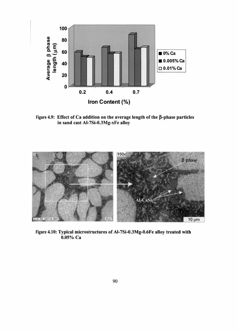
100
~ 80 co-.r. E Q. ::1. 60 co.. -
J:
& 0, 40 co s:::: ~ Q)
Q) - 20 ~
o 0.2 0.4
Iron Content (%)
0.7
.0%Ca
• 0.005% ca
o 0.01%ca
Figure 4.9: Effect of Ca addition on the average length of the ~-phase particles in sand cast AI-7Si-0.3Mg-xFe alloy
Figure 4.10: Typical microstructures of AI-7Si-0.3Mg-0.6Fe alloy treated with 0.05% Ca
90

Figure 4.11: SEM micrograph showing very fine Fe intermetallic phases in AI-7Si-0.3Mg-0.6Fe alloy with Ca (0.05%) addition
2.'0 ].10 ).10
Figure 4.12: (a) SEM micrograph showing the formation of AhCaSh phase in AI-7Si-0.3Mg-0.6Fe alloy with Ca (0.05%) addition (b) EDS spectrum showing AI, Si and Ca distributions.
91

(a) (b)
Figure 4.13: Typical microstructures of permanent mould cast AI-7Si-0.3MgO.7Fe alloy in T6 condition (a) without and (b) with 0.01 % Ca
Figure 4.14: EBSD mapping results of AI-7Si-0.3Mg-0.2Fe+0.Ol % Ca alloy
92

5.0,-------------------------------------~--_.
4.5
~ 4.0
'; ~ o a. 3.5 ?!-
3.0
• .0%Ca
I*------e 0.005% C ...
..... --...... 0.01% Ca
0.2 0.3 0.4 0.5 0.6 0.7 0.8
Iron content (wt.%)
Figure 4.15: Effect of Ca on the % porosity of AI-7Si-O.3Mg-xFe alloy
Table 4,3: Fitted equation and the correlation coefficient for the plot of % porosity versus % Fe content at various Ca levels
Amount of Fitted equation Correlation calcium (wt. %) coefficient, R2
0 % Porosity = 2.9998 + 2.5490 (% Fe) 0.9914
0.005 % Porosity = 2.1539 + 1.9571 (% Fe) 0.9609
0.01 % Porosity = 2.6698 + 3.1766 (% Fe) 0.7976
93

might have caused ruptures in the usually protective AhO) oxide film, leading to
I faster pickup of hydrogen. Figures 4.16 (a) and (b) are the optical and SEM
micrographs of platelet/needle like Fe intermetallic compound observed inside a
shrinkage pore in AI-7Si-0.3Mg-0.7Fe alloy.
Electrical conductivity
Figure 4.17 shows the effect of calcium on the electrical conductivity (in
%IACS) of AI-7Si-0.3Mg-xFe alloys. In the case of low Fe (0.2%) containing alloy,
conductivity increases with increasing calcium addition. This is due to the
modification of eutectic Si by Ca addition, which allows easier flow of electrons
compared to the untreated alloy, where the platelet morphology of eutectic Si poses
serious impediment to the flow of electrons. However, in the case of 0.4% iron
containing alloy, conductivity initially increases and then decreases with increased Ca
level. On the other hand, the conductivity of 0.7% iron containing alloy reduces with
increasing calcium content. The reasons for these observations are not fully
understood and may be attributed to the higher amount of porosity (Figure 4.16)
present in these samples.
4.2.2.3 Mechanical Properties
Tensile properties
Tensile testing was carried out on samples machined from the permanent
mould castings. Figure 4.18 shows the tensile properties of the alloys in the T6 heat
treated condition. It can be observed that the ultimate tensile strength CUTS) increases
marginally (2.2% improvement) as the Fe content increases from 0.2 to 0.4% for the
alloys without Ca addition. However, the UTS for the higher Fe content (0.7%)
sample remains the same as that of the 0.2% Fe alloy. Comparing the tensile strengths
0[0.2,0.4 and 0.7wt% Fe containing alloys treated with and without Ca addition, the
tensile strength is decreased slightly with Ca addition.
Figure 4.18 (b) shows a drastic decrease (74.3%) in % elongation of the alloys
without Ca addition as the Fe content is increased from 0.4 to 0.7%. This effect is due
to the increased amounts of (3-Fe intermetallic platelets dispersed throughout
the microstructure at higher Fe contents, leading to crack initiation and rapid crack
94

(a)
(b)
Figure 4.16: Micrographs of platelet/needle like Fe intermetallic compound observed within a shrinkage pore in AI-7Si-O.3Mg-O.7Fe alloy (a) Optical and (b) SEM
95

37
-rJ)
u ~ 36
eft. -~ :~ 35 .. (.) :::l "C c: o 34 (J
co (.) ·c t) 33 ~ W
0.0 0.1 0.2
•
.--~
0.3 0.4 0.5
Iron Content (wt.%)
• 0% Ca • 0.005% Ca ... 0.01% Ca
•
•
0.6 0.7
Figure 4.17: Effect of Ca on the %IACS of AI-7Si-O.3Mg-xFe alloy
96

350
300
~ 250 ~
uf 200 I-::J
150
100
8
c 0 :t:I
6 ca C)
4 c 0 W
~ 2
0
0
0.2 0.4 0.7
Iron conte nt, (wt. %)
(a)
0.2 0.4 0.7
I ron Content, (wt. 0/0)
(b)
.0%Ca
.0.005% Ca
00.01% Ca
.0%Ca
.0.005% Ca
00.01% Ca
Figure 4.18: Effect of Ca addition on the (a) UTS and (b) % elongation of AI-7SiO.3Mg-xFe alloy (T6 condition)
97

propagation in the alloy. The addition of Ca has improved the elongation of 0.2, 0.4
and 0.7% Fe containing alloys. The addition of 0.005% Ca to the 0.2,0.4 and 0.7% Fe
~loys leads to a 17, 12 and 22% improvement in % elongation respectively. Addition
of 0.01% Ca improved the % elongation by 18, 14 and 44% respectively compared to
the unmodified alloy. These observations are supported by the microstructural
observations on modification of eutectic Si and refinement of p-platelets with Ca
addition.
Figure 4.19 shows the SEM micrographs of the fractured surface of tensile
samples. At low Fe contents (0.2 and 0.4%) [Figures 4.19 (a)-(c)], there is no
significant difference in the fracto graphs of AI-7Si-0.3Mg-xFe alloys with and
without Ca. These fracto graphs exhibit dimpled structure typical of ductile fracture.
However, the embrittling nature of the p-platelets is evident in high Fe content (0.7%)
alloy [Figure 4.19 (d)].
The quality index (Qi71 values for the alloys have also been calculated using
the following equation and plotted in Figure 4.20.
Quatity index (Q) = UTS + 150 log (% elongation) ............... (5)
Higher the Q-value, the material will be both strong and ductile. It is seen from the
Figure that the quality index increases with increasing iron from 0.2 to 0.4% and then
decreases rapidly with further increase in iron to 0.7%. This is due to the rapid
decrease in the % elongation as the iron content increases from 0.4 to 0.7% [Figure
4.18 (b)] indicating that the quality index represents the relative ductility of the
material. Further, the higher Q-value with Ca addition compared to untreated alloys is
due to the improved % elongation with Ca addition.
Impact strength
Figure 4.21 shows the impact strength of Al-7Si-0.3Mg-xFe alloys with and
without Ca addition. It is seen that Ca addition significantly improves the impact
strength of the alloys compared to the untreated alloys. Improvement in impact
strength obtained in the 0.2, 0.4 and 0.7% Fe containing alloys with Ca addition are
44, 48 and 16% respectively.
98

Figure 4.19: SEM micrographs showing the tensile fractured surface of AI-7Si-0.3Mg alloy (T6 condition) containing (a) 0.2% Fe (b) 0.2%Fe + 0.005% Ca (c) 0.4% Fe + 0.01 % Ca and (d) 0.7% Fe + 0.005% Ca
99

460
440 lr;; •
>< 420 Q) 'C I:
~ 400
C'CI ::::J -----0% Ca a 380 ----..- 0.005% Ca
----A- 0.01 % Ca
360 •
340 0.2 0.3 0.4 0.5 0.6 0.7
Iron Content, (wt.%)
Figure 4.20: Effect of Ca on the quality index of AI-7Si-0.3Mg-xFe alloy in T6 condition
100

3.
N 3 E u ::; 2.5 ~
0, 2 c: ! u; 1.5 .. g 1 Q.
§ 0.5
o 0.2 0.4
Iron Content, (wt. %)
0.7
.0%Ca
• 0.005% Ca
00.01% Ca
Figure 4.21: Effect of Ca on the impact strength of AI-7Si-O.3Mg-xFe alloy
101
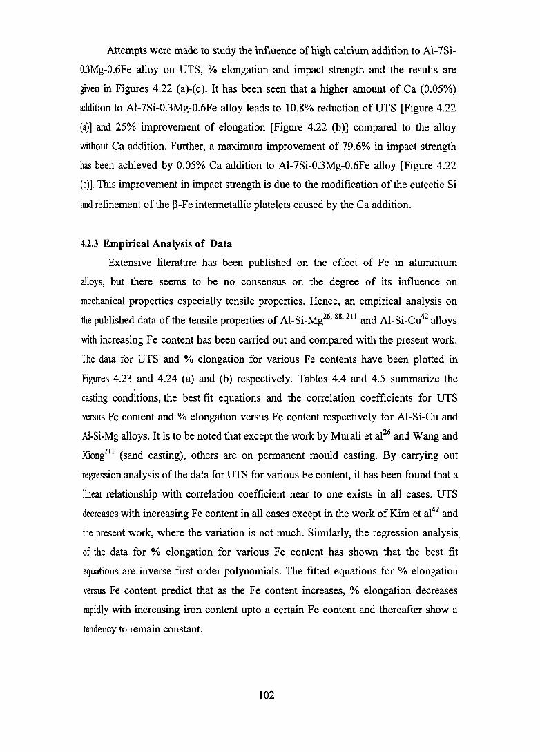
Attempts were made to study the influence of high calcium addition to Al-7Si-
0.3Mg-0.6Fe alloy on UTS, % elongation and impact strength and the results are
given in Figures 4.22 (a)-(c). It has been seen that a higher amount of Ca (0.05%)
addition to Al-7Si-0.3Mg-0.6Fe alloy leads to 10.8% reduction of UTS [Figure 4.22
(a)] and 25% improvement of elongation [Figure 4.22 (b)] compared to the alloy
without Ca addition. Further, a maximum improvement of 79.6% in impact strength
has been achieved by 0.05% Ca addition to Al-7Si-0.3Mg-0.6Fe alloy [Figure 4.22
(c)]. This improvement in impact strength is due to the modification of the eutectic Si
and refinement of the p-Fe intermetallic platelets caused by the Ca addition.
4.2.3 Empirical Analysis of Data
Extensive literature has been published on the effect of Fe in aluminium
alloys, but there seems to be no consensus on the degree of its influence on
mechanical properties especially tensile properties. Hence, an empirical analysis on
the published data of the tensile properties of AI-Si-Mg26, 88, 211 and Al-Si-Cu42 alloys
with increasing Fe content has been carried out and compared with the present work.
The data for UTS and % elongation for various Fe contents have been plotted in
Figures 4.23 and 4.24 (a) and (b) respectively. Tables 4.4 and 4.5 summarize the
casting conditions, the best fit equations and the correlation coefficients for UTS
versus Fe content and % elongation versus Fe content respectively for AI-Si-Cu and
Al-Si-Mg alloys. It is to be noted that except the work by Murali et al26 and Wang and
Xiong211 (sand casting), others are on permanent mould casting. By carrying out
regression analysis of the data for UTS for various Fe content, it has been found that a
linear relationship with correlation coefficient near to one exists in all cases. UTS
decreases with increasing Fe content in all cases except in the work of Kim et al42 and
the present work, where the variation is not much. Similarly, the regression analysis.
of the data for % elongation for various Fe content has shown that the best fit
equations are inverse first order polynomials. The fitted equations for % elongation
versus Fe content predict that as the Fe content increases, % elongation decreases
rapidly with increasing iron content upto a certain Fe content and thereafter show a
tendency to remain constant.
102

350
300 ca a. 250 ~
en 200 I-:::J
150
100
2
s::: 1.5 0 ~ ca en 1 s::: .2 w ~ Cl
0.5
0
Ne 3
C)
:::;
.£ 2 Cl c: I!! -rn ti 1 ('Cl
Co e
o
A B Alloy code
(a)
A B Alloy code
(b)
A B Alloy code
(c)
Figure 4.22: Effect of higher amount of Ca (0.05%) on the (a) UTS (b) % elongation and (c) impact strength of AI-7Si-0.3Mg-0.6Fe alloy (T6 condition) {A= AI-7Si-0.3Mg-0.6Fe and B= A + 0.05% Cal
103

Mcr~------------------------------------~I
360
340
320
(tt a. 300 6 (f) 280 ~
260
24Q
22Q
°0
o
• • .... _ .. _ .. _ .. _. _.'- '- '- -
• • • -• ---.eo-. --c.-_~ -o
"'0. .... -
. . 42 -•. --. Kim et al. 8B '0- - ..... 0 Vorten"efal. y - -_.y Ml!raJ!etal:26 211 A ,· .. · ..... A, Wang andXlCing •. _ .. -. Presentwork
-r.._ -J!!.
~0+---~.r---~-----r----~----~.--~r----4
0.0 0.2 0.4 0.6 O.S 1.0 1.2 1.4
Iron content (wt%)
Figure 4.23: Empirical analysis of the variation of UTS with iron content in AI-Si-Mg and AI-Si-Cu alloys
Table 4.4: Empirical analysis of data for UTS versus Fe content
Investigator Alloy Casting UTS Vs Fe (Linear fit)
Best fit equation Correlation coefficient, R2
Kim et al'!": Al-Si-Cu PM UTS= -15.8(%Fe)+324.2 0.9996
Vorren et al lSlS Al-Si-Mg PM UTS= -49.7(%Fe)+318.8 0.9990
Murali et al":!> Al-Si-Mg SM UTS= -39.9(%Fe)+25 1. 1 0.9996
Wangand Xiong211
AI-Si-Mg SM UTS= -65.2(%Fe)+286.8 0.9999
Present work Al-Si-Mg PM UTS= -15.l(%Fe)+360.7 0.9997
[PM = Permanent Mould; SM = Sand Mould]
104

12~--------------, 8~--------------------~
10
o
0.. \
• •
·_Pr __
a· - -0 Vorren et al~
2' 0' ..... 0()
0.0 0.2
~- . o ----0
0.4 0.6
Iron content (wt%)
(a)
• 0.8 1.0 1.2
7
6
c: o S
"" to
g 4 "i: .,. 3
2
0 0.0 0.2 0.4
.... ~ "" ..
0.8
_ lWnet,i2 O· - -0 M.iaI;.t Bi..2~ 'f'''''''f' Present~
...... . ,
Q.8 1.0
Iroll content ('M%}
(b)
Figure 4.24: Empirical analysis of the variation of % elongation with iron content in AI-Si-Mg and AI-Si-Cu alloys
Table 4.5: Empirical analysis of data for % elongation versus Fe content
Investigato,r Alloy Casting % Elongation Vs Fe (polynomial fit)
1.2
Best fit equation Correlation coefficient, R2
Kim et al42 AI-Si-Cu PM %Elongation = 1.5766+ 0.2295
(%Fe) 0,9995
Vorren et aI88 AI-Si-Mg PM %Elongation = -0.2781 + 0.4966
(%Fe) 0_9296
Murali et af6 AI-Si-Mg SM %Elongation = 2.4834+ 0.5931
(%Fe) 0.9991
Present work Al-Si-Mg PM %Elongation = 0.2663+ 1.3392
(%Fe) 0.8402
[PM = Pennanent Mould; SM = Sand Mould]
105

When comparing the present work with Vorren et al88 (both are AI-Si-Mg
system and permanent mould casting), the values of UTS and % elongation reported
in the latter are lower. This may be due to the varying mould wall thickness and
mould preheating temperatures used in the two cases (20 and 32mm mould wall
thickness and mould preheating temperatures· of 573 and 693 K respectively).
Similarly, the higher values of UTS achieved in the present work (permanent mould
casting) than those of Murali et af6 and Wang and Xiong211 (sand casting) is due to
the difference in the solidification rate. Higher solidification rate results in reduction
of the secondary dendrite arm spacing, less and better distributed porosity, reduction
in the size of Fe-intermetallic phases and a fmer eutectic Si structure. Further, it can
be seen from Figure 4.23 that the trend in the variation of UTS with increasing iron in
the present work is similar to the work ofKim et a1.42 on AI-Si-Cu alloy.
4.2.4 Discussion
Increasing Fe content from (0.2 to 0.7 wt.%) in AI-7Si-0.3Mg alloy results in
the precipitation of long needles/platelet B-phase, whose size and volume fraction
increase with increasing iron content.
Calcium addition has refmed the large platelet Fe intermetallics to very fine
fonn and modified the eutectic Si to fine fibrous form. However, higher amount of Ca
addition (0.05%) results in the precipitation of AhCaSh intermetallics. The
refinement of ~-platelets with Ca addition is due to the fragmentation of ~-platelets
by Ca. The reason for this fragmentation of the platelets could be attributed to the
rejection of Si at the ~-phase/ Al matrix interface. The higher diffusion coefficient2 of
Si in AI (10.11 to 10.8 cm2 S·I) compared to Fe (10.13 to 10.12 cm2 S·I) in the temperature
range 673 to 873 K would facilitate the destabilization of the ~-AI5FeSi phase
platelets in the presence of Ca. In the case of Sr, it has been reported273 that the
fonnation temperature of ~ phase is high enough to enhance the diffusion of Sr into
the ~-platelets (absorption), especially when the thickness of these platelets is of the
order I Ilm. Figure 4.25 schematic ally illustrates the decomposition of ~-Al5FeSi
platelets and the formation of Ca-containing intermetallics in Ca added alloys wherein
(a), (b) and (c) indicate low, sufficient and excessive Ca contents respectively. A low
106

·Si
OCa • Al-Si-Ca
Figure 4.25: Schematic illustration of decomposition of ~ platelets with Ca addition
107

level of calcium induces no changes in the I3-AIsFeSi platelets, whereas a sufficient
amount of Ca content leads to fragmentation of the I3-AlsFeSi platelets. On the other
hand, an excessive amount of Ca will lead to fragmentation of the I3-AIsFeSi platelets
and precipitation of Al-Ca-Si intennetallic phase respectively. As this intennetallic
phase is seen to be attached to the sides or the end of the l3-phase platelets, it could be
assumed that the Si rejected from the latter reacts with the Ca in the surrounding area,
leading to the fonnation of the AhCaSh particles. This has been further confinned by
the SEMlEDS analysis (Figure 4.12) of the AI-7Si-0.3Mg-0.6Fe alloy where the Al
Ca-Si compound is seen to be attached to the side of the l3-phase platelets. This is
further supported by the work of Samuel et a1 19s, 273 on Sr addition to 6111 (Al
O.65Si-0.32Fe-0.86Cu-0.21 Mn-0.89Mg-0.048Cr) and 319 (Al-6.2Si-3.7Cu) alloys.
It has been observed that the % porosity of the alloy increases as the iron
content increases from 0.2 to 0.7wt.%. This may be due to the difficulty in the
feeding of the liquid metal due to the presence of large intercepting l3-platelets. This
result is in accordance with the work of Samuel et al19s on the effect of trace elements
on ~-AlsFeSi characteristics, porosity and tensile properties of 319 (AI-6.2Si-3.7Cu)
alloy. I3-Fe platelets are often found to be associated with shrinkage pores,273, 274 and
this observation is understood to be the direct result of their effect in increasing
restrictions to feeding through the small interdendritic channels in the later stages
of feeding. It has been reported274 that the platelets are observed to fonn as an
interlocking network and grow around pre-existing features in the microstructure.
These relatively large and long l3-platelets intersect and reduce the size of the
interdendritic feeding paths, limiting feeding and thus increasing the driving force for
pores to fonn.
It is interesting to note that the % porosity of 0.2, 0.4 and 0.7% Fe containing
alloys is reduced with 0.005% Ca addition. This may be due to the degassing effect of
calcium at low levels. This is supported by the work of Velasco et al. 104 There are
several mechanisms that have been proposed to explain the changes in porosity that
occurs as a result of adding eutectic modifiers to AI-Si alloys. First, the porosity
fonnation at various Ca levels may be explained by the recent theory I 58 that porosity
108

fonnation in hypoeutectic AI-Si alloys is strongly dependent on the eutectic
solidification mode. EBSD analysis of the Ca-containing sample in the present work
indicates that the eutectic nucleates in the interdendritic liquid away from the primary
aluminiwn/liquid interface and the eutectic evolves with a front growing in a direction
opposite to the thermal gradient, while in unmodified alloys the eutectic nucleates
with a very high nucleation frequency adjacent to the dendrite tips throughout the
sample. This is further supported by the results of Knuutinen et al.130 showing a direct
relationship between porosity and eutectic solidification mode in A356 alloy treated
with different levels of Ba, Ca, Y and Yb. The principle implies the impact of the
different modes of eutectic solidification and thus spatial distribution of evolving
eutectic on the interdendritic permeability in the final stages of solidification. Such
considerations therefore account for the overall solidification and feeding occurring in
the sample, thus determining the overall feedability and feeding requirements of
different regions of the casting. Therefore, at the intermediate Ca level (0.005%), the
eutectic may display a mixed eutectic solidification mode, ie. between that of the
unmodified and Ca modified alloys, thus leading to a minimum of porosity for this
particular c~ting with its solidification and feeding pattern. The role of feeding
direction and influence of eutectic solidification mechanisms have been discussed in
detail by Dinnis et al?75 Secondly, In the case of Sr modified AI-Si melts, it has been
reported that Sr does not alter the regassing rate of melts and it can react with
hydrogen in the melt and precipitate as hydrides.268 Since the values for free energy of
formation of SrH2 and CaH2 are of the same order viz., -61.15 and -61.70 kJmor\
respectively,276 like Sr, Ca at very low levels may also react with the hydrogen
present in the melt and form solid hydride particles, reducing the amounts of free
hydrogen that can cause porosity. This could possibly explain the reduction of
porosity for the 0.005% of Ca addition. However, further evidence is required to
confirm such a hypothesis. Beyond this critical level of Ca, Ca containing oxide film
might have caused ruptures in the usually protective Ah03 oxide film, leading to
faster pickup of hydrogen. The increased porosity at 0.01 % Ca may be due to the
increased melt affinity for gas absorption.
109

The increase in electrical conductivity with calcium addition can be attributed
to the modification of eutectic Si by Ca addition, which allows easier flow of
electrons when compared to the untreated alloy, where the eutectic Si in platelet fonn
acts as an impediment to the flow of electrons.
4.2.5 Summary
1. Ca addition has dual role modifier of the eutectic Si and refiner of the long
platelet I3-Fe phases. The proposed mechanism of Fe-neutralization by Ca is
the destabilization of the l3-platelets and fragmentation of the long l3-platelets
into smaller sizes.
2. A low amount of Ca (0.005%) has reduced the porosity of the alloy probably
due to the trapping of hydrogen as calcium hydride.
3. Higher Ca levels lead to faster pickup of hydrogen, probably due to the
rupture of the protective Ah03 oxide film by the Ca containing oxide film.
4. Electrical conductivity is increased with Ca addition due to the modification
of eutectic Si from acicular to fibrous fonn.
5. Ca addition has improved the % elongation of the alloy by 18, 14 and 44%
and tJIe impact strength by 44, 48 and 16% respectively at 0.2, 0.4 and 0.7%
Fe contents.
6. Higher amount of Ca (0.05%) addition reduces the size of the platelet Fe
intennetallics to very fine fonn. A maximum improvement of79.6% in impact
strength has been achieved by 0.05% Ca addition to AI-7Si-0.3Mg-0.6Fe
alloy. However, higher amount of Ca addition has led to the precipitation of
AhCaSh intennetallics and higher porosity in the castings.
7. An empirical analysis carried out for comparing the results of the present work
with those of the other researchers on the effect of increasing iron content on
VTS and % elongation of AI-Si-Mg and AI-Si-Cu alloys has shown a linear
and an inverse first order polynomial relationships respectively.
110

CHAPTERS
EFFECT OF MD, Be AND Sr AND THEIR INTERACTION WITH Ca IN AI-7Si-O.3Mg-xFe ALLOY
5.1 INTRODUCTION
Manganese is the most commonly used and the least expensive element for Fe
neutralization in AI-Si alloys. Be has been found to be the most effective element in
improving the mechanical properties of AI-Si-Mg alloys. However, Be is
carcinogenic and the higher amounts of Mn required for iron neutralization lead to
sludge formation affecting machinability?6,88,199,21O,224 Further, it has been reported
that Mn does not significantly reduce the deleterious effect of Fe on fracture
toughness.88 It is evident from the previous chapter that Ca greatly increases the
impact strength of Fe containing AI-7Si-O.3Mg alloy. Hence, a combination of Ca and
Mn can improve both the tensile and impact properties of Fe containing AI-7Si
O.3Mg alloy: It has been observed that higher amount of Ca leads to porosity in the
castings. A small amount of Be in AI-Si alloys is known to have several benefits. It
preferentially oxidizes forming BeO on the surface of the casting, reducing Mg loss
and making Mg available for forming the required volume of M~Si for
strengthening?SO Further, there are considerable evidences241 ,2S7,2S8 for the Fe
neutralizing effect of Sr in AI-Si-Cu alloys. In view of these beneficial effects of
individual elements Mn, Be, Sr and Ca, the study mainly focuses on their combined
effects.
5.2 METHODOLOGY
AI-7Si-0.3Mg-xFe alloys were prepared in 20 kg capacity crucible using
ALTAB Fe compact (75% Fe and 25% AI). For each experiment, about 3 kg of the
alloy was melted in a clay-graphite crucible of 5 kg capacity using an electric
resistance furnace. The melt was subjected to fluxing and degassing using
commercially available fluxes and degassing tablets respectively. Amount of Be to be
added was chosen as per the optimum level reported for the alloy in the literature.26
The effect of Be, Mn Sr and Ca in Al-7Si-0.3Mg alloy both individually and in
combination have been studied with an iron content of 0.8Fe. The main reason for the
choice of a high Fe content alloy (about thrice the usual limit) was to promote the
formation of large intennetallics in the microstructure. It has been found in the
previous chapter that the optimum amount of Ca for Fe neutralization lies in the range
of 0.03-0.04%. Since the modification effect of Ca and Sr is found to be nearly equal
in the present work, the amount of Ca and Sr for the comparison and interaction study
has been taken as 0.04%. The melting, casting, heat treatment and testing procedures
are given in chapter 3.
SJRESULTS
5.3.1 Microstructure
It is evident from chapter 4 that increasing Fe content in AI-7Si-0.3Mg alloy
results in the precipitation of long platelet p-phase, whose amount and size increase
with increasing Fe content. Figures 5.1 (a) and (b) show the typical as cast
microstructures of pennanent mould cast AI-7Si-0.3Mg-0.8Fe alloy. It has been seen
that p-Fe pl~telets are present in the interdendritic regions as well as precipitated
along with the eutectic Si. Smaller p-needles are branching out from the parent needle
spanning across the matrix (Figure 5.l(a) circled area). This network of p-needles
extending over large distances in the matrix may affect the feedability of the alloy
during casting. Figure 5.1 (b) is a typical micrograph showing eutectic Si nucleating
at several locations along the length of a large p-platelet.
5.3.1.1 Effect of Mn, Be and Sr
Manganese
....
Figure 5.2(a) shows the typical as cast microstructure ofpennanent mould cast
Al-7Si-0.3Mg-0.6Fe alloy with 0.3% Mn addition. It is seen that platelet Fe
intermetallic phases have been replaced by Chinese script phases. At a higher amount
ofMn (0.5%), Fe-rich intennetallics [Figure 5.2(b)] appear in Chinese script, star like
and other compact shapes. On the other hand, 0.4% Mn addition to AI-7Si-0.3Mg
O.8Fe alloy results in both platelets and Chinese script Fe-intennetallics with the
112

(a)
(b)
Figure 5.1: Typical microstructures of permanent mould cast AI-7Si-0.3Mg alloy with (a) 0.8% Fe, Circled area showing the branching of ~-platelet and (b) Higher magnification of the branched platelet, arrow showing nucleation of eutectic Si by ~-platelets
113

(a) (b)
Figure 5.2: Typical microstructures of permanent mould cast AI-7Si-0.3Mg-0.6Fe alloy treated with (a) 0.3% Mn and (b) 0.5% Mn [Arrows show the Mn-Fe phases]
Figure 5.3: SEM micrograph of AI-7Si-0.3Mg-0.8Fe alloy with 0.4% Mn addition
114

dominance of the latter (Figure 5.3). The EDS analysis of the Mn-Fe compound in AI-
7Si-0.3Mg-0.6Fe alloy treated with 0.3% Mn indicates the presence of AI, Si, Fe and
Mn and their distributions are shown in Figure 5.4. The Mn-Fe phase has been
identified as AIls(Fe,Mn)3Sh. This is in agreement with that reported in literature.8
Beryllium
Figures 5.5 (a) and (b) show the typical as cast microstructures of permanent
mould cast AI-7Si-0.3Mg-0.8Fe alloy with Be (0.2%) addition. It is seen that Be
addition replaces the platelet/needle like Fe-intermetallic phases by small spherical
shape and Chinese script Fe-intermetallic phases. It is to be noted that Chinese script
phases exist both inside the primary a-AI dendrites as well as in the interdendritic
regions. It is also observed that Be added sample cast in permanent mould shows
refmed Chinese script phases. On the other hand, in the case of sand cast AI-7Si-
0.3Mg-1.0Fe alloy with Be (0.2%) addition, these Chinese script phases are found
only inside the a-AI dendrites (Figure 5.6). This observation is in line with that of
Murali et al.26 From the XRD pattern (Figure 5.7), the secondary phases identified in
the AI-7Si-0.3Mg-0.8Fe and AI-7Si-0.3Mg-0.8Fe-0.2Be alloys are (AI9FeSi3 and
AIsFeSi) an~ AhFeBe3 respectively.
Strontium
Figures 5.8 (a) and (b) show the typical as cast microstructures of permanent
mould cast AI-7Si-0.3Mg-0.8Fe alloy with strontium addition. It is seen that Sr
modifies the eutectic Si to fine fibrous form and reduces the size of the platelet Fe
intermetallics. It has also been observed that the platelet phases are precipitated along
with the eutectic Si.
5.3.1.2 Interaction of Mn, Be, Sr and Ca
Calcium and Manganese
To study the combined effect of Ca and Mn, varying amounts of Ca (0.02,
0.05 and 0.08%) have been added to Al-7Si-0.3Mg-0.6Fe-0.3Mn alloy. It has been
observed that addition of 0.02% Ca refines the eutectic Si to fibrous form. Some of
the p-platelets have been fragmented as clearly seen in Figure 5.9 (a). However,
0.05% Ca addition has refined both eutectic Si and platelet Fe- intermetallics
115

Figure 5.4: EDS elemental X-ray mapping and elemental distribution of Chinese script Mn-Fe phase in AI-7Si-0.3Mg-0.6Fe alloy treated with 0.3% Mn
116

Figure 5.5: Typical as cast microstructures of permanent mould cast AI-7SiO.3Mg-O.8Fe-O.2Be alloy
Figure 5.6: Typical microstructure of sand cast AI-7Si-O.3Mg-1.0Fe-O.2Be alloy
117

3000 AI
--AI-7Si-0.3Mg-0.8Fe alloy AI --Al-7Si-0.3Mg-0.8Fe + 0.2% Be aloy
2500
Si 2000
AI AI 'F Si Si ~ 1500
(b) ~ AI € RI -i' 1000 I: S AI I:
SOO
leSi3 AI AI /All Si Si
0 (a)
20 30 40 so 60 70 80
20, degree
Figure 5.7: X-ray diffraction patterns of (a) AI-7Si-O.3Mg-O.8Fe and (b) AI-7SiO.3Mg-O.8Fe-O.2Be alloys
118

(a)
(b)
Figure 5.8: Typical microstructures of permanent mould cast AI-7Si-0.3Mg-0.8Fe alloy treated with 0.04% Sr (a) Optical and (b) SEM micrographs
119

(a)
(b)
(c)
Figure 5.9: Typical microstructures of permanent mould cast AI-7Si-0.3Mg-0.6Fe -0.3Mn alloy with (a) 0.02 (b) 0.05 and (c) 0.08% Ca
120
[Figure 5.9 (b)]. On the other hand, a higher amount of Ca addition (0.08%) to AI-
7Si-0.3Mg-0.6Fe-0.3Mn alloy leads to coarsening of the p-platelets as shown in
Figure 5.9 (c). Further, precipitation of AI-Ca-Si intennetallics has also been
observed.
Calcium and Beryllium
Figure 5.10 shows the as cast microstructure ofpennanent mould cast AI-7Si-
0.3Mg-0.8Fe alloy with Be and Ca additions and Figure 5.11 shows the as cast
microstructures of sand mould cast AI-7Si-0.3Mg-1.0Fe alloy with Be and Ca
additions. It is seen that addition of a trace amount of Be (0.005%) has no significant
effect on the microstructure of the alloys. This observation has been confirmed by the
average length of eutectic Si obtained by image analysis (Table 5.1). The variation in
the average length of p-phase obtained by image analysis as a function of added
elements is shown in Figure 5.12. It is clearly evident that the length of the p-phase is
reduced by Ca and Be both individually and in combination.
Manganese, Beryllium and Strontium
As in the case of calcium, addition of a trace amount of Be (0.005%) in Sr
(0.04%) added AI-7Si-0.3Mg-0.8Fe alloy has no significant effect on the
microstructure. Both Mn-Fe and Be-Fe Chinese script intennetallic compounds have
been observed (Figure 5.13) in the combined addition of Be (0.15%) and Mn (0.15%)
in Al-7Si-0.3Mg-0.8Fe alloy. On the other hand, combined addition of Mn (0.3%)
and Sr (0.04%) in AI-7Si-0.3Mg-0.8Fe alloy (Figure 5.14) leads to modification of
the eutectic Si to fibrous fonn and precipitation of Mn-Fe Chinese script phases.
Figure 5.15 shows the EDS elemental X-ray mapping and elemental distribution of
Chinese script Mn-Fe phase in AI-7Si-0.3Mg-0.8Fe alloy with Be (0.15%)+Mn
(0.15%) addition.
The microstructures of AI-7Si-0.3Mg-0.8Fe alloy treated without and with
Mn, Be and Sr in T6 condition are shown in Figures 5.16 and 5.17 respectively and
there is no significant change in the p-platelets by heat treatment. Similarly, the
persistence of the Chinese script intennetallics even after heat treatment of the alloy
with Mn and Be additions is also revealed [Figures 5.16 (b) and 5.17 (a)].
121

Figure 5.10: Typical permanent mould cast microstructure of AI-7Si-0.3Mg-0.8Fe alloy with Be (0.005%)+Ca (0.04%) addition
(a) (b)
Figure 5.11: Typical sand mould cast microstructures of AI-7Si-O.3Mg-1.0Fe alloy treated with (a) 0.015% Ca+O.005% Be and (b) 0.008% Ca + 0.007% Be ["1"- Platelet form of iron intermetallic compound]
122
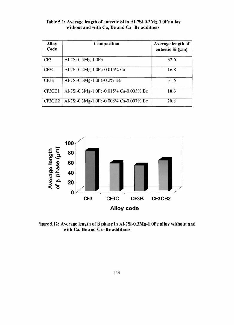
Table 5.1: Average length of eutectic Si in AI-7Si-O.3Mg-1.0Fe alloy without and with Ca, Be and Ca+Be additions
Alloy Code
CF3
CF3C
CF3B
CF3CBl
CF3CB2
-;; E C):::l. s::::Q) Q) - W Q) ca C)J: e Cl. Q)c:c..
~O
Composition
AI-7Si-0.3Mg-l.OFe
Al-7Si-0.3Mg-l.0Fe-0.0 15% Ca
AI-7Si-0.3Mg-l.OFe-0.2% Be
AI-7Si-0.3Mg-l.0Fe-0.0 15% Ca-0.005% Be
AI-7Si-0.3Mg-l.0Fe-0.008% Ca-0.007% Be
100
80
60
40
20
Average length of eutectic Si (J.Lm)
32.6
16.8
31.5
18.6
20.8
O+-------~------~------~------~ CFJ CF3C CF3B CF3CB2
Alloy code
Figure 5.12: Average length of ~ phase in AI-7Si-O.3Mg-1.0Fe alloy without and with Ca, Be and Ca+Be additions
123

Figure 5.13: SEM micrograph of AI-7Si-0.3Mg-0.8Fe alloy with Be (0.15%)+Mn (0.15%) addition
Figure 5.14: Typical microstructure of permanent mould cast AI-7Si-0.3Mg-0.8Fe alloy with Mn (0.3%)+Sr (0.04%) addition
124

Figure 5.15: EDS elemental X-ray mapping and elemental distribution of Chinese script Mn-Fe phase in AI-7Si-0.3Mg-0.8Fe alloy with Be (0.15%) + Mn (0.15%)
125
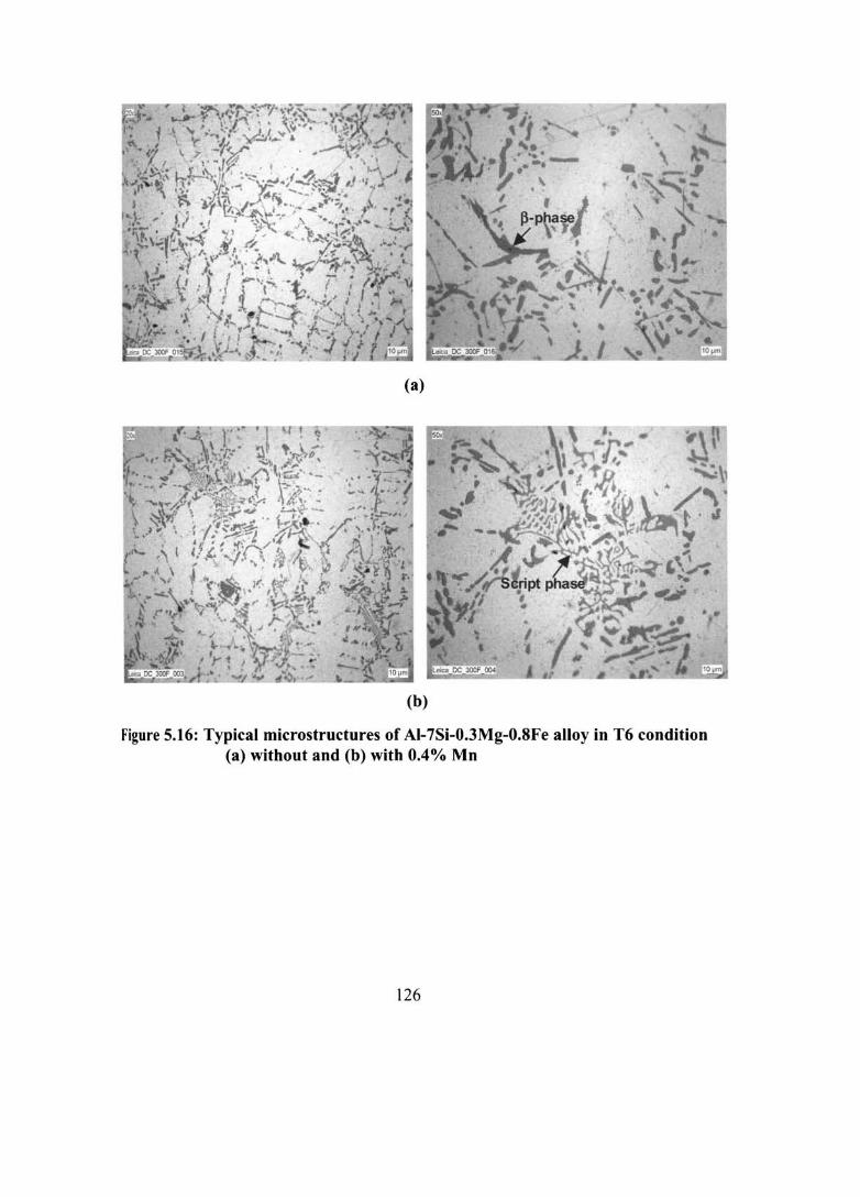
(a)
(b)
Figure 5.16: Typical microstructures of AI-7Si-0.3Mg-0.8Fe alloy in T6 condition (a) without and (b) with 0.4% Mn
126
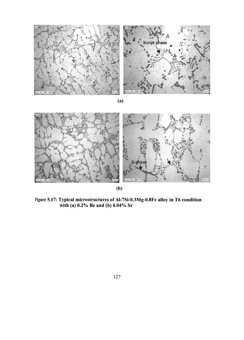
(a)
(b)
Figure 5.17: Typical microstructures of AI-7Si-0.3Mg-0.8Fe alloy in T6 condition with (a) 0.2% Be and (b) 0.04% Sr
127

5.3.2 Solidification Behaviour
5.3.2.1 Thermal Analysis
Figures 5.18-5.22 show the cooling curves and their first derivatives and the
microstructures (at the centre of the thermal analysis sample, where the thermocouple
tip was located) and Table 5.2 gives the alloys, thermal arrests and the phases formed
in AI-7Si-0.3Mg-0.8Fe alloy without and with Be (0.2%), Mn (0.4%), Ca (0.04%)
and Sr (0.04%) additions respectively. The first derivative is a measure of the
instantaneous cooling rate along the cooling curve and is used here to signal the
presence of minor slope changes on the curves. For each alloy sample, two cooling
curves were taken to check repeatability. Figure 5.18 shows first thermal arrest point
at 880.3 K, where the formation and growth of Al nuclei occur. After this arrest, the
temperature of the solidifying alloy continues to decrease. Primary Al dendrites grow
and the liquid is progressively enriched in Si and Fe. Second thermal arrest occurs at
858 K. This is caused by the latent heat fusion of the p-phase. Next arrest occurs at
845.9 K corresponding to the eutectic Si formation and growth. The final arrest point
occurs at 823.8 K when the M~Si phase is formed. On the other hand, the peak
corresponding to p Fe-intermetallic is completely absent with Be (0.2%) addition.
This shows that the p Fe phase has been changed to a.-(Be-Fe) phase as shown in the
microstructure. However, the peak corresponding to p Fe-intermetallic phase
formation is seen in the case ofMn, Ca and Sr additions. This is also evident from the
microstructures (Figures 5.19-5.22) showing both platelet and Chinese script phases
with Mn addition and refined platelet Fe intermetallics with Ca and Sr additions.
Further, Ca and Sr additions decrease the eutectic temperature compared to the
untreated alloy and the difference between the eutectic temperature of the untreated
and Ca and Sr added sample is 6.6 and 8.7 K respectively. This is due the
modification of eutectic Si by Ca and Sr additions to fine fibrous form as shown in the
microstructures.
5.3.2.2 Differential Thermal Analysis
Differential Thermal Analysis (DTA) has been carried out in Al-7Si-0.3Mg
O.8Fe, AI-7Si-0.3Mg-0.8Fe-0.2Be and Al-7Si-0.3Mg-0.6Fe-0.5Mn alloys at a heating
and cooling rate of 2° Klmin and the corresponding DT A curves are given in Figures
128
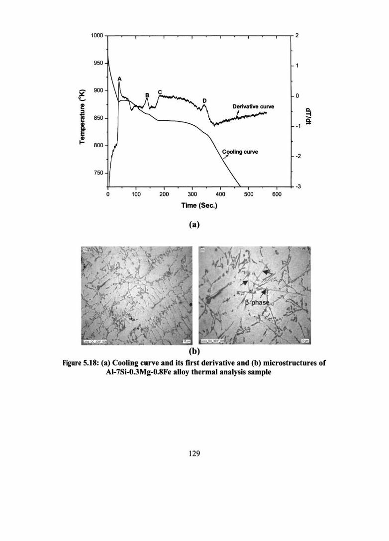
- 900 ~ 0 0 -! c. ::l - 850
-t f! -8. -1
a E CD ~ 800
-2
750
-3 0 100 200 300 400 500 600
Time (Sec.)
(a)
(b) Figure 5.18: (a) Cooling curve and its first derivative and (b) microstructures of
AI-7Si-O.3Mg-O.8Fe alloy thermal analysis sample
129

- 900 ~
0 -e c. ::::s -4 ... -e 850 a: !. E Q)
I- 800
o 100 200 300 400 500 600
Time (Sec.)
(a)
(b)
Figure 5.19: (a) Cooling curve and its first derivative and (b) microstructures of AI-7Si- O.3Mg-O.8Fe-O.2Be alloy thermal analysis sample
130

- 900 ~ 0 0 -! Q. ~ .. -I l! 850 -Q.
!. -1 -E Cl) I- 800
-2
750
-3 0 100 200 300 400 500 600
Time (Sec.)
(a)
(b)
Figure 5.20: (a) Cooling curve and its first derivative and (b) microstructures of AI-7Si-0.3Mg-0.8Fe-0.4Mn alloy thermal analysis sample
131
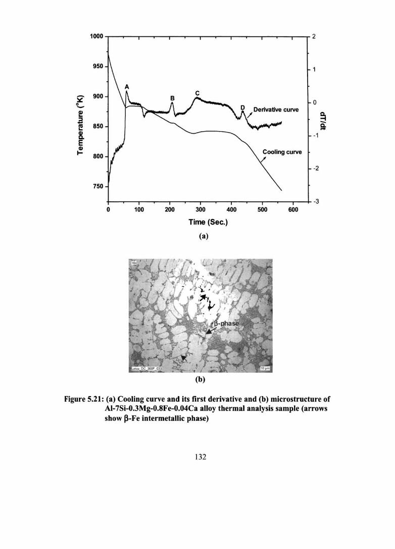
1000 ~--"'---r-"""T"'""-r---"-"""T"""--r----'-"""'T'"-~-"'---r-""T'" 2
950
- 900 :::.:: 0 0 -~ Q. ::l -t - -I!! 850 Q. -!. -1 E G,)
I- 800
-2
750
-3 0 100 200 300 400 500 600
Time (Sec.)
(a)
(b)
Figure 5.21: (a) Cooling curve and its first derivative and (b) microstructure of AI-7Si-O.3Mg-O.8Fe-O.04Ca alloy thermal analysis sample (arrows show p-Fe intermetallic phase)
132
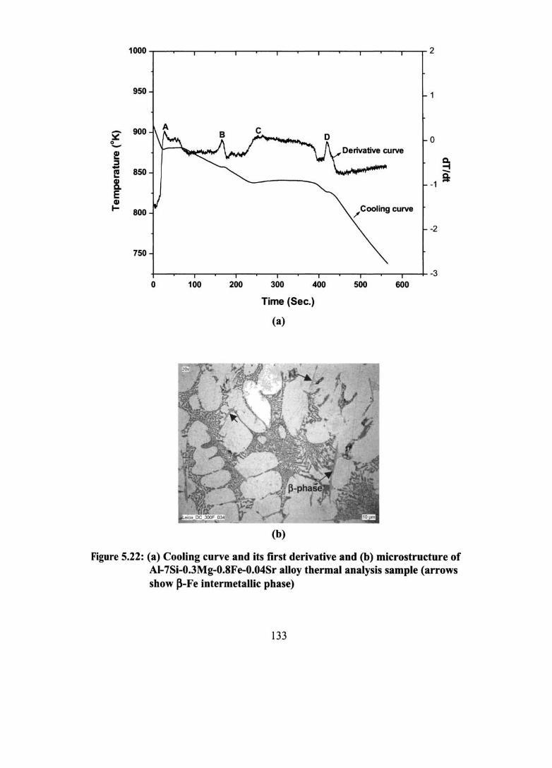
950
900 A -~ D 0 0 -! Cl. ::I .. -t I! 850 -8- -1
!* E CD I- 800 /Cooling curve
-2
750
-3 0 100 200 300 400 500 600
Time (Sec.)
(a)
(b)
Figure 5.22: (a) Cooling curve and its first derivative and (b) microstructure of AI-7Si-O.3Mg-O.8Fe-O.04Sr alloy thermal analysis sample (arrows show ~-Fe intermetallic phase)
133

Table 5.2: Alloys, thermal arrests and the phases formed in AI-7Si-O.3Mg-O.8Fe alloy without and with Be, Mn, Ca and Sr additions
Alloy Thermal arrests Phases formed
Peak Temperature ('1q
AI-7Si-0.3Mg-0.8Fe A 880.3 Primary a-AI B 858.0 Iron intermetallics C 845.9 Eutectic Si D 823.8 M~Si phase
AI-7Si- 0.3Mg-0.8Fe-0.2Be A 880.7 Primary a-AI B 838.1 Eutectic Si C 823.7 M~Si phase
1A1-7Si-0.3Mg-0.8Fe-0.4Mn A 879.6 Primary a-AI B 856.5 Iron intermetallics C 845.8 Eutectic Si 0 823.8 M~Si phase
1A1-7Si-0.3Mg-0.8Fe-0.04Ca A 882.1 Primary a-AI B 855.9 Iron intermetallics C 839.3 Eutectic Si 0 826.4 M~Si phase
1A1-7Si- 0.3Mg-0.8Fe-0.04Sr A 879.3 Primary a-AI B 857.2 Iron intermetallics C 837.2 Eutectic Si 0 826.7 M~Si phase
134

0 Heating at 2°Klmin.
-2 ./
-4 Onset 833.8 Peak 836.0 _ Onset 869.3
- Peak 888.1 > :::1. -6 -~ 0 I;: -8 ..-ca Q)
::I: -10
Onset 842.1 --12 Peak 852.6
-14
800 850 900 950
Temperature tK)
(a)
6
Cooling at 2°K/min. 4
.V\j' Onset 846.7 2 - Peak 842.8
:> 0 Onset 885.1 -:::1. Peak 883.0 -~ -2 Onset 826.2 0 Peak 823.3 ;;: ..- " ca -4 Q)
J:
-6
-8
-10 800 850 900 950
Temperature (oK)
(b)
Figure 5.23: DTA curves of AI-7Si-O.3Mg-O.8Fe alloy (a) Heating and (b) Cooling at 2°Klmin.
135

o
-5
~ -~ -10 o ;;::
'tU Cl)
::I: -15
-20
35
30 -
25 -
20 -
~ 15 -
~ 10 0 I;: .... ca 5 CD l:
0
-5
-10
Heating at 2°K/min.
Onset 876.4 Peak 878.4 ,---------J
850
\
_Onset 846.2 Peak 852.4
Onset 882.1 Peak 885.4
900
Temperature (oK)
(a)
950
Cooling at 2°K/min
Onset 841.3 Peak 837.1 -
--~) LT-
_Onset 870.6 Peak 870.1
.-·6 ~ .... ..
Onset 862.5;-------___ ~ -Peak 858.8
800 850 900 950
Temperature (oK)
(b)
Figure 5.24: DTA curves of AI-7Si-0.3Mg-0.8Fe alloy with 0.2% Be addition (a) Heating and (b) Cooling at2°Klmin.
136
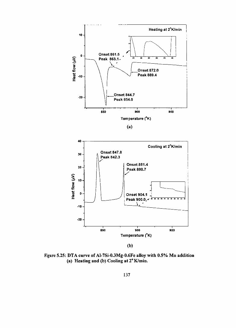
~ ~ 0 it: .. ra Cl)
J:
~ ~ 0
r;:: .. ra Cl)
J:
10
0
-10
-20
Heating at 2°Klmin
Onset861.5 • ;1\ . ~1.1 Peak 863.1, "'..............
850
\, ,
_Onset 844.7 Peak 854.0
Onset 872.0 Peak 889.4
900
Temperature (oK)
(a)
950
~,---------------------------------------,
30
20
10 -
0
---.J -10
-20
Onset 847.8 Peak 842.3
,/
Onset 881.4 Peak 880.7
/"
Cooling at 2DKlmin
On.~904.1 ~ S~ Peak 900.0, ~ - - - - - - - - - - -
\ ..
850 900
Temperature tK) 950
(b)
Figure 5.25: DTA curve of AI-7Si-0.3Mg-0.6Fe alloy with 0.5% Mn addition (a) Heating and (b) Cooling at 20 Klmin.
137

5.23-5.25. The peak corresponding to platelet Fe intermetallic could not be detected
since it merges with the eutectic Si reaction as shown in the cooling curve (Figure
5.23). It is seen from the Figure 5.24 that the temperature of Be-Fe phase dissolution
(heating curve) and the precipitation (cooling curve) are higher than the peak
corresponding to p-Fe intermetallic phase formation (858 K from thermal analysis).
As a result, the amount of free iron available to precipitate in the form of p-AIsFeSi is
diminished. This is supported from the microstructural observation of the replacement
of platelet Fe intermetallics by Chinese script phases. Similarly, the peak at 863 K
(heating curve) in Figure 5.25 corresponds to Chinese script Mn-Fe-intermetallic
phase reaction. The observation of sludge formation at higher Mn (0.5%) addition in
the microstructure is supported from the appearance of a peak at 900 K (cooling
curve).
5.3.3 Physical characteristics
5.3.3.1 Porosity
Table 5.3 shows the effect of Ca, Mn and Ca + Mn on the porosity and
electrical conductivity of AI-7Si-0.3Mg-0.6Fe alloy. It is seen that % porosity is
increased with Ca (0.05%) addition compared to the untreated and other additions
studied. The % porosity is lower with Mn followed by Ca + Mn additions. This may
be due to the morphological change of large platelet Fe-intermetallic compounds to
star like, Chinese script and other compact shapes. This result is in accordance with
the work of Samuel et al l9S on the effect of Be, Mn, Cr and Sr on 319 (AI-6.2Si-
3.7Cu) alloy, which has shown that the contours of the script phase facilitate the
filling up of the liquid metal in between the dendrite arms of the phase (compared to
the blocking action of the p-needleslplatelets) and thereby reducing the amount of
porosity.
5.3.3.2 Electrical conductivity
The electrical conductivity of Ca added samples are higher than those of the
untreated, Mn and Ca+Mn added samples (Table 5.3). This is due to the modification
of eutectic Si by Ca addition to fibrous form, which allows easier flow of electrons
compared to the platelet morphology.
138
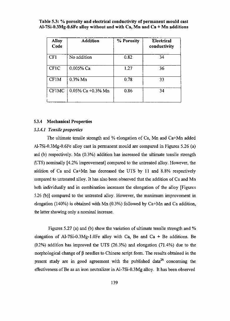
Table 5.3: % porosity and electrical conductivity of permanent mould cast AI-7Si-O.3Mg-O.6Fe alloy without and with Ca, Mn and Ca + Mn additions
Alloy Addition Code
CFl No addition
CFIC 0.005% Ca
CFIM 0.3%Mn
CFIMC 0.05% Ca +0.3% Mn
5.3.4 Mechanical Properties
5.3.4.1 Tensile properties
% Porosity Electrical conductivity
0.82 34
1.27 36
0.78 33
0.86 34
The ultimate tensile strength and % elongation of Ca, Mn and Ca+Mn added
AI-7Si-0.3Mg-0.6Fe alloy cast in pennanent mould are compared in Figures 5.26 (a)
and (b) respectively. Mn (0.3%) addition has increased the ultimate tensile strength
(UrS) nominally [4.2% improvement] compared to the untreated alloy. However, the
addition of Ca and Ca+Mn has decreased the UTS by 11 and 8.8% respectively
compared to untreated alloy. It has also been observed that the addition of Ca and Mn
both individually and in combination increases the elongation of the alloy [Figures
5.26 (b)] compared to the untreated alloy. However, the maximum improvement in
elongation (140%) is obtained with Mn (0.3%) followed by Ca+Mn and Ca addition,
the latter showing only a nominal increase.
Figures 5.27 (a) and (b) show the variation of ultimate tensile strength and %
elongation of Al-7Si-0.3Mg-l.0Fe alloy with Ca, Be and Ca + Be additions. Be
(0.2%) addition has improved the UTS (26.3%) and elongation (71.4%) due to the
morphological change of P needles to Chinese script fonn. The results obtained in the
present study are in good agreement with the published data26 concerning the
effectiveness of Be as an iron neutralizer in Al-7Si-0.3Mg alloy. It has been observed
139

400
-~ 300 :E -.. tJ)
I- 200 ~
100 +-----~------~------~----~
3
c: o ; 2 ca C) c: o
ijj 1 ~
CF1 CF1C CF1M
Alloy Code
(a)
CF1MC
O +-------~------~------~------~
CF1 CF1C CF1M CF1MC
Alloy Code
(b)
CF I: AI-7Si-0.3Mg-0.6Fe CFIC: AI-7Si-0.3Mg- 0.6Fe +0.05% Ca CFIM: AI-7Si-0.3Mg-0.6Fe +0.3%Mn CFIMC: AI-7Si-0.3Mg- 0.6Fe +0.3%Mn+0.05% Ca
Figure 5.26: Effect of Ca, Mn and Ca+Mn additions on the (a) UTS and (b)% elongation of AI-7Si-O.3Mg-O.6Fe alloy cast in permanent mould
140

300
250 -ca Q.
!. 200 tJ) .... ::J
c 0 -ca Cl c 0 [j ~ 0
150
100+-----~--~----~----~----~ CF3
3
2
1
CF3C CF3B CF3CB1 CF3CB2
Alloy Code
(a)
O +-----~------~----~------~----~ CF3 CF3C CF3B CF3CB1 CF3CB2
Alloy code
(b)
CF3: AI-7S-0.3Mg-1.0Fe CF3C: AI-7S-0.3Mg-1.0Fe +0.015% Ca CF3B: AI-7S-0.3Mg-1.0Fe +0.2% Be CF3CB1: AI-7S-0.3Mg-1.0Fe +0.015% Ca+0.015% Be CF3CB2: AI-7S-0.3Mg-1.0Fe +0.008% Ca + 0.007% Be
Figure 5.27: Effect of Ca, Be and Ca+Be additions on the (a) UTS and (b) % elongation of AI-7Si-O.3Mg-1.0Fe alloy cast in permanent mould
141

that a trace amount of Be addition to AI-7Si-0.3Mg-1.0Fe-0.015% Ca
alloy improves both the UTS and elongation compared to Al-7Si-0.3Mg-l.0Fe and
AI-7Si-0.3Mg-1.0Fe-0.015Ca alloys. The maximum improvement in tensile strength
(34.5%) is obtained with Ca (0.008%)+Be (0.007%) addition. However, % elongation
is low compared to the Be added alloy. This is due to insufficient amount of Ca to
reduce the length of ~ needles completely. Hence, a higher amount of Ca with trace
Be may give the best combination of tensile properties.
The ultimate tensile strength and % elongation of Al-7Si-0.3Mg-0.8Fe alloy
treated with Be, Ca, Mn and Sr individually or in combination and cast in permanent
mould are shown in Figures 5.28 (a) and (b) respectively. It has been observed that all
additions except Ca, Sr and Mn increase the UTS compared to the untreated alloy.
The highest improvement in UTS has been observed in the combined addition of Be
(0.15%) and Mn (0.15%) to AI-7Si-0.3Mg-0.8Fe alloy. On the other hand, Ca
(0.04%), Sr (0.04%) and Mn (0.4%) additions have reduced the UTS by 9.2, 5.3 and
8.6% respectively compared to that of untreated AI-7Si-0.3Mg-0.8Fe alloy. It has also
been observed that the addition of Be, Ca, Sr and Mn both individually and in
combination. increases the % elongation of the alloy [Figures 5.28 (b)] compared to
the untreated alloy. This is due to the morphological change of platelet Fe
intermetallics to Chinese script form with Be and Mn additions and the refinement of
platelet Fe phases with Ca and Sr additions respectively. Addition of Mn (0.3%) to
Al-7Si-0.3Mg-0.8Fe-0.04% Ca and AI-7Si-0.3Mg-0.8Fe-0.04% Sr alloys leads to 75
and 167% improvement in elongation respectively compared to individual addition of
Ca and Sr.
Be (0.2%) addition has shown significant improvement in elongation (125%).
It is interesting to note that trace amount of Be (0.005%) with Ca and Sr (0.04%) has
improved the UTS (2 and 5.5% respectively) and elongation (100 and 167%
respectively) compared to the untreated and Ca and Sr alone added alloys.
5.3.4.2 Impact Strength
Figure 5.29 shows the impact strength of Al-7Si-0.3Mg-0.6Fe alloy with and
without Ca, Mn and Ca+Mn additions. As reported in the previous chapter, impact
142

380
340
ca 300 D.. :E 260
~
Cl) 220 I-::l 180
140
100 A B C 0 E F G H J
Alloy Code (a)
£: 0 2 .. ca C)
1.5 £: ..2 w 1 ~ 0
0.5
0 A B C D E F G H J
Alloy Code
(b)
A: AI-7Si-0.3Mg-0.8Fe B: AI-7Si-0.3Mg-0.8Fe +0.2% Be C: AI-7Si-0.3Mg-0.8Fe +0.04% Ca D: AI-7Si-0.3Mg-0.8Fe + 0.04% Sr E: AI-7Si-0.3Mg-0.8Fe +0.4% Mn F: AI-7Si-0.3Mg-0.8Fe +0.3% Mn+ 0.04% Ca G: AI-7Si-0.3Mg-0.8Fe + 0.3% Mn+0.04% Sr H: AI-7Si-0.3Mg-0.8Fe + 0.005% Be+0.04% Ca I: AI-7Si-0.3Mg-0.8Fe + 0.005% Be+ 0.04% Sr
J: AI-7Si-0.3Mg-0.8Fe +0.15% Be+0.15% Mn
Figure 5.28: Effect of Be, Mn, Sr and Ca individually and in combination on the (a) UTS and (b) % elongation of AI-7Si-O.3Mg-O.8Fe alloy
143
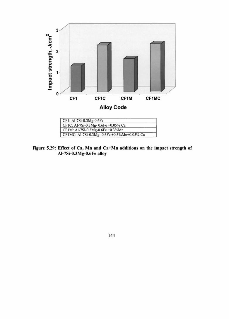
3 N
E (,) -.., .c 2 -C) s: ! -tn
1 -(,) ca c. E
o¥---------~-------,--------~--------~
CF1 CF1C CF1M CF1MC
Alloy Code
CFl: AI-7Si-0.3Mg-0.6Fe CFIC: AI-7Si-0.3Mg- 0.6Fe +0.05% Ca CFIM: AI-7Si-0.3Mg-0.6Fe +O.3%Mn CFIMC: AI-7Si-0.3Mg- 0.6Fe +0.3%Mn+0.05% Ca
Figure 5.29: Effect of Ca, Mn and Ca+Mn additions on the impact strength of AI-7Si-O.3Mg-O.6Fe alloy
144

strength has been greatly improved (80%) by Ca addition. However, only 27%
improvement in impact strength has been observed in Mn added alloy. Ca+Mn
addition shows 85% improvement. Further, the microstructural features observed in
the fracto graphs of impact tested alloys [Figures 5.30 (a-d)] support these results. Ca
added alloy shows more dimples, a characteristic of ductile fracture [Figure 5 .31 (b)].
On the other hand, fracto graph of Mn added alloy [Figure 5.31 (c)] shows the
presence of a large number of cleavage fractured surface typical of a brittle failure.
The effect of Be, Mn, Sr and Ca addition individually and in combination on
the impact strength of T6 heat-treated AI-7Si-0.3Mg-0.8Fe alloy is shown in Figure
5.31. It has been found that all additions except Mn improve the impact strength
compared to the untreated alloy. However, combined addition of Mn with Ca, Sr and
Be improves the impact strength.
5.4 DISCUSSION
The large size of B-AIsFeSi platelet observed in the untreated alloys indicates
that it must have formed at a higher temperature, i.e, as a pre-eutectic reaction
(providing a.longer time for its growth). On the other hand, the much smaller sjze of
the B-platelets observed indicates that they are very likely the products of a co
eutectic reaction. It has been reported 144,200,201 that unlike the Si eutectic temperature,
which is only marginally affected by variations in cooling rate, the B-phase start
temperature decreases with decreasing iron content, increasing cooling rate and
increasing melt superheat until it eventually merges with the Si eutectic temperature.
Though the B-phase continues to crystallize until the end of the silicon eutectic
reaction, the length of the primary B-phase needles greatly depends on the time
interval between the B-phase start temperature and the silicon eutectic temperature.
With decreasing B-phase start temperature, the B-phase growth time and therefore the
length and volume fraction of this phase decrease until the B-phase start temperature
merges with the silicon eutectic temperature.
It has been observed that the eutectic Si nucleates on the surface of the
~-platelets [Figure 5.1 (b)]. This is supported from the work of Taylor et a1.272 It has
145

Figure 5.30: Fractographs of impact tested AI-7Si- 0.3Mg- 0.6Fe alloy (a) without and with (b) 0.05% Ca (c) 0.3%Mn and (d) 0.3% Mn+0.05% Ca
146

2.5
N
E CJ 2 -..,
.J:. - 1.5 C) C
~ -Cl) -CJ ca 0.5 Q. E
0 A B C D E F G H J
Alloy Code
A: AI-7Si-0.3Mg-0.8Fe B: AI-7Si-0.3Mg-0.8Fe +0.2% Be C: AI-7Si-0.3Mg-0.8Fe +0.04% Ca D: AI-7Si-0.3Mg-0.8Fe + 0.04% Sf E: Al-7Si-0.3Mg-0.8Fe +0.4% Mn F: AI-7Si-0.3Mg-0.8Fe +0.3% Mn+ 0.04% Ca G: AI-7Si-0.3Mg-0.8Fe + 0.3% Mn+0.04% Sf H: AI-7Si-0.3Mg-0.8Fe + 0.005% Be+0.04% Ca I: AI-7Si-0.3Mg-0.8Fe + 0.005% Be+ 0.04% Sf
1: AI-7Si-0.3Mg-0.8Fe +0.15% Be+0.15% Mn
Figure 5.31: Effect of Be, Mn, Sr and Ca individually and in combination on the impact strength of AI-7Si-O.3Mg-O.8Fe alloy
147

been reported that the Si particles are often observed to grow from multiple locations
along a single ~-platelet. For eutectic Si to nucleate and grow on the ~-platelets, the
latter must form and present prior to the former. This is the case for the platelets
that form as either a primary ~-phase or as binary ~-phase (a component of the AI-~
AIsFeSi binary eutectic). Such platelets are well developed by the time the ternary
eutectic Si begins to grow. This has been confirmed by the appearance of a peak at
858 K in Figure 5.18 corresponding to ~-platelets formation.
Addition of Mn changes the morphology of platelet Fe intermetallic to
Chinese script. This is because of the replacement of Mn by Fe, which can substitute
each other, being transitional elements. However in the case of 0.5% Mn addition,
agglomeration of the script and star like particles takes place [Figure 5.2 (b)]. In order
to obtain the crystallization of the iron compound in the Chinese script form and
avoid the needle like and polyhedral crystal morphology, a certain critical ratio of
iron: manganese is required and this ratio depends on the cooling rate. Bakerud et
al244 have clearly explained the solidification sequence (Figure 2.13) with Mn addition
in Al-7Si-0.3Mg alloy. According to Mondolfo,8 (Fe,Mn)Al6 is the first llhase to form
in the AI-Fe-Mn-Si system, which encompasses many commercial alloys. In many
alloys, (Fe,Mn)AI6 reacts peritectically with the liquid to form (FeMn)3ShAhs. The
rate of peritectic transformation depends on the equilibrium diagram and kinetic
factors?80-283
Be (0.2%) has changed the morphology of platelet Fe compound to Chinese
script and fine globules. Both Mn and Be additions lead to the precipitation of either
coarse or fme Chinese script form of intermetallic phase with Fe at slow (thermal
analysis sample, cooling rate 1.50 Klmin) and fast cooling rates (permanent mould)
respectively. It has also been observed in the present work that the Chinese script
phases with Be addition forms only inside the a-AI at slow cooling rate and both
inside the a-AI and in the interdendritic areas at high cooling rates. Murali et al210
have reported that in the case Be (0.27%) added sand cast AI-7Si-0.3Mg alloy, the
Be-Fe phase is formed inside the a-AI, which is probably the result of a peritectic
reaction. It has been observed from the DTA curves (Figures 5.24 and 5.25) that the
Be-Fe and Mn-Fe phases precipitate at temperatures much higher than the formation
148

temperature of the ~-phase. As a result, the amount of free iron available to
precipitate in the form of ~-AI5FeSi is diminished leading to the formation of Chinese
script phase.
Be (0.2%) addition has significantly . improved the tensile and impact
properties. This is due to the morphological change of P needles to Chinese script
form. This has been further confirmed from the cooling curve of AI-7Si-0.3Mg-0.8Fe-
0.2Be alloy showing the absence of a peak corresponding to ~-Fe intermetallic
compared to the cooling curve without Be addition (Figures 5.18 and 5.19). The
microstructures of Mn and Be added alloys in the T6 treated condition show the
persistence of Chinese script phases. Further, it has been reported277 that a-AIFeMnSi
particles have quite perfect crystals and hence the dissolution process is hindered by
the lack of defects.
The improvement in elongation and impact strength with Sr addition is due to
the fragmentation of the platelet Fe intermetallics and modification of the eutectic Si.
This observation is in accordance with the work of Samuel et al195 on Sr addition to
AI-Si-Cu (319) alloy. The fragmentation of platelet Fe-intermetallic phase is clearly
explained in the previous chapter.
It has been found that Mn addition improves the tensile properties. On the
other hand, impact strength is not significantly improved. However, Mn in
combination with Ca, Sr and Be improves the impact strength significantly. This is
due to the modification of the eutectic Si from acicular to fibrous form. The most
important observation in the present work is the attainment of the best combination of
tensile and impact properties by Ca+Mn, Sr+Mn and Be+Mn additions to AI-7Si-
0.3Mg-xFe alloys. Similarly, combined addition of a trace amount of Be (0.005%) to
Ca and Sr improves the tensile properties significantly. This is due the fact that Be in
trace amount in AI-Si alloys preferentially oxidizes forming BeO on the surface of the
casting, cleans the melt surface and reduces gas pick up (and hence porosity) and Mg
loss making Mg available for forming the required volume of M~Si for
strengthening.250
149

5.5 SUMMARY
1. Mn (0.3%) addition to AI-7Si-0.3Mg-xFe alloy changes the morphology of
platelet iron phase to script fonn leading to significant improvement in tensile
properties. However, there is no significant improvement in impact strength.
2. Be (0.2%) changes the platelet morphology of iron phase to Chinese script
fonn, which are seen only inside the a-AI in slow cooling (sand cast), both in
the interdendritic as well as inside the a-AI in fast cooling (pennanent mould
casting). This morphological change is responsible for the significant
improvement in both the tensile and impact properties.
3. Combined additions of Ca + Mn, Be + Mn and Sr + Mn lead to improvement
in both tensile and impact properties compared to individual additions and a
synergistic effect of both the elements is achieved.
4. A trace amount of Be (0.005%) addition to Ca and Sr leads to superior tensile
properties compared to Ca and Sr additions alone.
150
CHAPTER 6
CONCLUSIONS
In the present investigation, the dual beneficial effects of Ca viz., modification
and Fe-neutralization, comparison of the effects of Ca and Sr with common Fe
neutralizers (Be and Mn) and the interaction of Be, Mn, Sr and Ca in a commercially
important cast AI-7Si-0.3Mg alloy have been studied. The castings have been
characterized with respect to their microstructure, % porosity and electrical
conductivity, solidification behaviour and mechanical properties. The major
observations and the conclusions drawn are given under each chapter. This chapter
summarizes all of them together as well as highlights the significant contributions of
this thesis to the knowledge and the avenues for future work.
1. Calcium modifies the platelet eutectic Si in AI-7Si-0.3Mg alloy to fibrous form.
The ~ptimum level of Ca required for modification so as to get the best
mechanical properties lies in the range 0.01-0.02%.
2. Porosity of Ca (0.02%) added sample is lower than that treated with the well
known modifier viz., Sr. The properties obtained with Ca (0.02%) addition are at
par with those obtained with Sr (0.02%) addition.
3. Like Sr, higher amount of Ca also leads to the formation of higher porosity and
AI-Ca-Si intermetallics.
4. Ca addition to AI-7Si-0.3Mg-xFe alloy modifies the eutectic Si and refines the
long platelet ~-Fe phases. The proposed mechanism of Fe-neutralization by Ca is
the destabilization of the ~-platelets and fragmentation of the long ~-platelets into
smaller ones.
5. A low amount of Ca (0.005%) has reduced the porosity of the alloy probably due
to the trapping of hydrogen as calcium hydride.

6. Higher Ca levels lead to faster pickup of hydrogen probably due to the rupture of
the protective Ah03 oxide film by the Ca containing oxide film.
7. Electrical conductivity is increased with Ca addition due to the change in eutectic
Si morphology from acicular to fibrous form.
8. Ca addition has improved the % elongation and impact strength of AI-7Si-0.3Mg
xFe alloys significantly.
9. A high amount of Ca (0.05%) addition reduces the size of the platelet Fe
intermetallics to very fine form. A maximum improvement in impact strength has
been achieved by 0.05% Ca addition to AI-7Si-0.3Mg-0.6Fe alloy. However, Ca
at this level has led to the precipitation of AhCaSi2 intermetallics and higher
porosity in the castings.
10. An empirical analysis carried out for comparing the results of the present work
with those of the other researchers on the effect of increasing iron content on
UTS and % elongation of AI-Si-Mg and AI-Si-Cu alloys has shown a linear and
an inverse first order polynomial relationships respectively.
11. Mn (0.3-0.5%) addition to AI-7Si-0.3Mg-xFe alloy changes the morphology of
platelet iron phase to script form. This has led to a significant improvement in
tensile properties. However, there is no significant improvement in impact
strength.
12. Be (0.2%) addition to Al-7Si-0.3Mg-xFe alloy changes the platelet morphology
of iron phase to Chinese script form. This morphological change has resulted in
significant improvement in both the tensile and impact properties.
13. Combined additions of Ca + Mn, Sr + Mn and Be + Mn have yielded
improvement in both tensile and impact properties compared to individual
additions.
14. A trace amount of Be (0.005%) addition to Ca and Sr leads to superior tensile
properties compared to Ca and Sr additions alone.
152
6.1 SIGNIFICANT CONTRIBUTIONS OF THE PRESENT INVESTIGATION TO THE KNOWLEDGE
1. Dual role of calcium viz., Modification and Fe-neutralization leading to improved
elongation and impact properties in AI-7Si-0.3Mg-xFe alloys.
2. The properties obtained with Ca (0.02%) modification are at par with those
obtained with the well known modifier viz., Sr (0.02%).
3. The optimum level of Ca in high Fe containing Al-7Si-0.3Mg alloy with respect
to its fragmentation effect on the p-Fe intermetallic phase lies in the range 0.03-
0.04%.
4. A trace amount of Be (0.005%) addition to Ca and Sr in Al-7Si-0.3Mg-xFe alloy
leads to superior tensile properties compared to Ca and Sr additions alone.
5. The limitation on the impact properties of AI-7Si-0.3Mg-xFe alloy by Mn
addition has been overcome by the combined addition of Mn with Ca and/or Sr
and a synergistic effect of both the elements is achieved.
6. Judicious combinations of the iron neutralizers studied can pave the way for
increased utilization of secondary or recycled aluminium alloys, requiring
mlmmum energy.
6.2 AVENUES FOR FUTURE WORK
1. Low amount of Ca (0.005%) reduced the porosity of the alloy probably due to the
trapping of hydrogen as calcium hydride. However, further work is required to
confirm such a hypothesis.
2. Understanding of the three-dimensional morphology of iron-containing
intermetallics using modelling techniques.
3. Processing of Aluminium Matrix Composites using Ca as wetting promoter and
Fe-neutralizer by liquid stir casting technique where lot of Fe will be introduced
through the steel rod used for stirring.
153

REFERENCES
1. Alan B. Deross: "Alwninwn Casting Technology", p.31, American
FOWldrymen's Society, Inc., Des Plaines, Illinois.
2. John. E. Hatch: 'Alwninwn: Properties and Physical Metallurgy' , 200-211;
140: 1984, American Society for Metals, Metals Park, Ohio.
3. www.mineralresourcesforum.org
4. J.A. Taylor: Int. J. Cast Metals, 1995,8(4),225-252.
5. B. Closset and J.E. Gruzleski: AFS Trans. 1982,90,453-464.
6. A.M. Samuel, A. Pennors, C. Villeneuve and F.H. Samuel: Int. J. Cast Metal
Res., 2000,13,231-253.
7. V.P. Itkin, C.B. Alcock, PJ. Van Ekeren and H.A.J. Oonk: 'Binary Alloy
phase Diagrams', 2nd edn, 2.42; 1992, Ohio, ASM Materials Park.
8. L.F. Mondolfo: 'Alwninwn Alloys: Structure and Properties', 1976, London,
Butterworths.
9. Teng-Shih and Fang-Shea Shih: Int. J. Cast Met. Res., 1998, 10,273-
10. A.M. Samuel, P. Quellet, F.H. Samuel and H.W. Doty: AFS Trans., 1997,
105,951-962.
11. H. De La Sablonmere and t .H. Sam\lel: Int. 1. Cast Met. Res., \996,9, 19S
12. P. Quellet, F.H. Samuel, D. Gloria and S. Valtierra: Int. J. Cast Met. Res.,
1997,10,67.
13. http://www.world-alwniniwn.org
14. WWW. Wleptie.org/outreach/wssd/contributionsl sector_reports
15. F. Paray, B. KulWlk and J.E. Gruzleski: IntJ.Cast Metals Res., 2000, 13,
17-37.
16. G.K. Sigworth, S. Shivkwnar and D. Apelian: AFS Trans. 1989,97,811-824.
154

17. M. Tsukuda, M. Harada, T. Suziki and S. Kokie: J. Jpn. Inst. Light Metals
1978,2S(3), 109.
18. R.C. Harris, S. Lipson and H. Rosenthal: AFS Trans. 1956,64,470.
19. W.A. Bailey: Foundry, May 1964, 54.
20. J. Sulinski: AFS Trans., 1967, 75, 548-566.
21. T. Gaspar, "Effect of trace elements in superalloys", Metals and- Ceramics
Information Center, No.145, Mar.(1985).
22. G.J. Simensen,"Quality Assurance of DC-Casting of Aluminium",
Continuous Casting: Melting -Casting-Control, DGM Informations
Gessellschaft, pp.305-318 (1986).
23. B.L. Tuttle, A. Keslinke, D. Twarog and E. Daniels: AFS Trans., 1989, 97,
889-902.
24. Shu-Zu Lu and A. Hellawell: Metall. Trans., 1987, lSA(lO), 1721-1733.
25. B.S. Murthy, S.A. Kori and M. Chakraborty: Int. Mater. Rev., 2002, 47(1),
3-29.
26. S. Murali, K.S. Raman and K.S.S. Murthy: Int. J. Cast Metals, 1994, 6,
189-1"98.
27. Y. Kobayashi, M. Niinomi, M. Yamoka and Y. Shimomara, J. Jpn. Inst.
Light Met. 1993,43,472.
28. C.J. Machovec, G.E. Byezynski, J.W. Zindel and LA. Godlewski: AFS
Trans., 2000, lOS, 439-444.
29. C.R. Loper, Jr and 1.-1. Cho: AFS Trans., 2000, 108,667-672.
30. W. Martin: US Pat. No.3, 128, 176, Apr.7, 1964.
31. J. Glownia, P. Bolechata, and Z. Kutig: Krzepiece Met. Stapon 1979, 1, 70-8.
32. G. Bemd and J. Helmut: Stoeperitidende 1980,46(6), 168-9,171-3.
33. G. Bemd and J. Helmut: Giesserei 1980,67(1), 8-l3 (Ger)
34. Y. Tsumura, A. Sakukibaru, K. Toyada and M. Ishikawa: J. Japan, Inst.
Light Metals, 1980,30,239-245.
155

35. R. Cook: Scandinavian Metallurgical Co.: 19; 1998, Wimbledon Hill Road,
London, SW19 7LZ, UK.
36. B.P. Christian, E.-J. Friedrich and K. Thomas: Giessereiforchung 1982, 34
(3),111-117 (Ger.)
37. A.G. Cooper Gwyer and H.W. Lewis Phillips: US Pat. No.l, 657, 389,
Jan.24, 1928.
38. S. Baliktay and S. Honer: Giesserei, 1982,69,397-402 (in German)
39. T. Kobayashi, H.J. Kim, and M. Niinomi: Materials Science and
Technology, 1997, 13 (6), 497-502.
40. T. Kobayashi: in Proc. Conf. '6th International Conference on Alwninwn
Alloys', Toyohashi, Japan, 5-10; 1998.
41. T. Kobayashi, T. Ito, Q. Yao and N. Fatahalla: Materials Science and
Technology, 1999,15 (6), 1037-1043.
42. H.J. Kim, T. Kobayashi and T. Ito: Materials Science Forwn, 1996,217-222,
1395-1400.
43. P.V. Bonsignore and EJ. Daniels: Modem casting, 1991,81(5),28-29.
44. P.V. Bonsignore and E.J. Daniels: in Proc. Conf. 'Light Metals 1995', 12-16;
1995, Warrendale, PA, Minerals, Metals and Materials Society/AIME.
45. G. Piatti: J. Mater. Sci. 1983,18(8),2471-83 (Eng).
46. D. Moore and L.R. Morris: Alcan Research and Development Ltd., Can. CA
1, 113,282.
47. D. Moore and L.R. Morris: Jpn. Kokai Tokyo Koho 78, 125,918.
48. Wu Qingling, Ma Higsheng and Ma Longxiang: Dongbei Gongxueyuan
Xuebao 1984,38,37-42 (ch).
49. V.K. Portnoi and V.M. Henko: Izv. Vyssh. Uchebn. Zaved, Tsevetn. Metall.
1984, (3), 70-4 (Russ).
50. Liquan Ma and Zhen-Lun Song: Scripta Mater. 1998,39(11), 1523- 1528.
51. S. Akiyama, H. Ueno, K. Koji, A. Imagawa, S. Nagata, K. Morimoto,
T. Nishikawa and M. Itoh: US Pat. No. 4, 713, 277, Dec 1987.
156
52. Y. Sugimura, J. Meyer, M.Y. He, H. Bart-Smith, J. Grenstedt and
A.G. Evans: Acta Mater., 1997,45(12),5245-5259.
53. Zhen-Lun Song, Liquan Ma, Zhao-Jin Wu and De-Ping He: J. Mater. Sci.
2000,35, 15-20.
54. W. Keng, Q. Wei, C. Shaojun and L. Yixian: Zhongguo Youse Jinshu
Xuebao 1998, 8 (Suppl.l), 80-85 (Ch).
55. Sh. Chu and Q. Niu, K. Wu: Huagong Yejin (Eng.Chem.Metall.), 1998,
19(3),260-265 (in Chinese).
56. A. Kawabe, A. Oshida, T. Kobayashi and H. Toda: Keikinzoku 1999,49(4),
149-154 (Japan).
57. T. Hikosaka, K.M. Ki and N.I. Kawamoto: Alutopica (Jpn.) Feb. 1988,
18(2),56-65.
58. C.H. Chiu and C.F. Yang: Chukung (J. Chin. Foundrymen's Assoc.), Dec.
1999,25(4),22-35 (in Chinese).
59. J. Choh, Z. Ebihara and T. Oki: J. Jpn. Inst. Light Met., Oct. 1988, 38(10),
600-607.
60. T. N~ai, Y. Osava and M. Kikuchi: Trans. Jpn. Foundrymen's Soc. Apr.
1986, 5, 29-32.
61. Hitachi Chemical Co.: CA, 98 (10): 165566a
62. Agency Of Industrial Sciences and Technology: Jpn. Kokai Tokyo Koho JP
81, 141,960.
63. K. Hirohiko, K. Toshitake and N. Hideo: Jpn. Kokai Tokyo Koho JP 10 121,
167(Japan).
64. S. Towato, S. Yamada and T. Ohwaki: Trans. Jpn. Inst. Met., 1985, 26(8),
565-570.
65. S. Sugiyama, F. Toshiyasu, I. Horoshi and S. Yoshiya: (Sumitomo Light
Metals Industries Ltd.), Jpn. Kokai Tokyo Koho JP 56.011.
66. I. Yamamoto, T. Umino, Y. Shinoda and H. Yoshino, Nadagawa corrosion
protecting Co., Ltd. (Tokyo, JP); Mitsui mining & smelting Co. (Tokyo, JP):
US Pat. No. 4,631,172, Dec. 23, 1986.
157
67. S. Yoshifusa and H. Yuji: (Sumintomo Light Metal Industries, Ltd., Japan),
Jpn. Kokai Tokyo Koho JP 2000167,689.
68. S. Yoshifusa and H. Yuji: (Sumintomo Light Metal Industries, Ltd., Japan),
Jpn. Kokai Tokyo Koho JP 2000153,387.
69. Furukawa Aluminum Co. Ltd.: Jpn. Kokai Tokyo Koho JP 58 32,222.
70. W. Kunio and M. Shiro: (Sumiko Boshoku K.K.; Sumitomo Metal Mining
Co., Ltd., Japan), Jpn. Kokai Tokyo Koho JP 11 61,307.
71. Furukawa Aluminum Co. Ltd., Nippondenso Co. Ltd.: Jpn. Kokai Tokyo
Koho JP 60 89, 540.
72. D.L. Chidree: Kaisen Aluminum & Chemical Corporation, USA, PCT Int.
Appl. WO 98 45, 082.
73. Furukawa Aluminum Co. Ltd.: Jpn. Kokai Tokyo Koho JP 80 100, 950.
74. H. Kawase and M. Yamaguchi: Furukawa aluminum Co., Ltd. (Tokyo, JP):
US Pat. No. 4, 172,923.
75. D. Amitava, A. Colin Mc Lean, Jr. B. Richard Liser, B. Debasis and
D. Santosh Kumar (Allied Corp.): CA, 103(6): 75022n
76. Furukawa Aluminum Co. Ltd., Nippondenso Co. Ltd.: Jpn. Kokai Tokyo
Koho JP 60 89, 542.
77. G.B. Parker, Reynolds Metals Company (Richmond, VA): US Pat. No.
5,469,911, Nov. 28, 1995.
78. o. Tokinori: (Furukawa Electric Co., Ltd., Japan), Jpn. Kokai Tokyo Koho
JP 11 246, 926.
79. o. Tokinori and S. Takahiro: (Furukawa Electric Co., Ltd., Japan), Jpn.
Kokai Tokyo Koho JP 11 246,927.
80. Kobe Steel Ltd.: Jpn. Kokai Tokyo Koho JP 59 56, 565.
81. Nippon Light Metal Co. Ltd.: CA, 100 (2): 25183h.
82. K. Toshihiko, T. Yoshinobu, S. Yoshiyuki, T. Yoshishige and A. Kiyoaki
(Sumitomo Electric Industries, Ltd., Japan): Jpn. Kokai Tokyo Koho JP 11
158,572.
158

83. Sumitomo Electric Industries Ltd.: Jpn. Kokai Tokyo Koho JP 59 190,336.
84. Kobe Steel Ltd: Jpn. Kokai Tokyo koho JP 81, 133,444.
85. S. Nishi and M. Morishita (Kobe Steel Ltd., Japan), Jpn. Kokai Tokyo Koho
JP 11 350,053.
86. S.J. Cytron (United States Dept. of the Army): US Pat. Appl. US 367, 693.
87. S.S. Sreeja Kumari, R.M. Pillai and B.C. Pai: Int. Mater.Rev., 2005, 50(4),
216-238.
88. D. Vorren, J.E. Evesen and T.B. Pederson: AFS Trans., 1984,92,459-466.
89. K. Radhakrishna and S. Seshan: Int. J. Cast Met. Res., 1989,2, 34-38.
90. M.C. Flemings, T.Z. Kattamis and B.P. Bardes: AFS Trans., 1991, 99,
501-506.
91. L.A. Narayanan, F.H. Samuel and J.E. Gruzleski: AFS Trans., 1992, 100,
383
92. D.R. Irani and V. Kondic: AFS Trans., 1969, 77, 208-211.
93. H. Iwahori, K. Yonekura, Y. Yamamoto and M. Nakamura: AFS
Trans.,1990, 98,167-173.
94. J. Campbell: Castings, 1st edn., 1991, Butterworth Heinemann, Oxford,
United Kingdom
95. H. Shahin: Scand. J. Metallurgy, 1985, 14,306-312.
96. G. Laslaz and P. Laty: AFS Trans., 1991,99,83-90.
97. P.S. Mohanty, F.H. Samuel and J.E. Gruzleski: Proc.Int.Symp.on Light
Metals Processing and Applications, Canadian Institute of Mining,
Metallurgy and Petroleum, Montreal, 1994, pp.273-282.
98. D. Argo and lE. Gruzleski: AFS Trans., 1988,96,65-74.
99. G.K. Sigworth, C. Wang, H. Huang and J.T. Berry: AFS Trans., 1994, 102,
245-260.
100. N. Roy, P.R. Louchez and F.H. Samuel: J. Mater. Sci., 1996,31,4725-4740.
101. X. Cao and J.Campell: AFS Trans., 2000,108,391-400.
159

102. Q.S. Hamed, R. Elliott and P.S. Cooper: in Proc. Conf. 'Light Metals 1992',
1391; 1991, Warrendale PA, USA, The Minerals, Metals & Materials
Society.
103. K.R. Van Horn: 'Aluminum-Vol. I. Properties, Physical metallurgy and
Phase Diagrams', 179; 1967, Ohio, Metals Park, American Society for
Metals.
104. E. Velasco, lE. De La Rosa, F. Hernandez, J.F. Mojica, S. Valtierra and
R. Colas: in Proc. Conf. 'Light Metals 1998',993-1001; 1998, Warrendate,
P A, Minerals, Metals and Materials Society! AIME.
105. A.K. Dahle, J. Hjelen and L. Arnberg: in Proc. 4th Decennial Int. Conf.
'Solidification Processing', 527; 1997, Eds. J. Beech and H. Jones, Sheffield,
UK.
106. A.K. Dahle, J. Hjelen and L. Arnberg: in Proc.14th International Congress on
Electron Microscopy (ICEM-14), Symposium U, Vol. 11, 135; 1998, Cancun,
Mexico.
107. D. Emadi ad J.E. Gruzleski: AFS Trans., 1994,102,307-312.
108. Q.T. Fang and D.A. Granger: AFS Trans., 1989,97,989-1000.
109. J.E. Gruzleski, Hadiak, H. Campbell and B. Closset: AFS Trans., 1986, 94,
147-154.
110. P.N. Crepeau: Modern Casting, 1997,87(7),39-41.
Ill. C.E. Ransley and H. Neufeld: J.lnst.Metals, 1947-48, 74, 599-620.
112. C.E. Ransleyand D.E.J. Talbot: Z.Metallkunde, 1955,46,328.
113. M.F. Jordan: J.Inst.Metals, 1962-1963,91,48-53.
114. P.M. Thomas and J.E. Gruzleski: Metall.Trans.B, 1978, 9B, 139-141.
115. J.E. Gruzleski and B. Closset: "The treatment of Liquid Aluminum-Silicon
Alloys", 1990, American Foundrymen's Society, Illinois.
116. D.P. Kanicki and W.M. Rasmussen: Modern Casting 1990,80(2),55-58.
117. P.S. Mohanty, F.H. Samuel and J.E. Gruzleski: Metall.Trans.A, 1993, 24A,
1845-1856.
160

118. X.G. Chen and S. Engler: AFS Trans., 1994, 102, 673-682.
119. W.L. Orchan, M.H. Mulazimoglu and J.E. Gruzleski: AFS Trans., 1991,99,
653-659.
120. E. Di Russo: Aluminio, 1960,29(3), 121-127.
121. J.R. DentonandJ.A. Spittle: Mater. Sci. Tech., 1985, 1,305-311.
122. K. Hiroshi and A. Yoji: Journal of Japan Foundry Engineering Society, 1997,
67(7),556-561.
123. A.F. Fakhman, A.M. Mikhailov, A.V. Kurdyumov and S.V. Inkin: Tsvetnye
Metally, 1983,24, 84-85.
124. A.S. Fedosov and A.V. Kurdyumov: Tsvetnye Metally, 1985,26,60-61.
125. E.N. Pan, H.S. Chiou and G.J. Liao: Trans. Am. Foundrymen's Soc., 1991,
99,605-621.
126. N.L. Kutsenok, I.N. Ganiev and V.N. Yanchuk: Metal Science and Heat
Treatment (USSR), 1987,29, 146-149.
127. S. Holecek: Aluminum, 1973,49,811-812.
128. K.E. Honer and Y. Zhang: Giesserci Forschung, 1987,39,34-38.
129. M. Shigeo and M. Tomoya: Light Met. 1960,10(45),394-396.
130. A. Knuutinen, K. Nogita, S.D. Mcdonald and A.K. Dahle: J. Light Metals,
2001,1(4),241-249.
131. M. Montani, O. Yamashita, T. Suzuki and K. Sakaki: Foundry Engineering,
1996,68(8),691-696.
132. A.V. Kurdyumor, A.S. Fedosov and S.V. Inkin: Liteinoe Proizvodstvo, 1990,
11, 12-13.
133. S. Holecek: Slevarenstvi, 1976,24(1),9-10.
134. S. Holecek: Sb.Vys. 8k. Chem.-Technol. Praze, Anorg. Chem. Technol.,
1977, 12.
135. A. Abdollahi and J.E. Gruzleski: Int. J. Cast Metals Res., 1998, 11, 145-155.
136. J.A. Taylor, G. 8chaffer and D.H. 8t John: Metall. TransA., 1999, 30A,
1651-1655.
161
137. M. Claude Mascre: Fonderie, 1955, 108,4330-4336.
138. H. Iwahori, H. Takamiya, K. Yonekura, Y. Yamamoto and M. Nakamura:
Casting 1988, 60(9), 590-595.
139. J.E. Eklund, On the Effects of Impurities on the solidification and
mechanical behaviour of primary and secondary commercial purity
aluminium and aluminium alloys, Ph.D Thesis, Helsinki University of
Technology, Helsinki, Finland, June 1993.
140. N. Roy, A.M. Samuel and F.H. Samuel: Metall. Mater. Trans., 1996, 27A,
415-429.
141. E.L. Rooy: AFS Trans., 1985, 93, 935-938.
142. E.L. Rooy,"Alwniniwn and Aluminium Alloys", Metals Handbook: Vo1.l5-
Casting (ASM, Metals Park, Ohio, 9th edn., 1988), pp.745-770.
143. L. Anantha Narayanan, F.H. Samuel and J.E. Gruzleski: Metall.Trans. 1994,
25A, 1761-1773.
144. B. Chamberlin and V.J. Zabek: AFS Trans., 1973,81,322-327.
145. M.M. Makhloufand H.V. Guthy: J. Light Met., 2001,1, 199-218.
146. B.M. Closset and S. Khan: in Proc. Conf. 'Light Metals 1990', 869; 1990,
Warrendale, PA, TMS.
147. W. Wang and J. E. Gruzleski: Mater. Sci. Technol., 1989,15,471.
148. M. Garat, G. Laslaz, S. Jacob, P. Meyer, P.H. Guerin and R. Adam: AFS
Trans., 1992,100,821-832.
149. G.K. Sigworth: AFS Trans., 1983,91, 7-16.
150. V.P. Efunenko, A.A. Baranov, V.Z. Kisun'ko, Y.B. Bychkov and
A.G. Progunova: Soviet J. Non-Ferrous Met. Res., 1982,10,461-465.
151. D. Li: Foundry (China), January 1985,27-32.
152. Jian Zengyun, Shang Baolu and Lu Deyang: J.Chinese Rare Earth Soc.,
1990,8,206-211.
162

153. B.J. Ye, C.R. Loper Jr, D.Y. Lu and C.S. Kang: AFS Trans., 1985,93,
533-544.
154. AI. Gavrilov, AA Anikin, K.I .Vlaskina, E.1. Gurevich and M.A Ismailov:
Soviet Castings Technology, February 1987, 77-79.
155. M. Ravi, U.T.S. Pillai, B.C. Pai, AD. Damodaran and E.S. Dwarakadasa:
Metall. Trans., 1996, 27A (5), 1283-1292.
156. L.M. Hogan and M. Shamsuzzoha: Materials Forum, 1987, 10, 270.
157. M. Shamsuzzoha and L.M. Hogan: J. Cryst. Growth, 1986, 76,429.
158. AK. Dahle, J. Taylor and D.A. Graham: Aluminum Trans., 2000, 3, 17-30.
159. AK. Dahle, K. Nogita, J.W. Zindel, S.D. Mc Donald and L.M. Hogan:
Metall. Trans., 2001, 32A, 949-960.
160. K. Nogita and A.K. Dahle: Mater. Trans., 2001, 42(3),393-396.
161. 1.R. Davis: "ASM Handbook-Casting, VoU5", 9th edn., ASM International,
Materials Information Society, Ohio.
162. P.K. Kissling and J.F. Wallace: Foundry, April 1963, p.74.
163. A. March: Molten Aluminum Processing, Feb. 1986, 245-267.
164. M.B. Gokhshtein and L.S. Vasil'eva: Metallov, 1970, (7), 42-44.
165. V.D. Belov, AV. Kurdyumov and S.V. Inkin: Soviet Non-Ferrous Metals
Research, 1981,9(6),497-500.
166. K. Nogita, A. Knuutinen, S.D. Mcdonald and AK. Dahle: J. Light Metals,
2001,1(4),219-228.
167. Y. Tsumura: 1. Jpn. Inst. Light Met., 1955,5, 135-143.
168. M. Sasaki and Y. Yamada: US Pat. No. 5,303, 764, Apr. 19, 1994.
169. A Knuutinen, K. Nogita, S.D. Mcdonald and AK. Dahle: 1. Light Metals,
2001,1(4),229-240.
163

170. A.L. Greer, P.S. Cooper, M.W. Meredith, W. Schneider, P. Schumacher,
J.A. Spittle and A. Tronche: Advanced Engineering Materials, 2003, 5,
81-91.
171. D.G. McCartney: Int. Mater. Rev., 1989,34,247-260.
172. G.P. Jones and l Pearson: Metal!. TransB., 1976, 7B, 223-234.
173. K.P. Kashyap and T. Chandrashekar: Bull. Mater. Sci., 2001, 24, 345-353.
174. A.A. Abdel-Hamid: Z. Metallkde, 1989,80,566-569.
175. M. Abdel-Reihim, N. Hess and W. Reif: Metal!. (Berlin), 1983,37(6),
571-573.
176. C.R Loper and J.-I. Cho: Trans. Am. Foundrymen's Soc. 2000, 108,
585-592.
177. M.H. Fox and M. Nilmani: in Proc. Conf. Third Australasian Asian Pacific
Conference on 'Dross Minimization - Its Relationship to Melting and Melt
Handling Practice', 239 - 254: 1993, Melbourne, Aluminum Cast House
Technology; Theory and Practice.
178. Rob ~rooks: Materials Center, NPL (private Communication)
179. S. Venkatewaran, RM. Mallya and M.R Seshadri: AFS Trans., 1986,94,
701-708.
180. D. Argo and lE. Gruzleski: lnt. J. Cast Met. Res., 1989,2, 109-112.
181. W.H.M. Alsem, P.C. Van Wiggen and M. Vader, in Proc.Conf.TMS, Light
Metals 1992, San Diego, 1992, pp.821-829.
182. John Campbell: Department of Metallurgy and Materials, The University of
Birmingham (private Communication).
183. Y. Tsumura, A. Sakakibara, K. Toyoda and S. Hara: l Japan Inst. Light
Metals, 1972,22,369-376 (in Japanese)
184. G. Chai, Dendrite Coherecy During Equiaxed Solidification in Alurniium
Alloys, Ph.D Dissertation, Stockholm Uiversity, 1994.
185. S. Morimoto, N. Ohishi and S. Okada: AFS Trans., 1987,95,39-46.
164

186. D. Apelian, S. Shivkumar and G. Sigworth: AFS Trans., 1989,97, 727-742.
187. B. Closset, RA.L. Drew and J.E. Gruzleski: AFS Trans. 1986,94,9-16.
188. B.A. Parker, D.S. Saunders and J.R Griffiths: Metals Forum, 1982,5(1).
189. F.N. Rhines and M. Aballe: Met.TransA, 1986, 17A, 2l39-2152.
190. T.J. Shin, D.N. Lee, and J. Korean Inst.Met., 23(10), pp.1116-1122 (1985).
191. M. Tsukuda, T. Suzuki, M. Harada and S. Koike: Report from Kobe Steel
(R&D), 1978, 28(2), pp.60-64.
192. P.Y. Zhu, Q.Y. Liu and T.x. Hou: AFS Trans. 1985,93,609-614.
193. J.W. Martin and RD. Doherty: "Stability of Microstructures in Metallic
Systems", Cambridge University Press, Cambridge, UK (1980).
194. S.S. Sreeja Kumari, RM. Pillai and B.C. Pai: in the Proc. Conf. on Light
Metals and Composites for Strategic and Societal Needs, RRL-Trivandrum,
October 23-24th, 2002.
195. A.M. Samuel, F.H. Samuel, C. Villeneuve, H.W. Doty and S. Valtierra: Int.
J. Cast Metals Res. 14 (2001) 97-120.
196. R Ahmad and R Marshall, Effect of Superheating on Iron-rich Plate type
Compounds in AI-Si Alloy, Int. J. Cast Metal Res., 15 (2003) 497-504.
197. S.S. Sreeja Kumari, RM. Pillai, and B.C. Pai: Indian Foundry Journal 2002,
4827-31.
198. W. Khalifa, F.H. Samuel and J.E. Gruzleski: Metall.Trans. 2003, 34A, 807-
825.
199. G. Gustafsson, J. Thorvaldsson and G.L. Dunlop: Metall. Trans. 1986, 17A,
45-52.
200. R Mackay and J.E. Gruzleski: Int.J.Cast Met.Res., 1997, 10, l31-145.
201. S. Tang and T. Sritharan: Mater. Sci. Technol., 1998,14,738-742.
202. A. Couture: AFS. Int. J. Cast Met.Res., 1981, 6, 9-17
203. T.O. Mbuya, B.O. Odera and S.P. Ng'ang'a: Int.J.Cast Met.Res., 2003,
16(5),451-465.
165
204. M. Makhlouf, L. Wang, D. Apelian and L. Yang: AFS Trans., 1999, 107,
501-505.
205. J.E. Hatch: 'Aluminum: Properties and Physical Metallurgy', ASM
INTERNATIONAL, Metals Park, OH, 1984.
206. L. Wang, M. Makhloufand D. Apelian: lnt. Mater. Rev., 1995,40 (6),
225-252.
207. L. Wang, D. Apelian and M. Makhlouf: AFS Trans., 1999,107,231-238.
208. D.A. Granger, RR Sawtell and M.M. Kersker: AFS Trans., 1984, 92,
579-586.
209. C.H. Caceres, C.J. Davidson, J.R. Griffiths and Q.G. Wang: Metall. Trans.A,
1999, 30A, 2611-2618.
210. S. Murali, K.S. Raman and K.S.S. Murthy: Mater. Sci. Engg., 1995, A190,
165-172.
211. Y. Wang and Y. Xiong: Mater. Sci. Eng., 2000, A280, 124-127.
212. Y.-H. Tan, S.-L. Lee and Y.-L. Lin: Metall.Trans.A, 1995, 26A(5),
1195-1205.
213. Y.-H. Tan, S.-L. Lee and H.-Y. Wu: InU.Fatigue, 1996,18(2), 137-147.
214. Y.-H. Tan, S.-L. Lee and Y.-L. Lin: Metall.Trans.A, 1995, 26A(lI),
2937-2945.
215. F.H. Samuel, P.Quellet, A.M. Samuel and H.W. Doty: Metall.Trans.A, 2001,
29A(l2),2871-2884.
216. G.E. Nagel Jr, lP. Mouret and J. Dubruelh: AFS Trans., 1983,91, 157-160.
217. G. Atxaga, A. Pelayo and A.M. lrisarri: Mater. Sci. Technol., 2001, 17(4),
445-450.
218. L. Wang, D. Apelian and M. Makhlouf: AFS Trans., 1998,106, 155-162.
219. P. Jonason: AFS Trans., 1992,100,601-607.
220. C. Mascre: Fonderie, 1955,108,4330.
221. L. Grand: Fonderie, 1964,217,95-100
222. RC. Lemon and H. Y. Hunsicker: AFS Trans. 1956, 64, 255-260.
166

223. S. Murali, K.S. Raman and K.S.S. Murthy: Int. J. Cast Met. Res. 1991,4(1),
31-35.
224. S. Murali, K.S. Raman and K.S.S. Murthy: Met.Sci. Engg. 1992, A151, 1-10.
225. B. Closset and J.E. Gruzleski: Metall.TransA, 1982, 13A, 945-951.
226. J.L. Estrada and J. Duszczyk: J. Mater. Sci., 1990,25,886.
227. J. Iglessis, C. Frantz and M. Gantois: Mem. Sci. Rev. Metall., 1977, p.237.
228. A.M. Samuel, F.H. Samuel. H.W. Doty and S. Valtierra: AFS Trans. 2001,
116, 679-696.
229. G. L. Armstrong: SAE, Article no. 780249, 1978.
230. L.F. Mondolfo and J.G. Barlock: Metall. Trans., 1975, 6B, 565-572.
231. Y. Awano and Y. Shimizu: AFS Trans. 1990,98,889-895.
232. Wanqi Jie, Zhongwei Chen, W. Reif and K. Muller: Metal!. Trans., 2003,
34A, 799-806.
233. X. Bian, G. Zhang, S. Zhao and J. Ma: Int. J. Cast Metals Res. 1992,5,
39-41.
234. X. Liu, X. Bian, Y. Liu, G. Zhang and J. Ma: Acta Metallurgica Sinica, 1997,
33, 1062-1068.
235. C.Y. Kim, O. Umezawa and K. Nagai: Metals and Materials, 1998,4,
1027-1031.
236. C.Y. Kim, O. Umezawa and K. Nagai, The Third International Conference
on Ecomaterials, p.99, Ecomaterials Forum, The Society of Non-Traditional
Technology, Tsukuba, Japan (1997)
237. O. Umezawa and K. Nagai: Trans. Mater. Res. Soc. Jap. 1996,20, 190.
238. O. Umezawa and K. Nagai, The Third International Conference on
Ecomaterials, p.59, Ecomaterials Forum, The Society of Non-Traditional
Technology, Tsukuba, Japan (1997)
239. W.A. Bailey: Mod. Cast 1964, Aug. 443-454.
167

240. S.G. Shabestari, M. Mahmudi, M. Emamy and J. Campbell: Int. J. Cast
Metals Res., 2002,15, 17-24.
241. A.M. Samuel, F.H. Samuel and H.W. Doty: J. Mater. Sci., 1996,31,
5529-5539.
242. V.A. Kozhanov, I.S. Alekseichuk and Yu. B. Bychkov: Tsvetnye Metally,
1985,26,91-92.
243. D.L. Colwell and R.J. Kissling: AFS Transactions, 1961,69,610-616.
244. L. Bakerud, G. Chai and J. Tamminen, Solidification Characteristics of
Aluminum Alloys, AFS/Skanaluminum (1990)
245. D.A. Granger: AFS Trans., 1991,99,379-383.
246. K.T. Kashyap, S. Murali, K.S. Raman and K.S.S. Murthy: Mater. Sci.
Technol., 1993,9, 189-203.
247. N.A. Belov and T.A. Kurdyumova: Russ. Metall., 1989,2,207-212.
248. V.S. Zolotorevsky, A.A. Axenov and N.A. Belov: Key Engineering
Materials, 1990,44-45,347-364.
249. P.S. Warng, Y.J. Liauh, S.L. Lee and J.C. Lin: Materials Chemistry and
Physics, 1998, 53, 195-202.
250. K.G. Wikle: AFS Trans.,1978, 86, 513-518.
251. T. Otani, T. Kato, K. Arai and R.Otsuka: Light Met. (N.Y) 1981,855-870.
252. T. Otani, O. Watanabe and M. Sakaguchi: US Pat. No. 4, 377, 425, Mar.22,
1983.
253. L.R. Morris and F.B. Miners: US Pat. No. 3, 926, 690, Dec.l6, 1975.
254. F.H. Samuel, A.M. Samuel, H.W. Doty and S. Valtierra: Metall. Trans.,
2001, 32A, 2061-2075.
255. G.K. Sigworth: Modem casting, July 1987, pp.23-25.
256. M.M. Haque and V. Kondic: in Proceddings of a International Symposium,
Light Metals; Science and Technology, Trans. Tech Publications,
Switzerland, 1985, pp.159-170 (1985).
168

257. A. Pennors, A.M. Samuel, F.H. Samuel and H.W. Doty: AFS Trans., 1998,
106,251-264.
258. T. Sato, H.Tezuka and P. Ashtari: Mater. Trans., Dec.2003, 44(12),
2611-2616.
259. T. Suzuki and N. Oshiro: US Pat. No. 6, 336, 955, Jan.8, 2002.
260. K. Akihiko, T. Hiroyasu and T. Koichi: Nippon Imono Kyokai Zenkoku
Koen Taikai Koen Gaiyaoshu, 1994,125,9.
261. H. Nakae, H. Kanamoro and K.-K. Song: in Proc. 3rd Asian Foundry
Congress, 8-10; 1995 Kyongju, South Korea.
262. S. EI-Hadad, A.M. Samuel, F.H. Samuel, H.W. Doty and S. Valtierra: Int. J.
Cast Met. Res., 2003,15(5),551-564.
263. A.V. Vakhovbov, F.N. Alidzhanov, T.D. Dzhuraev and I.N. Ganiev: Dokl.
Akad. Nauk. Tadzh. SSR 1978,21(11),35-8 (Russ).
264. K. Kobayashi, S. Tsukahara and S. Yamada: Kenkyu Hokoku-Kanto Gakuin
Daigaku Kogakubu 1999,43(1), 1-7 (Japanese).
265. V.K. Afanas'ev and A.N. Prudnikov: Izv.Vyssh. Uchebn. Zaved., Chern.
Metall. 2000, (12), 27-28 (Russ).
266. I.-S. Kwon, J.-H. Kim, K.-M. Kim and E.-P. Yoon: J. Korean Inst. Met.
Mater., 1998, 36(9), 1444-1450 (in Korean).
267. A.K. Dahle, S.D. Mc Donald and K. Nogita: in 'Advances in Aluminum
Casting Technology 11', 1-10; 2 002, M. Tiryakioglu and J. Campbell (eds),
ASM International, USA.
268. S. Jacob, M. Garat, G. Laslaz, P. Meyer, P. Guerin and R. Adam: Hommes et
Fonderie, 1995,258,45-54.
269. 'The Properties and Characteristics of Aluminium Casting Alloys', published
by The Association of Light Alloy Refiners and Smelters, 3 Albermarle
Street, London, Wlx3HF, June 1973.
270. T. Ware, A.K. Dahle, S. Charles, M.J. Couper: Advances in Aluminum
Casting Technology 11, ASM International (USA), 2002, pp. 159-168.
169

271. C.H. Caceres: Int. J. Cast Metals Res., 1998, 10,293-299.
272. J.A. Taylor, G.B. Schaffer and D.H. StJohn, Metall.Trans.A, 1999, 30A,
(Part Ill), 1657-1662.
273. F.H. Samuel, A.M. Samuel, H.W. Doty and S. Valtierra, Metall.Trans.A,
2001, 32A, 2061-2075.
274. L. Lu and A.K. Dahle: Metall.Trans.A, 2005, 36A, 819-835.
275. C. Dinnis, J.A. Taylor and A.K. Dahle: Scripta Materialia, 2005, 53(8),
955-958.
276. W.M. Mueller, J.P. Blackledge and G.G. Libowitz: 'Metal Hydrides',
Academic Press Inc., New York. 1968, p. 202.
277. L. Anantha Narayanan, F.H. Samuel and J.E. Gruzleski: Metall.Trans. 1995,
26A, 2161-2174.
278. C.M. Dinnis, A.K. Dahle and J.A. Taylor, AFS Trans., 2005.
279. D.H. St John, L.M. Hogan, Acta Metal. Mat. 1987,35,171-174.
280. H.P. Ha, J.D. Hunt, Met. Mater. Trans. A 2000, 31A, 29-34.
281. H. Fredriksson, T. Nyle, Met. Sci. 1982, 16, 283-294.
282. H.W. Kerr, J. Cisse, G.F. BoIling, Acta Met. 1974,22, 676-Q77.
283. D.H. St John, Acta Metall. Mater. 1990,38,631-636.
170
AWARDS AND PUBLICATIONS BASED ON THE THESIS WORK
AWARDS
1. "Best Paper Presentation award" for the technical paper entitled "Investigation on the Structure and Properties of Be and Ca Added AI-7Si-0.3Mg-1.0Fe Alloy" presented at ''National Symposium of Research Scholars-4", held at lIT -Madras, Sept. 27-28, 2002.
2. "Best Paper Presentation award" for the technical paper entitled "Microstructural characterization of calcium added AI-7Si-0.3Mg-xFe alloy", presented at "NMD-ATM-2004", Indian Institute of Metals, Trivandrum, Nov. 17-19,2004.
PAPERS IN JOURNALS
Scientific Citation Index (SCI) Journal
1. "The Role of Calcium in Aluminum Based Alloys and Composites" S.S. Sreeja Kumari, R.M. Pittai and B.C. Pai, International Materials Review, 2005, 50(4), 216-238. [Fourth Highest Impact Factor (3.68) Journal in Materials Science]
2. "Influence of Ca on the structure and properties of AI-7Si-0.3Mg alloy", S.S. Sreeja Kumari, R.M. Pillai, K. Nogita, A.K. DahIe and B.C. Pai, Metallurgical and Materials Transactions A, 2006 (in press).
3. "Effect of Be, Mn and Ca on the structure and properties of AI-7Si-0.3Mg-0.8F e alloy", S.S. Sreeja Kumari, R.M. Pillai, T.P.D. Rajan and B.C. Pai, International Journal of Cast Metals Research (communicated)
4. "Investigation on the Structure and Properties of Be and Ca Added AI-7Si-0.3Mg-1.0Fe Alloy" S.S. Sreeja kumari, R.M. Pillai and B.C. Pai Trans. Indian Inst. Met., August 2003,56(4),357-361.
Non Scientific Citation Index (SCI) Journal
1. "Effect ofIron in AI-7Si-0.3Mg Alloy" S.S. Sreeja Kumari, R.M. Pillai and B.C. Pai, Indian Foundry Journal, Jan 2002,48 (1), 27-31.
PAPERS IN CONFERENCE PROCEEDINGS
International Conference
1. "Evaluation of Calcium as an Iron Neutralizer in AI-7Si-0.3Mg Alloy" S.S. Sreeja Kumari, R.M. Pillai and B.C. Pai, in the Proceedings of International Conference on Non-Ferrous Metals-2002 organized by NFTDC, Hyderabad, pp. 102-107, June 28-29, 2002.
2. "Beneficial Effects of Calcium in Aluminium Alloys" S.S. Sreeja Kumari, R.M. Pillai and B.C. Pai, in the Proceedings of International Conference on Aluminium (INCAL-03) organized by Aluminium Association of India, New Delhi, April 23-2Sth, 2003.
3. "Mitigating the III Effects of Iron in Primary and Secondary AI-Si Alloys", S.S. Sreeja Kumari, R. M. Pillai and B. C. Pai, in the Proceedings of 3rd
International Conference on Advanced Manufacturing Technology (lCAMT 2004), pp.977-982, May 11-13,2004, Malaysia.
4. "Influence of Ca, Be and Mn on the Structure and Properties of356 Alloy", S.S. Sreeja Kumari, R.M. Pillai and B.C. Pai, in the John Campbell Honorary Symposium, TMS (The Minerals, Metals & Materials Society), pp.273-282, Feb. 13-17,2005, San Francisco, California.
National Conference
1. "Effects of Ca on density, electrical conductivity, mechanical properties and microstructure of AI-7Si-0.3Mg alloy" S.S. Sreeja kumari, R.M. Pillai and B.c. Pai in the Proceedings of Third National Symposium of Research Scholars on Metals and Materials, lIT Madras, pp. 1 04-118, Sept 8-9, 2000.
2. "Investigation on the Structure and Properties of Be and Ca Added AI-7Si-0.3Mg-1.0Fe Alloy", S.S. Sreeja kumari, R.M. Pillai and B.C. Pai presented in the Third National Symposium of Research Scholars on Metals and Materials, lIT Madras, Sept 27-28,2002.
3. "Effect of Trace Elements on Cast AI-Si Alloys" S.S. Sreeja kumari, R.M. Pillai and B.C. Pai in the Proceedings of Light Metals and Composites for Strategic and Societal Needs, RRL-Trivandrum, October 23-24th, 2002.
4. "Effect of Mn and Ca on the structure and properties of AI-7Si-0.3Mg-OAFe alloy", S.S. Sreeja Kumari, R.M. Pillai and B.C. Pai, in the Proceedings of 52nd
Indian Foundry Congress, pp.91-96, Feb. 6_8th, 2004.
172

Other Conference Presentations:
1. "Mechanism of iron neutralization by Be, Mn and Ca in Al-7Si-0.3Mg-0.8Fe alloy", S.S. Sreeja Kumari, RM. Pillai and B.C. Pai presented in "FDM-NMDATM-2005", Indian Institute of Metals, at IIT-Chennai, during Nov.12-16th,
2005.
2. "Microstructural characterization of calcium added AI-7Si-0.3Mg-xFe alloy", S.S. Sreeja Kumari, RM. Pillai, B.C. Pai, S.G.K. Pillai and P. Prabhakar Rao presented in "NMD-ATM-2004", Indian Institute of Metals, at Trivandrum, during Nov. 17-19th, 2004.
3. "Role of calcium in Aluminium-Silicon alloys" S.S. Sreeja Kumari, RM. Pillai and B.C. Pai presented in "NMD-ATM-2000", Indian Institute of Metals, at Bhilai, during Nov. 14-1 i\ 2000.
173