INFLUENCE OF UPSTREAM FLOW CHARACTERISTICS … · sesses a particular structure with two regions:...
14
Madi Arous, F., et al.: Influence of Upstream Flow Characteristics … THERMAL SCIENCE, Year 2011, Vol. 15, No. 3, pp. 721-734 721 INFLUENCE OF UPSTREAM FLOW CHARACTERISTICS ON THE REATTACHMENT PHENOMENON IN SHALLOW CAVITIES by Fatima MADI AROUS * , Amina MATAOUI, and Zahia BOUAHMED LMFTA, Faculty of Physics, University of Science and Technology Houari Boumediene, Bab Ezzouar, Algiers, Algeria Original scientific paper UDC: 532.528 DOI: 10.2298/TSCI101203019M The influence of the upstream flow characteristics on the behaviour of the flow over a shallow cavity and on the reattachment phenomenon is examined. Accord- ingly, a comparison of the cavity’s flow structure is performed for two different upstream flows: the wall jet flow and the boundary layer flow. The wall jet pos- sesses a particular structure with two regions: an inner layer analogous to that of a boundary layer and an outer layer similar to that of a free jet; this layer is an additional source of turbulence production in addition to that of the inner shear layer. The present study interested to the effect of this external layer on the shal- low cavity’s flow. The numerical approach is based on the low Reynolds stress omega turbulence model. Fluent 6.3 and the pre-processor Gambit 2.3 are used for the computation. The numerical results indicate that the flow structure is very sensitive to the upstream flow’s characteristics. Indeed, for the same Reynolds number and the same boundary layer thickness at the cavity leading edge, the cavity flow structure in a wall jet upstream flow case differs considerably from that of a boundary layer upstream flow. The most important finding is the earlier reattachment process in the wall jet inflow case, where an important reduction of the reattachment length is observed compared to that of a cavity under a bound- ary layer flow. Key words: cavity flow, wall jet, boundary layer, turbulence models, reattachment Introduction Despite the simplicity of the geometric shape, the cavity flows engender the phenomena of separation and reattachment and are characterized by the presence of recirculation currents. Separated and reattaching flows play an important role in various engineering applications; they have been the subject of many investigations but remain still far from being fully mastered. Numerous researches were motivated by the need to understand these phenomena which are not related only to this configuration but also to the flows over steps and around obstacles. To control flow separation, many investigations have been conducted in fluids engineering. By the introduction of a periodical oscillating jet at the * Corresponding author; e-mail: [email protected]; [email protected]
Transcript of INFLUENCE OF UPSTREAM FLOW CHARACTERISTICS … · sesses a particular structure with two regions:...

Madi Arous, F., et al.: Influence of Upstream Flow Characteristics … THERMAL SCIENCE, Year 2011, Vol. 15, No. 3, pp. 721-734 721
INFLUENCE OF UPSTREAM FLOW CHARACTERISTICS
ON THE REATTACHMENT PHENOMENON IN SHALLOW CAVITIES
by
Fatima MADI AROUS *
, Amina MATAOUI, and Zahia BOUAHMED
LMFTA, Faculty of Physics, University of Science and Technology Houari Boumediene, Bab Ezzouar, Algiers, Algeria
Original scientific paper UDC: 532.528
DOI: 10.2298/TSCI101203019M
The influence of the upstream flow characteristics on the behaviour of the flow over a shallow cavity and on the reattachment phenomenon is examined. Accord-ingly, a comparison of the cavity’s flow structure is performed for two different upstream flows: the wall jet flow and the boundary layer flow. The wall jet pos-sesses a particular structure with two regions: an inner layer analogous to that of a boundary layer and an outer layer similar to that of a free jet; this layer is an additional source of turbulence production in addition to that of the inner shear layer. The present study interested to the effect of this external layer on the shal-low cavity’s flow. The numerical approach is based on the low Reynolds stress omega turbulence model. Fluent 6.3 and the pre-processor Gambit 2.3 are used for the computation. The numerical results indicate that the flow structure is very sensitive to the upstream flow’s characteristics. Indeed, for the same Reynolds number and the same boundary layer thickness at the cavity leading edge, the cavity flow structure in a wall jet upstream flow case differs considerably from that of a boundary layer upstream flow. The most important finding is the earlier reattachment process in the wall jet inflow case, where an important reduction of the reattachment length is observed compared to that of a cavity under a bound-ary layer flow.
Key words: cavity flow, wall jet, boundary layer, turbulence models, reattachment
Introduction
Despite the simplicity of the geometric shape, the cavity flows engender the
phenomena of separation and reattachment and are characterized by the presence of
recirculation currents. Separated and reattaching flows play an important role in various
engineering applications; they have been the subject of many investigations but remain still
far from being fully mastered. Numerous researches were motivated by the need to
understand these phenomena which are not related only to this configuration but also to the
flows over steps and around obstacles. To control flow separation, many investigations have
been conducted in fluids engineering. By the introduction of a periodical oscillating jet at the
* Corresponding author; e-mail: [email protected]; [email protected]
Madi Arous, F., et al.: Influence of Upstream Flow Characteristics … 722 THERMAL SCIENCE, Year 2011, Vol. 15, No. 3, pp. 721-734
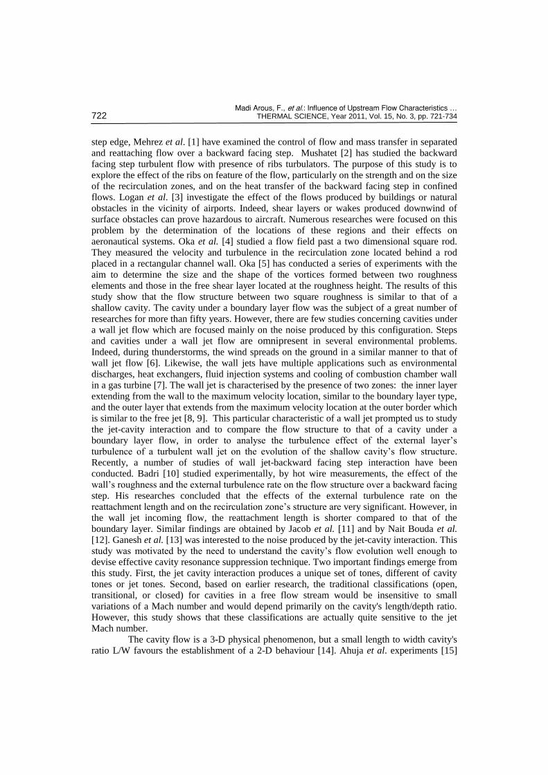
step edge, Mehrez et al. [1] have examined the control of flow and mass transfer in separated
and reattaching flow over a backward facing step. Mushatet [2] has studied the backward
facing step turbulent flow with presence of ribs turbulators. The purpose of this study is to
explore the effect of the ribs on feature of the flow, particularly on the strength and on the size
of the recirculation zones, and on the heat transfer of the backward facing step in confined
flows. Logan et al. [3] investigate the effect of the flows produced by buildings or natural
obstacles in the vicinity of airports. Indeed, shear layers or wakes produced downwind of
surface obstacles can prove hazardous to aircraft. Numerous researches were focused on this
problem by the determination of the locations of these regions and their effects on
aeronautical systems. Oka et al. [4] studied a flow field past a two dimensional square rod.
They measured the velocity and turbulence in the recirculation zone located behind a rod
placed in a rectangular channel wall. Oka [5] has conducted a series of experiments with the
aim to determine the size and the shape of the vortices formed between two roughness
elements and those in the free shear layer located at the roughness height. The results of this
study show that the flow structure between two square roughness is similar to that of a
shallow cavity. The cavity under a boundary layer flow was the subject of a great number of
researches for more than fifty years. However, there are few studies concerning cavities under
a wall jet flow which are focused mainly on the noise produced by this configuration. Steps
and cavities under a wall jet flow are omnipresent in several environmental problems.
Indeed, during thunderstorms, the wind spreads on the ground in a similar manner to that of
wall jet flow [6]. Likewise, the wall jets have multiple applications such as environmental
discharges, heat exchangers, fluid injection systems and cooling of combustion chamber wall
in a gas turbine [7]. The wall jet is characterised by the presence of two zones: the inner layer
extending from the wall to the maximum velocity location, similar to the boundary layer type,
and the outer layer that extends from the maximum velocity location at the outer border which
is similar to the free jet [8, 9]. This particular characteristic of a wall jet prompted us to study
the jet-cavity interaction and to compare the flow structure to that of a cavity under a
boundary layer flow, in order to analyse the turbulence effect of the external layer’s
turbulence of a turbulent wall jet on the evolution of the shallow cavity’s flow structure.
Recently, a number of studies of wall jet-backward facing step interaction have been
conducted. Badri [10] studied experimentally, by hot wire measurements, the effect of the
wall’s roughness and the external turbulence rate on the flow structure over a backward facing
step. His researches concluded that the effects of the external turbulence rate on the
reattachment length and on the recirculation zone’s structure are very significant. However, in
the wall jet incoming flow, the reattachment length is shorter compared to that of the
boundary layer. Similar findings are obtained by Jacob et al. [11] and by Nait Bouda et al. [12]. Ganesh et al. [13] was interested to the noise produced by the jet-cavity interaction. This
study was motivated by the need to understand the cavity’s flow evolution well enough to
devise effective cavity resonance suppression technique. Two important findings emerge from
this study. First, the jet cavity interaction produces a unique set of tones, different of cavity
tones or jet tones. Second, based on earlier research, the traditional classifications (open,
transitional, or closed) for cavities in a free flow stream would be insensitive to small
variations of a Mach number and would depend primarily on the cavity's length/depth ratio.
However, this study shows that these classifications are actually quite sensitive to the jet
Mach number.
The cavity flow is a 3-D physical phenomenon, but a small length to width cavity's
ratio L/W favours the establishment of a 2-D behaviour [14]. Ahuja et al. experiments [15]

Madi Arous, F., et al.: Influence of Upstream Flow Characteristics … THERMAL SCIENCE, Year 2011, Vol. 15, No. 3, pp. 721-734 723
showed that the cavity flow is essentially 2-D for L/W < 1. Numerous studies have shown that
the 2-D simulation constitutes a good approximation [16-18]. In view of that, we considered
in the present study a 2-D turbulent cavity flow. The purpose of this study is examining the
influence of the inflow characteristics on the flow behaviour of shallow cavities, particularly
on the reattachment phenomenon. Accordingly, the comparison of cavities’ flow structures
was carried out for two different upstream flows: a boundary layer flow and a wall jet flow.
The comparison was performed for three different cavities of large aspect ratio: AR = 14, AR =
= 12, and AR = 10.
Formulation of the problem
The geometrical parameters of the problems considered in this study, the Reynolds
number and the boundary layer thickness at leading edge (x = 0) are identical to those of the
experiments of Badri [10] and those of Nait Bouda et al. [12]. The cavities’ depth H is equal
to 2 cm, the nozzles’ height b is equal to 4 cm, the distance between the jet exit and the cavity
D is equal to 110 cm, the Reynolds number and the boundary layer thickness at the leading
edge are equal to 7600 and 2 cm, respectively, for both incoming flows considered in this
study.
The governing equations
The flow fields for 2-D, incompressible, isotherm and statistically steady flow are
governed by the following conservative equations in Cartesian tensor notations:
– mass = 0j
j
U
x (1)
– momentum 1i i
j i j
j i j j
U UPU u u
x x x x (2)
where is the kinematic viscosity and Uj – the velocity component in the j-direction.
Turbulence modelling
The closure of the governing equations is realised by the low-Re stress omega
model. It is a stress-transport model based on the omega equation and Launder, Reece, and
Rodi (LRR) model. The low-Re stress omega is a multi-scale model which has a wide range
of applications. This model has proven to be accurate for wall-bounded flows, including
separation [19]. The low-Re stress-omega solves the Reynolds’ stresses transport equations in
addition to an equation for the specific dissipation rate w. This means that five additional
transport equations are required in 2-D flows. Kolmogorov defined ω as the rate of energy
dissipation per unit volume and time; the inverse of ω is the time scale along which
dissipation of turbulence energy occurs [19].
The exact equation of the Reynolds stress τij, for an incompressible and statistically
steady flow, is in the following form [19]:
Madi Arous, F., et al.: Influence of Upstream Flow Characteristics … 724 THERMAL SCIENCE, Year 2011, Vol. 15, No. 3, pp. 721-734
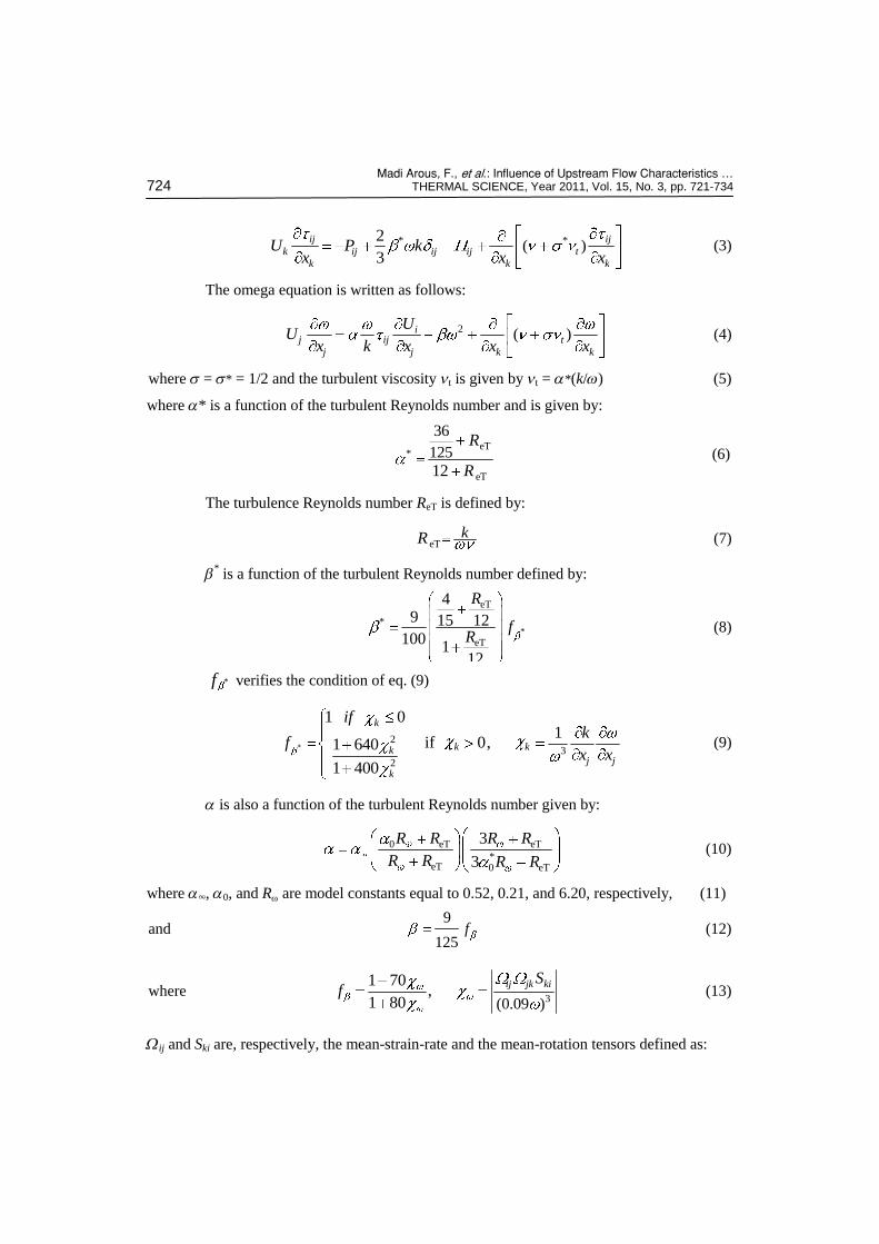
* *( )2
3
ij ij
k ij ij ij t
k k k
U P kx x x
(3)
The omega equation is written as follows:
2 ( )ij ij t
j j k k
UU
x k x x x (4)
where s = s* = 1/2 and the turbulent viscosity nt is given by nt = a*(k/w) (5)
where a* is a function of the turbulent Reynolds number and is given by:
eT
*
eT
36
125
12
R
R (6)
The turbulence Reynolds number ReT is defined by:
eTkR (7)
b
* is a function of the turbulent Reynolds number defined by:
*
eT
*
eT
49 15 12
1001
12
R
fR
(8)
*f verifies the condition of eq. (9)
*2
3
2
1 01
if 0,1 640
1 400
k
k kkj j
k
ifk
fx x
(9)
a is also a function of the turbulent Reynolds number given by:
0 eT eT
*eT 0 eT
3
3
R R R R
R R R R (10)
where a, a0, and Rw are model constants equal to 0.52, 0.21, and 6.20, respectively, (11)
and 9
125f (12)
where 3(0.09 )
1 70,
1 80
ij jk kiSf (13)
Wij and Ski are, respectively, the mean-strain-rate and the mean-rotation tensors defined as:
Madi Arous, F., et al.: Influence of Upstream Flow Characteristics … THERMAL SCIENCE, Year 2011, Vol. 15, No. 3, pp. 721-734 725
,1 1
2 2
j ji iij ij
j i j i
U UU US
x x x x (14)
The stress omega model does not require a wall-reflexion term in pressure-strain
term Πij which can be written for the low-Re stress omega model as:
*
1
2 2 2 1ˆˆ ˆ3 3 3 3
ij ij ij ij ij ij ij ij kk ijC k P P D P k S S (15)
where , ,1
2
j i m mij im jm ij im jm kk
m m j i
U U U UP D P P
x x x x (16)
The closure coefficients, when low Re number correction is included, are given by:
where 2 2 28 8 2 60 4ˆˆ ˆ, ,11 11 55
C C C (18)
The constants C1, C2, and 0
ˆ 1.8, 0.52, and 0.007, respectively. (19)
Numerical procedure
The equations of the mean and the turbulent fields are discretized using the finite
volume method [20] on non-uniform meshes. SIMPLEC algorithm (SIMPLE-Consistent) and
power law interpolation scheme (PLDS) are used for pressure-velocity coupling and for the
convection-diffusion interpolation term, respectively.
The convergence of the scheme is based on scaled residuals for the continuity,
momentum, omega and Reynolds stress components. The scaled residuals for convergence are
set between 10–6
and 10–8
. The solution obtained when all the scaled residuals are less than or
equal to this prescribed values and the physical quantities are monotonous. The grids used for
all cases presented in this study (wall jet, backward facing step, and cavities) are refined near
the walls in order to take into account the viscous sublayer effect.
Boundary conditions
Figure 1 shows the computational domain and the boundary conditions. At inflow
boundary [AF], constant velocity profile, turbulent intensity, and turbulent length scale are imposed:
1/2
2in in 1/4
3, 0, ( ) , and
2
kU U V k IU
C
where I is the turbulence intensity rate, ℓ – a turbulent length scale, and Cm – an empirical
constant equal to 0.09 specified in the turbulence model.
eT eT 0 eT
eT eT eT
ˆ ˆ12 12ˆ ˆˆ ˆ ˆ, ,12 12 12
R R R
R R R (17)

Madi Arous, F., et al.: Influence of Upstream Flow Characteristics … 726 THERMAL SCIENCE, Year 2011, Vol. 15, No. 3, pp. 721-734
Figure 1. Schematic diagram and computational domain
These values allow having the experimental inlet conditions at the leading edge (x = 0).
At the outflow boundaries (DE) and (EG), zero pressure is imposed. At the walls, the no-slip
boundary conditions (U = V = 0) are imposed. Fluent computes the near-wall values of the
Reynolds stresses and the specific dissipation rate w from wall functions.
Results and discussion
Validation
Similarity analysis of wall jet flow
Initially, a simulation of a wall jet was
undertaken in order to verify the similarity of
the upstream flow with that of the experi-
mental wall jet. The normalized velocities
U/Umax. vs. y/y1/2 have been compared with
previous experimental results of Eriksson et al. [9] as shown in fig. 2. The good agre-
ement between the numerical prediction with
the experimental ones allows us to confirm
that the incoming flow is a wall jet flow.
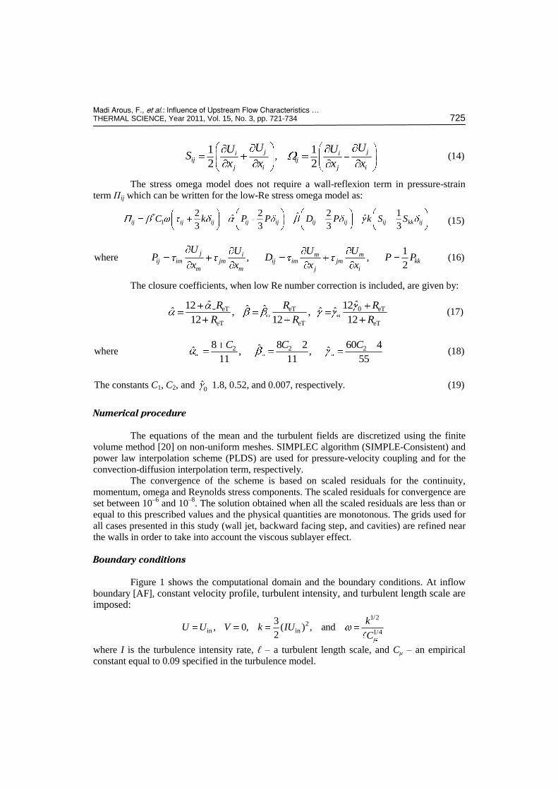
Figure 3 shows a log-log plot of Umax./U0
vs. y1/2/b. We observe an excellent agre-
ement with the similarity requirement of a
power law relation between Umax and y1/2,
i. e. Umax./U0 = B0(y1/2/b)n; the values of B0 =
= 1.084 and n = –0.53 are in perfect accor-
dance with the Karlsson et al. experimental ones [21], in which B0 = 1.09 and n = –0.528.
Figure 4 displays the dimensionless growth rate of the wall jet, in terms of jet half-
width. The half-width y1/2, varies linearly with x distance. This numerical result is in a good
Figure 2. Wall jet mean velocity profile in outer scaling
Madi Arous, F., et al.: Influence of Upstream Flow Characteristics … THERMAL SCIENCE, Year 2011, Vol. 15, No. 3, pp. 721-734 727
agreement with the Karlsson et al. results [21], Abrahamsson et al. results [22], and those of
Wygnanski et al. experimental ones [23].
Figure 3. Decay of stream wise mean velocity
Figure 4. Variation of half-width with
downstream distance
Backward facing step under a wall jet flow
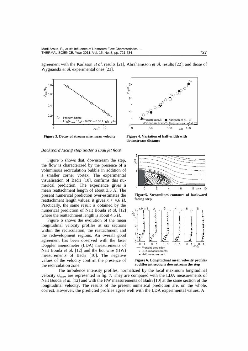
Figure 5 shows that, downstream the step,
the flow is characterized by the presence of a
voluminous recirculation bubble in addition of
a smaller corner vortex. The experimental
visualisation of Badri [10], confirms this nu-
merical prediction. The experience gives a
mean reattachment length of about 3.5 H. The
present numerical prediction over-estimates the
reattachment length values; it gives xr ≈ 4.6 H.
Practically, the same result is obtained by the
numerical prediction of Nait Bouda et al. [12]
where the reattachment length is about 4.5 H.
Figure 6 shows the evolution of the mean
longitudinal velocity profiles at six sections
within the recirculation, the reattachment and
the redevelopment regions. An overall good
agreement has been observed with the laser
Doppler anemometer (LDA) measurements of
Nait Bouda et al. [12] and the hot wire (HW)
measurements of Badri [10]. The negative
values of the velocity confirm the presence of
the recirculation zone.
The turbulence intensity profiles, normalized by the local maximum longitudinal
velocity Umax, are represented in fig. 7. They are compared with the LDA measurements of
Nait Bouda et al. [12] and with the HW measurements of Badri [10] at the same section of the
longitudinal velocity. The results of the present numerical prediction are, on the whole,
correct. However, the predicted profiles agree well with the LDA experimental values. A
Figure5. Streamlines contours of backward facing step
Figure 6. Longitudinal mean velocity profiles at different sections downstream the step

Madi Arous, F., et al.: Influence of Upstream Flow Characteristics … 728 THERMAL SCIENCE, Year 2011, Vol. 15, No. 3, pp. 721-734
good agreement between the aspect of the
numerical profiles and that of the experi-
ments has been observed.
Cavity-flow
The Reynolds number and the boundary
layer thickness at the leading edge (x = 0), for
the two incoming flows considered in this
study are identical and equal to 7600 and 2 cm,
respectively.
Analysis of the wall static pressure
Figure 8 displays the static pressure distribution at the bottom of the cavities for two
different upstream flows: a boundary layer and a wall jet inflow; the pressure coefficients
values approach those of Roshko [24]. For the cases considered in this paper, we observe that
just behind the upstream step (x/H ≤ 3) the pressure is uniform then it increases with the
increasing x/H.
For AR = 10, under a
boundary layer flow, the
pressure distribution has a
concave-up shape but under
a wall jet flow the pressure
distribution changes from
concave-up shape to a
concave-down shape. How-
ever, according to the clas-
sification of Plentovich et al. [25], in the first case the
flow is an “open cavity
flow” but in the second case
it is an “open transitional
cavity flow”.
For AR = 12, the
pressure distribution shows
that under a boundary layer,
the flow is an “open/ transi-
tional” flow but under a
wall jet flow it is a “closed
cavity flow”, in this latter,
an inflection occurs in the
pressure distribution.
For AR = 14, under a boundary layer, the flow is a “transitional closed cavity flow”
and under a wall jet flow, it is a “closed cavity flow” [25].
Figure 7. Turbulence intensity /1/ 22
max.( )u U evolution downstream the step
Figure 8. Static pressure coefficients evolution

Madi Arous, F., et al.: Influence of Upstream Flow Characteristics … THERMAL SCIENCE, Year 2011, Vol. 15, No. 3, pp. 721-734 729
Analysis of the mean flow field
Figure 9 illustrates the flow structures of all cases considered in this study. It is
interesting to notice the presence of three recirculation bubbles inside the cavity; the principal
one is located behind the forward step and two others close to the corners of the cavity. A
similar shallow cavity flow structure has been highlighted by the experiments of Avelar et al. [26] and by the numerical results of Zdanski et al. [27]. In the boundary layer incoming flow,
we note that the decrease of the cavity aspect ratio leads a decrease of the distance between
the main vortex and the one located in front of the downstream step. These two vortices are
touching each other in the cavity of an aspect ratio of 10. These results are in perfect
agreement with the experimental ones of Oka [5] where an analogous flow structure, between two square roughness, was evidenced. It was found that these two vortices are
separated by the reattachment boundary layer when the two roughness elements are separated
by a distance of 14 H while there are touching when this distance is of 9 H. In the wall jet
incoming flow, the fig. 9 reveals the presence of another recirculation zone over the aft step,
which size increase with the increasing of the cavity’s aspect ratio.
Figure 9. Streamlines contours for the three cavities aspect ratios (AR = 14, AR = 12,
and AR = 10)
Madi Arous, F., et al.: Influence of Upstream Flow Characteristics … 730 THERMAL SCIENCE, Year 2011, Vol. 15, No. 3, pp. 721-734
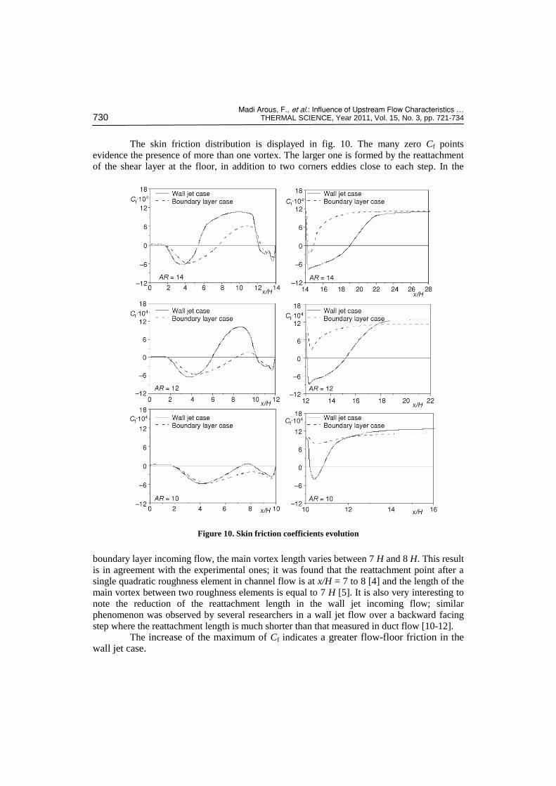
The skin friction distribution is displayed in fig. 10. The many zero Cf points
evidence the presence of more than one vortex. The larger one is formed by the reattachment
of the shear layer at the floor, in addition to two corners eddies close to each step. In the
boundary layer incoming flow, the main vortex length varies between 7 H and 8 H. This result
is in agreement with the experimental ones; it was found that the reattachment point after a
single quadratic roughness element in channel flow is at x/H = 7 to 8 [4] and the length of the
main vortex between two roughness elements is equal to 7 H [5]. It is also very interesting to
note the reduction of the reattachment length in the wall jet incoming flow; similar
phenomenon was observed by several researchers in a wall jet flow over a backward facing
step where the reattachment length is much shorter than that measured in duct flow [10-12].
The increase of the maximum of Cf indicates a greater flow-floor friction in the wall jet case.
Figure 10. Skin friction coefficients evolution
Madi Arous, F., et al.: Influence of Upstream Flow Characteristics … THERMAL SCIENCE, Year 2011, Vol. 15, No. 3, pp. 721-734 731
Analysis of the turbulent flow field
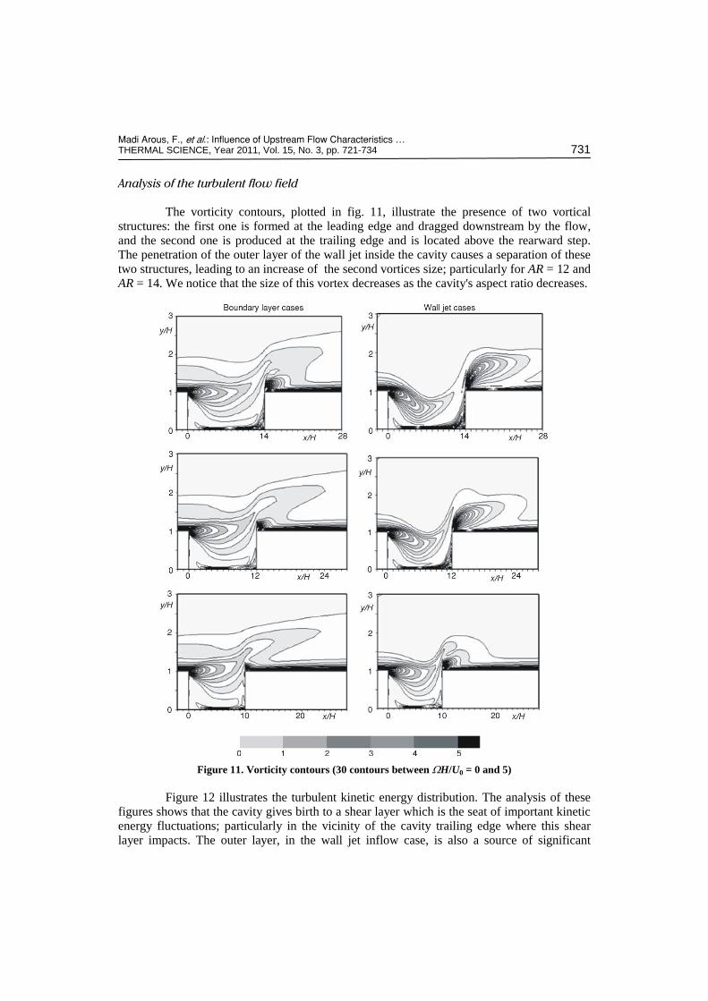
The vorticity contours, plotted in fig. 11, illustrate the presence of two vortical
structures: the first one is formed at the leading edge and dragged downstream by the flow,
and the second one is produced at the trailing edge and is located above the rearward step.
The penetration of the outer layer of the wall jet inside the cavity causes a separation of these
two structures, leading to an increase of the second vortices size; particularly for AR = 12 and
AR = 14. We notice that the size of this vortex decreases as the cavity's aspect ratio decreases.
Figure 12 illustrates the turbulent kinetic energy distribution. The analysis of these
figures shows that the cavity gives birth to a shear layer which is the seat of important kinetic
energy fluctuations; particularly in the vicinity of the cavity trailing edge where this shear
layer impacts. The outer layer, in the wall jet inflow case, is also a source of significant
Figure 11. Vorticity contours (30 contours between WH/U0 = 0 and 5)

Madi Arous, F., et al.: Influence of Upstream Flow Characteristics … 732 THERMAL SCIENCE, Year 2011, Vol. 15, No. 3, pp. 721-734
kinetic energy fluctuations. The increases of the cavity's aspect ratio causes a penetration of
this external shear layer inside the cavity, thus compressing the internal shear layer.
Figure 12. Turbulent kinetic energy contours
Conclusions
The cavity flow is largely used in several practical devices. The major part of
previous researches concerns the cavities under a boundary layer flow. The effect of several
parameters, on the behaviour of the cavity flow, was the subject of numerous researches since
the fifties. Among these parameters: the Mach number, the Reynolds number, the cavity’s
aspect ratio, and the leading edge boundary layer thickness. The present study deals with the
effect of the inflow characteristics on the shallow flow structure and on the reattachment
phenomenon. The choice of a cavity under a wall jet flow is dictated by the presence of this
Madi Arous, F., et al.: Influence of Upstream Flow Characteristics … THERMAL SCIENCE, Year 2011, Vol. 15, No. 3, pp. 721-734 733
configuration in several practical fields in addition to the interest of the wall jets in the
industry.
The numerical approach is based on the low-Re stress omega model which is based
on the omega equation and LRR model. A numerical prediction of a wall jet flow and a wall
jet flow over a backward facing step allowed comparisons with experimental data and the
validation of the turbulence model. The results of these preliminary studies are also in good
agreement with the previous numerical results based on the RSMKFL2 model.
The numerical prediction of the flow pattern of a shallow cavity reveals the presence
of three recirculation zones inside the cavity. The main one is located behind the upstream
step and two secondary ones close to the corners of the cavity. In the boundary layer incoming
flow, the length of the principal vortex is about 7 H to 8 H in accordance to some previous
studies.
However, the reattachment process seems to be accelerated in the wall jet inflow
case where the reattachment length is considerably reduced compared to that of the boundary
layer inflow case. This reduction can be attributed to an additional turbulent diffusive transfer
due to the energetic eddying motions in the external flow layer of the wall jet. This same
phenomenon has been observed in the wall jet-backward facing step interaction. Moreover,
the penetration of this external layer inside the cavity generates an important bubble above the
rearward step, which size’s increases with the increasing of the cavity’s aspect ratio.
Acknowledgments
The authors wish to thank the polytechnic military School of Algiers (EMP) for their
collaboration to use the CFD fluent code.
Nomenclature
AR – cavity aspect ratio (= L/H), [–] b – nozzle height, [m] Cf – skin friction coefficient, (= 2tw/r 2
oU ) Cp – pressure coefficient, – (= 2(P – Pref)/
2oU )
H – cavity depth, [m] k – turbulence kinetic energy, [m–2s–2] L – cavity length, [m] P – static pressure, [Nm–2] Re – Reynolds number (= U0H/n), [–] U – streamwise velocity component, [ms–1] U0 – maximum streamwise velocity at – x = 0, [ms–1] V – vertical velocity component, [ms–1] W – cavity width, [m]
x – stream-wise co-ordinate, [m] xR – reattachment length, [m] y – vertical co-ordinate, [m] y1/2 – vertical co-ordinate where U = U0/2, [m]
Greek symbols
ij – Kronecker delta, [–] – kinematic viscosity, [m2s–1]
t – turbulent viscosity, [m2s–1] – fluid density, [kgm–3] tij – Reynolds stress, [m2s–2] tw – wall shear stress, [Nm–2] w – specific dissipation rate, [s–1] Ωi – mean rate of rotation, [s–1]
References
[1] Mehrez, Z., et al., Mass Transfer Control of a Backward Facing Step Flow by Local Forcing Effect of Reynolds Number, Thermal Science, 15 (2011), 2, pp. 367-378
[2] Mushatet Khudheyer, S., Simulation of Turbulent Flow and Heat Transfer over a Backward Facing Step with Ribs Turbulators, Thermal Science, 15 (2011), 1, pp. 245-255
[3] Logan, E., Prapoj, P., Chang, J., A Comparison of Wake Characteristics of Model and Prototype Buildings in Transverse Winds, NASA contractor report No. 3008, 1978
Madi Arous, F., et al.: Influence of Upstream Flow Characteristics … 734 THERMAL SCIENCE, Year 2011, Vol. 15, No. 3, pp. 721-734
[4] Oka, S., Kostic, Z., Flow Field Past a Single Roughness Element in Channel of Rectangular Cross--Section, in: Heat and Mass Transfer in a Boundary Layer (Eds. N. H. Afgan, Z. Zaric, P. Anastasijevic), Pergamon Press, New York, USA, Vol. 1, pp. 425-435, 1972
[5] Oka, S., Flow Field between Two Roughness Elements in Developed Turbulent Chanel Flow, in: Heat and Mass Transfer in Flows with Separated Regions and Measurement Techniques, Pergamon Press, New York, USA, 1972
[6] Mudgal, B. V., Pani, B. S., Flow Around Obstacles in Plane Turbulent Wall Jets, Journal of Wind Engineering and Industrial Aerodynamics, 73 (1998), 3, pp. 193-213
[7] Kanna, R. P., Das, M. K., Numerical Simulation of Two-Dimensional Laminar Incompressible offset Jet Flows, International Journal for Numerical Methods in Fluids, 49 (2005), 4, pp. 439-464
[8] Bajura, R. A., Szewczyk, A. A., Experimental Investigation of a Laminar Two-Dimensional Plane Wall Jet, Phys. Fluids, 13 (1970), 7, pp. 1653-1664
[9] Eriksson, J., Karlsson, R. I., Persson, J., An Experimental Study of a Two-Dimensional Plane Turbulent Wall Jet, J. Experiments in Fluids, 25 (1998), 1, pp. 50-60
[10] Badri, K., Experimental Study of aTurbulent Flow Downstream a Backward Facing Step: a Wall Jet Flow Case and a Boundary Layer Case, Ph. D. thesis (in French), Graduate School for Engineering Sciences, Nantes, France, 1993
[11] Jacob, M. C., et al., Experimental Study of Sound Generated by Backward Facing Steps under Wall Jet, AIAA Journal, 392 (2001), 7, pp. 1254-1260
[12] Nait Bouda, N., et al., Experimental Approach and Numerical Prediction of Turbulent Wall Jet over a Backward Facing Step, International Journal of Heat and Fluids Flow, 29 (2008), 4, pp. 927-944
[13] Ganesh, R., Edmane, E., Timoty, J. B, Tone Noise and Nearfield Pressure Produced by Jet-Cavity Interaction, Nasa Technical Report No. TM-20883, 1998
[14] Gloerfelt, X., Bailly, C., Juvé, D., Direct Computational of the Noise Radiation by a Subsonic Cavity Flow and Application of Integral Methods, Journal of Sound and Vibration, 266 (2003), pp. 119-146
[15] Ahuja, K. K., Mendoza, J., Effects of Cavity Dimensions, Boundary Layer and Temperature on Cavity Noise with Emphasis on Benchmark Data to Validate Computational Aeroacoustic Codes, NASA Contractor Report No. 4653, 1995
[16] Colonius, T., Basu, A. J., Rowley, C. W., Numerical Investigation of Flow Past a Cavity, AIAA paper, 99 (1912), 5th AIAA/CEAS Aeroacoustics Conference, Greater Seattle, Wa., USA, 1999
[17] Zdanski, P. S. B, et al., On the Flow over Cavities of Large Aspect Ratio: A Physical Analysis, International Communications in Heat and Mass Transfer, 33 (2006), 4, pp. 458-466
[18] Alammar, K. N., Effect of Cavity Aspect Ratio on Flow and Heat Transfer Characteristics in Pipes: A Numerical Study, Heat and Mass Transfer, 42 (2006), 9, pp. 861-866
[19] Wilcox, D. C., Turbulence Modelling for CFD, 2nd DCW Industries, Inc., La Canada, Cal., USA, 1998 [20] Patankar, S. V., Numerical Heat Transfer and Fluid Flow, Series in Computational Methods in
Mechanics and Thermal Sciences, Hemisphere Publishing Corporation, New York, USA, 1980 [21] Abrahamsson, H., Johansson, B., Löfdahl, L., A Turbulent Plane Two-Dimensional Wall-Jet in a
Quiescent Surrounding, European Journal of Mechanics. B, Fluids, 13 (1994), 5, pp. 533-556 [22] Karlsson, R., Eriksson, J., Persson, J., An Experimental Study of a Two-Dimensional Plane Turbulent
Wall Jet, Technical report No.VU-S93-B3, Vattenfall Utveckling AB, Älvkarleby Laboratory, Sweden, 1993
[23] Wygnanski, I., Katz, Y., Horev, E., On the Applicability of Various Scaling Laws to the Turbulent Wall jet, Journal of. Fluid Mechanics, 234 (1992), April, pp. 669-690
[24] Roshko, A., Some Measurements of Flow in a Rectangular Cutout, NACA Technical Note No. 3448, 1955
[25] Plentovich, E. B, Stallings, Jr. R. L., Tracy, M. B., Experimental Cavity Pressure Measurements at Subsonic Speeds, Nasa Technical Paper No. 3358, 1993
[26] Avelar, A. C., Fico, N. G. C. R., Mello, O. A. F., Three-Dimensional Flow over Shallow Cavities, 37th AIAA Fluid Dynamics Conference and Exhibit, Miami, Fla., USA, 4234, 2007
[27] Zdanski, P. S. B, et al., Numerical Study of the Flow over Shallow Cavities, Computers & Fluids, 32 (2003), 7, pp. 953-974
Paper submitted: December 30, 2010 Paper revised: January 27, 2011 Paper accepted: February, 15, 2011