Influence of Tool Geometry and Process Parameters on ...
21
materials Article Influence of Tool Geometry and Process Parameters on Torque, Temperature, and Quality of Friction Stir Welds in Dissimilar Al Alloys Neves Manuel 1,2 , Daniel Beltrão 1 , Ivan Galvão 1,3, * , Rui M. Leal 1,4 , José D. Costa 1 and Altino Loureiro 1 Citation: Manuel, N.; Beltrão, D.; Galvão, I.; Leal, R.M.; Costa, J.D.; Loureiro, A. Influence of Tool Geometry and Process Parameters on Torque, Temperature, and Quality of Friction Stir Welds in Dissimilar Al Alloys. Materials 2021, 14, 6020. https://doi.org/10.3390/ma14206020 Academic Editor: Bolv Xiao Received: 16 September 2021 Accepted: 9 October 2021 Published: 13 October 2021 Publisher’s Note: MDPI stays neutral with regard to jurisdictional claims in published maps and institutional affil- iations. Copyright: © 2021 by the authors. Licensee MDPI, Basel, Switzerland. This article is an open access article distributed under the terms and conditions of the Creative Commons Attribution (CC BY) license (https:// creativecommons.org/licenses/by/ 4.0/). 1 Univ Coimbra, CEMMPRE, Departamento de Engenharia Mecânica, Rua Luís Reis Santos, 3030-788 Coimbra, Portugal; [email protected] (N.M.); [email protected] (D.B.); [email protected] (R.M.L.); [email protected] (J.D.C.); [email protected] (A.L.) 2 Faculdade de Engenharia e Tecnologia, Universidade do Namibe, Campus Farol Noronha, Moçâmedes 274, Angola 3 ISEL, Departamento de Engenharia Mecânica, Instituto Politécnico de Lisboa, Rua Conselheiro Emídio Navarro 1, 1959-007 Lisboa, Portugal 4 LIDA-ESAD.CR, Instituto Politécnico de Leiria, Rua Isidoro Inácio Alves de Carvalho, 2500-321 Caldas da Rainha, Portugal * Correspondence: [email protected] Abstract: In the current investigation, the influence of the tool geometry, the position of the materials in the joint, the welding speed on the temperature and torque developed, and on the quality of the welds in dissimilar and tri-dissimilar T joints were analysed. The aluminium alloys used were AA2017-T4, AA6082-T6, and AA5083-H111 and the friction stir welds were performed with identical shoulder tools, but with either a pin with simple geometry or a pin with progressive geometry. Progressive pin tools proved to be a viable alternative in the production of dissimilar and tri- dissimilar welds, as they provide a larger tool/material friction area and a larger volume of dragged material, which promotes an increase in the heat generated and a good mixing of the materials in the stir zone, although they require a higher torque. Placing a stronger material on the advancing side also results in a higher temperature in the stir zone but requires higher torque too. The combination of these factors showed that tools with a progressive pin provide sound dissimilar and tri-dissimilar welds, unlike single-pin tools. The increase in the welding speed causes the formation of defects in the stir zone, even in tri-dissimilar welds carried out with a tool with a progressive pin, which impairs the fatigue strength of the welds. Keywords: friction stir welding; tool geometry; dissimilar aluminium alloys; torque; temperature 1. Introduction There is a trend in shipbuilding of increasingly using aluminium alloys in boat build- ing to reduce weight, increase payload, and reduce the fuel consumption of ships. Alu- minium alloys of the 5xxx and 2xxx series are used in the submerged hulls of the ships, while the superstructures are typically produced in 6xxx alloys. To increase the stiffness of the naval structures, without significantly increasing the weight, the plates are usually reinforced with a stringer, giving rise to T-joints. However, the production of aluminium T-joints by conventional fusion-welding techniques may lead to weaknesses, often pro- moting significant distortion and the formation of metallurgical defects in the welded components [1]. However, friction stir welding (FSW) is a very suitable alternative to produce T-joints in aluminium alloys. As it is a solid-state technology, the heat-input during the process is much lower than in conventional techniques, which results in a significant reduction in the metallurgical problems occurring during welding and enables the production of components with good dimensional stability and lower distortion [2]. Materials 2021, 14, 6020. https://doi.org/10.3390/ma14206020 https://www.mdpi.com/journal/materials
Transcript of Influence of Tool Geometry and Process Parameters on ...

materials
Article
Influence of Tool Geometry and Process Parameters on Torque,Temperature, and Quality of Friction Stir Welds in DissimilarAl Alloys
Neves Manuel 1,2 , Daniel Beltrão 1, Ivan Galvão 1,3,* , Rui M. Leal 1,4 , José D. Costa 1 and Altino Loureiro 1
�����������������
Citation: Manuel, N.; Beltrão, D.;
Galvão, I.; Leal, R.M.; Costa, J.D.;
Loureiro, A. Influence of Tool
Geometry and Process Parameters on
Torque, Temperature, and Quality of
Friction Stir Welds in Dissimilar Al
Alloys. Materials 2021, 14, 6020.
https://doi.org/10.3390/ma14206020
Academic Editor: Bolv Xiao
Received: 16 September 2021
Accepted: 9 October 2021
Published: 13 October 2021
Publisher’s Note: MDPI stays neutral
with regard to jurisdictional claims in
published maps and institutional affil-
iations.
Copyright: © 2021 by the authors.
Licensee MDPI, Basel, Switzerland.
This article is an open access article
distributed under the terms and
conditions of the Creative Commons
Attribution (CC BY) license (https://
creativecommons.org/licenses/by/
4.0/).
1 Univ Coimbra, CEMMPRE, Departamento de Engenharia Mecânica, Rua Luís Reis Santos,3030-788 Coimbra, Portugal; [email protected] (N.M.); [email protected] (D.B.);[email protected] (R.M.L.); [email protected] (J.D.C.); [email protected] (A.L.)
2 Faculdade de Engenharia e Tecnologia, Universidade do Namibe, Campus Farol Noronha,Moçâmedes 274, Angola
3 ISEL, Departamento de Engenharia Mecânica, Instituto Politécnico de Lisboa,Rua Conselheiro Emídio Navarro 1, 1959-007 Lisboa, Portugal
4 LIDA-ESAD.CR, Instituto Politécnico de Leiria, Rua Isidoro Inácio Alves de Carvalho,2500-321 Caldas da Rainha, Portugal
* Correspondence: [email protected]
Abstract: In the current investigation, the influence of the tool geometry, the position of the materialsin the joint, the welding speed on the temperature and torque developed, and on the quality ofthe welds in dissimilar and tri-dissimilar T joints were analysed. The aluminium alloys used wereAA2017-T4, AA6082-T6, and AA5083-H111 and the friction stir welds were performed with identicalshoulder tools, but with either a pin with simple geometry or a pin with progressive geometry.Progressive pin tools proved to be a viable alternative in the production of dissimilar and tri-dissimilar welds, as they provide a larger tool/material friction area and a larger volume of draggedmaterial, which promotes an increase in the heat generated and a good mixing of the materials in thestir zone, although they require a higher torque. Placing a stronger material on the advancing sidealso results in a higher temperature in the stir zone but requires higher torque too. The combinationof these factors showed that tools with a progressive pin provide sound dissimilar and tri-dissimilarwelds, unlike single-pin tools. The increase in the welding speed causes the formation of defectsin the stir zone, even in tri-dissimilar welds carried out with a tool with a progressive pin, whichimpairs the fatigue strength of the welds.
Keywords: friction stir welding; tool geometry; dissimilar aluminium alloys; torque; temperature
1. Introduction
There is a trend in shipbuilding of increasingly using aluminium alloys in boat build-ing to reduce weight, increase payload, and reduce the fuel consumption of ships. Alu-minium alloys of the 5xxx and 2xxx series are used in the submerged hulls of the ships,while the superstructures are typically produced in 6xxx alloys. To increase the stiffnessof the naval structures, without significantly increasing the weight, the plates are usuallyreinforced with a stringer, giving rise to T-joints. However, the production of aluminiumT-joints by conventional fusion-welding techniques may lead to weaknesses, often pro-moting significant distortion and the formation of metallurgical defects in the weldedcomponents [1]. However, friction stir welding (FSW) is a very suitable alternative toproduce T-joints in aluminium alloys. As it is a solid-state technology, the heat-inputduring the process is much lower than in conventional techniques, which results in asignificant reduction in the metallurgical problems occurring during welding and enablesthe production of components with good dimensional stability and lower distortion [2].
Materials 2021, 14, 6020. https://doi.org/10.3390/ma14206020 https://www.mdpi.com/journal/materials
Materials 2021, 14, 6020 2 of 21
The characteristics of the FS welds are determined by the thermomechanical conditionsexperienced by the materials during welding. These conditions, which are closely relatedto the generation of strain and heat, significantly influence the material flow and the weldmicrostructure [3]. As a result, it is mandatory to understand the influence of the weldingparameters, such as: the tool rotation and welding speeds, the tool geometry, and thebase material properties on the thermomechanical conditions. The optimisation of thewelding parameters has been extensively studied with the analysis of microstructural andmechanical properties in similar and dissimilar FSW [4,5]. Welding torque and temperaturehave also been used as parameters to control the welding results due to their strong relationto the heat generated during the process [6,7]. Yan et al. [8] reported that the torqueincreases in increments with the welding speed and low torque values are associated withhigh heat-input conditions. In good agreement with this, Arora et al. [9] explained that thedecrease in torque for lower welding speeds is associated with the decrease in the volumeof material being deformed by the tool with each revolution. As the heat is generated in asmaller volume, this leads to a higher temperature in the material and a lower flow stress.According to Leitão et al. [10], the main factors governing the torque values are the rotationspeed and the plate’s thickness because of their influence on the generation of heat andthe distribution of heat throughout the thickness and flow of materials. These authors alsoreported that the plastic properties of the base materials also have a strong impact on thetorque values.
The influence of the tool geometry on the welding torque has also been addressed inthe literature. For example, Mehta et al. [11] investigated the torque and temperature infriction stir welding to optimise the diameter of the tool shoulder. In turn, Papahn et al. [12]compared the evolution of torque for three different tool geometries (triangular, non-threaded cylindrical, and threaded tapered pin). The authors observed that a lower torquewas registered when a threaded tapered pin was used to produce the welds. Additionally,they observed that the diameter of the tool shoulder was directly correlated with thetemperature reached, axial force, and the weld’s characteristics.
Recently, Andrade et al. [13], based on numerical simulation and published exper-imental results, concluded that the tool’s dimensions and its rotational speed directlyinfluence the torque and temperature reached during the welding. Torque decreases withincreasing tool rotation speed, while temperature increases with the tool rotation speedand the tool friction area. They also concluded that the welding speed and thickness of thebase material are secondary parameters of torque and temperature. Most of the studiesmentioned above refer to butt welds in the same material, therefore similar welds.
Regarding dissimilar welds, most studies focus on the influence of the welding param-eters and the relative position of materials (advancing or retreating side) on the morphologyand mechanical strength of welds and only a few on torque but, in any case, results arescarce and not always in agreement. Barbini et al. [14] stated, concerning the butt weldingof AA7050-T7651 and AA2024-T3 alloys, that welds with a better quality and a greater me-chanical resistance are obtained when the less resistant alloy (AA2024-T3) is placed on theadvancing side. Additionally, note that when the AA7050-T7651 alloy is placed on the ad-vancing side, there is a general reduction in torque. On the other hand, Cavalieire et al. [15]reported that higher torques and forces are registered when the strongest alloy, AA2024, isplaced on the advancing side when welded to AA6082. However, Elnabi et al. [16] reported,using statistical analysis, that in dissimilar welding of AA5454 to AA7075, the location ofthe base metal has negligible importance regarding the strength of the welds.
Concerning the production of T-joints by FSW, few studies have been conducted.Jesus et al. [17] showed the influence of the tool geometry on the morphology and me-chanical behaviour of similar welds in T-joint configuration in the AA6082 and AA5083alloys. Astarita et al. [18], analysing the feasibility of dissimilar T joints of AA 6056-T4and AA 2198-T3 by FSW, discovered flow defects, such as the lack of metallurgical con-tinuity between skin and stringer, which were found to play a significant role in bothmechanical and electrochemical behaviour. Tavares et al. [19] investigated the feasibility

Materials 2021, 14, 6020 3 of 21
and mechanical behaviour of welds with this geometry, between the AA7075-T6 (stringer)and AA6056-T4 (skin) alloys. They found that the welds had good mechanical strengthand a slight reduction in fatigue behaviour. More recently, Manuel et al. [20] studied thenugget formation and the mechanical behaviour of tri-dissimilar welds in AA2017-T4,AA5083-H111, and AA6082-T6 aluminium alloys. They showed that a high rotation totraverse speed ratio improves the overall weld quality, while increments in welding speedinfluence the weld morphology and fatigue strength. However, no studies were found onthe effect of the process parameters on the torque or temperature induced for this jointgeometry, whether for similar or dissimilar welds.
Despite the research already performed concerning the FSW of dissimilar T-joints,studies focused on analysing the influence of the tool geometry on welding temperatureand torque, and therefore on the quality and mechanical behaviour of the welds, arestill very scarce for this type of joint. Considering the very close relationship betweenthe process outputs and the thermomechanical conditions experienced during welding,the systematic production of dissimilar T-joints by FSW requires a profound study ofthe welding temperature and torque. Therefore, the aim of the current study was tocorrelate the torque and temperature registered during welding with the position of thebase material, the process parameters, and tool geometry and their consequences withregard to the quality of the weld.
2. Materials and Methods
T-joints in three different aluminium alloys, i.e., the heat-treatable AA2017-T4 andAA6082-T6 and the non-heat-treatable AA5083-H111, were produced by FSW, using ESABLegio FSW 3UL equipment. The chemical composition and the mechanical propertiesof these alloys, which were obtained experimentally, are presented in Tables 1 and 2,respectively. The joints were produced in the T-joint configuration, with the geometriccharacteristics illustrated in Figure 1. It may be observed that the joint is made of a skin,composed of two plates of 330 × 80 × 3 mm, and a stringer of 330 × 37.4 × 3 mm. Thestringer was made to protrude 1.4 mm above the skin to provide enough material to fill theempty volumes between plates and dies in the fillets, avoiding any reduction in the skin’sthickness.
Table 1. Chemical composition of the base materials (wt.%).
Alloys Cu Mg Mn Fe Si Zn Ti
AA2017-T4 4.5 0.8 1.0 0.7 0.8 0.25 0.15
AA5083-H111 0.025 4.5 0.57 0.18 0.09 0.01 0.01
AA6082-T6 0.09 0.6 1.0 0.44 0.81 0.08 0.03
Table 2. Mechanical properties of the base materials.
Properties AA2017-T4 AA5083-H111 AA6082-T6
Ultimate tensile strength (MPa) 427.0 317.5 321.0
Tensile yield strength (MPa) 276.0 158.0 288.0
Elongation at failure (%) 22.0 10.4 8.6
Vickers hardness (HV 0.2) 118.0 83.5 116.0

Materials 2021, 14, 6020 4 of 21Materials 2021, 14, x FOR PEER REVIEW 4 of 21
Figure 1. Welding setup and thermocouple location for the FSW joint.
Dissimilar and tri‐dissimilar welds were produced. For the dissimilar welds, two
welding configurations were tested. The AA5083 alloy was positioned as the skin and the
AA6082 alloy was positioned as the stringer in some joints, while the reverse welding
configuration was adopted for the other joints. On the other hand, the AA6082 alloy was
always positioned as the stringer plate in the tri‐dissimilar welds, due to its good ability
to deform plastically without creating cavities [21]. Even so, two welding configurations
were also tested for these joints, which were associated with the relative position of the
skin plates. Some welds were produced with the AA2017 alloy located on the advancing
side and with the AA5083 alloy located on the retreating side and other welds were
produced with the reverse positioning of the skin alloys.
As illustrated in Figure 2, four different tool designs were used to produce the welds.
The tools, which were manufactured in quenched and tempered H13 steel, of 50HRC
hardness, were composed of an 18 mm‐diameter concave shoulder, the same for all tools,
and a pin. Regarding the pin design, the tools were divided into two classes: with simple
pin design and with progressive pin design. The simple pin tool had a threaded conical
pin, designated (TP), and the other a flat pyramidal pin, designated (PP), both were 5.8
mm in length (Figure 2a,b). In turn, the progressive pin tools were composed of two
different parts, i.e., a threaded cylindrical upper part that was 2.5 mm long plus a threaded
conical tip (PTP) or a pyramidal tip (PPP), and both were 2.7 mm in length (Figure 2c,d).
Figure 2. Tool designs tested: (a) TP—threaded pin; (b) PP—pyramidal pin; (c) PTP—progressive
threaded pin; (d) PPP—progressive pyramidal pin.
Figure 1. Welding setup and thermocouple location for the FSW joint.
Dissimilar and tri-dissimilar welds were produced. For the dissimilar welds, twowelding configurations were tested. The AA5083 alloy was positioned as the skin andthe AA6082 alloy was positioned as the stringer in some joints, while the reverse weldingconfiguration was adopted for the other joints. On the other hand, the AA6082 alloy wasalways positioned as the stringer plate in the tri-dissimilar welds, due to its good ability todeform plastically without creating cavities [21]. Even so, two welding configurations werealso tested for these joints, which were associated with the relative position of the skinplates. Some welds were produced with the AA2017 alloy located on the advancing sideand with the AA5083 alloy located on the retreating side and other welds were producedwith the reverse positioning of the skin alloys.
As illustrated in Figure 2, four different tool designs were used to produce the welds.The tools, which were manufactured in quenched and tempered H13 steel, of 50HRChardness, were composed of an 18 mm-diameter concave shoulder, the same for all tools,and a pin. Regarding the pin design, the tools were divided into two classes: with simplepin design and with progressive pin design. The simple pin tool had a threaded conicalpin, designated (TP), and the other a flat pyramidal pin, designated (PP), both were 5.8 mmin length (Figure 2a,b). In turn, the progressive pin tools were composed of two differentparts, i.e., a threaded cylindrical upper part that was 2.5 mm long plus a threaded conicaltip (PTP) or a pyramidal tip (PPP), and both were 2.7 mm in length (Figure 2c,d).
Materials 2021, 14, x FOR PEER REVIEW 4 of 21
Figure 1. Welding setup and thermocouple location for the FSW joint.
Dissimilar and tri‐dissimilar welds were produced. For the dissimilar welds, two
welding configurations were tested. The AA5083 alloy was positioned as the skin and the
AA6082 alloy was positioned as the stringer in some joints, while the reverse welding
configuration was adopted for the other joints. On the other hand, the AA6082 alloy was
always positioned as the stringer plate in the tri‐dissimilar welds, due to its good ability
to deform plastically without creating cavities [21]. Even so, two welding configurations
were also tested for these joints, which were associated with the relative position of the
skin plates. Some welds were produced with the AA2017 alloy located on the advancing
side and with the AA5083 alloy located on the retreating side and other welds were
produced with the reverse positioning of the skin alloys.
As illustrated in Figure 2, four different tool designs were used to produce the welds.
The tools, which were manufactured in quenched and tempered H13 steel, of 50HRC
hardness, were composed of an 18 mm‐diameter concave shoulder, the same for all tools,
and a pin. Regarding the pin design, the tools were divided into two classes: with simple
pin design and with progressive pin design. The simple pin tool had a threaded conical
pin, designated (TP), and the other a flat pyramidal pin, designated (PP), both were 5.8
mm in length (Figure 2a,b). In turn, the progressive pin tools were composed of two
different parts, i.e., a threaded cylindrical upper part that was 2.5 mm long plus a threaded
conical tip (PTP) or a pyramidal tip (PPP), and both were 2.7 mm in length (Figure 2c,d).
Figure 2. Tool designs tested: (a) TP—threaded pin; (b) PP—pyramidal pin; (c) PTP—progressive
threaded pin; (d) PPP—progressive pyramidal pin.
Figure 2. Tool designs tested: (a) TP—threaded pin; (b) PP—pyramidal pin; (c) PTP—progressivethreaded pin; (d) PPP—progressive pyramidal pin.

Materials 2021, 14, 6020 5 of 21
As shown in Table 3, the variation in pin geometry changes the pin volume and thearea of friction between the tool and the material. In this calculation, the area of the threadswas not considered.
Table 3. Volume and friction area of tool pins (probes).
Tool pingeometry
Materials 2021, 14, x FOR PEER REVIEW 5 of 21
As shown in Table 3, the variation in pin geometry changes the pin volume and the
area of friction between the tool and the material. In this calculation, the area of the threads
was not considered.
Table 3. Volume and friction area of tool pins (probes).
Tool pin
geometry
Volume (mm3) 55.33 86.08 188.97 198.8
Friction area (mm2) 92.4 114.12 245.36 258.13
In the dissimilar welds, the influence of the tool geometry on morphology and its
relationship with the torque required and the resulting temperature is mainly studied. For
the tri‐dissimilar welds, only the progressive threaded pin tool (PTP) was used. All welds
were performed in position control in order to allow comparison with previous welds
produced on a milling machine [21,22], where only the tool plunge depth was measured.
The welds were produced with a constant rotation speed (w) and tilt angle values of
500 rpm and 3°, respectively. Two traverse speeds (v) were tested for each tool and
position of the materials, specifically, 60 and 120 mm/min for the dissimilar welds and 60
and 230 mm/min for the tri‐dissimilar welds. w/v ratios of 8.3, 4.2, and 2.2 rot/mm
correspond to welding speeds of 60, 120, and 230 mm/min, respectively. An increase in
heat‐input is usually associated with an increase in the w/v ratio [23]. These welding
parameters, which were defined based on previous works [22], are shown in Tables 4 and
5 for dissimilar and tri‐dissimilar welds, respectively. The tool penetration depth was kept
at 7 mm, with small variations in some series, to avoid the formation of surface defects.
This penetration depth was measured relative to the top of the stringer. The nomenclature
used to label the welds identifies the materials welded and their position in the joint, the
welding tool, and the traverse speed. For example, the 56PP‐60 label concerns a dissimilar
weld produced with the AA5083 plate as the skin and the AA6082 plate as the stringer,
using the progressive pyramidal tool and a traverse speed of 60 mm/min. In turn, 562TP‐
230 label corresponds to a tri‐dissimilar weld produced with an AA6082 stringer, with the
AA5083 and the AA2017 plates positioned on the advancing and retreating sides of the
joint, respectively, using the progressive threaded pin tool and a traverse speed of 230
mm/min.
Table 4. Welding parameters for dissimilar welds.
Welds Tool Rotation Speed (rpm) Traverse Speed (mm/min)
65P‐60
PP 500
60
65P‐120 120
56P‐60 60
56P‐120 120
65T‐60
TP 500
60
65T‐120 120
56T‐60 60
56T‐120 120
65PP‐60
PPP 500
60
65PP‐120 120
56PP‐60 60
56PP‐120 120
65TP‐60 PTP 500 60
Volume (mm3) 55.33 86.08 188.97 198.8
Friction area (mm2) 92.4 114.12 245.36 258.13
In the dissimilar welds, the influence of the tool geometry on morphology and itsrelationship with the torque required and the resulting temperature is mainly studied. Forthe tri-dissimilar welds, only the progressive threaded pin tool (PTP) was used. All weldswere performed in position control in order to allow comparison with previous weldsproduced on a milling machine [21,22], where only the tool plunge depth was measured.
The welds were produced with a constant rotation speed (w) and tilt angle values of500 rpm and 3◦, respectively. Two traverse speeds (v) were tested for each tool and positionof the materials, specifically, 60 and 120 mm/min for the dissimilar welds and 60 and230 mm/min for the tri-dissimilar welds. w/v ratios of 8.3, 4.2, and 2.2 rot/mm correspondto welding speeds of 60, 120, and 230 mm/min, respectively. An increase in heat-input isusually associated with an increase in the w/v ratio [23]. These welding parameters, whichwere defined based on previous works [22], are shown in Tables 4 and 5 for dissimilar andtri-dissimilar welds, respectively. The tool penetration depth was kept at 7 mm, with smallvariations in some series, to avoid the formation of surface defects. This penetration depthwas measured relative to the top of the stringer. The nomenclature used to label the weldsidentifies the materials welded and their position in the joint, the welding tool, and thetraverse speed. For example, the 56PP-60 label concerns a dissimilar weld produced withthe AA5083 plate as the skin and the AA6082 plate as the stringer, using the progressivepyramidal tool and a traverse speed of 60 mm/min. In turn, 562TP-230 label corresponds toa tri-dissimilar weld produced with an AA6082 stringer, with the AA5083 and the AA2017plates positioned on the advancing and retreating sides of the joint, respectively, using theprogressive threaded pin tool and a traverse speed of 230 mm/min.
During welding, the torque was recorded by the welding equipment ESAB LegioFSW 3UL. Four K-type thermocouples were embedded in small holes distributed over thesurface of the skin plates and close to the weld line to register the weld’s thermal cycles, asillustrated in Figure 1. A data translation device with an acquisition rate of 75 Hz and coldjunction compensation was used to record the thermal cycles. After welding, all the weldswere inspected visually. Then, the samples were removed transversely to the weldingdirection and prepared for metallographic analysis according to ASTM E3-11. ModifiedKeller’s and Weck’s reagents were used to etch the samples and a Leica DM4000M LEDoptical microscope was used to observe the morphology and the microstructure of thewelds.
The microhardness of the welds was determined using an HMV-G SHIMADZU testeron the weld’s cross-section (along the skin and the stringer), with a testing load of 200 g for15 s. Three lines of indentations were considered in each direction. The distance betweenthe consecutive indentations was 1 mm.
Three transverse tensile testing specimens were removed from each weld and ma-chined according to the ASTM E8/E8M standard for testing metallic materials [24]. Thetensile tests were performed in quasi-static loading conditions (2 mm/min) at room tem-perature, using a 100 kN universal testing machine Instron 4206. The local strain fields

Materials 2021, 14, 6020 6 of 21
of the specimens tested, which were loaded transversely to the welding direction (skindirection), were acquired by an optical strain gauge GOM Aramis 5M system with digitalimage correlation (DIC). The procedures to prepare the specimens and to process/analysethe strain data were detailed in Leitão et al. [25].
Table 4. Welding parameters for dissimilar welds.
Welds Tool Rotation Speed (rpm) Traverse Speed (mm/min)
65P-60
PP 500
60
65P-120 120
56P-60 60
56P-120 120
65T-60
TP 500
60
65T-120 120
56T-60 60
56T-120 120
65PP-60
PPP 500
60
65PP-120 120
56PP-60 60
56PP-120 120
65TP-60
PTP 500
60
65TP-120 120
56TP-60 60
56TP-120 120
Table 5. Welding parameters for tri-dissimilar welds.
Welds Tool Rotation Speed (rpm) Traverse Speed (mm/min)
562TP-60PTP 500
60562TP-230 230
265TP-60PTP 500
60265TP-230 230
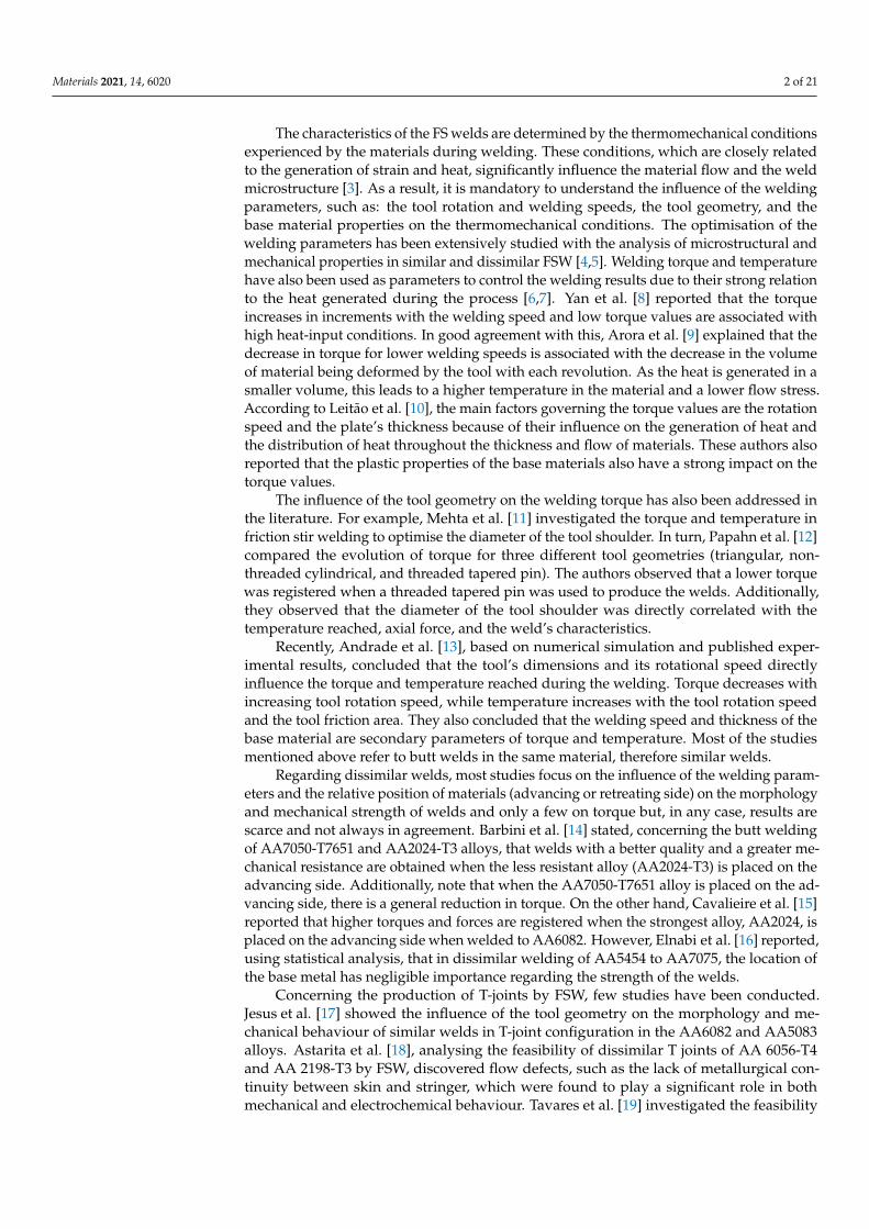
Fatigue specimens were removed transversely to the welding direction, with dimen-sions of 180 × 20 mm (Figure 3). The specimens were machined in a dog-bone shape inorder to encourage failure in the weld region. The flash on the weld surface was removedand the edges were rounded and polished to avoid a concentration of surface stress and ini-tiation of the crack. The load was applied in the skin direction transversely to the weldingdirection, and two fatigue specimens were tested for each load level applied. The fatiguetests were carried out using an Instron servo-hydraulic machine coupled to an Instron FastTrack 8800 acquisition and control system. The stress range varied between 150 to 200 MPawith a frequency of 15–25 Hz according to the load level applied, and the stress ratio wasset to 0.02. The fracture surface of the fatigue specimens was analysed by scanning electronmicroscopy (SEM) using a Zeiss MERLIN field emission scanning electron microscope.
Materials 2021, 14, 6020 7 of 21
Materials 2021, 14, x FOR PEER REVIEW 7 of 21
Figure 3. Fatigue specimen and loading conditions.
3. Results and Discussion
3.1. Welding Torque and Temperature
Figure 4a,b show the average torque and the peak temperature values obtained
during dissimilar welding. The average torque was computed considering only the
steady‐state torque evolution, while the temperature values are peak temperature
measurements performed on the retreating side of the welds. It was found that although
the temperatures reached on the advancing side were higher, the thermocouples placed
on the retreating side were less affected by the passage of the tool. It can be observed in
Figure 4a that the highest torque values were registered in the welds produced with the
progressive pin tools. However, Figure 4b shows that the highest peak temperature values
were also registered in these welds, which does not agree with the conventional torque‐
temperature correlation, that is, when the temperature increases the torque required to
deform the material decreases [10]. The temperature reached in the weld is governed by
the heat input in the process, which depends on the welding parameters, such as the
rotation and welding speeds and axial force of the tool, but also on its geometry and
sticking/sliding conditions [26], specifically, the area of friction between the tool and the
material being welded. In the current study, as the diameter of the shoulder of all the tools
was approximately the same, the difference in the friction area between the tools came
from the pin area. Figure 5a represents the friction area of each tool pin, already shown in
Table 3, while Figure 5b shows the cross‐section area of the stir zone for dissimilar welds.
Figure 4. Process outputs for dissimilar welding: (a) average torque; (b) peak temperature.
Figure 3. Fatigue specimen and loading conditions.
3. Results and Discussion3.1. Welding Torque and Temperature
Figure 4a,b show the average torque and the peak temperature values obtained duringdissimilar welding. The average torque was computed considering only the steady-statetorque evolution, while the temperature values are peak temperature measurements per-formed on the retreating side of the welds. It was found that although the temperaturesreached on the advancing side were higher, the thermocouples placed on the retreating sidewere less affected by the passage of the tool. It can be observed in Figure 4a that the highesttorque values were registered in the welds produced with the progressive pin tools. How-ever, Figure 4b shows that the highest peak temperature values were also registered in thesewelds, which does not agree with the conventional torque-temperature correlation, that is,when the temperature increases the torque required to deform the material decreases [10].The temperature reached in the weld is governed by the heat input in the process, whichdepends on the welding parameters, such as the rotation and welding speeds and axialforce of the tool, but also on its geometry and sticking/sliding conditions [26], specifically,the area of friction between the tool and the material being welded. In the current study, asthe diameter of the shoulder of all the tools was approximately the same, the difference inthe friction area between the tools came from the pin area. Figure 5a represents the frictionarea of each tool pin, already shown in Table 3, while Figure 5b shows the cross-sectionarea of the stir zone for dissimilar welds.
The higher friction area between the progressive pin tools and the material to weld(Figure 5a) promoted an increase of the heat-input during welding, which reduced the flowstress of the material, as Siddiqui et al. [27] mentioned. Although the lower flow stress wasexpected to decrease the torque, progressive pin tools provided an increase in the amount ofmaterial dragged by the tool at each revolution, as the tools’ pin volumes suggest (Table 3)and the weld’s cross sections in Figure 5b show, and therefore the torque increased. Therewas no significant difference in terms of torque and even peak temperatures between theprogressive pin tools (PPP and PTP) (Figure 4) because their friction areas are very similarand led to welds with similar cross-sections (Figure 5).
It can also be seen in Figure 4a that the average torque in dissimilar welding dependson the position of the base material, especially for single-pin tools (PP and TP). Highertorque values tended to be registered when AA5083 was welded as the skin, although thejustification was less clear when looking at the cross section of the stir zone (Figure 5b).The base materials have quite different mechanical behaviour under high temperature andstrain rate conditions. While AA6082 experiences strong softening under high temperatureand strain rate conditions, AA5083 presents steady flow behaviour at high temperatures,but it is sensitive to moderate hardening at high strain rates [20,28]. When conventionaltools are used, the shoulder-driven volume is much larger than the pin-driven volume.As the shoulder mostly contacts with the skin plate, higher flow stresses are experiencedduring the welding of the 56 series, which increases the torque. As the differences in the

Materials 2021, 14, 6020 8 of 21
shoulder and pin-driven volumes decrease in dissimilar welding with the progressive pintools, the effect of the position of the base material on the torque is less intense.
Materials 2021, 14, x FOR PEER REVIEW 7 of 21
Figure 3. Fatigue specimen and loading conditions.
3. Results and Discussion
3.1. Welding Torque and Temperature
Figure 4a,b show the average torque and the peak temperature values obtained
during dissimilar welding. The average torque was computed considering only the
steady‐state torque evolution, while the temperature values are peak temperature
measurements performed on the retreating side of the welds. It was found that although
the temperatures reached on the advancing side were higher, the thermocouples placed
on the retreating side were less affected by the passage of the tool. It can be observed in
Figure 4a that the highest torque values were registered in the welds produced with the
progressive pin tools. However, Figure 4b shows that the highest peak temperature values
were also registered in these welds, which does not agree with the conventional torque‐
temperature correlation, that is, when the temperature increases the torque required to
deform the material decreases [10]. The temperature reached in the weld is governed by
the heat input in the process, which depends on the welding parameters, such as the
rotation and welding speeds and axial force of the tool, but also on its geometry and
sticking/sliding conditions [26], specifically, the area of friction between the tool and the
material being welded. In the current study, as the diameter of the shoulder of all the tools
was approximately the same, the difference in the friction area between the tools came
from the pin area. Figure 5a represents the friction area of each tool pin, already shown in
Table 3, while Figure 5b shows the cross‐section area of the stir zone for dissimilar welds.
Figure 4. Process outputs for dissimilar welding: (a) average torque; (b) peak temperature. Figure 4. Process outputs for dissimilar welding: (a) average torque; (b) peak temperature.
Materials 2021, 14, x FOR PEER REVIEW 8 of 21
Figure 5. (a) Friction area of each tool pin; (b) cross section area of the stir zone according to the tool
geometry and welding speed.
The higher friction area between the progressive pin tools and the material to weld
(Figure 5a) promoted an increase of the heat‐input during welding, which reduced the
flow stress of the material, as Siddiqui et al. [27] mentioned. Although the lower flow
stress was expected to decrease the torque, progressive pin tools provided an increase in
the amount of material dragged by the tool at each revolution, as the tools’ pin volumes
suggest (Table 3) and the weld’s cross sections in Figure 5b show, and therefore the torque
increased. There was no significant difference in terms of torque and even peak tempera‐
tures between the progressive pin tools (PPP and PTP) (Figure 4) because their friction
areas are very similar and led to welds with similar cross‐sections (Figure 5).
It can also be seen in Figure 4a that the average torque in dissimilar welding depends
on the position of the base material, especially for single‐pin tools (PP and TP). Higher
torque values tended to be registered when AA5083 was welded as the skin, although the
justification was less clear when looking at the cross section of the stir zone (Figure 5b).
The base materials have quite different mechanical behaviour under high temperature
and strain rate conditions. While AA6082 experiences strong softening under high tem‐
perature and strain rate conditions, AA5083 presents steady flow behaviour at high tem‐
peratures, but it is sensitive to moderate hardening at high strain rates [20,28]. When con‐
ventional tools are used, the shoulder‐driven volume is much larger than the pin‐driven
volume. As the shoulder mostly contacts with the skin plate, higher flow stresses are ex‐
perienced during the welding of the 56 series, which increases the torque. As the differ‐
ences in the shoulder and pin‐driven volumes decrease in dissimilar welding with the
progressive pin tools, the effect of the position of the base material on the torque is less
intense.
The average torque in dissimilar welding also increases with the traverse speed (Fig‐
ure 4a). Similar findings were also reported by Banik et al. [29] and Aldanondo et al. [30],
although Arora et al. [9] stated that torque is little influenced by welding speed. In most
of the cases, the evolution of the temperature with the traverse speed supports the varia‐
tion in torque, that is, the peak temperature decreases with the increase of welding speed
(Figure 4b), and the base material presents higher material flow stresses [8], thus requiring
greater torque. However, Figure 4b also shows that, in the case of the 65‐weld series per‐
formed with the pyramidal pin tool (PP) and the tapered threaded pin tool (TP), an in‐
crease in the peak temperature occurred with the increase in the welding speed from 60
mm/min to 120 mm/min. This happened in the first case because there was an increase in
tool penetration depth of 0.1 mm, and in the second by 0.5 mm, when the welding speed
was changed from 60 mm/min to 120 mm/min. This clearly shows the influence of the tool
penetration depth on the temperature developed in the weld.
Figure 5. (a) Friction area of each tool pin; (b) cross section area of the stir zone according to the tool geometry and weldingspeed.
The average torque in dissimilar welding also increases with the traverse speed(Figure 4a). Similar findings were also reported by Banik et al. [29] and Aldanondo et al. [30],although Arora et al. [9] stated that torque is little influenced by welding speed. In most ofthe cases, the evolution of the temperature with the traverse speed supports the variationin torque, that is, the peak temperature decreases with the increase of welding speed(Figure 4b), and the base material presents higher material flow stresses [8], thus requiringgreater torque. However, Figure 4b also shows that, in the case of the 65-weld seriesperformed with the pyramidal pin tool (PP) and the tapered threaded pin tool (TP), anincrease in the peak temperature occurred with the increase in the welding speed from60 mm/min to 120 mm/min. This happened in the first case because there was an increasein tool penetration depth of 0.1 mm, and in the second by 0.5 mm, when the welding speedwas changed from 60 mm/min to 120 mm/min. This clearly shows the influence of thetool penetration depth on the temperature developed in the weld.
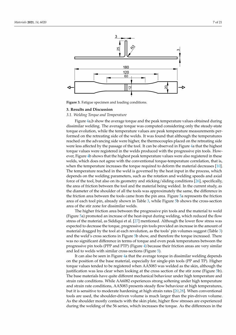
Figure 6 illustrates the temperature variation with welding speed, measured on theretreating side, for welds performed with the progressive conical threaded tool (PTP) better.This figure also shows that in combination 56, higher peak temperatures were reached
Materials 2021, 14, 6020 9 of 21
than in 65, although the recorded torque values were also higher (Figure 4a). This showsthat the evolution of the torque cannot be interpreted exclusively based on the heat-inputconditions; the tool/material contact conditions (sticking/sliding) [9], volume of materialaround the pin, and thermomechanical behaviour of the materials must also be considered.
Materials 2021, 14, x FOR PEER REVIEW 9 of 21
Figure 6 illustrates the temperature variation with welding speed, measured on the
retreating side, for welds performed with the progressive conical threaded tool (PTP) bet‐
ter. This figure also shows that in combination 56, higher peak temperatures were reached
than in 65, although the recorded torque values were also higher (Figure 4a). This shows
that the evolution of the torque cannot be interpreted exclusively based on the heat‐input
conditions; the tool/material contact conditions (sticking/sliding) [9], volume of material
around the pin, and thermomechanical behaviour of the materials must also be consid‐
ered.
The tri‐dissimilar welds were carried out with the progressive threaded pin tool
(PTP), but varying the position of the skin plates (AA5083 and AA2017), either on the
advancing side or on the retreating side, and with welding speeds of 60 mm/min and 230
mm/min. The average torque of the tri‐dissimilar welds was also found to depend on the
position of the base material, as the highest torque values were registered for the 265
welds (Figure 7a), that is, when the strongest material was placed on the advancing side.
Figure 7b shows that the peak temperature difference was about 50 °C for the lowest weld‐
ing speed, and this difference tended to increase for the highest speed. However, the con‐
ventional torque‐temperature correlation was not observed in this case. The higher peak
temperatures were not registered in the welds for which the lower torque values were
measured (Figure 7), which confirms that torque is not exclusively governed by the heat‐
input during welding. Welding with AA2017 on the advancing side resulted in higher
average torque values, even for welds produced under higher heat‐input conditions.
Figure 6. Thermal cycles measured on the retreating side of welds produced with different welding
speeds and combination of materials.
Figure 6. Thermal cycles measured on the retreating side of welds produced with different weldingspeeds and combination of materials.
The tri-dissimilar welds were carried out with the progressive threaded pin tool (PTP),but varying the position of the skin plates (AA5083 and AA2017), either on the advancingside or on the retreating side, and with welding speeds of 60 mm/min and 230 mm/min.The average torque of the tri-dissimilar welds was also found to depend on the position ofthe base material, as the highest torque values were registered for the 265 welds (Figure 7a),that is, when the strongest material was placed on the advancing side. Figure 7b showsthat the peak temperature difference was about 50 ◦C for the lowest welding speed, andthis difference tended to increase for the highest speed. However, the conventional torque-temperature correlation was not observed in this case. The higher peak temperatures werenot registered in the welds for which the lower torque values were measured (Figure 7),which confirms that torque is not exclusively governed by the heat-input during welding.Welding with AA2017 on the advancing side resulted in higher average torque values, evenfor welds produced under higher heat-input conditions.
Figure 7a also shows that the increase in welding speed increased torque, whichis compatible with the reduction in peak temperature registered for any of the materialcombinations studied (Figure 7b). The increase in torque is also compatible with theincrease in the specific volume of the material moved by the tool (V), this being given bythe product of the cross section (A) by the welding speed (v) (V = Av). In fact, althoughthe weld’s cross section (A) suffered a slight reduction with increasing speed (Figure 8), Vgreatly increased due to the large increase in v.

Materials 2021, 14, 6020 10 of 21
Materials 2021, 14, x FOR PEER REVIEW 10 of 21
Figure 7. Process outputs for tri‐dissimilar welding: (a) average torque; (b) peak temperature.
Figure 7a also shows that the increase in welding speed increased torque, which is
compatible with the reduction in peak temperature registered for any of the material com‐
binations studied (Figure 7b). The increase in torque is also compatible with the increase
in the specific volume of the material moved by the tool (V), this being given by the prod‐
uct of the cross section (A) by the welding speed (v) (V = Av). In fact, although the weld’s
cross section (A) suffered a slight reduction with increasing speed (Figure 8), V greatly
increased due to the large increase in v.
Figure 8. (a) Cross section areas of tri‐dissimilar welds; (b) 562TP‐60 (A = 52 mm2); (c) 265TP60 (A =
49 mm2).
3.2. Weld Morphology
3.2.1. Dissimilar Welds
Macrographs of the transverse cross‐section of the dissimilar welds in the 65 and 56
series are shown in Figure 9, which illustrates the welds produced with varying pin pro‐
files. Welds of Figure 9a–h were produced with threaded pin (TP) and pyramidal pin (PP)
tools. It can be observed that the use of simple pin tools (TP and PP) promoted the for‐
mation of large void and/or lack of bonding (kissing bond) defects in the stir region of the
dissimilar welds, regardless of the welding speed and the relative position of the base
materials. Furthermore, the figures also show that larger defects were formed by a weld‐
ing speed of 60 mm/min with a TP tool and when positioning the AA6082 alloy as the skin
Figure 7. Process outputs for tri-dissimilar welding: (a) average torque; (b) peak temperature.
Materials 2021, 14, x FOR PEER REVIEW 10 of 21
Figure 7. Process outputs for tri‐dissimilar welding: (a) average torque; (b) peak temperature.
Figure 7a also shows that the increase in welding speed increased torque, which is
compatible with the reduction in peak temperature registered for any of the material com‐
binations studied (Figure 7b). The increase in torque is also compatible with the increase
in the specific volume of the material moved by the tool (V), this being given by the prod‐
uct of the cross section (A) by the welding speed (v) (V = Av). In fact, although the weld’s
cross section (A) suffered a slight reduction with increasing speed (Figure 8), V greatly
increased due to the large increase in v.
Figure 8. (a) Cross section areas of tri‐dissimilar welds; (b) 562TP‐60 (A = 52 mm2); (c) 265TP60 (A =
49 mm2).
3.2. Weld Morphology
3.2.1. Dissimilar Welds
Macrographs of the transverse cross‐section of the dissimilar welds in the 65 and 56
series are shown in Figure 9, which illustrates the welds produced with varying pin pro‐
files. Welds of Figure 9a–h were produced with threaded pin (TP) and pyramidal pin (PP)
tools. It can be observed that the use of simple pin tools (TP and PP) promoted the for‐
mation of large void and/or lack of bonding (kissing bond) defects in the stir region of the
dissimilar welds, regardless of the welding speed and the relative position of the base
materials. Furthermore, the figures also show that larger defects were formed by a weld‐
ing speed of 60 mm/min with a TP tool and when positioning the AA6082 alloy as the skin
Figure 8. (a) Cross section areas of tri-dissimilar welds; (b) 562TP-60 (A = 52 mm2); (c) 265TP60 (A = 49 mm2).
3.2. Weld Morphology3.2.1. Dissimilar Welds
Macrographs of the transverse cross-section of the dissimilar welds in the 65 and56 series are shown in Figure 9, which illustrates the welds produced with varying pinprofiles. Welds of Figure 9a–h were produced with threaded pin (TP) and pyramidal pin(PP) tools. It can be observed that the use of simple pin tools (TP and PP) promoted theformation of large void and/or lack of bonding (kissing bond) defects in the stir regionof the dissimilar welds, regardless of the welding speed and the relative position of thebase materials. Furthermore, the figures also show that larger defects were formed bya welding speed of 60 mm/min with a TP tool and when positioning the AA6082 alloyas the skin (Figure 9e). It was observed that the defect size tended to increase with aPP tool at the higher welding speed of 120 mm/min. By increasing the welding speed,the heat input per unit weld length decreased, more mm per tool rotation, which led topoor material plasticization and thermo-mechanical interaction between the tool and thematerial flow. For a threaded-pin tool, the inverse occurs. Sun and Wu [31] stated that

Materials 2021, 14, 6020 11 of 21
threads improve the material flow close to the pin tip and broaden the thermomechanicallyaffected zone. Figure 5b shows that the welds made with a threaded pin tool and a weldingspeed of 60 mm/min have a larger cross-sectional area than those made with a pyramidalpin, but this weld is the one with the largest cavity (Figure 9e). Discounting the cavityarea substantially reduces the cross-sectional area of the weld, and hence the volume ofmaterial moved by the tool. On the other hand, pins with flat features produce a greatervolume of material moved [32], which is what is observed in the welds performed with thepyramid tool (Figure 5b). When positioning the AA5083 alloy as the skin (56 series), a slightimprovement in the dimensions of the defect was observed, but not enough to remove thedefects. Furthermore, defects, either cavities or lack of bonding, occur in the fillet zone,which means that the volume of material moved by the tool in the zone is insufficient toprevent the formation of defects. The tool geometry influenced the location of the defects.Defects caused by the PP were located further away from the shoulder zone interaction.
However, regardless of the specific design, it can be inferred that tools with a simplepin are not a viable solution for producing dissimilar T welds in AA5082 and AA6082, asthese tools do not provide the intense mixing of the materials required to achieve non-defective joints. The cavity observed in dissimilar welds is related with a lower heat input,which results in insufficient plasticised material being deposited behind the tool [33].
On the other hand, the tools with a progressive pin (PPP and PTP), and regardless ofthe location of the base materials, allowed the production of welds without defects andwith the formation of large onion-ring structures (Figure 9i–p). The exception is Figure 9o,which has a small void on the retreating side due to insufficient tool sinking. The defectfree welds registered with progressive pin tools have two main reasons. First, the localsoftening of the materials makes the vertical material flow more efficient, promoting theformation of intercalated layers of the welded materials and abolishing the formation ofdefects. Figure 4b shows that the peak temperatures induced by these tools are higher thanthose of single-pin tools.
The second reason is related to differences in the volume of material moved by thetools. The pyramid progressive pin tool (PPP) has a static volume 3.4 times greater than thepyramid pin tool (PP) and provided about 1.4 times larger weld cross sections for welds65–60. The progressive threaded pin tool (PTP) has 2.4 times the static pin volume of thetapered threaded pin (TP) and provided about 1.4 times the weld sections for the sametype of welds.
Therefore, the progressive pin tools promote much greater dragging of materialaround the pin during the welding process, increasing the torque and heat input andreducing the likelihood of the occurrence of defects such as voids and/or lack of bonding.
3.2.2. Tri-Dissimilar Welds
From the macrographs of tri-dissimilar welds, which are shown in Figure 10, it can beobserved that sound macrostructures were achieved by welding with a traverse speed of60 mm/min. In fact, regardless of the position of the base material, the cross-sections weredefect-free and large onion-ring structures were formed in the weld nugget, as illustratedin Figure 10a,b. However, the figures also show that the increase in the traverse speed to230 mm/min promoted the formation of defective structures in the nugget and removedthe onion-ring structures (Figure 10c,d), which were replaced by chaotic mixing patterns.The detrimental effect of high traverse speed values on the morphology of welds producedby FSW has already been discussed by Kadian and Biswas [34] for butt joints and byManuel et al. [22] for T-joints.

Materials 2021, 14, 6020 12 of 21Materials 2021, 14, x FOR PEER REVIEW 12 of 21
Figure 9. Cross‐section macrographs of the dissimilar welds for different welding parameters.
The second reason is related to differences in the volume of material moved by the
tools. The pyramid progressive pin tool (PPP) has a static volume 3.4 times greater than
the pyramid pin tool (PP) and provided about 1.4 times larger weld cross sections for
welds 65–60. The progressive threaded pin tool (PTP) has 2.4 times the static pin volume
of the tapered threaded pin (TP) and provided about 1.4 times the weld sections for the
same type of welds.
Therefore, the progressive pin tools promote much greater dragging of material
around the pin during the welding process, increasing the torque and heat input and re‐
ducing the likelihood of the occurrence of defects such as voids and/or lack of bonding.
Figure 9. Cross-section macrographs of the dissimilar welds for different welding parameters.
Figure 10c,d shows that the formation of these defects occurs at the boundary betweenthe skin and the stinger. This is precisely the zone of interaction between the material flowinduced by the cylindrical threaded part of the pin and the flow originated by the conicalthreaded part of the pin, as shown by Manuel et al. [21]. The formation of these defects isdue to the insufficient interaction between these fluxes, caused by less plasticization of thematerials, because the temperatures reached in the zone decrease with the increase in thewelding speed, as shown in Figure 7b. Furthermore, the reduced space between the tooland the dies [21] constrains the upward flow of material induced by the conical threadedpart of the pin.

Materials 2021, 14, 6020 13 of 21
Materials 2021, 14, x FOR PEER REVIEW 13 of 21
3.2.2. Tri‐Dissimilar Welds
From the macrographs of tri‐dissimilar welds, which are shown in Figure 10, it can
be observed that sound macrostructures were achieved by welding with a traverse speed
of 60 mm/min. In fact, regardless of the position of the base material, the cross‐sections
were defect‐free and large onion‐ring structures were formed in the weld nugget, as illus‐
trated in Figure 10a,b. However, the figures also show that the increase in the traverse
speed to 230 mm/min promoted the formation of defective structures in the nugget and
removed the onion‐ring structures (Figure 10c,d), which were replaced by chaotic mixing
patterns. The detrimental effect of high traverse speed values on the morphology of welds
produced by FSW has already been discussed by Kadian and Biswas [34] for butt joints
and by Manuel et al. [22] for T‐joints.
Figure 10. Cross section macrographs of the tri‐dissimilar welds: (a) 562TP‐60‐6.8; (b) 265TP‐60‐7;
(c) 562TP‐230‐7; (d) 265TP‐230‐7.
Figure 10c,d shows that the formation of these defects occurs at the boundary be‐
tween the skin and the stinger. This is precisely the zone of interaction between the mate‐
rial flow induced by the cylindrical threaded part of the pin and the flow originated by
the conical threaded part of the pin, as shown by Manuel et al. [21]. The formation of these
defects is due to the insufficient interaction between these fluxes, caused by less plastici‐
zation of the materials, because the temperatures reached in the zone decrease with the
increase in the welding speed, as shown in Figure 7b. Furthermore, the reduced space
between the tool and the dies [21] constrains the upward flow of material induced by the
conical threaded part of the pin.
3.3. Microstuctures in the Stir Zone
The microstructure of the stir zone results from complex thermomechanical condi‐
tions, with the materials involved subjected to temperatures, degrees of deformation, and
deformation rates that vary with the location in the nugget. Figure 11 illustrates some
details of the stir zone of a 65PP‐60 dissimilar weld. Figure 11a shows a macrograph of
the weld and the location of the details illustrated in the following figures. Figure 11b
shows a detail of zone 1 of the nugget, which illustrates the complexity of the flow of the
two materials in the zone. The observation of these microstructures is difficult due to this
mixing complexity, but mainly because the etchants are not effective simultaneously for
both materials. The areas where grain is visible correspond to the AA6082 alloy, while the
non‐etched areas to AA5083. The figure shows that there was a great grain refinement in
this zone when compared with the base material (AA6082), illustrated in Figure 11d. The
grain in the nugget had an average size of 7.7 + 0.6 μm, while the base material did not
Figure 10. Cross section macrographs of the tri-dissimilar welds: (a) 562TP-60-6.8; (b) 265TP-60-7; (c) 562TP-230-7; (d) 265TP-230-7.
3.3. Microstuctures in the Stir Zone
The microstructure of the stir zone results from complex thermomechanical condi-tions, with the materials involved subjected to temperatures, degrees of deformation, anddeformation rates that vary with the location in the nugget. Figure 11 illustrates somedetails of the stir zone of a 65PP-60 dissimilar weld. Figure 11a shows a macrograph ofthe weld and the location of the details illustrated in the following figures. Figure 11bshows a detail of zone 1 of the nugget, which illustrates the complexity of the flow of thetwo materials in the zone. The observation of these microstructures is difficult due to thismixing complexity, but mainly because the etchants are not effective simultaneously forboth materials. The areas where grain is visible correspond to the AA6082 alloy, while thenon-etched areas to AA5083. The figure shows that there was a great grain refinement inthis zone when compared with the base material (AA6082), illustrated in Figure 11d. Thegrain in the nugget had an average size of 7.7 + 0.6 µm, while the base material did nothave a uniform grain with an average size in the rolling direction of 56.7 + 31.7 µm. Thegrain was, however, not uniform in the nugget, as illustrated in Figure 11c. This figureshows that the grain decreased from about 8.2 µm to 3.2 µm when comparing the right sideof the image with the central area, where very close deformation lines appeared. In thiszone, the grains were very fine and elongated according to the direction of the deformation.In the area to the left of the image, where there seems to have been a lower degree ofdeformation, the recrystallisation [35] provided a more rounded and larger grain, of about7.8 ± 2.9 µm. In the case of dissimilar welds, it is therefore difficult to characterise the grainsize in the stir zone due to the variability that is observed. Changing the tool geometrydid not significantly alter the microstructure in the nugget. Increasing the welding speedfurther refined the grain to values down to 5.7 µm.
Figure 12 illustrates some microstructural details of a weld of the three alloys con-sidered, specifically 562TP-60. Figure 12a gives the location of the details illustrated inFigure 12b,c. Figure 12b corresponds to an onion ring zone, where the fluxes of the threematerials are illustrated. The upper dark bands correspond to AA2017, which is over-etched, the middle band to AA5083, which is not properly etched, and the lower bandto AA6082 that is properly etched. The white zones are zones of interaction between thetwo alloys, which have not been etched. In tri-dissimilar welds, etching is even moredifficult, as conventional reagents behave differently from those used for homogeneouswelds. Figure 12c illustrates the microstructure of a part of the nugget, where the formation

Materials 2021, 14, 6020 14 of 21
of a very refined grain, of about 6 ± 2.7 µm, occurred. The higher temperatures reached inthese welds (Figure 7b) due to the use of a progressive pin tool suggested the formationof coarser grain. The plastic deformation rate must have conditioned this growth, asmentioned above. The increase in welding speed allowed the refinement of the grain in thenugget to values of about 4 µm.
Materials 2021, 14, x FOR PEER REVIEW 14 of 21
have a uniform grain with an average size in the rolling direction of 56.7 + 31.7 μm. The
grain was, however, not uniform in the nugget, as illustrated in Figure 11c. This figure
shows that the grain decreased from about 8.2 μm to 3.2 μm when comparing the right
side of the image with the central area, where very close deformation lines appeared. In
this zone, the grains were very fine and elongated according to the direction of the defor‐
mation. In the area to the left of the image, where there seems to have been a lower degree
of deformation, the recrystallisation [35] provided a more rounded and larger grain, of
about 7.8 ± 2.9 μm. In the case of dissimilar welds, it is therefore difficult to characterise
the grain size in the stir zone due to the variability that is observed. Changing the tool
geometry did not significantly alter the microstructure in the nugget. Increasing the weld‐
ing speed further refined the grain to values down to 5.7 μm.
Figure 11. Stir zone of the 65PP‐60 dissimilar welding: (a) weld cross section; (b–d) microstructure
in Zones 1, 2, and 3.
Figure 12 illustrates some microstructural details of a weld of the three alloys consid‐
ered, specifically 562TP‐60. Figure 12a gives the location of the details illustrated in Figure
12b,c. Figure 12b corresponds to an onion ring zone, where the fluxes of the three materi‐
als are illustrated. The upper dark bands correspond to AA2017, which is over‐etched, the
middle band to AA5083, which is not properly etched, and the lower band to AA6082 that
is properly etched. The white zones are zones of interaction between the two alloys, which
have not been etched. In tri‐dissimilar welds, etching is even more difficult, as conven‐
tional reagents behave differently from those used for homogeneous welds. Figure 12c
illustrates the microstructure of a part of the nugget, where the formation of a very refined
grain, of about 6 ± 2.7 μm, occurred. The higher temperatures reached in these welds (Fig‐
ure 7b) due to the use of a progressive pin tool suggested the formation of coarser grain.
The plastic deformation rate must have conditioned this growth, as mentioned above. The
increase in welding speed allowed the refinement of the grain in the nugget to values of
about 4 μm.
Figure 11. Stir zone of the 65PP-60 dissimilar welding: (a) weld cross section; (b–d) microstructure in Zones 1, 2, and 3.
3.4. Weld Mechanical Behaviour3.4.1. Microhardness
Single-pin tools did not provide sound dissimilar welds, so these welds were notmechanically tested. Progressive pin tools delivered dissimilar welds free of defects, butwhose effect on the mechanical behaviour, for the range of parameters tested, has beenpreviously analysed [22]. Therefore, only the analysis of the mechanical behaviour of thetri-dissimilar welds is presented.
Hardness maps of tri-dissimilar welds are presented in Figure 13, where the advancingand retreating sides are indicated by AS and RS, respectively. Comparing Figure 13a withFigure 13c, which corresponds to welds performed in series 562 with welding speeds of60 mm/min and 230 mm/min, respectively, significant differences can be observed, mainlyin the heat-affected zones on the sides of AA2017 and AA6082. Actually, the weld carriedout with 60 mm/min presents a hardness reduction from 120 HV0.2 to about 80 HV0.2 onthe AA2017 side, in an extension of nearly 13 mm, while for the welding carried out at230 mm/min this reduction extended to about 5 mm. In the stringer (AA6082 side), thedrop in hardness was greater, from about 115 to 60 HV0.2, but to a lesser extent, in the weldperformed at a higher speed. These losses in hardness were expected and have alreadybeen analysed by other authors [36]. A dissolution of strengthening precipitation occurswhen heat-treatable alloys are exposed at higher temperature, which leads to hardness

Materials 2021, 14, 6020 15 of 21
drops in HAZ and TMAZ. The hardness reduction is more notable in AA6082 because itwas in temper T6, although the location of this zone was further away from the shoulderof the tool. Most of the heat is generated by the tool shoulder [37]. In the stir zone, thehardness distribution is heterogeneous due to the combined effect of the dissolution ofhardening precipitates and the mixture of the three alloys. The mix of the three alloys inthe stir zone is very complex, as mentioned in Section 3.3 and illustrated in Figure 12. Onthe AA5083 side, there was a slight hardness variation because the base material had a softtemper.
Materials 2021, 14, x FOR PEER REVIEW 15 of 21
Figure 12. Stir zone microstructures of the 562TP‐60 tri‐dissimilar welding: (a) weld cross section;
(b) and (c) microstructure in Zones 1 and 2.
3.4. Weld Mechanical Behaviour
3.4.1. Microhardness
Single‐pin tools did not provide sound dissimilar welds, so these welds were not
mechanically tested. Progressive pin tools delivered dissimilar welds free of defects, but
whose effect on the mechanical behaviour, for the range of parameters tested, has been
previously analysed [22]. Therefore, only the analysis of the mechanical behaviour of the
tri‐dissimilar welds is presented.
Hardness maps of tri‐dissimilar welds are presented in Figure 13, where the advanc‐
ing and retreating sides are indicated by AS and RS, respectively. Comparing Figure 13a
with Figure 13c, which corresponds to welds performed in series 562 with welding speeds
of 60 mm/min and 230 mm/min, respectively, significant differences can be observed,
mainly in the heat‐affected zones on the sides of AA2017 and AA6082. Actually, the weld
carried out with 60 mm/min presents a hardness reduction from 120 HV0.2 to about 80
HV0.2 on the AA2017 side, in an extension of nearly 13 mm, while for the welding carried
out at 230 mm/min this reduction extended to about 5 mm. In the stringer (AA6082 side),
the drop in hardness was greater, from about 115 to 60 HV0.2, but to a lesser extent, in the
weld performed at a higher speed. These losses in hardness were expected and have al‐
ready been analysed by other authors [36]. A dissolution of strengthening precipitation
occurs when heat‐treatable alloys are exposed at higher temperature, which leads to hard‐
ness drops in HAZ and TMAZ. The hardness reduction is more notable in AA6082 be‐
cause it was in temper T6, although the location of this zone was further away from the
shoulder of the tool. Most of the heat is generated by the tool shoulder [37]. In the stir
zone, the hardness distribution is heterogeneous due to the combined effect of the disso‐
lution of hardening precipitates and the mixture of the three alloys. The mix of the three
alloys in the stir zone is very complex, as mentioned in Section 3.3 and illustrated in Figure
12. On the AA5083 side, there was a slight hardness variation because the base material
had a soft temper.
In case of the series 265 presented in Figure 13b,d, a significant fluctuation of hard‐
ness values, between 71 and 117 HV0.2, was registered in the TMAZ and nugget zone for
Figure 12. Stir zone microstructures of the 562TP-60 tri-dissimilar welding: (a) weld cross section; (b) and (c) microstructurein Zones 1 and 2.
In case of the series 265 presented in Figure 13b,d, a significant fluctuation of hardnessvalues, between 71 and 117 HV0.2, was registered in the TMAZ and nugget zone for 60and 230 mm/min welding speeds. This may be attributed to the complex flow of materialthat results in a heterogeneous mixture of the three materials in the stir zone as shown inthe previous section. In the heat-affected zones the effects are like those recorded for the562 series, although the loss of hardness areas in the stringer of the 265 series are moreextensive. This is compatible with the higher peak temperatures recorded for this weldseries (Figure 7b).
In summary, it was found that the distribution of hardness in the weld is influenced bythe properties of the base materials and their relative position in the joint. When AA2017was on the advancing side, a more significant effect on hardness under the same weldingconditions was registered.

Materials 2021, 14, 6020 16 of 21
Materials 2021, 14, x FOR PEER REVIEW 16 of 21
60 and 230 mm/min welding speeds. This may be attributed to the complex flow of mate‐
rial that results in a heterogeneous mixture of the three materials in the stir zone as shown
in the previous section. In the heat‐affected zones the effects are like those recorded for
the 562 series, although the loss of hardness areas in the stringer of the 265 series are more
extensive. This is compatible with the higher peak temperatures recorded for this weld
series (Figure 7b).
In summary, it was found that the distribution of hardness in the weld is influenced
by the properties of the base materials and their relative position in the joint. When
AA2017 was on the advancing side, a more significant effect on hardness under the same
welding conditions was registered.
Figure 13. Skin and stringer hardness for the 562 and 265 welds: (a) 562TP‐60; (b) 265TP‐60; (c)
562TP‐230; (d) 265TP‐230.
3.4.2. Ultimate Tensile Test
The ultimate tensile strength (UTS) of the tri‐dissimilar welds is shown in Table 6. As
three specimens were tested per weld, the UTS values displayed in the table correspond
to the average of the results of all the specimens tested. The table also shows the fracture
zone and the weld strength efficiency, which was computed through the ratio between
the weld’s UTS and the UTS of the base material with the lowest strength (AA5083). It can
be observed that most of the welds presented efficiency values over 93%, which indicates
that the welding parameters allowed the production of welds with an improved tensile
behaviour. Even so, flow defects were also formed in the nugget of the 562TP‐230 weld,
but they had no effect on its mechanical strength.
The strength efficiency of the 562TP‐230 weld was slightly higher than the efficiency
of the remaining ones. However, as illustrated in Figure 14, which shows the strain distri‐
bution maps obtained by digital image correlation at maximum load, all the specimens
tested failed at the AA5083, regardless of the traverse speed or the position of the base
material. Taking into consideration the efficiency values of the specimens, which are less
than 100%, it can be stated that the welds failed in the heat‐affected zone. The heat input
during welding promoted the slight softening of AA5083, and therefore, the strain was
found to concentrate in this alloy during testing.
Figure 13. Skin and stringer hardness for the 562 and 265 welds: (a) 562TP-60; (b) 265TP-60; (c) 562TP-230; (d) 265TP-230.
3.4.2. Ultimate Tensile Test
The ultimate tensile strength (UTS) of the tri-dissimilar welds is shown in Table 6. Asthree specimens were tested per weld, the UTS values displayed in the table correspondto the average of the results of all the specimens tested. The table also shows the fracturezone and the weld strength efficiency, which was computed through the ratio between theweld’s UTS and the UTS of the base material with the lowest strength (AA5083). It canbe observed that most of the welds presented efficiency values over 93%, which indicatesthat the welding parameters allowed the production of welds with an improved tensilebehaviour. Even so, flow defects were also formed in the nugget of the 562TP-230 weld,but they had no effect on its mechanical strength.
Table 6. Tensile properties of the welds.
Weld UTS [MPa] Strength Efficiency [%] Zone of Fracture
562TP-60 295.7 93.7 HAZ (AA5083)
562TP-230 304.4 96.1 HAZ (AA5083)
265TP-60 295.6 93.2 HAZ (AA5083)
265TP-230 263.2 82.8 HAZ (AA5083)
The strength efficiency of the 562TP-230 weld was slightly higher than the efficiencyof the remaining ones. However, as illustrated in Figure 14, which shows the straindistribution maps obtained by digital image correlation at maximum load, all the specimenstested failed at the AA5083, regardless of the traverse speed or the position of the basematerial. Taking into consideration the efficiency values of the specimens, which are lessthan 100%, it can be stated that the welds failed in the heat-affected zone. The heat inputduring welding promoted the slight softening of AA5083, and therefore, the strain wasfound to concentrate in this alloy during testing.

Materials 2021, 14, 6020 17 of 21
Materials 2021, 14, x FOR PEER REVIEW 17 of 21
Table 6. Tensile properties of the welds.
Weld UTS [MPa] Strength Efficiency [%] Zone of Fracture
562TP‐60 295.7 93.7 HAZ (AA5083)
562TP‐230 304.4 96.1 HAZ (AA5083)
265TP‐60 295.6 93.2 HAZ (AA5083)
265TP‐230 263.2 82.8 HAZ (AA5083)
Figure 14. Strain distribution maps: (a) 562TP‐60; (b) 265TP‐60; (c) 562TP‐230; (d) 265TP‐230.
3.4.3. Fatigue Tests
Figure 15 shows the results of the fatigue tests for the tri‐dissimilar welds and
AA5083 base material. Horizontal arrows in the graph represent that the fatigue speci‐
mens did not break after more than half a million cycles. The red curve is shown in dashed
lines for this reason. From the figure, it can be observed that all the welds presented a
lower fatigue strength than the base material.
Although FSW is a solid‐state technology, in which the heat generation is lower than
in the conventional welding processes, the material strength was affected by the welding
thermal cycle and, consequently, the fatigue behaviour of the welds was conditioned,
even for the non‐defective joints. However, regardless of the position of the base material,
the fatigue behaviour of the welds produced with 60 mm/min, which were free of defects
(Figure 10a), was better than that of the welds produced with a higher traverse speed. The
fatigue behaviour of the welds produced with a lower traverse speed, which were found
to fracture in the HAZ (AA5083 side), only decreased 10% (265TP‐60) and 13% (562TP‐60)
at 106 cycles when compared with the base material (AA5083). Therefore, the 265 weld
series has slightly better fatigue strength than the 562 series. On the other hand, the fatigue
strength of the welds produced with a traverse speed of 230 mm/min decreased 27%
(562TP‐230) and 47% (256TP‐230). In good agreement with this, the fracture of these welds
occurred in the nugget, where flow defects were observed (Figure 10c,d). Specifically, the
flow defects identified in the 265TP‐230 weld were formed near the fillet region, which
seriously conditioned the fatigue behaviour of this weld. In turn, the defects formed in the
562PTP‐230 weld, despite not affecting the weld tensile behaviour, which was the best
among the different welds, strongly conditioned the fatigue behaviour. In fact, the pres‐
ence of defects in these welds is crucial [20,38].
Figure 14. Strain distribution maps: (a) 562TP-60; (b) 265TP-60; (c) 562TP-230; (d) 265TP-230.
3.4.3. Fatigue Tests
Figure 15 shows the results of the fatigue tests for the tri-dissimilar welds and AA5083base material. Horizontal arrows in the graph represent that the fatigue specimens did notbreak after more than half a million cycles. The red curve is shown in dashed lines for thisreason. From the figure, it can be observed that all the welds presented a lower fatiguestrength than the base material.
Materials 2021, 14, x FOR PEER REVIEW 18 of 21
Figure 15. Fatigue S‐N curves obtained for the tri‐dissimilar welds and the AA5083 base material.
Table 7 presents the equations that describe the S‐N curves obtained from the series
of welds illustrated in Figure 15. The slope “m” indicates the prevalence of the initiation
of the crack and propagation until fracture. The fatigue strength values were determined
at one million cycles. The results indicate that welds with higher value of the factor “m”
present better fatigue resistance such the welds 562‐60 and 265‐60. The curves of the welds
performed at the highest speed showed greater dispersion, see R2, due to the presence of
defects, as mentioned below.
Table 7. Equations of S‐N curves for fatigue strength at 106 cycles.
Series Line Equation Fatigue Strength at 106 Cycles (MPa) Slope “m” R2
562TP‐60 σ = 537.98 N−0.09 155.16 11.11 0.79
562TP‐230 σ = 692.67 N−0.127 119.82 7.87 0.66
265TP‐60 σ = 554.29 N−0.09 159.86 11.11 0.78
265TP‐230 σ = 365.6 N−0.1 91.39 9.90 0.55
AA5083 σ = 653.15 N−0.095 175.80 10.53 0.89
The results of the fractographic analyses performed on the fatigue specimens are
shown in Figure 16. From the figure, it can be observed that the welds produced with a
lower traverse speed presented a ductile fracture (Figure 16a,c), which is in good agree‐
ment with the better fatigue behaviour of these welds. Specifically, the detail highlighted
on the fracture surface of the 562TP‐60 weld (Figure 16a) allows us to observe the striation
pattern associated with the crack growth. The high fatigue lives for the 562TP‐60 welds of
802,067 cycles is clear evidence of the lack of defects in these welds.
Regarding the welds produced with a higher welding speed (Figure 16b,d), defects
were observed on the fracture surfaces, which, as reported above, limited the fatigue be‐
haviour of these joints. Although the stress range applied was low (120 and 140 MPa), the
specimens fractured with a very low number of cycles of 54,421 and 265,159, respectively.
Figure 15. Fatigue S-N curves obtained for the tri-dissimilar welds and the AA5083 base material.
Although FSW is a solid-state technology, in which the heat generation is lower thanin the conventional welding processes, the material strength was affected by the weldingthermal cycle and, consequently, the fatigue behaviour of the welds was conditioned, evenfor the non-defective joints. However, regardless of the position of the base material, thefatigue behaviour of the welds produced with 60 mm/min, which were free of defects(Figure 10a), was better than that of the welds produced with a higher traverse speed. Thefatigue behaviour of the welds produced with a lower traverse speed, which were found tofracture in the HAZ (AA5083 side), only decreased 10% (265TP-60) and 13% (562TP-60)at 106 cycles when compared with the base material (AA5083). Therefore, the 265 weldseries has slightly better fatigue strength than the 562 series. On the other hand, the fatiguestrength of the welds produced with a traverse speed of 230 mm/min decreased 27%(562TP-230) and 47% (256TP-230). In good agreement with this, the fracture of these welds

Materials 2021, 14, 6020 18 of 21
occurred in the nugget, where flow defects were observed (Figure 10c,d). Specifically, theflow defects identified in the 265TP-230 weld were formed near the fillet region, whichseriously conditioned the fatigue behaviour of this weld. In turn, the defects formed inthe 562PTP-230 weld, despite not affecting the weld tensile behaviour, which was the bestamong the different welds, strongly conditioned the fatigue behaviour. In fact, the presenceof defects in these welds is crucial [20,38].
Table 7 presents the equations that describe the S-N curves obtained from the seriesof welds illustrated in Figure 15. The slope “m” indicates the prevalence of the initiationof the crack and propagation until fracture. The fatigue strength values were determinedat one million cycles. The results indicate that welds with higher value of the factor “m”present better fatigue resistance such the welds 562-60 and 265-60. The curves of the weldsperformed at the highest speed showed greater dispersion, see R2, due to the presence ofdefects, as mentioned below.
Table 7. Equations of S-N curves for fatigue strength at 106 cycles.
Series Line Equation Fatigue Strength at 106 Cycles (MPa) Slope “m” R2
562TP-60 σ = 537.98 N−0.09 155.16 11.11 0.79
562TP-230 σ = 692.67 N−0.127 119.82 7.87 0.66
265TP-60 σ = 554.29 N−0.09 159.86 11.11 0.78
265TP-230 σ = 365.6 N−0.1 91.39 9.90 0.55
AA5083 σ = 653.15 N−0.095 175.80 10.53 0.89
The results of the fractographic analyses performed on the fatigue specimens areshown in Figure 16. From the figure, it can be observed that the welds produced with alower traverse speed presented a ductile fracture (Figure 16a,c), which is in good agreementwith the better fatigue behaviour of these welds. Specifically, the detail highlighted onthe fracture surface of the 562TP-60 weld (Figure 16a) allows us to observe the striationpattern associated with the crack growth. The high fatigue lives for the 562TP-60 welds of802,067 cycles is clear evidence of the lack of defects in these welds.
Regarding the welds produced with a higher welding speed (Figure 16b,d), defectswere observed on the fracture surfaces, which, as reported above, limited the fatiguebehaviour of these joints. Although the stress range applied was low (120 and 140 MPa), thespecimens fractured with a very low number of cycles of 54,421 and 265,159, respectively.
Materials 2021, 14, x FOR PEER REVIEW 19 of 21
Figure 16. Fracture surfaces of the fatigue‐tested specimens: (a) 562TP‐60, (b) 562TP‐230, (c) 265TP‐
60, (d) 265TP‐230.
4. Conclusions
The current investigation analysed the influence of tool geometry, process parame‐
ters, and position of the materials on the temperature, torque, and quality of the weld of
two and tri‐dissimilar aluminium alloys. The following conclusions were drawn:
Tools with a single pin, whether pyramidal or tapered threaded, generate lower peak
temperature and torque than tools with a progressive pin. This is caused by the
smaller friction area and smaller volume of material moved by the single pin tools;
Placing the stronger alloy on the advancing side leads to higher welding temperature
and torque, while increasing the welding speed reduces the peak temperature but
increases the torque used;
Single‐pin tools do not provide sound welds, unlike progressive pin tools, and this
is related to the difference in the temperature and volume of material dragged by the
different tools;
The nugget of the welds has a very refined, but not uniform, grain structure whose
size is conditioned by the heat input, but also by the way in which the local plastic
deformation of the materials occurs;
The increase in welding speed causes the appearance of defects in tri‐dissimilar
welds, even when using a tool with a progressive pin, which causes a reduction in
fatigue strength, especially when the more resistant alloy is placed on the advancing
side.
Author Contributions: Conceptualisation, A.L.; methodology, A.L. and J.D.C.; investigation, N.M.,
I.G., R.M.L. and D.B.; writing—original draft preparation, A.L., I.G., N.M. and R.M.L.; writing—
review and editing, N.M., I.G. and R.M.L.; supervision, A.L.; project administration, A.L.; funding
acquisition, A.L. All authors have read and agreed to the published version of the manuscript.
Funding: This research was funded by FEDER and FCT, as indicated in the Acknowledgements.
Institutional Review Board Statement: Not applicable.
Informed Consent Statement: Not applicable.
Data Availability Statement: The data presented in this study are available on reasonable request
from the corresponding author.
Figure 16. Fracture surfaces of the fatigue-tested specimens: (a) 562TP-60, (b) 562TP-230, (c) 265TP-60,(d) 265TP-230.

Materials 2021, 14, 6020 19 of 21
4. Conclusions
The current investigation analysed the influence of tool geometry, process parameters,and position of the materials on the temperature, torque, and quality of the weld of twoand tri-dissimilar aluminium alloys. The following conclusions were drawn:
• Tools with a single pin, whether pyramidal or tapered threaded, generate lower peaktemperature and torque than tools with a progressive pin. This is caused by thesmaller friction area and smaller volume of material moved by the single pin tools;
• Placing the stronger alloy on the advancing side leads to higher welding temperatureand torque, while increasing the welding speed reduces the peak temperature butincreases the torque used;
• Single-pin tools do not provide sound welds, unlike progressive pin tools, and this isrelated to the difference in the temperature and volume of material dragged by thedifferent tools;
• The nugget of the welds has a very refined, but not uniform, grain structure whosesize is conditioned by the heat input, but also by the way in which the local plasticdeformation of the materials occurs;
• The increase in welding speed causes the appearance of defects in tri-dissimilar welds,even when using a tool with a progressive pin, which causes a reduction in fatiguestrength, especially when the more resistant alloy is placed on the advancing side.
Author Contributions: Conceptualisation, A.L.; methodology, A.L. and J.D.C.; investigation, N.M.,I.G., R.M.L. and D.B.; writing—original draft preparation, A.L., I.G., N.M. and R.M.L.; writing—review and editing, N.M., I.G. and R.M.L.; supervision, A.L.; project administration, A.L.; fundingacquisition, A.L. All authors have read and agreed to the published version of the manuscript.
Funding: This research was funded by FEDER and FCT, as indicated in the Acknowledgements.
Institutional Review Board Statement: Not applicable.
Informed Consent Statement: Not applicable.
Data Availability Statement: The data presented in this study are available on reasonable requestfrom the corresponding author.
Acknowledgments: This research is sponsored by FEDER funds through the program COMPETE–Programa Operacional Factores de Competitividade–and by national funds through FCT–Fundaçãopara a Ciência e a Tecnologia, under the project UIDB/00285/2020. The author N. Manuel issupported by Ministério das Pescas de Angola. The financial support is gratefully acknowledged.The authors would also like to thank to Bernardes, who provided valuable assistance in specimenspreparation.
Conflicts of Interest: The authors declare no conflict of interest.
References1. Kah, P.; Rajan, R.; Martikainen, J.; Suoranta, R. Investigation of weld defects in friction-stir welding and fusion welding of
aluminium alloys. Int. J. Mech. Mater. Eng. 2015, 10, 26. [CrossRef]2. Choi, W.J.; Morrow, J.D.; Pfefferkorn, F.E.; Zinn, M.R. The Effects of Welding Parameters and Backing Plate Diffusivity on Energy
Consumption in Friction Stir Welding. Procedia Manuf. 2017, 10, 382–391. [CrossRef]3. Khan, N.K.; Bajaj, D.; Siddiquee, A.N.; Khan, Z.A.; Abidi, M.H.; Umer, U.; Alkhalefah, H. Investigation on Effect of Strain Rate
and Heat Generation on Traverse Force in FSW of Dissimilar Aerospace Grade Aluminium Alloys. Materials 2019, 12, 1641.[CrossRef]
4. Zhang, Y.; Sato, Y.S.; Kokawa, H.; Park, S.H.C.; Hirano, S. Grain structure and microtexture in friction stir welded commercialpurity titanium. Sci. Technol. Weld. Join. 2010, 15, 500–505. [CrossRef]
5. Derazkola, H.A.; Simchi, A. An investigation on the dissimilar friction stir welding of T-joints between AA5754 aluminum alloyand poly(methyl methacrylate). Thin-Walled Struct. 2019, 135, 376–384. [CrossRef]
6. Lambiase, F.; Paoletti, A.; Di Ilio, A. Forces and temperature variation during friction stir welding of aluminum alloy AA6082-T6.Int. J. Adv. Manuf. Technol. 2018, 99, 337–346. [CrossRef]
7. Sreenivas, P.; Anil Kumar, R.; Sreejith, P.S. Effect of applied axial force on FSW of AA 6082-T6 aluminium alloys. Int. J. Mech. Eng.Technol. 2017, 8, 88–99.
Materials 2021, 14, 6020 20 of 21
8. Yan, J.; Sutton, M.A.; Reynolds, A.P. Process-structure-property relationships for nugget and heat affected zone regions ofAA2524-T351 friction stir welds. Sci. Technol. Weld. Join. 2005, 10, 725–736. [CrossRef]
9. Arora, A.; Nandan, R.; Reynolds, A.P.; DebRoy, T. Torque, power requirement and stir zone geometry in friction stir weldingthrough modeling and experiments. Scr. Mater. 2009, 60, 13–16. [CrossRef]
10. Leitão, C.; Louro, R.; Rodrigues, D.M. Using torque sensitivity analysis in accessing Friction Stir Welding/Processing conditions.J. Mater. Process. Technol. 2012, 212, 2051–2057. [CrossRef]
11. Mehta, M.; Chatterjee, K.; De, A. Monitoring torque and traverse force in friction stir welding from input electrical signatures ofdriving motors. Sci. Technol. Weld. Join. 2013, 18, 191–197. [CrossRef]
12. Papahn, H.; Bahemmat, P.; Haghpanahi, M.; Pour Aminaie, I. Effect of friction stir welding tool on temperature, applied forcesand weld quality. IET Sci. Meas. Technol. 2015, 9, 475–484. [CrossRef]
13. Andrade, D.G.; Leitão, C.; Dialami, N.; Chiumenti, M.; Rodrigues, D.M. Modelling torque and temperature in friction stir weldingof aluminium alloys. Int. J. Mech. Sci. 2020, 182, 105725. [CrossRef]
14. Barbini, A.; Carstensen, J.; Dos Santos, J.F. Influence of Alloys Position, Rolling and Welding Directions on Properties ofAA2024/AA7050 Dissimilar Butt Weld Obtained by Friction Stir Welding. Metals 2018, 8, 202. [CrossRef]
15. Cavaliere, P.; De Santis, A.; Panella, F.; Squillace, A. Effect of welding parameters on mechanical and microstructural properties ofdissimilar AA6082–AA2024 joints produced by friction stir welding. Mater. Des. 2009, 30, 609–616. [CrossRef]
16. Abd Elnabi, M.M.; Elshalakany, A.B.; Abdel-Mottaleb, M.M.; Osman, T.A.; El Mokadem, A. Influence of friction stir weldingparameters on metallurgical and mechanical properties of dissimilar AA5454–AA7075 aluminum alloys. J. Mater. Res. Technol.2019, 8, 1684–1693. [CrossRef]
17. Jesus, J.S.; Costa, J.M.; Loureiro, A.; Ferreira, J.M. Assessment of friction stir welding aluminium T-joints. J. Mater. Process. Technol.2018, 255, 387–399. [CrossRef]
18. Astarita, A.; Squillace, A.; Scala, A.; Prisco, A. On the Critical Technological Issues of Friction Stir Welding T-Joints of DissimilarAluminum Alloys. J. Mater. Eng. Perform. 2012, 21, 1763–1771. [CrossRef]
19. -Tavares, S.M.O.; Castro, R.A.S.; Richter Trummer, V.; Vilaça, P.; Moreira, P.M.G.P.; de Castro, P.M.S.T. Friction stir welding ofT-joints with dissimilar aluminium alloys: Mechanical joint characterisation. Sci. Technol. Weld. Join. 2010, 15, 312–318. [CrossRef]
20. Manuel, N.; Galvão, I.; Leal, R.M.; Costa, J.D.; Loureiro, A. Nugget Formation and Mechanical Behaviour of Friction Stir Welds ofThree Dissimilar Aluminum Alloys. Materials 2020, 13, 2664. [CrossRef]
21. Manuel, N.; Silva, C.; Moreira, J.; Loureiro, A. Friction stir welding of T-joints in dissimilar materials: Influence of tool geometryand materials properties. Mater. Res. Express. 2019, 6, 106528. [CrossRef]
22. Manuel, N.; Costa, J.M.; Loureiro, A. Effect of Material Properties and Process Parameters on Morphology and Strength ofFriction-Stir-Welded Dissimilar T-Joints. J. Mater. Eng. Perform. 2019, 28, 5233–5244. [CrossRef]
23. Abnar, B.; Kazeminezhad, M.; Kokabi, A.H. Effects of heat input in friction stir welding on microstructure and mechanicalproperties of AA3003-H18 plates. Trans. Nonferrous. Met. Soc. China 2015, 25, 2147–2155. [CrossRef]
24. ASTM. E8/E8M-16a, Standard Test Methods for Tension Testing of Metallic Materials; ASTM International: West Conshohocken, PA,USA, 2016.
25. Leitão, C.; Galvão, I.; Leal, R.M.; Rodrigues, D.M. Determination of local constitutive properties of aluminium friction stir weldsusing digital image correlation. Mater. Des. 2012, 33, 69–74. [CrossRef]
26. Schmidt, H.; Hattel, J.; Wert, J. An analytical model for the heat generation in friction stir welding. Model. Simul. Mater. Sci. Eng.2004, 12, 143–157. [CrossRef]
27. Siddiqui, M.A. Effect of Process Parameters on Temperature Distribution, Strain Rate and Flow-Stress During Friction StirWelding of Aluminium Alloy. Int. J. Res. Eng. Technol. 2016, 5, 26–32. [CrossRef]
28. Galvão, I.; Leitão, C.; Loureiro, A.; Rodrigues, D.M. Study of the welding conditions during similar and dissimilar aluminiumand copper welding based on torque sensitivity analysis. Mater. Des. 2012, 42, 259–264. [CrossRef]
29. Banik, A.; Deb Barma, J.; Saha, S.C. Effect of Threaded Pin Tool for Friction Stir Welding of AA6061-T6 at Varying Traverse Speeds:Torque and Force Analysis. Iran. J. Sci. Technol. Trans. Mech. Eng. 2020, 44, 749–764. [CrossRef]
30. Aldanondo, E.; Vivas, J.; Álvarez, P.; Hurtado, I. Effect of Tool Geometry and Welding Parameters on Friction Stir Welded LapJoint Formation with AA2099-T83 and AA2060-T8E30 Aluminium Alloys. Metals 2020, 10, 872. [CrossRef]
31. Sun, Z.; Wu, C.S. A numerical model of pin thread effect on material flow and heat generation in shear layer during friction stirwelding. J. Manuf. Process. 2018, 36, 10–21. [CrossRef]
32. Su, H.; Xue, L.; Wu, C. Optimizing the tool pin with three flats in friction stir welding of aluminum alloy. Int. J. Adv. Manuf.Technol. 2020, 108, 721–733. [CrossRef]
33. Guerra, M.; Schmidt, C.; McClure, J.; Murr, L.; Nunes, A. Flow patterns during friction stir welding. Mater. Charact. 2002, 49,95–101. [CrossRef]
34. Kadian, A.K.; Biswas, P. The study of material flow behaviour in dissimilar material FSW of AA6061 and Cu-B370 alloys plates. J.Manuf. Process. 2018, 34, 96–105. [CrossRef]
35. McNelley, T.R.; Swaminathan, S.; Su, J.Q. Recrystallization mechanisms during friction stir welding/processing of aluminumalloys. Scr. Mater. 2008, 58, 349–354. [CrossRef]
36. Jonckheere, C.; De Meester, B.; Denquin, A.; Simar, A. Torque, temperature and hardening precipitation evolution in dissimilarfriction stir welds between 6061-T6 and 2014-T6 aluminum alloys. J. Mater. Process. Technol. 2013, 213, 826–837. [CrossRef]

Materials 2021, 14, 6020 21 of 21
37. Neto, D.M.; Neto, P. Numerical modeling of friction stir welding process: A literature review. Int. J. Adv. Manuf. Technol. 2013, 65,115–126. [CrossRef]
38. Ackiel, M. Effect of Friction Stir Welding Parameters on Fatigue Resistance, Weld Quality and Mechanical Properties of Al6061-T651. J. Mech. Eng. 2017, 2, 83–99.