Influence of the Mount Evans Highway (SH 5) on Alpine ...
112
Influence of the Mount Evans Highway (SH 5) on Alpine Wetland Hydrologic Processes, Permafrost, and Vegetation, Colorado Rocky Mountains REPORT CDOT-2021-03 JULY 2021 APPLIED RESEARCH & INNOVATION BRANCH Jeremy R. Shaw, PhD David J. Cooper, PhD Department of Forest and Rangeland Stewardship Colorado State University Geophysical Investigation contributed by Randall Bonnell and Dan McGrath, PhD Department of Geosciences, Colorado State University
Transcript of Influence of the Mount Evans Highway (SH 5) on Alpine ...

Influence of the Mount Evans Highway (SH 5) on Alpine Wetland Hydrologic Processes, Permafrost, and Vegetation, Colorado Rocky Mountains
REPORT CDOT-2021-03 JULY 2021
APPLIED RESEARCH &
INNOVATION BRANCH
Jeremy R. Shaw, PhD
David J. Cooper, PhD
Department of Forest and Rangeland Stewardship
Colorado State University
Geophysical Investigation contributed by Randall Bonnell
and Dan McGrath, PhD
Department of Geosciences, Colorado State University

The contents of this report reflect the views of the
author(s), who is(are) responsible for the facts and
accuracy of the data presented herein. The contents
do not necessarily reflect the official views of the
Colorado Department of Transportation or the Federal
Highway Administration. This report does not
constitute a standard, specification, or regulation.

Technical Report Documentation Page 1. Report No. 2. Government Accession No. 3. Recipient's Catalog No.
5.
6. Performing Organization Code
7. Author(s) 8. Performing Organization Report No.
9. 10. Work Unit No. (TRAIS)
12. Sponsoring Agency Name and Address 13. Type of Report and Period Covered
14. Sponsoring Agency Code
15. Supplementary Notes
16.
17. Keywords
19. Security Classif. (of this report)Unclassified
20. Security Classif. (of this page)Unclassified
21. No. of Pages 22. Price
Form DOT F 1700.7 (8-72) Reproduction of completed page authorized
CDOT-2021-03Report Date
July 2021
Jeremy R. Shaw, David J. Cooper
11. Contract or Grant No.118.02
Colorado Department of Transportation - Research2829 W. Howard Pl.Denver CO, 80204
Final
Prepared in cooperation with the US Department of Transportation, Federal Highway Administration
Abstract
The Mount Evans Highway (SH 5) has been severely damaged by permafrost degradaton and freeze-thaw processes. We assessed the effects of the current roadway configuration on the permafrost, hydrologic processes, vegetation, and soils of the Summit Lake Park wetland complex. We also reviewed and synthesized available literature to develop design recommendations for mitigating permafrost degradation, thaw-induced subsidence and frost damage, and hydrologic alterations to alpine wetlands. The existing roadway has profoundly altered permafrost conditions, hydrological processes, and wetland plant communities. Reconstruction of SH 5 using conventional designs will not remedy these problems, and will likely be impacted by continued permafrost degradation. We recommend an integrated passive cooling approach using air convection embankments with perforated ventilation ducts, and minimizing inboard ditches and culvert crossings, to restore permafrost conditions, hydrological processes, and ecological functions.
Alpine, permafrost, freeze-thaw, hydrology, vegetation, wetlands, roadway reconstruction, passive cooling, ecological function.
18. Distribution StatementThis document is available on CDOT’s websitehttps://www.codot.gov/programs/research
Performing Organization Name and Address
Department of Forest and Rangeland StewardshipColorado State UniversityFort Collins CO, 80521
4. Title and Subtitle
Influence of the Mount Evans Highway (SH 5) on Alpine Wetland HydrologicProcesses, Permafrost, and Vegetation, Colorado Rocky Mountains

i
Acknowledgements
We gratefully acknowledge the support and guidance of the Study Manager, Bryan
Roeder (CDOT Division of Transportation Development – Research Branch), and the Study
Panel: Francesca Tordonato (CDOT Region 1 Senior Biologist); Becky Pierce (CDOT
Environmental Protection Branch Wetlands Program); Jason Roth (CDOT Region 4 Wetlands);
Steve Harelson (CDOT Chief Engineer); Ryan Ogden (CDOT Region 1 Resident Engineer, West
Program); Bob Finch (Denver Parks Director of Natural Resources); Nicole Malandri (USFS
Recreation Arapaho & Roosevelt National Forests); and Tom Bates (USFS Botanist Arapaho &
Roosevelt National Forests). It has been a privilege to work with these collaborative partners on
such an impactful and rewarding project. Special thanks to Nicole Malandri for arranging site
access, USFS permits, and providing timely updates on site conditions. Isaac Lopez (CDOT),
Dave Binkley (Denver Parks), and Bob Finch also provided valuable logistical support. Aaron
Sidder, Edward Gage, and Francesca Angius assisted with field data collection. Faith Pranger
and Sarah Viders assisted with laboratory analyses. Mark Pashke, Jayne Jonas-Bratten, Dan
Ruess, Guy Beresford, and Greg Butters provided assistance and support with laboratory
analyses. We also thank Michael Ronayne for use of field fluorometry equipment. This work was
supported by CDOT contract 118.02.

ii
Executive Summary
Permafrost degradation and freeze-thaw action have severely damaged sections of State
Highway 5 (SH5) within the Summit Lake Park area. Reconstruction has been slowed by
ongoing concerns that the current roadway configuration alters hydrological and ecological
processes within this sensitive and unique alpine wetland complex. The purpose of this study
was to assess the potential impacts of SH5 on wetland functions and provide design
recommendations to minimize alterations to wetland hydrology and vegetation, as well as
mitigate permafrost degradation and roadway damage from thaw-induced subsidence and frost
action.
We conducted a three-year analysis of hydrologic patterns and processes, alpine plant
communities, and soil characteristics to identify the mechanisms and extent of ecological
alterations associated with SH5. A geophysical study was used to clarify the extent of permafrost
degradation within the site. From a comprehensive review and synthesis of available literature,
we developed recommendations for redesigning the roadway to minimize permafrost
degradation, roadway damage from thaw-induced settlement and frost action, and hydrologic
alterations to alpine wetland ecosystems.
Surface and subsurface flow paths within the Summit Lake Park wetland complex have
been profoundly altered by SH5 and permafrost degradation beneath the roadway. Inboard
ditches, impermeable embankments, and subsided road sections divert and concentrate formerly
diffuse runoff into three areas where culvert crossings are still functional. The thaw ribbon that
has developed in the permafrost table beneath SH5 intercepts and diverts shallow groundwater
flow. Inboard ditches also capture and divert shallow groundwater, as well as draining upslope

iii
areas. This hydrologic reorganization has effectively dewatered some portions of the wetland
complex, while flooding other areas where diverted water is discharged.
These hydrologic modifications have changed the vegetation in a variety of ways, with
the most visible impacts occurring in the thousands of small alpine pools that support diverse
community types. Where pools have been dewatered, moss-dominated communities were
frequently replaced by upland turf vegetation. Many dewatered pools no longer support any
vegetation, while some have been colonized by subalpine plant species that do not normally
occur in the site. Vegetation in flooded pools has been largely eliminated. Turf community
composition in dewatered areas has undergone subtle shifts to more drought-tolerant species,
while flooded turf has been converted to marsh supporting a sedge monoculture that is not found
in other alpine wetlands.
Repair and replacement of damaged sections with conventional designs will not remedy
these problems, which will likely be magnified by ongoing global climate changes. Many new
design techniques for permafrost thaw mitigation have been developed and tested in recent
decades. Some of these approaches can minimize hydrologic alterations to alpine wetland
communities.
We recommend an integrated passive cooling approach to minimize heat accumulation
using highly porous air convection embankments built of coarse open-graded stone, combined
with perforated ventilation ducts. These are among the most effective and widely applicable
strategies to mitigate thaw-induced settlement, and they reduce the need for roadway drainage
structures that alter alpine wetland hydrological and ecological functions. This approach is
preferred because it also provides embankment drainage to minimize damage from frost heave
and thaw weakening. Expanded polystyrene insulation and reflective pavements can further

iv
enhance cooling capacity, but careful design is needed to minimize icing on roads that are open
year-round. Other measures such as geocomposite heat drains, sun/snow sheds, thermosiphons,
and dry bridges may be effective options for some road sections, but are not recommended for
SH5 due to cost, impacts to visitor experience, and/or failure to address hydrologic alterations to
the wetland ecosystem. Minimizing the use of roadside ditches and culvert crossings is critical to
reducing impacts in the Summit Lake Park wetland complex. These recommendations are
applicable to roads crossing alpine wetlands throughout the Colorado and in other regions,
although site-specific analysis and design are needed for maximum effectiveness.
Continued monitoring of vegetation and hydrology within the Summit Lake Park wetland
complex will quantify baseline conditions and subsequent wetland recovery after reconstruction
of SH5. Passive recovery of physical and ecological processes may occur in currently dewatered
areas, once surface and subsurface flow paths are restored. Active vegetation restoration may be
needed in severely altered areas that are currently flooded by culvert discharges.

v
Implementation Statement
Changes to the thermal and hydrologic regime of permafrost from roadways crossing
alpine wetlands alter ecological processes and increase pavement damage due to accelerated
permafrost degradation and freeze-thaw cycles. Repair and replacement of damaged sections
with conventional designs will not remedy these problems, which will likely increase with
ongoing climate changes. Many techniques for permafrost thaw mitigation have been developed
and tested in recent decades, some of which can be leveraged to minimize hydrologic alterations
to alpine wetland communities and reduce frost damage to pavements.
We recommend an integrated approach to minimize heat accumulation and maximize
heat extraction along SH5 between MM 8.5 and 10.0 and other roads crossing alpine wetlands in
Colorado. Passive cooling using highly porous air convection embankments combined with
perforated ventilation ducts is among the most effective and widely applicable strategy to
mitigate thaw-induced settlement. This also reduces the need for ditches, underdrains, and
culverts, thereby minimizing hydrologic and ecological impacts to sensitive alpine wetlands,
while providing necessary drainage to control frost damage to pavements. Polystyrene insulation
and reflective pavements can further enhance cooling capacity. Other measures such as
geocomposite heat drains, sun/snow sheds, thermosiphons, and dry bridges may be effective
options for some road sections, but do not address freeze-thaw or hydrological alterations to
alpine wetlands. While these recommendations are applicable to high-elevation roads throughout
the state, site-specific analysis and design are needed for maximum effectiveness. Continued
monitoring of vegetation and hydrology within the Summit Lake Park wetland complex is
needed to document baseline conditions and subsequent wetland recovery after SH5 is rebuilt.

vi
Contents Acknowledgements .......................................................................................................................... i Executive Summary ........................................................................................................................ ii Implementation Statement .............................................................................................................. v Contents ......................................................................................................................................... vi 1 Introduction .................................................................................................................................. 1 1.1 Study Objectives ....................................................................................................................... 4 1.2 Study Area ................................................................................................................................ 5 2 Ecohydrology of Vegetation in the Summit Lake Park Wetland Complex ................................. 7 2.1 Introduction ............................................................................................................................... 7 2.2 Methods..................................................................................................................................... 8
Alpine Vegetation Community Types ........................................................................................ 8 2.2 Results ....................................................................................................................................... 9
Turf Communities ....................................................................................................................... 9 Pool Communities ..................................................................................................................... 10
3 Ecohydrological Impacts of State Highway 5 ........................................................................... 15 3.2 Methods................................................................................................................................... 16
3.2.1 Roadway Alterations to Surface Water Flow .................................................................. 16 3.2.2 Roadway Alterations to Shallow Groundwater Flow ...................................................... 17 Groundwater Levels .................................................................................................................. 17 Vertical Hydraulic Gradients .................................................................................................... 17 Ground-Penetrating Radar Mapping of Permafrost Depth ....................................................... 18 Fluorescent Dye Groundwater Tracing ..................................................................................... 19 3.2.3 Roadway Alterations to Plant Communities .................................................................... 21
3.3 Results ..................................................................................................................................... 22 3.3.1 Alterations to Surface Water Flow Paths ......................................................................... 22 3.3.2 Alterations to Shallow Groundwater Flow ...................................................................... 24 Vertical Hydraulic Gradients .................................................................................................... 24 Ground-Penetrating Radar Mapping of Permafrost Depth ....................................................... 25 Fluorescent Dye Groundwater Tracing ..................................................................................... 28 3.3.3 Alterations to Plant Communities .................................................................................... 31
4 Discussion and Conclusions ...................................................................................................... 35 4.1 Restoration Options for Impacted Areas................................................................................. 38 4.2 Recommended Design Elements for State Highway 5 Reconstruction .................................. 40 4.3 Applicability to Other Regions ............................................................................................... 43

vii
5 Literature Cited .......................................................................................................................... 44 Appendix 1. Plant species and ground cover frequency in 237 study plots. ................................ 49 Appendix 2. Ground-Penetrating Radar surveys of the Mt. Evans Highway ............................... 51 Appendix 3. Techniques to Minimize Roadway Damage from Permafrost Degradation and Freeze-Thaw in Mountain Environments of Colorado ................................................................. 58 A3.1 Introduction .......................................................................................................................... 58 A3.2 Alpine Permafrost ................................................................................................................ 59 A3.3 Impacts of Roadways on Permafrost ................................................................................... 60 A3.4 Impacts of Permafrost Degradation on Roadway Stability .................................................. 62 A3.5 Strategies to Protect Permafrost and Transportation Infrastructure ..................................... 64
A3.5.1 Techniques to Minimize Heat Inputs ............................................................................ 64 A3.5.1.1 Subgrade Insulation................................................................................................ 64 A3.5.1.2 Reflective and Insulative Pavement ....................................................................... 65 A3.5.1.3 Sun/Snow Sheds ..................................................................................................... 66 A3.5.1.4 Dry Bridges ............................................................................................................ 67
A3.5.2 Techniques to Maximize Heat Extraction ..................................................................... 67 A3.5.2.1 Air Convection Embankments ............................................................................... 68 A3.5.2.2 Heat Drains ............................................................................................................ 70 A3.5.2.3 Ventilation Ducts ................................................................................................... 71 A3.5.2.4 Thermosiphons ....................................................................................................... 72 A3.5.2.5 Modified Embankment Geometry ......................................................................... 74 A3.5.2.6 Snow Removal ....................................................................................................... 74
A3.5.3 Techniques to Reinforce Embankments ....................................................................... 75 A3.5.4 Comparative Effectiveness of Permafrost Protection Techniques ................................ 76
A3.6 Freeze-Thaw in Mountain Environments ............................................................................ 79 A3.7 Freeze-Thaw Processes Impacting Roadways ..................................................................... 79 A3.8 Strategies to Mitigate Freeze-Thaw Impacts ....................................................................... 81
A3.8.1 Techniques to Reduce Frost-Susceptibility of Soils ..................................................... 82 A3.8.2 Techniques to Improve Drainage .................................................................................. 83 A3.8.3 Techniques to Reduce Freezing .................................................................................... 84 A3.8.4 Techniques of Traffic Management .............................................................................. 85 A3.8.5 Techniques to Reinforce Pavements ............................................................................. 86
A3.9 Strategies to Minimize Hydrologic Alterations to Wetlands ............................................... 86 A3.10 Literature Cited .................................................................................................................. 87 Appendix 4. Photographs of pool types at Summit Lake Park. .................................................... 98

1
1 Introduction
Alpine ecosystems in the temperate zone persist on the highest mountain landscapes
where the short cold growing season prohibits the growth of trees and most shrubs (Billings and
Mooney 1968). Many alpine areas supported valley glaciers during the Pleistocene and multiple
Neoglacial advances, carving low gradient valley bottoms that now support lakes and wetlands
(Benedict 1973, Madole et al. 1998). Distribution of the mainly herbaceous alpine plants is
strongly influenced by winter winds that can remove snow from exposed areas and create
snowbeds in the lee of hills controlling winter temperature at the soil surface, duration of the
snow free growing season, and water availability (Billings and Bliss, 1957, Marr 1967,
Komarkova 1979, Korner 1995). Within these complex landscapes microtopographic gradients
and water table depth differences of as little as 20-50 cm can control the distribution of plant
species that form fellfields and dry meadows, seasonally saturated wet meadows, perennially
saturated fens, and seasonally or perennially flooded pools (Walker 2001). Topographic
gradients also determine the flow paths of snowmelt and rain recharged surface and ground water
that support seasonally or perennially saturated or inundated areas. These water-rich
environments often overlie discontinuous permafrost that can perch shallow ground water that
maintains wetland hydrology (Rogger et al. 2017).
Surface and ground water flow paths, ponding, and the duration of soil saturation can be
modified by a number of anthropogenic processes. Roads and ditches can capture and divert
water, potentially lowering the water table in downgradient areas while raising the water table
where diverted water is discharged. Any factor that influences permafrost thaw depth in summer
can affect near-surface water table depth. This could include climate changes that increase
summer temperatures and growing season length, alteration of vegetation and organic soil that

2
insulates the ground, or changes in winter snow depth (Formica et al. 2014). Climate warming
has been correlated with willow (Salix spp.) expansion in the Rocky Mountain alpine over the
past century (Formica et al. 2014, Bueno de Mesquita et al. 2018, Scharnagl et al. 2019), and
these shrubs can cause vegetation change by shading smaller plants.
The Colorado Front Range alpine is influenced by high nitrogen deposition loads that
have also produced vegetation composition changes, such as declines in the meadow species
Acomastylis rossii and Kobresia myosuroides that dominate many alpine communities (Bowman
et al. 2006). Some researchers have hypothesized and documented an uphill migration of species
in the alpine zone due to climate changes (Grabherr et al. 1994, Felde et al. 2012). However,
alpine plant species are distributed along complex environmental gradients that control zonation
patterns, and often vary over the scale of meters (Walker et al. 2001), and temperature alone is
not the limiting factor (Malanson et al. 2012, Gottfield et al. 2012). At larger scales, some
species may migrate from the subalpine into the alpine zone, while on a microtopographic scale,
environmental changes may result in species migrating from the top of hummocks into lower
landscape positions such as pools.
Wetlands are ecosystems that regularly have saturated soils for at least several weeks
during the growing season. Wetland biota are highly sensitive to the depth and duration of the
water table, and alterations to the duration of soil saturation or inundation can drive changes in
species composition, as well as ecosystem process such as carbon storage. Alpine wetlands in the
Colorado Front Range are typically dominated by the long-lived clonal vascular plant species
Carex scopulorum. This species can reproduce asexually, however genetic analysis indicates that
it often reproduces sexually, and numerous genotypes occur in even small areas (Linhart 2005),
thus colonization of new habitats is possible through seed dispersal and germination. Long term

3
analysis of the composition of six plant community types on Niwot Ridge indicates that the
Carex scopulorum-dominated wet meadows are the least responsive to environmental change
over a 20-year time span, with no change in species richness, species diversity, or functional
diversity over time (Bowman et al. 2006, Spasojevic et al. 2013). The saturated soils likely
stabilize the site and buffer it from temperature changes, and limit colonization by other plant
species, especially those from drier habitats. Therefore, wetlands appear to be some of the more
stable alpine communities. Extensive colonization of current and former wetlands by species
from drier habitats, or significant declines in wetland species abundance, are strong indicators of
natural or anthropogenic environmental change.
Mount Evans reaches 4,349 m elevation in the Colorado Front Range and supports
expansive and well-developed alpine vegetation above the ~3,500 m elevation treeline. This
region has been well studied floristically because the unusual topographic configuration breaks
up the strong westerly winds that desiccate many high mountain landscapes (Weber 2003).
Summit Lake at 3,912 m elevation and its surrounding wetland complex support many
exceedingly rare plant species at their southernmost location in North America, and the area was
designated as Colorado’s first National Natural Landmark in 1965 (Weber 1991) to preserve
these species, most of which occur in wetlands. The persistence of the Summit Lake wetland
complex is critical to these species and the communities that support them (Weber 1965).
Colorado State Highway 5 (SH5), also known as the Mount Evans Highway, is a State
Scenic Byway and the highest paved auto road in North America, reaching the summit of Mount
Evans and allowing hundreds of thousands of visitors to experience Rocky Mountain alpine
ecosystems each year. Between mile markers 9.0 and 10.0, SH5 traverses the Summit Lake
wetland complex. Much of the wetland complex is underlain by discontinuous permafrost, and

4
these fine-grained soils experience significant seasonal freeze-thaw cycles. Since the late 20th
century, portions of SH5 within this area have been severely damaged by pavement buckling and
subsidence (up to 1 m), likely due to a combination of permafrost melting and seasonal frost
heave. Permafrost degradation and road subsidence, as well as topographic modifications
associated with the road corridor, may have affected the movement of surface water and
groundwater within the wetland complex. Permafrost degradation can significantly alter
subsurface flow paths, especially where groundwater flows through a thin active layer
(McClymont et al. 2011, Rogger et al. 2017). Melting permafrost can also increase subsurface
hydrologic connectivity, leading to enhanced groundwater drainage (Liljehahl et al. 2016).
Understanding the effects of the existing roadway on the hydrologic regime and permafrost
dynamics of the Summit Lake wetland complex provides a unique opportunity to design and
rebuild damaged sections of SH5 in a way that minimizes impacts to the alpine wetland
ecosystem.
1.1 Study Objectives
The purpose of this study was to assess the potential impacts of SH5 on the alpine
wetland ecosystems of the Summit Lake Park area, and to provide recommendations on how to
minimize and restore any impacts as this road segment is rebuilt. We conducted a three-year
analysis of the Summit Lake wetland complex to understand its hydrologic patterns and
processes, how alpine plant communities are shaped by hydrologic regimes, and identify any
effects of the road on permafrost, surface and groundwater dynamics, and vegetation
communities. We use these analyses to address the following questions: (1) What are the
hydrologic characteristics of natural wetland areas above the influence of the highway, (2) How
does surface and ground water interact with the Mt. Evans highway? (3) How does the highway

5
influence seasonal permafrost thaw depth? (4) How are plant species distributed along
hydrologic and microtopographic gradients? (5) How does the road affect vegetation distribution
and its floristic composition? A comprehensive review and synthesis of available literature on
road design techniques to minimize permafrost degradation and roadway damage from thaw-
induced subsidence and frost heave (Appendix 3) was used to develop recommendations for
redesigning damaged sections of SH5 and other road segments with similar problems. The
applicability of this study in designing sustainable and resilient roads that minimize impacts to
alpine wetlands at elsewhere in Colorado and in other regions is discussed.
1.2 Study Area
The Summit Lake wetland complex occurs at the outlet of an east-facing cirque on the
northern flank of Mount Evans (4,349 m), in Clear Creek County, Colorado, USA. Summit Lake
(3,912 m), a 14 ha tarn, occupies the center of the cirque, which is bounded by Mount Spalding
(4,220 m) and Mount Warren (4,057 m). The study area is underlain by middle Proterozoic
granodiorite of the Mount Evans Batholith, and contains a 90 ha lobate rock glacier on the
southern cirque wall (Kellogg et al. 2008). The wetland complex spans elevations of 3,890-3,950
m, and the substrate is a matrix of sandy loam to loamy sand containing abundant rounded to
sub-angular boulders up to 6 m long, with surface slopes up to 8%. Soil organic matter content
determined by loss on ignition ranges from 1 to 35%. Summit Lake and the wetland complex are
drained by Bear Creek, a tributary of the South Platte River. The study area includes land
managed by Denver Parks and Recreation, and the Arapaho and Roosevelt National Forest.
The Summit Lake wetland complex is an approximately 20 ha mosaic of wet and dry
alpine meadow communities interspersed with alpine tundra that has formed on poorly sorted
glacial debris. While previous coarse-scale vegetation surveys have mapped most of the complex

6
as a wet meadow ecosystem (Ewing 2012, Handwerk and Culver 2012), fine-scale (1-3 m)
spatial patterns in vegetation composition and soil organic matter content closely mirror
microtopographic variations consisting of hummocks and hollows (<1 m local relief), and
poorly-defined and discontinuous swales. Wet meadow communities are dominated by Carex
scopulorum and Psychrophila leptosepala, while dry meadow communities support Kobresia
myosuroides and Acomastylis rossii (Weber 2008). The site also supports several rare Arctic
disjunct species including Spatularia foliolosa, Phippsia algida, and Koenigia islandica (Weber
2008).
An unusual feature of the Summit Lake Park wetland complex is the presence of
approximately two thousand small pools (1-15 m2), with hydroperiods ranging from weeks to the
entire growing season. Shallower pools (<50 cm) appear to have been formed by ice wedging,
frost boils, and solifluction, while deeper pools have developed around large partially exposed
boulders, suggesting that thermokarstic processes drive their formation. Pool bottoms support
highly variable vegetation ranging from aquatic mosses to upland vascular plant species (e.g.
Deschampsia brevifolia), although some pools lack vegetation entirely. Several aquatic
invertebrate taxa, including Colorado fairy shrimp (Branchinecta coloradensis), also occur in
these pools. Inspection of aerial imagery for alpine cirques and basins in the central Rocky
Mountains has yielded no sites with comparable pool features.
State Highway 5 is a two-lane road originally constructed in the early 20th century, and
paved with asphalt beginning in the 1950s. Throughout most of the study area, SH5 was built on
sidehill cuts with an inboard ditch. These road segments have subsided and are now typically
below the grade of the adjacent ground surface. For about 150 m on either side of Bear Creek,
the roadway is elevated up to 1 m above grade. Six corrugated metal pipe culvert crossings exist

7
on SH5 within the study area, but only the culverts on Bear Creek and the perennial pond south
of SH5 are fully functional. The remaining culverts are largely filled with sediment, and in some
cases severely deformed by road subsidence.
2 Ecohydrology of Vegetation in the Summit Lake Park Wetland Complex
2.1 Introduction
The distribution of plant species in the alpine zone of the Rocky Mountains is known to
be controlled by the wind redeposition of snow to form windblown areas and snowbeds. The
windblown areas can be scoured and often support thin soils and sparse vegetation, or be just
slightly covered with snow and ice in winter. The snowbeds form a gradient of snow depth that
controls both the length of the growing season after snowmelt, and the availability of water to
shallow surface and ground water flow systems that support wetlands. Many plant communities
have been described for alpine zones of the Colorado Front Range, from general communities
described by Marr (1967), to more detailed vegetation analyses by Willard (1979) on Trail
Ridge, and Komarkova (1979) for the Indian Peaks region. Detailed analyses of many species
and ecological processes have occurred associated with the Niwot Ridge Long-Term Ecological
Research Program for many decades (https://nwt.lternet.edu/). However, none of these programs
has focused on the ecohydrological processes supporting wetlands. There are few data sets on
water table depths supporting alpine wetlands in the western U.S. Therefore, the understanding
and prediction of natural ground water levels in alpine wetlands is poorly known. Basic
information on hydrologic patterns and processes in reference wetlands is needed to predict the
effects of roads, ditches, diversions and other human effects on wetlands.

8
2.2 Methods
Vegetation composition was measured in 238 study plots during 13-14 August 2019 and
18-26 August 2020. Canopy cover for each species, as well as bare ground, litter, and recently
killed Carex, were visually determined within 1.0 m2 plots located to represent the range of
microtopographic positions within the site. These included upland turf (n=112), pool bottoms
(n=63), pool sides (n=50), ditch bottoms (n=6) and ditch sides (n=6). Elevations at the center of
each plot were surveyed with a real-time kinematic GPS (Emlid Reach RS+). Study plots were
located at elevations of 3,900 to 3,940 m. Plant species nomenclature follows Weber and
Wittmann (2012).
Alpine Vegetation Community Types
Distinctive community types from the study plots were identified by hierarchical
agglomerative clustering of the Bray-Curtis dissimilarity matrix. The unweighted pair group
mean average linkage was used because it consistently produced higher cophenetic correlations
than other linkage methods. Mean cluster silhouette width was used to determine the optimal
number of groups and trim the cluster dendrogram. The Multiple Response Permutation
Procedure (MRPP) was used to test for compositional differences among groups, and indicator
species analysis was used to identify species with high fidelity to each group. Study plots on turf
surfaces, which are rarely inundated, were analyzed separately from plots within pools that
experience varying inundation depth and duration. Interpretation of compositional differences
among community types was guided by nonmetric multidimensional scaling (NMS) ordination.
Up to 500 iterations and 999 random starts were allowed until convergence criteria were met.
Vegetation analyses were performed in R version 4.0.3 (R Core Team 2020), with the ‘vegan’,
‘cluster’, and ‘indicspecies’ packages.

9
2.2 Results
Seventy-one plant species were identified in the 238 study plots (Appendix 1). Twenty-
four bryophyte species were identified, although only three species (Aulacomnium palustre,
Sarmentypnum exannulatum and S. sarmentosum) were present in >5% of study plots, while 16
species occurred in <1% of plots. Of the 46 vascular plant species encountered, 24 were present
in >5% of plots. The most frequent vascular plant species were Carex scopulorum (0.70),
Psychrophila leptosepala (0.57), Bistorta bistortoides (0.53), Deschampsia brevifolia (0.51), and
B. vivipara (0.50). Seven vascular plant species occurred in <1% of plots. Unidentified
freshwater algal mats dominated four pool bottom plots. Fifty-two species occurred in turf plots,
while 58 species were found in pools.
Turf Communities
Turf vegetation was classified into three community types by pruning the cluster
dendrograph at 51% information remaining (Figure 1). Mean silhouette widths were equally
large (0.30) for pruning the dendrogram at two groups, but this increased the number and
magnitude of misclassifications (indicated by negative silhouette distances) and produced less
interpretable groupings. The MRPP confirmed that the three turf community types differed in
floristic composition (p = 0.001), and explained about 18% of the variation in the Bray-Curtis
dissimilarity matrix. Mean dissimilarity within turf groups was 0.34 while mean dissimilarity
between groups was 0.53.
The most common turf community (n = 78) was dominated by Carex scopulorum (mean
cover 55.9%), and supported the highest cover of Psychrophila leptosepala (Table 1). Litter
accumulation was greatest in these densely vegetated communities, and covered an average
58.3% of the plot area. Mean cover of Carex scopulorum was substantially lower in the other

10
two turf communities (16.7 and 17.6%), where dry meadow species were more abundant. In
communities dominated by Acomastylis rossii (mean cover 50.2%, n = 27), litter cover was
moderate (43.7%). Artemisia scopulorum and Bistorta vivipara were significant indicators of dry
meadow communities (n = 6) with extensive bare soil (30.8%) and minimal litter (21.7%).
Infrequent species such as Luzula spicata and Silene acaulis were most abundant in the
Artemisia-Bistorta community, while common species such as B. bistortoides, and Kobresia
myosuroides were equally abundant in plots that were not dominated by C. scopulorum.
Pool Communities
Vegetation occurring on the bottoms and sides of pools was best described by eight
community types (mean silhouette width = 0.42), corresponding to pruning the cluster
dendrogram at 62% information remaining (Figure 2). These communities had distinctive
floristic composition (p = 0.001), and explained 45% of variation in the Bray-Curtis dissimilarity
matrix. Mean Bray-Curtis dissimilarity within the eight alpine pool groups was 0.35 while mean
dissimilarity between groups was 0.74. Several of these species were characterized by vascular
plant monocultures, such as Carex ebenea or C. saxatilis, which had a patchy distribution in the
study area.
The eight community types on pool bottoms and sides supported diverse nonvascular and
vascular plant communities that corresponded to inundation depth and duration (Table 2). Pool
bottoms that were inundated throughout the growing season (n = 4) were dominated by an
unidentified red nonvascular cryptogam (mean cover 83.8%), with lesser amounts of
Sarmentypnum sarmentosum and S. exannulatum, and were devoid of vascular plants. Pool
bottoms with intermediate hydroperiods supported extensive S. sarmentosum carpets (55.8%, n =
19) and contained <1% cover of vascular plants. Side slopes and higher positions within these

11
frequently inundated pools often contained dense stands of C. scopulorum (50.0% cover) and
mosses such as S. sarmentosum (20.6%) and Aulacomnium palustre (11.2%). Plots within pools
inundated by culvert outfalls or roadway runoff most frequently contained recently killed C.
scopulorum (76.7% cover, n = 19), and averaged <5.1% cover of any vascular plant species.
Pool bottoms and side surfaces experiencing less frequent inundation contained four distinctive
vascular plant communities. The most common community type (n = 53) was sparsely vegetated
(bare ground 70.6%) and supported primarily Deschampsia brevifolia (12.5%). Fourteen plots in
dry pools were occupied by Carex ebenea (23.9%) and Alopecurus magellanicus (8.6%), with
lesser amounts of D. brevifolia (7.1%) and bare ground (24.3%). Less commonly, plots in dry
pools were dominated by Carex saxatilis (71.0%, n = 5), or contained diverse turf communities
composed of A. rossii (33.3%), C. scopulorum (18.3%) and B. bistortoides (7.7%).
Table 1. Mean cover values (%) within three alpine turf community types dominated by Carex scopulorum, Psychrophila leptosepala, Acomastylis rossii, Artemisia scopulorum, and Bistorta bistortoides. Only species with cover exceeding 1% in any group are shown. Shaded cells show species with significant indicator values (p < 0.05). Carex-Psychrophila
Wet Meadow (n=78)
Acomastylis Tundra Turf
(n=27)
Artemisia-Bistorta Dry Meadow
(n=6) Carex scopulorum 55.9 17.6 16. 7 Acomastylis rossii 10.8 50.2 5.8 Artemisia scopulorum 1.8 6.3 6.8 Psychrophila leptosepala 6.3 3.2 2.0 Bistorta vivipara 3.6 2.7 6.2 Kobresia myosuroides 2.6 5.8 6.2 Bistorta bistortoides 3.0 5.3 1.8 Trifolium parryi 3.9 5.0 1. 7 Luzula spicata 0.7 0.4 2.5 Deschampsia brevifolia 2. 4 0.8 1.0 Rhodiola integrifolia 2.1 1.7 0.5 Castilleja occidentalis 0.3 1.6 1.2 Rhodiola rhodantha 1.4 0.1 0.2 Silene acaulis - 0.3 1.0 Litter 58.3 43.7 21.7 Bare soil 4.4 9.4 30.8

12
Figure 1. Mean silhouette width for k clusters of alpine turf plots (n = 112) and cluster dendrogram pruned at 3 groups (51% information remaining).

13
Figure 2. Mean silhouette width for k clusters of alpine pool plots (n=113) and cluster dendrogram pruned at 8 groups (62% information remaining). PB = pool bottom, PS = pool side.

14
Table 2. Mean cover values (%) within nine alpine pool community types. Only species whose cover exceeds 2% in any group are shown. Shaded cells show species with significant indicator values (p < 0.05). PB = pool bottom, PS = pool side. Carex
ebenea-Alopecurus
PB/PS (n=14)
Deschampsia-Bare PB/PS
(n=53)
Moss PB (n=19)
Dead Carex PS
(n=6)
Carex saxatilis PB/PS (n=5)
Acomastylis PB/PS (n=3)
Algal mat PB
(n=4)
Carex-moss PS
(n=9)
Freshwater algal mat - - - - - - 83.8 - Carex saxatilis - 0.3 - - 71.0 - - - Sarmentypnum sarmentosum
0.2 0.9 55.8 - - - 13.8 20.6
Carex scopulorum 4.0 2.6 2.4 3.8 1.4 18.3 - 50.0 Acomastylis rossii 0.4 0.3 - - - 33.3 - - Carex ebenea 23.9 0.8 - - - - - - Deschampsia brevifolia
7. 1 12.5 0.5 5.2 0.8 - - 0.3
Sarmentypnum exannulatum
1.4 2.6 2.7 - - - 11.3 -
Aulacomnium palustre - - 0.1 - - - - 11.2 Alopecurus magellanicus
8.6 0.2 0.8 - - - - -
Bistorta bistortoides 2.2 1.5 - - 1.6 7.7 - 0.3 Salix brachycarpa 0.1 0.1 - - - 6.7 - - Trifolium parryi 5.3 0.7 0.1 - 0.6 - - 0.1 Psychrophila leptosepala
2.2 1.1 0.1 0.3 0.8 1.3 - 4.3
Bistorta vivipara 0.9 0.3 0.1 - 0.4 4.0 - 0.4 Salix arctica 2.8 0.2 - - - 1.0 - - Sanionia uncinata 2.1 - 0.1 - - - - 1.1 Artemisia scopulorum 0.2 0.1 - - - 2.0 - - Litter 27.0 6.4 1.6 4.3 30.0 15.7 2.0 37.8 Bare soil 24.3 70.6 36.3 13.7 23 30 - 6.3 Dead Carex 5.7 3.1 1.1 76.7 9.0 - - -

15
3 Ecohydrological Impacts of State Highway 5
Alpine wetlands are among the most unstudied mountain ecosystem types. They are
supported by snowmelt runoff patterns and ground water flow processes and can support many
of the rarest plant species and communities that occur in the Rocky Mountains. Some alpine
wetlands occur in areas with permafrost (Pewe 1983) and generic maps of permafrost
distribution in Colorado have been published (Janke 2005) but there is little known about how
permafrost influences water tables, water and vegetation distribution. Most records of
permafrost are for ice-cemented rock glaciers and ground temperature measurements and there is
little known about valley bottom permafrost systems that strongly influence water tables,
vegetation, and their functioning. Recent work has shown an increase in late summer and fall
stream flows that are attributed to alpine permafrost thawing (Caine 2010). The degradation of
permafrost has been shown to cause a loss of wetlands in boreal regions around the world (Avis
et al. 2011) but the effects of permafrost changes due to natural or anthropogenic processes is
unknown in temperate zone alpine regions.
The Summit Lake valley on Mt Evans supports an extensive discontinuous permafrost
system that appears to influence the presence of a large wetland complex. It also creates
thermokarst effects on the SH 5 road that crosses this area, causing sinking of the road into the
permafrost, buckling of the road surface, and unsafe driving conditions. The overall effects of
the road on surface and ground water flow, permafrost thaw depth in the summer and its
cumulative effect on subsurface water movement are unknown. The vegetation around the
Summit Lake area is mapped by several investigators as an extensive Carex – Caltha wet
meadow, or tundra pool complex (Ewing 2012) along with other communities. However, these

16
efforts oversimplify the complexity of the vegetation, its composition and the processes that
affect it.
Our work was aimed at understanding surface and ground water flow and its relationship
to the vegetation of the Summit Lake area. We especially focused on SH 5, and its influence on
hydrologic patterns and processes near and below the highway. We also investigated the
influence of the highway on permafrost thaw depth near and under the highway that could
influence hydrdologic processes. We compared vegetation composition in similar habitats above
and below the road to identify differences that could be quantified and linked to environmental
changes created by the highway.
3.2 Methods
Potential ecohydrological impacts to the Summit Lake wetland complex were assessed
using an interdisciplinary approach that integrated hydrological analyses of field and remotely
sensed data, geophysical investigations, and an ecological assessment of alpine pool
communities developed from the ecohydrological relationships identified in Section 2.
3.2.1 Roadway Alterations to Surface Water Flow
To assess potential alterations to surface water flow across the roadway corridor, runoff
flow paths were modeled using a high resolution (1 m2) digital elevation model (DEM) derived
from aerial LiDAR flown in 2013, and provided by the Denver Regional Council of Goverments
(data.drcog.org, accessed July 2018). This procedure delineates topographically-constrained
surface water flow paths by calculating flow direction for each 1 m2 DEM cell (towards the
lowest adjacent cell), and accumulates inflow to each cell from all upstream cells. The analysis
assumes that losses from infiltration and storage in depressions are negligible, and thus defines

17
potential surface flow paths not limited by water availability. The flow accumulation raster for
the study area was calculated using the Hydrology Toolset in ArcGIS 10.7.
3.2.2 Roadway Alterations to Shallow Groundwater Flow
Groundwater Levels
Potentiometric surfaces of shallow groundwater in 42 monitoring wells and 78 alpine
pools were measured along six transects spanning SH5 (Figure 3). Monitoring wells were 3.8 cm
diameter PVC pipe slotted the entire below ground length, and installed in hand augered 10 cm
diameter holes that were backfilled with native soil. Well depths rarely exceeded 100 cm because
we were limited to hand augering, and large subsurface boulders were frequently encountered.
Three transects were located in areas receiving inflows from the roadway (transects 1, 5, and 6),
and the remaining three were in areas where the roadway likely diverted surface and
groundwater. Water levels were recorded approximately biweekly throughout the growing
seasons of 2018-2020. Automated pressure transducers (In-Situ Rugged Troll) recorded hourly
water levels in 26 of the wells. Precipitation and air temperature were measured using a tipping
bucket rain gage (Hobo RB3, Onset Computer Corp.). Well casings and reference benchmarks
within monitored pools were surveyed with an RTK GPS and adjusted to the 1 m DEM.
Vertical Hydraulic Gradients
Comparison of vertical hydraulic gradients allowed us to discern whether near-surface
water table fluctuations were driven by downward infiltration of surface water or upwelling of
deeper groundwater, and if roadside ditches were capturing groundwater. Nested piezometers
(1.9 cm diameter PVC with an open bottom) were installed to depths of 25 and 50 cm below
ground surface on each side of the roadways along transects 1-5. Piezometer nests on the upslope
side were typically located within ditches, while downslope nests were on turf surfaces.

18
Figure 3. Locations of 42 monitoring wells along six transects.
Ground-Penetrating Radar Mapping of Permafrost Depth
During 20-21 August 2020, we collected 2,770 m of common offset ground-penetrating
radar (GPR) surveys along SH5 and surrounding tundra using a Sensors and Software ProEx
control unit (Appendix 2). We used sled-mounted 250 MHz antennas to collect 2,500 m of data
outside of the roadway corridor to assess the potential effects of hydrologic alterations on active
layer thickness (seasonal permafrost thaw depth). Mean active layer thickness was compared
among reference areas west of SH5, potentially dewatered areas downslope of SH5 and the
abandoned access road, and the area receiving culvert discharge east of SH5. Deeper penetrating
100 MHz antennas to collect five transects (40-65 m each) perpendicular to SH5, totaling 270 m.
19
To obtain velocity measurements, we collected two common mid-point (CMP) surveys, one with
the 250 MHz north of SH5 and the other with the 100 MHz on the road surface. The 100 MHz
Processing Flow included: (1) Time-zero Correction, (2) De-wow, (3) Energy Decay gain, (4)
Picked two-way travel time (TWT) for active layer depth, (5) Picked TWT for top of water table.
The 250 MHz Processing Flow included: (1) Time-zero Correction, (2) De-wow, (3) Equidistant
Trace Interpolation, (4) Energy Decay gain, (5) Butterworth Band Pass Filter, (6) Running
Average, (7) Picked TWT for active layer depth, (8) Picked TWT for top of water table.
Fluorescent Dye Groundwater Tracing
To assess whether shallow groundwater is diverted by the roadway, a natural gradient
groundwater tracer study was conducted. On 19 July 2019, 250 g of fluorescein potassium salt
(Uranine K, 40% concentrate, Color Index 45350 [acid yellow 73]) was dissolved in ~20 L of
water from Summit Lake and injected into well 4A1.1 uphill from SH5. The dye mass was
calculated as the amount needed to exceed background levels by a factor of 10 (Liebengut 2009)
across the 70 m required to reach monitoring stations east of the road, assuming a saturated
thickness of 5 m and an effective porosity of 0.2. A mean background concentration of 5.0 ppb
was measured in surface and ground waters throughout the site (n=20) during June 2019 with a
portable field fluorometer (Turner Designs, Cyclops 7). Immediately after dye injection, the well
was charged with ~60 L of water from Summit Lake to ensure complete dispersion into the
shallow groundwater system.
Fluorophore concentrations were monitored at 29 stations on approximately biweekly
intervals during the growing seasons of 2019 and 2020. During each visit, water samples (~100
mL) were collected when available to quantify instantaneous fluorophore concentrations. To
quantify time-integrated fluorophore fluxes, activated carbon sampler “bugs” (Aley 2002) were

20
deployed at each station and collected on the following visit. Sampler bugs were also deployed
from 23 September 2019 and recovered the following summer to monitor potential fluorophore
fluxes during winter. Bugs were made of 5.0 g of activated charcoal (8-20 mesh; Sigma Aldrich)
enclosed in nylon mesh fabric (Aley 2002). All samples were kept frozen and in darkness until
analysis.
To maximize the fluorescence intensity of fluorescein in water samples, 1% KOH was
added to 15 mL aliquots to raise pH to 9.5-10.0 (Leibundgut et al. 2009, Aley and Beeman
2015). The sampler bugs were washed in deionized water and dried at 35˚C, then the activated
carbon was removed and eluted for 24 hr (Smart and Simpson 2002) in 15 mL of the supernatant
of a 70% 2-propanol solution saturated with KOH (7%) (Mull et al. 1988, Leibundgut et al.
2009). Alkalized water and elutant samples were refrigerated in 20 mL scintillation vials until
analysis.
Fluorescence intensity was measured on a Tecan Infinite M200 microplate reader (Tecan
Austria GmbH) using 96-well flat bottom transparent microplates (Greiner Bio-One 655101).
Three technical replicates (200 μL) of each sample were read 25 times after an integration time
of 40 μS, using an excitation wavelength of 490 nm and an emission wavelength of 520 nm
(Smart and Laidlaw 1977), with respective bandwidths of 9 and 20 nm. Gain settings of 95 and
100 were used for water and elutant, respectively, while a gain setting of 45 was used for all
samples with unusually high fluorescence intensity. Fluorophore concentrations were calculated
from calibration curves (elutant R2=0.991, n=102; water R2=0.993, n=93) spanning fluorescein
concentrations ranging from 1.0E-4 (0.01 ppm) to 1.0E-11 (0.01 ppb).

21
3.2.3 Roadway Alterations to Plant Communities
The roadway potentially influences the vegetation by altering the surface of soil
saturation and the depth to the water table during the summer. It can also alter permafrost thaw
depth that can influence the water table depth. We used pool bottom community types identified
in Chapter 2 as indicators of ecohydrological conditions.
During 2-3 September 2020, a census of 1,429 pools was completed for the study area.
This included 432 pools in reference areas upslope of roadways, 913 pools in areas downslope of
roadways where reductions to sheetflow and shallow groundwater were likely, and 84 pools in
two areas receiving additional runoff from roadside ditches and culvert outfalls. Pools were
classified based on pool bottom vegetation (Chapter 2), and the minimum elevation within each
pool was surveyed with a real-time kinematic GPS (Emlid Reach RS+). Surveyed elevations
were adjusted to the 1 m DEM (vertical datum NAVD1988, GEOID12A) using 26 ground
control points along the roadway (R2=0.999). Pool depth relative to the local ground surface was
calculated as the difference between the surveyed pool bottom elevation and the filled DEM
ground surface elevation.
Differences in the frequency of pool bottom community types among areas affected by
roadway diversions and roadway inflows were tested by fitting generalized linear models
(GLMs) with a binomial response. Differences in pool depth among community types were
tested by GLM models with a Guassian response. Pairwise multiple comparisons were made
using Tukey-adjusted p-values.

22
3.3 Results
3.3.1 Alterations to Surface Water Flow Paths
Surface flow paths modeled from the LiDAR-derived DEM illustrate that the road
corridor has profoundly altered the movement of runoff throughout the study area (Figure 4).
North of Bear Creek, the subsided surface of SH5 and the 1-2 m deep inboard ditch capture
sheetflow originating from the southern flank of Mount Warren, and routes it westward towards
Summit Lake. A small amount of runoff from this area is passed beneath the roadway through a
partially functional culvert (Location A in Figure 4), but the majority of diverted runoff is
conveyed westward by the ditch. Water in the ditch traverses the roadway at the Summit Lake
Park parking lot entrance, both through the partially filled (~90%) culvert and across the road
surface (Location B), where it is discharged to east side of SH5. In the field, we observed that the
ditch is occasionally blocked by snow and ice dams during early summer, allowing some flow to
spill across the roadway, but most of the water follows the concave centerline of SH5 and
eventually rejoins the ditch. Similarly, the elevated roadway and inboard ditch south of Bear
Creek diverts surface runoff originating from the northeastern flank of Mount Evans, and routes
it to the small pond south of SH5, where it is discharged to Bear Creek via a functional culvert
(Location C). During periods of high runoff, ditch flow does spill across a low point in the road
surface about 100 m east of the culvert. The elevated roadway between locations B and C diverts
all runoff to Summit Lake, and the culvert at Location C. Surface water flow paths are also
diverted by the abandoned access road and small inboard ditch (<1 m deep), as well as the above
grade parking area at Summit Lake Park.

23
Figure 4. Surface water flow paths (blue lines) within the study area. Locations A-C show where surface water crosses the roadway in culverts or as sheetflow. Red lines are culverts.
While this analysis does not quantify the amount of runoff that is diverted, it is clear that
roadways have reorganized surface water flow paths within the Summit Lake wetland complex.

24
Runoff from snowmelt and rainfall is diverted along much of SH5 throughout the study area,
thereby reducing surface water inputs to many areas east of the highway. This diverted water is
discharged downslope of the roadway at three locations, and has significantly increased surface
water inputs east of the highway near the parking lot entrance.
3.3.2 Alterations to Shallow Groundwater Flow
Vertical Hydraulic Gradients
Vertical hydraulic gradients measured in ditches and below roadways confirmed that
groundwater is captured by roadside ditches, although there was considerable spatial variability
(Figure 5). Upward seepage of groundwater into ditches along SH5 at transect 1 and along the
abandoned access road at transect 5. Groundwater levels downslope of these areas were driven
primarily by downward infiltration of surface water. While the highly variable vertical gradients
at transects 3 and 4 produced similar mean values on either side of the roadway (p = 0.059 and p
= 0.093 respectively), gradients were exclusively negative downslope of the road, indicating that
the water table was supported solely by infiltrating surface water.
Comparisons of vertical hydraulic gradients across SH5 were not possible along transects
5 and 6 due to frequent high water levels in the ditch that would have submerged the
piezometers, making them unmeasurable. However, downslope piezometers on these transects
had positive mean values (5B1: 0.082 ± 0.134, 6B1: 0.035 ± 0.062), indicating that groundwater
flow paths do cross beneath SH5 here. This is significant because these locations both receive
roadway inflows, from the culvert outfall at transect 5 and ditch overflow at transect 6.

25
Figure 5. Vertical hydraulic gradients above and below roadways. Transects 1-4 span SH5. Transect 5 spans the abandoned access road. Positive values reflect upward groundwater flow, while negative values reflect downward infiltration. Letters indicate significant differences within transects. Ground-Penetrating Radar Mapping of Permafrost Depth
Ground-penetrating radar surveys revealed significant changes to active layer thickness
beneath SH5. In the 100 MHz survey lines, we detected a substantial thaw ribbon that has
formed a trough in the permafrost surface along SH5 between transects 1 and 4 (Figure 6).
Active layer thickness increased from 1.5-2.5 m on the road shoulders to 3-4.5 m beneath the
center of the road. Thaw depth was greatest at transect 1 and generally decreased to the west.
The development of a thaw ribbon 1.5-2.0 m deeper than the adjacent permafrost table likely

26
impedes groundwater movement across the road corridor, and instead diverts subsurface flow
westward beneath the roadway.
Figure 6. Permafrost depth below SH5. Transects 1-4 correspond to monitoring wells. Black lines are the ground surface, and blue lines are the permafrost table interpreted ground-penetrating radar (Appendix 2). Boxes indicate edges of SH5.
The 250 MHz GPR surveys demonstrated that active layer thickness away from the SH5
corridor has also been affected by hydrologic alteration (Figures 7 and 8). Late-summer mean
permafrost depth within reference areas west of SH5 was 1.98 ± 0.01 m, while permafrost was
deeper east of SH5 (2.07 ± 0.01 m; p<0.0001), and the deepest permafrost table occurred
downslope of the abandoned access road (2.11 ± 0.01 m; p<0.0001). The mean differences were
somewhat attenuated by the large range of permafrost depths within these areas (1.4-2.7 m), and
the modal depths showed greater disparities. In contrast, active layer thickness was significantly

27
smaller in areas receiving roadway inflows (1.82 ± 0.01 m; p<0.0001). While permafrost depth
was highly variable within each area, these results indicate that diversion of sheetflow and
shallow groundwater by roadways increases permafrost declines during the growing season,
while the addition of roadway runoff was associated with reduced seasonal thaw depth.
Surprisingly, changes to active layer thickness downslope of the small abandoned access road
were comparable to those downslope of the much larger SH5. Declines in the permafrost table,
which likely creates a perched water table, could exacerbate late-summer water table declines
outside of the road corridor.
Figure 7: Map of active layer thicknesses from combined 100 and 250 MHz GPR picks.

28
Figure 8. Mean active layer thickness outside of the road corridor. Letters indicate significant differences. Fluorescent Dye Groundwater Tracing
The fluorescent dye tracer study demonstrated that shallow groundwater was captured by
roadside ditches, and labeled groundwater was not detected at sampling stations downslope of
SH5 (Figure 9). A total 41 mm of rainfall in the seven days following dye injection raised the
water table near the injection site, causing labeled groundwater to exfiltrate into the small ditch
along the adandoned access road 7 m away, then rapidly flow into the SH5 ditch. Concentrations
remained elevated at the downstream SH5 ditch stations (Ditch 4-7) until 12 August 2019
(Figure 10). Groundwater exfiltration into the abandoned ditch continued until early September,
as evinced by the visible seepage of Fluorescein dye into standing water. On 12 August 2019,
fluorophore concentrations peaked in well 4A4, located on the side of the SH5 ditch, 26 m

29
downlsope from the injection site. Sustained high concentrations in water samples and
considerably larger cumulative concentrations eluted from carbon samplers in this well indicated
that additional groundwater seepage occurred into the SH5 ditch. Carbon sampler elutants
showed lesser fluorophore fluxes in monitoring wells below the culvert outfall (5B1 and 5B2),
which were still >100 times higher than other stations east of SH5. It is unclear what proportion
of Fluorescein detected in these wells was derived from infiltrated culvert discharge, or slower
groundwater discharge from the thaw ribbon beneath the roadway.
Figure 9. Cumulative fluorophore concentrations eluted from activated carbon samplers at 29 stations during 19 July 2019 to 3 September 2020.

30
Figure 10. Cumulative fluorophore concentrations in elutants of activated carbon samplers, and instantaneous concentrations in water samples from 29 stations.
During 2020, another dye pulse was observed in well 4A4 in the SH5 ditch, indicating
that the ditch captured shallow groundwater with a residence time of at least one year. After two
growing seasons, labeled groundwater was not detected in monitoring wells or in pools

31
immediately downslope of SH5. Slightly elevated fluorophore concentrations were observed in
wells near Bear Creek (4B3 and 4B4), 180 and 220 m downhill from the injection site, but these
did not clearly exceed background levels.
3.3.3 Alterations to Plant Communities
Alterations to surface water and groundwater flow paths by the roadway corridor have
modified the hydrologic regimes and plant communities of many pools, and created novel pool
community types that do not occur in reference areas (Figure 11). In reference areas not affected
by the roadway, pool bottoms most commonly contained communities dominated by the mosses
Sarmentohypnum sarmentosum or S exannulatum, or vascular plant communities, while algal
communities and unvegetated pool bottoms were rare (Figure 12). Fifty-nine percent of pool
bottoms within reference areas supported moss communities, but this proportion was
significantly reduced (p<0.0001) in areas where roadways diverted sheetflow and groundwater
(26.4%), or where water was added from culvert and ditch inflows (22.6%). Pools with
unvegetated bottoms and turf margins were rare in reference areas (2.1%), but comprised 18.3%
of pools in dewatered areas, and 11.9% of pools with roadway inflows (p<0.0001). Vascular
plant pool bottom communities were also more abundant in dewatered pools relative to reference
areas (53.7% vs 36.1%, p < 0.0001), but vascular plant communities were rare in pools receiving
inflows from the roadway (4.8%, p < 0.0001). Instead, areas subjected to increased inflows most
commonly contained unvegetated pools fringed by recently killed Carex scopulorum (60.7%),
which were rare in reference areas (<1.0%). Although freshwater algal mat communities were
absent in areas affected by the roadway, their scarcity within the reference areas (2.5%)
prevented the detection of statistical differences (p = 0.99).

32
Figure 11. Distribution of pool bottom community types across the study area
In reference areas unaffected by the roadway, pool bottom community types occured at
different depths below the turf surface (Figure 13). The mean depth of algal mat communities
(52.9 ± 6.3 cm, n = 11) was greater than that of moss communities (35.4 ± 1.3 cm, n = 255),
while vascular communities were generally in the shallowest pools (22.2 ± 1.3 cm, n = 156). The
depth of unvegetated pool bottoms (35.1 ± 7.7 cm, n = 9) was more variable, and was not
distinguishable from other community types (p > 0.15).
Sheetflow and shallow groundwater diversions along the roadway have increased the
depths at which common pool bottom community types occur (Figure 14). Relative to reference
areas, the remaining moss communities in dewatered pools were 11.3 ± 1.9 cm deeper (n = 241,

33
p < 0.0001), and vascular communities were 10.3 ± 1.3 cm deeper (n = 490, p < 0.0001).
However, the depths of pools containing unvegetated bottoms with intact turf margins and
unvegetated pools with recently killed C. scopulorum margins were highly variable and not
clearly different among hydrological impacts (p = 0.066 and p = 0.24 respectively). The mean
depths of community types in areas receiving inflow from culverts and roadside ditches were not
distinguishable from those in reference areas.
Figure 12. Frequency of alpine pool bottom community types within reference areas and areas affected by roadway diversions and inflows. Lower case letters indicate differences in the frequency of pool bottom type among roadway impacts (α=0.05).

34
Figure 13. Violin plot of alpine pool depth for each pool bottom community type in reference areas. Circles with error bars indicate mean ± 1 SE for community types. Letters indicate significantly different mean depths within community types (α=0.05).

35
Figure 14. Violin plot of alpine pool depth for common pool bottom community types in reference areas and areas affected by roadway diversions and inflows. Circles with error bars indicate mean ± 1 SE for community types. Letters indicate significantly different mean depths within community types (α=0.05).
4 Discussion and Conclusions
State Highway 5 has altered the flow of surface and groundwater, seasonal permafrost
thaw depth, and vegetation composition in the Summit Lake wetland complex. The highway and
its assocated ditch system capture sheet flow and shallow groundwater moving from west to east.
This has resulted in the drying of areas to the east, but also greatly enhanced wetting where the
ditch and culvert system discharges water. Similar impacts are caused by the abandoned access

36
road and ditch west of SH5. In addition to these direct anthropogenic hydrologic alterations,
climatic changes may be causing additional alterations to the Summit Lake wetland complex.
The capture of surface water and groundwater flow paths by the roadway has profoundly
changed the vegetation of alpine pools in parts of Summit Lake Park. Unimpacted pools west of
the road and in a few areas east of the road support communities dominated by the moss
Sarmentypnum sarmentosum, yet most of pool bottoms below the road are now dominated by
upland vascular species including several that are most common in the subalpine. Most abundant
are Deschampsia brevifolia, Carex ebenea, Carex saxatilis, and Alopecurus magellanicus, and
these dried pools are mostly bare soil. In areas receiving discharge from ditches and culverts,
increased inundation frequency and duration have eliminated moss and vascular plant species
from many pool bottoms, converting them to unvegetated pools fringed by dead Carex
scopulorum while the areas between pools are primarily a C. scopulorum monoculture.
Differences in position within a pool and pool depth strongly influence the pool bottom
community types and reflect the divergent hydrologic niches of dominant plant taxa. Deeper
pools are more likely to intersect the water table for longer duration in summer, resulting in a
greater inundation depth and duration, and higher unsaturated soil water content during the late
summer as the water table declines. Pool depth also affects pool bottom hydrologic regime
through snow accumulation and shading, with deeper pool bottoms experiencing greater snow
accumulation prior to the growing season and reduced insolation during the growing season.
Freshwater algal communities require perennial inundation and occurred in deep pools where
steady groundwater inputs from steep talus slopes and a rock glacier maintain the water table
near the ground surface. Brown mosses such as Sarmentypnum sarmentosum occupy pools with
intermittent inundation and require shallow groundwater to maintain adequate moisture, and

37
these communities occupy deeper pool bottoms throughout the hydrologically intact portion of
the study area. Although vascular plant communities on pool bottoms within the study area were
diverse, none of these species can survive prolonged inundation, which often limited them to the
shallower pools and pool sides within reference areas.
Changes to the depth at which moss and vascular plant pool bottom communities occur
downslope of roadways demonstrates how the diversion of sheetflow and shallow groundwater
has reduced water availability throughout the area. Below the road, moss communities persist
only in the deepest pools closest to the water table. Vascular plants have colonized pool bottoms
at depths that normally support moss communities in reference areas.
The decline of moss and vascular plant communities on pool bottoms receiving inflow
from ditches and culverts reflects how additional runoff has increased inundation depth and
duration beyond the tolerance of these plant species. The dieback of Carex scopulorum suggests
that water levels are high enough to locally affect vascular plants on pool sides and adjacent turf
surfaces. A secondary factor that may limit vegetation survival in flooded pools is increased
ionic concentrations in runoff from crushed rock used as road base material and parking surfaces.
Because roadway inflows are derived from snowmelt and rainfall runoff, these flooded pools are
dry during the latter parts of the growing season and unlikely to develop the algal communities
that occur in perennial pools. Pools supporting moss communities and unvegetated pools lacking
dead Carex margins still persist near the boundaries of these areas, but may decline as inflows
continue. In contrast to areas where the roadways divert water, the lack of clear differences
between the depth of pool bottom community types between reference areas and those receiving
inflows suggests that these ecosystems respond more slowly to increases in water availability.

38
Climate warming has been documented for other alpine regions of the Colorado Front
Range. Most of this research has occurred on Niwot Ridge, where significant increases in willow
(Salix planifolia) abundance have been documented. However, on Mount Evans we have
documented upland turf communities that are mixtures of Carex scopulorum and Acamostylis
rossii, and even Carex scopulorum with Kobresia mysoruoides. These species combinations
appear to be novel in the Colorado Front Range, and no similar communities occur on Niwot
Ridge, Trail Ridge, or other regions of the Indian Peaks. In these areas, Kobresia dominates
areas that are blown free of snow, but are not wind blasted like fell fields. Acomastylis is
common and widespread in all areas of the Front Range alpine, but is most dominant in sites
heavily disturbed by pocket gophers. Finding Carex scopulorum, the most characteristic alpine
wetland species, with these two upland plants suggests that the vegetation of the Summit Lake
region is changing. These observations suggest that the area of wetlands may be have been larger
in the past, and former wetlands that were dominated by Carex scopulorum have been invaded
by Acomastylis rossii and other upland plants. Thus, the alpine region may be responding to
climate change, as well as hydrologic alterations due to the roadways and their effects on sheet
flow, shallow groundwater interception, and permafrost decline.
4.1 Restoration Options for Impacted Areas
Reconstruction of the roadway to restore surface water and groundwater flow paths will
help to restore the natural hydrologic regimes that support pool bottom communities found in
reference areas. Increased water availability in pools currently dewatered by the roadway is
expected to eliminate vascular plants such as Deschampsia brevifolia and Carex ebenea from
deeper pool bottoms and allow them to be recolonized by brown mosses. It is likely that the

39
reintroduction of moss fragments to pools after rewetting will allow the restoration of natural
communities in these pools.
Reducing roadway discharge to currently flooded pools may also allow moss and
vascular plants to recolonize pools that are currently unvegetated and fringed by dead Carex
scopulorum. However, these areas have been more severely altered than those containing
dewatered pools. Not only have pool bottom plant communities been eliminated from flooded
pools, but the turf surfaces between pools have been converted into Carex scopulorum
monocultures, which is not a natural community type for alpine wetlands in this area.
Redistributing the water that is currently discharged to these pools will reduce water availability
to turf surfaces and could cause dieback in the Carex monocultures. While natural turf
communities may eventually establish in these areas, more rapid restoration of natural turf
communities may require propagation from seed, or transplantation of plugs from elsewhere in
the study area. Species to consider in restoration would include Psychrophila leptosepala,
Bistorta vivipara, B. bistortoides, and Trifolium parryi.
We suggest that systematic monitoring prior to, during, and after road reconstruction be
used to understand the changes that occur to surface water and groundwater regimes, and
permafrost dynamics. Once these changes have been documented, a restoration plan could match
species introductions to the newly restored hydrologic regime. This phased approach of
monitoring to understand how the road reconstruction reconfigures the hydrologic regime of the
Summit Lake wetland complex is essential to carefully designing the planting plan. Establishing
plants in the alpine zone is always challenging, as the germination and propagation of key taxa
can be problematic, and severe frost heave in bare soils can damage or push seedlings out of the

40
soil. Vascular plants will also need adequate protection through mulching. Analysis of survival
and growth will help us understand where restoration is successful.
Our results have shown that alpine pools in the Summit Lake wetland complex are
responsive indicators of hydrologic change. We recommend that a network of alpine pools across
the study area be designated for long-term monitoring of ecological responses to road
reconstruction, as well as broader environmental changes due to climate and nitrogen deposition.
The information in this study can be used to design a focused and sensitive monitoring program
to document ecosystem recovery and the attainment of restoration goals.
4.2 Recommended Design Elements for State Highway 5 Reconstruction
The current configuration of SH5 alters the movement of surface water and groundwater
within the study area and has resulted in substantial changes to plant communities within the
Summit Lake wetland complex. Some of these impacts are the result of the existing road design
and construction, while others are a byproduct of subsidence due to permafrost degradation
beneath the roadway. Surface water flow paths have been reorganized throughout the study area
by road segments that lie significantly above or below grade, and more commonly by roadside
ditches. Shallow groundwater is intercepted and diverted by ditches, as well as the thaw ribbon
that has developed beneath the roadway. Road design elements that minimize these hydrologic
alterations will increase construction costs relative to conventional approaches, but fortunately,
these design elements will also help to restore the permafrost table beneath SH5 and minimize
future subsidence from continued permafrost degradation.
Approaches to building sustainable and resilient roadways in permafrost regions focus on
minimizing heat conduction through road surfaces during summer, and maximizing heat

41
extraction from the ground during winter, to maintain mean annual ground temperatures below
freezing (Appendix 3). Raised embankments with rigid foam insulation beneath the pavement
are the conventional methods for controlling thaw-induced subsidence. However, this approach
has not proven effective in other high-elevation permafrost regions (Cheng et al. 2008, 2009),
and would probably not reduce thaw or subsidence along SH5.
Numerous other techniques have been developed and proven to reduce heat
accumulation, permafrost degradation, and embankment settling in recent decades (Appendix 3).
Air convection embankments built of coarse open-graded stone, ventilation ducts within the base
of the embankment, and geocomposite heat drains within the subgrade are highly effective
passive cooling techniques to reduce or eliminate thaw and road settlement. Air convection
embankments are often combined with ventilation ducts to enhance subgrade cooling capacity.
These elements are applicable throughout the segment of SH5 between MM 8.5 and 10.0 to
prevent further permafrost degradation and roadway subsidence. Standing water in roadside
ditches and ponding along road shoulders also significantly increases heat advection into the soil,
so it is critical that roadway drainage systems minimize surface water impoundment. Porous air
convection embankments can reduce or eliminate the need for roadside ditches and culvert
crossings. By reducing the heat load transferred into the soil profile, these measures will help to
reduce the seasonal thaw ribbon and restore the permafrost table beneath SH5.
Other road design elements that are effective at minimizing heat accumulation (Appendix
3) were deemed infeasible due to the high costs of construction and maintenance, high potential
for damage in extreme alpine environments, and incompatibility with the visitor experience.
Thermosiphons that passively remove heat from the road base can be very effective but are
probably the most expensive alternative for the scale and remote setting of Summit Lake Park.

42
Dry bridges built on piles are also proven approaches to reducing ground temperatures with
minimal disturbance, but are also expensive and installation may be complicated by shallow
bedrock. Modified embankment geometry using gentler side slopes (>6H:1V) reduce snow
accumulation and promote winter cooling but this option would significantly increase the
roadway footprint. Sun/snow sheds are above-ground shade structures that prevent heat
accumulation during the summer and enhance cooling during the winter but may be susceptible
to damage from strong winds and heavy snow accumulation. Above-ground thermosiphon
condensers and sun/snow sheds would probably also be considered visually disruptive to alpine
vistas and degrade visitor experiences. Snow removal can facilitate winter cooling but is not
feasible for the scale of this remote setting.
Roadway damage from frost heave is a separate concern from permafrost degradation and
is caused by near-surface ice formation over seasonal and daily cycles in fine-grained soils, such
as those found throughout the Summit Lake wetland complex (Appendix 3). Frost heave and
thaw weakening are likely major contributing factors to the pavement damage within the study
area. These processs are driven by water accumulation within the road base layer due to poor
drainage, shallow water tables, infiltration through cracks in the pavement, and wicking of
deeper water upwards into drier frozen soils. Elevated road embankments of non-frost-
susceptible materials with subgrade insulation are standard design elements to reducing frost
heave. However, this approach is unlikely to reduce permafrost thawing beneath the roadway.
Fortunately, designs for permafrost protection such as porous embankments and geocomposite
heat drains provide the necessary drainage for preventing frost damage to the roadway.
We strongly recommend that a porous air convection embankment with perforated
ventilation ducts be considered for SH5. This approach is one of the most successful means of

43
reducing permafrost degradation and thaw settlement beneath embankments. The large pore sizes
in the embankment base would allow rapid drainage and prevent moisture from wicking upwards
beneath the pavement, thereby controlling frost heave damage. Importantly, a highly permeable
embankment would allow diffuse surface water flow across the road corridor, instead of
diverting and concentrating it into culvert crossings. This approach obviates the need for
roadside ditches, which have been shown to strongly affect wetland hydrology in the Summit
Lake wetland complex. While the geotechnical, logistical, and financial aspects of this approach
have not been considered here, abandoning the conventional approach of diverting,
concentrating, and discharging runoff in favor of preserving shallow diffuse flow paths is
congruent with natural hydrologic processes in the study area.
4.3 Applicability to Other Regions
The findings of this study are applicable to alpine wetlands throughout the state of
Colorado and the central Rocky Mountains of North America. Since permafrost characteristics
vary with latitude, elevation, slope aspect, substrate, and local climate, thaw rates in response to
thermal and hydrologic alterations along roadways will vary between sites. However, the
regional alpine flora is expected to respond to reduced water availability and flooding in a
manner consistent with what was documented at Summit Lake Park. The abundance of well-
developed alpine pools habitats at this site is unusual and potentially unique for the central
Rocky Mountains, but the majority of these species occur in alpine settings throughout the
region. In sites dominated by turf communities and lacking alpine pools, the ecological effects
will probably be more subtle.
The physical processes of thermal and hydrologic alterations by roadways described in
this report are occuring in permafrost regions across the globe, and some aspects have been

44
described by various studies in other settings. However, this study provides the first
comprehensive documentation from a mountain setting. The ecological responses to these
hydrologic changes will likely vary for alpine systems in other parts of the world, as climatic and
biogeographical differences between mountain ranges produce distinctive plant communities.
5 Literature Cited
Aley, T., and S. L. Beeman. 2015. Procedures and criteria analysis of fluorescent dyes in water
and charcoal samplers: fluorescein, eosine, rhodamine WT, and sulforhodamine B dyes.
Ozark Underground Laboratory, Inc, Protem, MO.
Avis, C.A., A. J. Weaver, and K.J. Meissner. 2011. Reduction in areal extent of high-latitude
wetlands in response to permafrost thaw. Nature geoscience 4: 444-448.
Benedict, J.B. 1973. Chronology of cirque glaciation, Colorado Front Range. Quaternary
Research 3: 584-599.
Billings, W.D. and L.C. Bliss. 1959. An alpine snowbank environment and its effects on
vegetation, plant development, and productivity. Ecology 40(3): 388-397.
Billings, W.D. and H. Mooney. 1968. Ecology of arctic and alpine plants. Biological Review of
the Cambridge Philosophical Society 43: 481.
Bowman, W., J. Gartner, K. Holland and M. Wiedermann. 2006. Nitrogen critical loads for
alpine vegetation and terrestrial ecosystem response: are we there yet? Ecological
Applications 16: 1183-1193.
Bueno de Mesquita, C., L. Tillmann, C. Bernard, K. Rosemond, N. Molotch, K. Suding. 2018.
Topographic heterogeneity explains patterns of vegetation response to climate change
(1972-2008) across a mountain landscape, Niwot Ridge, Colorado. Arctic, Antarctic and
Alpine Research, https://doi.org/10.1080/15230430.2018.1504492.
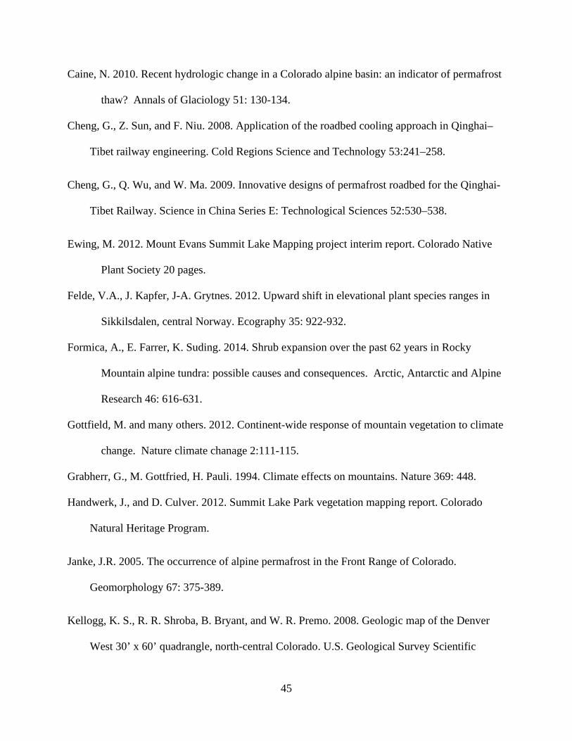
45
Caine, N. 2010. Recent hydrologic change in a Colorado alpine basin: an indicator of permafrost
thaw? Annals of Glaciology 51: 130-134.
Cheng, G., Z. Sun, and F. Niu. 2008. Application of the roadbed cooling approach in Qinghai–
Tibet railway engineering. Cold Regions Science and Technology 53:241–258.
Cheng, G., Q. Wu, and W. Ma. 2009. Innovative designs of permafrost roadbed for the Qinghai-
Tibet Railway. Science in China Series E: Technological Sciences 52:530–538.
Ewing, M. 2012. Mount Evans Summit Lake Mapping project interim report. Colorado Native
Plant Society 20 pages.
Felde, V.A., J. Kapfer, J-A. Grytnes. 2012. Upward shift in elevational plant species ranges in
Sikkilsdalen, central Norway. Ecography 35: 922-932.
Formica, A., E. Farrer, K. Suding. 2014. Shrub expansion over the past 62 years in Rocky
Mountain alpine tundra: possible causes and consequences. Arctic, Antarctic and Alpine
Research 46: 616-631.
Gottfield, M. and many others. 2012. Continent-wide response of mountain vegetation to climate
change. Nature climate chanage 2:111-115.
Grabherr, G., M. Gottfried, H. Pauli. 1994. Climate effects on mountains. Nature 369: 448.
Handwerk, J., and D. Culver. 2012. Summit Lake Park vegetation mapping report. Colorado
Natural Heritage Program.
Janke, J.R. 2005. The occurrence of alpine permafrost in the Front Range of Colorado.
Geomorphology 67: 375-389.
Kellogg, K. S., R. R. Shroba, B. Bryant, and W. R. Premo. 2008. Geologic map of the Denver
West 30’ x 60’ quadrangle, north-central Colorado. U.S. Geological Survey Scientific

46
Investigations Map 3000.
Komarkova, V. 1979. Alpine vegetation of the Indian Peaks Area, Front Range, Colorado Rocky
Mountains. Flora et vegetation Mundi, J. Cramer. FL-9490 Vaduz. 591 pages.
Korner, C. 1995. Alpine plant diversity: a global survey and functional interpretations. Pp. 45-
62, in F.S. Chapin and C. Korner, Eds. Arctic and alpine biodiversity: patterns, causes
and ecosystem consequences. Springer, Berlin, Germany.
Laudeman, S. (2009). Geotechnical Report: SH 5 Summit Lake Pavement Distress. Technical
Report 10 p. Denver, CO: Colorado Department of Transportation Materials and
Geotechnical Branch.
Leibundgut, C., P. Maloszewski, and C. Kulls. 2009. Tracers in Hydrology. John Wiley and
Sons.
Liljedahl, A. K., J. Boike, and many others. Pan-arctic ice-wedge degradation in warming
permafrost and its influence on tundra hydrology. Nature Geoscience 9: 312-318.
Linhart, Y. and J. Gehring. 2003. Genetic variability and its ecological implications in the clonal
plant Carex scopulorum Holm in Colorado tundra. Arctic, Antarctic and Alpine
Research 35: 429-433.
Madole, R. F., D. P. VanSistine, and J. A. Michael. 1998. Pleistocene glaciation in the upper
Platte River drainage basin, Colorado.
Malanson, G., L Bengtson, D. Fagre. 2012. Geomorphic determinants of species composition in
alpine tundra, Glacier National park, USA. Arctic, Antarctic and Alpine Research
44:197-209.
Mull, D. S., T. D. Lieberman, J. L. Smoot, and L. H. Woosley. 1988. Application of Dye-Tracing
Techniques for Determining Solute-Transport Characteristics of Ground Water in Karst

47
Terranes:115.
Marr, J. W. 1967. Ecosystems of the east slope of the Front Range in Colorado. University of
Colorado Studies, Series in Biology No. 8., University of Colorado Press, Boulder, CO.
134p.
McClymont, A., J. Roy, M Hayashi, L Bentley, H. Maurer and G. Langston. 2011.
Investigatingground water flow paths within pro-glacial moraine using multiple
geophysical methods. J. Hydrology 399: 57-69.
Pewe, T.L. 1983. Alpine permafrost in the contiguous United States: a review. Arctic and
Alpine Research 15: 145-156.
Rogger, M., G.B. Chirico, H. Hausmann, K. Krainer, E. Brückl, P. Stadler, G. Blöschl. 2017.
Impact of mountain permafrost on flow path and runoff response in a high alpine
catchment. Water Resources Research 10.1002/2016WR019341.
Scharnagl, K., D. Johnson, D. Ebert-May. 2019. Shrub expansion and alpine plant community
change: 40-year record from Niwot Ridge, Colorado. Plant Ecology and Diversity.
https://doi.org/10.10080.17550874.2019.1641757.
Smart, C., and B. Simpson. 2002. Detection of fluorescent compounds in the environment using
granular activated charcoal detectors. Environmental Geology 42:538–545.
Smart, P. L., and I. M. S. Laidlaw. 1977. An evaluation of some fluorescent dyes for water
tracing. Water Resources Research 13:15–33.
Spasojevic, M., W. Bowman, H. Humphries, T. Seastedt, K. Suding. 2013. Changes in alpine
vegetation over 21 years: are patterns across a heterogenous landscape consistent with
predictions? Ecosphere 49: article 17.
Utsi, E.C. (2017). Ground Penetrating Radar: Theory and Practice, Cambridge, MA: Elsevier.

48
Walker, M., D. Walker, T. Theodose, P.J. Webber. 2001. The vegetation: hierarchical species-
environment relationships. Pp. 99-127, in WD Bowman and T. Seastedt, eds. Structure
and function of an alpine ecosystem. Oxford University Press, Oxford, UK.
Weber, W. A. 2008. The alpine flora of Summit Lake, Mount Evans, Colorado. University of
Colorado Museum.
Weber, W.A. 2003. The middle-Asian element in the southern Rocky Mountain flora of the
western United States: a critical biogeographical review. 30: 649-685.
Weber, W.A. 1991. The alpine flora of Summit Lake, Mount Evans, Colorado. Aquilegia 15:3-7.
Williams-Mounsey, J., R. Grayson, A. Crowle, J. Holden. 2021. A review of the effects of
vehicular access roads on peatland ecohydrological processes. Earth-Science Reviews
214: 103528.

49
Appendix 1. Plant species and ground cover frequency in 237 study plots.
Species Name Species ID Growth Form
Plots Frequency
Acomastylis rossii (R. Br.) Greene ssp. turbinata (Rydberg) W.A.Weber
ACOROS Herbaceous 94 0.397
Alopecurus magellanicus Lam. ALOMAG Graminoid 11 0.046 Artemisia scopulorum A. Gray ARTSCO Herbaceous 67 0.283 Aulacomnium palustre (Hedw.) Schwägr. AULPAL Bryophyte 13 0.055 Bistorta bistortoides (Pursh) Small BISBIS Herbaceous 126 0.532 Bistorta vivipara (L.) Delarbre BISVIP Herbaceous 119 0.502 Bouteloua simplex Lag. BOUSIM Graminoid 6 0.025 Brachythecium cirrosum (Schwägr.) Schimp. BRACIR Bryophyte 6 0.025 Campylium protensum (Brid.) Kindb. CAMPRO Bryophyte 2 0.008 Campylopus schimperi Milde CAMSCH Bryophyte 1 0.004 Cephaloziella divaricata (Sm.) Schiffn. CAPDIV Bryophyte 2 0.008 Carex capillaris L. CARCAP Graminoid 1 0.004 Carex ebenea Rydb. CAREBE Graminoid 21 0.089 Carex elynoides T. Holm CARELY Graminoid 4 0.017 Carex saxatilis L. CARSAX Graminoid 8 0.034 Carex scopulorum T. Holm CARSCO Graminoid 165 0.696 Castilleja occidentalis Torr. CASOCC Herbaceous 21 0.089 Cerastium beeringianum Cham. & Schltdl. CERBEE Herbaceous 18 0.076 Ceratodon purpureus (Hedw.) Brid. CERPUR Bryophyte 2 0.008 Cladonia spp. CLASPP Bryophyte 1 0.004 Codriophorus fascicularis (Hedw.) Bedn.-Ochyra & Ochyra
CODFAS Bryophyte 1 0.004
Deschampsia brevifolia R.Br. DESCES Graminoid 121 0.511 Didymodon asperifolius (Mitt.) H.A. Crum, Steere & L.E. Anderson
DIDASP Bryophyte 2 0.008
Entodon concinnus (De Not.) Paris ENTCON Bryophyte 2 0.008 Erigeron grandiflorus Hook. ERIGRA Herbaceous 2 0.008 Festuca brachyphylla Schult. & Schult. f. FESBRA Graminoid 20 0.084 Festuca minutiflora Rydb. FESMIN Graminoid 19 0.080 Gentiana algida Pall. GENALG Herbaceous 37 0.156 Juncus triglumis var. albescens Lange JUNALB Graminoid 3 0.013 Juncus biglumis L. JUNBIG Graminoid 2 0.008 Juncus castaneus Sm. JUNCAS Graminoid 5 0.021 Juncus triglumis L. JUNTRI Graminoid 11 0.046 Kobresia myosuroides (Vill.) Fiori KOBMYO Graminoid 41 0.173 Kobresia sibirica (Turcz. ex Ledeb.) Boeckeler
KOBSIB Graminoid 6 0.025
Kobresia simpliciuscula (Wahlenb.) Mack. KOBSIM Graminoid 1 0.004 Koenigia islandica L. KOEISL Herbaceous 1 0.004 Lloydia serotina (L.) Salisb. ex Rchb. LLOSER Herbaceous 6 0.025

50
Species Name Species ID Growth Form
Plots Frequency
Luzula spicata (L.) DC. LUZSPI Graminoid 34 0.143 Micranthes rhomboidea (Greene) Small MICRHO Herbaceous 9 0.038 Minuartia obtusiloba (Rydb.) House MINOPT Herbaceous 7 0.030 Oncophorus wahlenbergii Brid. ONCWAH Bryophyte 1 0.004 Paraleucobryum enerve (Thed.) Loeske PARENE Bryophyte 1 0.004 Pedicularis groenlandica Retz. PEDGRO Herbaceous 15 0.063 Plagiomnium ellipticum (Brid.) T.J. Kop. PLAELL Bryophyte 1 0.004 Poa alpina L. POAALP Graminoid 29 0.122 Pogonatum urnigerum (Hedw.) P. Beauv. POGURN Bryophyte 10 0.042 Pohlia cruda (Hedw.) Lindb. POHCRU Bryophyte 3 0.013 Polytrichum juniperinum Hedw. POLJUN Bryophyte 1 0.004 Pseudocalliergon angustifolium Hedenäs PSEANG Bryophyte 1 0.004 Psychrophila leptosepala (DC) W.A.Weber CALLEP Herbaceous 136 0.574 Ptychostomum pseudotriquetrum (Hedw.) J.R. Spence & H.P. Ramsay ex Holyoak & N. Pedersen
PTYPSE Bryophyte 2 0.008
Ranunculus eschscholtzii Schltdl. RANESC Herbaceous 2 0.008 Rhodiola integrifolia Raf. RHOINT Herbaceous 62 0.262 Rhodiola rhodantha (A. Gray) H. Jacobsen RHORHO Herbaceous 36 0.152 Rhytidium rugosum (Hedw.) Kindb. RHYRUB Bryophyte 8 0.034 Salix arctica Pall. SALARC Woody 11 0.046 Salix brachycarpa Nutt. SALBRA Woody 7 0.030 Salix nivalis Hook. SALNIV Woody 1 0.004 Salix planifolia Pursh SALPLA Woody 13 0.055 Sanionia uncinata (Hedw.) Loeske SANUNC Bryophyte 9 0.038 Sarmentypnum exannulatum (Schimp.) Hedenäs
SAREXA Bryophyte 27 0.114
Sarmentypnum sarmentosum (Wahlenb.) Tuom. & T.J. Kop.
SARSAR Bryophyte 36 0.152
Saxifraga serpyllifolia Pursh SAXSER Herbaceous 9 0.038 Saxifraga serpyllifolia Pursh SAXSER Herbaceous 6 0.025 Schistidium boreale Poelt SCHBOR Bryophyte 2 0.008 Scorpidium cossonii (Schimp.) Hedenäs SCOCOS Bryophyte 2 0.008 Silene acaulis (L.) Jacq. SILACA Herbaceous 7 0.030 Stellaria umbellata Turcz. ex Kar. & Kir. STEUMB Herbaceous 5 0.021 Thalictrum alpinum L. THAALP Herbaceous 19 0.080 Trifolium parryi A. Gray TRIPAR Herbaceous 116 0.489 Trisetum spicatum (L.) K. Richt. TRISPI Graminoid 21 0.089 Unidentified freshwater algae ALGAE Algal mat 4 0.017 BARE Bare soil 177 0.747 LITTER Litter 213 0.899 DEDCAR Dead Carex 28 0.118

51
Appendix 2. Ground-Penetrating Radar surveys of the Mt. Evans Highway
Randall Bonnell and Dr. Daniel McGrath
Department of Geosciences, Colorado State University
R. Bonnell conducting 100 MHz common offset ground-penetrating radar surveys near Summit Lake, Mt. Evans.

52
Fieldwork Overview:
On August 20-21, 2020, we collected 2770 m of common offset ground-penetrating radar
(GPR) surveys along the Mt Evans Highway and surrounding tundra near Summit Lake using a
Sensors and Software ProEx control unit. We used the more mobile (sled-mounted) 250 MHz
antennas to collect 2500 m throughout the study area and the deeper penetrating 100 MHz
antennas to collect five transects perpendicular to the road and its shoulders, totaling 270 m. To
obtain velocity measurements, we collected two common mid-point (CMP) surveys, one with the
250 MHz north of the road and the other with the 100 MHz on the road.
Summary of Findings:
Velocity Analysis: We analyzed the two CMP surveys and identified a two-layer system
above the surface of the permafrost. However, given the lower penetration depth of the 250 MHz
survey and the likely complex layer geometry beneath that specific survey site, we only present
the 100 MHz results here. We presume the upper layer is dry till/soil and the lower layer, below
the water table, is wet/saturated till/soil. We modelled the radar velocities using a semblance
analysis and estimate the velocities of the upper and lower layers as 0.10254 m ns-1 and 0.07938
m ns-1, respectively. These velocity estimates agree well with published values (Utsi, 2017),
where dry soil velocity is estimated at 0.1 m ns-1 and wet inorganic soil velocity is estimated at
0.055-0.077 m ns-1.
100 MHz Analysis: In the 100 MHz survey lines, we found that the active layer thickness
increased substantially beneath the Mt. Evans road (Figure 1). The thickness of the active layer
increased from 1.5-2.5 m on the road shoulders to 3-4.5 m beneath the center of the road. Beneath
the road, the active layer was thickest along Transect E (easternmost, intersects Borehole 1) and

53
thinnest along Transects A- B (westernmost, Transect B intersects Borehole 3), suggesting a
possible relationship between active layer thickness and the age/duration of the road-related
disturbance. Future GPR surveys with the 100 MHz system could help better constrain this
relationship.
250 MHz Analysis: We collected ~2500 m of common-offset 250 MHz (higher frequency,
shorter wavelength) surveys, but only found ~1400 m to be interpretable. In particular, the 250
MHz radargrams do not consistently show coherent layering beneath the road surface nor along
the north section of Transect A. Outside of these regions, the subsurface layering was more
coherent, and thus we identified a reflector that we interpreted as the base of the active layer. To
assess the accuracy of our picks, we analyzed crossover points. In the spiral south of the road, we
compared six locations with coincident data and found a mean disagreement of 0.05 m and a
maximum disagreement of 0.14 m. In the spiral north of the road, an analysis of two crossover
points differed in active layer thickness by 0.60 m and 1.30 m, indicative of poorer agreement in
this portion of the study area. We also compared active layer thicknesses measured by the 250
MHz and 100 MHz antennas near Transect D, yielding a mean difference of 0.11 m ± 0.09 m SD
from eleven spatially coincident points. The differences are likely attributable to the fact that the
250 MHz antenna was not as well coupled to the ground surface (given that it was dragged across
the surface rather than placed at each survey point) and that the shorter wavelengths at this
frequency resulted in greater variability in the reflection depth.
Water Table Results: We interpret a continuous reflector above the active layer reflector as
the water table. However, these depths exhibit greater spatial heterogeneity than expected (Figure
2), and we suggest that they should be evaluated against any available well data.

54
Active Layer Results: We combined picks from the 100 MHz cross-sections and the 250
MHz transects to highlight the spatial distribution of the active layer thickness across the study
area (Figure 3).
Figure 1: Depth to permafrost surface picked from 100 MHz lines. Transects were surveyed perpendicular to the road. Approximate road boundaries are shown.
Future Directions:
1. We found the 100 MHz radargrams to be easier to interpret and more consistent in
detecting the permafrost surface. Although data collection is more tedious and time-consuming,
we recommend that future surveys primarily rely on this frequency.
2. Compare GPR-derived water table depths to well data.

55
Figure 2: Water table and depth to permafrost surface in the spiral to the north of the road (a.) and the spiral to the south of the road (b.). Depths derived from 250 MHz GPR survey.
Figure 3: Map of active layer thicknesses from combined 100 and 250 MHz GPR picks. Transects A-E and the locations of Boreholes 1-3 are labeled.

56
100 MHz Processing Flow: (1) Time-zero Correction, (2) De-wow, (3) Energy Decay
gain, (4) Picked two-way travel time (TWT) for active layer depth, (5) Picked TWT for top of
water table.
250 MHz Processing Flow: (1) Time-zero Correction, (2) De-wow, (3) Equidistant Trace
Interpolation, (4) Energy Decay gain, (5) Butterworth Band Pass Filter, (6) Running Average, (7)
Picked TWT for active layer depth, (8) Picked TWT for top of water table.
This processing flow produces a radargram with discernible layers, as illustrated by the
100 MHz examples below (Figures 4-5). The prominent lower reflector is interpreted as the base
of the active layer and a prominent reflector above it is interpreted as the top of the water table.
Reflections from bedrock may exist but are difficult to follow along-profile.
We used the velocities obtained from the CMP semblance models to convert the measured
two-way travel times to depth of the active layer. We did not consider the pavement as a layer in
this analysis. From the borehole analysis conducted in 2009 (Geotechnical Report: SH5 Summit
Lake Pavement Distress, 2009), Boreholes 2-6 have 0.15 m of pavement and Borehole 1 has 1.4
m of pavement. We expect the impact of this layer to be minimal for Transects A-D, but
potentially significant at Transect E, which contains Borehole 1. However, given the uncertainty
of the exact material (and thus radar velocity), we have not included this in the analysis presented
here.

57
Figure 4: 100 MHz radargram collected along Transect E and coinciding with Borehole 1. Left is to the north; right is to the south. Colored lines denote picked water table (blue) and active layer (red) depths. In this location, several point reflectors (exhibited as hyperbolas) appear in the channel feature. Transect E is the highest elevation transect and is furthest to the east.
Figure 5: 100 MHz radargram collected along Transect B and coinciding with Borehole 3. Right is to the north; left is to the south. Here, the channel feature appears to be less dramatic. Borehole 3 is west and lower in elevation than Borehole 1.
References:
Laudeman, S. (2009). Geotechnical Report: SH 5 Summit Lake Pavement Distress. Technical
Report 10 p. Denver, CO: Colorado Department of Transportation Materials and
Geotechnical Branch.
Utsi, E.C. (2017). Ground Penetrating Radar: Theory and Practice, Cambridge, MA: Elsevier.

58
Appendix 3. Techniques to Minimize Roadway Damage from Permafrost Degradation and
Freeze-Thaw in Mountain Environments of Colorado
Jeremy R. Shaw July 2021
A3.1 Introduction
Ongoing global climate changes have accelerated permafrost degradation around the
world, leading to significant roadway damage and loss of functionality (Cheng et al. 2008, 2009,
Doré et al. 2016, Trofimenko et al. 2017). Conventional approaches developed during the mid-
20th century are no longer adequate for preventing permafrost degradation and associated
embankment failure (Cheng et al. 2008, 2009, Doré et al. 2016). Increasing thaw rates modify
the geotechnical and hydrological impacts to road embankments and will shorten the effective
lifespan of existing infrastructure, requiring new design specifications to ensure resilient and
sustainable operation (Auld et al. 2006, Fortier and Stephani 2010, Kuznetsova et al. 2016, Mu et
al. 2018a). These challenges have resulted in a rapidly growing body of research on roadway
design techniques to minimize permafrost thaw and embankment settling, and only recently have
long-term performance data from test sites become available.
Frost damage to roadways is a common problem in Colorado (Ardani 1989), and
permafrost degradation is expected to enhance the extent and severity in high-elevation sites
(Benedict 1976, French 2007). Rising air temperatures will likely increase the frequency of
freeze-thaw cycles in previously frozen ground during winter, causing greater pavement distress
and reducing service life (Mills et al. 2009, Zubeck et al. 2012, Bilodeau et al. 2015). While the
fundamentals of frost damage mitigation have not changed, many new techniques and
improvements have been made in recent years.

59
This report reviews and synthesizes available information on design techniques to
minimize permafrost degradation and damage to roadways from thaw-induced deformation and
freeze-thaw action, with an emphasis on recent developments. More than 258 technical
documents, journal articles, book chapters, and conference proceedings were reviewed.
Information drawn from reports and experiments on roadways, railways, and runways. Since the
specific performance of techniques is strongly dependent on local conditions and design
specifications, discussion was limited to general principles and findings. Considerations to
minimize hydrologic alterations to wetlands were also included.
A3.2 Alpine Permafrost
Permafrost occurs in about 25% of Earth’s land surface, where mean annual ground
temperature (MAGT) is below 0˚C for 2+ consecutive years, regardless of ice content (Pewe
1983, French 2007, Dobinski 2011). Discontinuous or sporadic permafrost is generally found
where mean annual air temperature (MAAT) is below -1˚C, while continuous permafrost is
widespread where MAAT is less than -8˚C. Outside of polar regions, alpine or mountain
permafrost is common at the higher elevations of large mountain ranges in the northern
hemisphere (Gorbunov 1978, Pewe 1983, French 2007). The elevation above which alpine
permafrost occurs depends on latitude, slope aspect, and regional climate. The spatial extent,
depth, and thickness are controlled by local topographic characteristics affecting snow cover, soil
moisture and water table depth, and cold air drainage, as well as soil and vegetation properties
(Pewe 1983, Harris 1986, French 2007, Dobinski 2011, Walvoord and Kurylyk 2016).
Within Colorado, alpine permafrost occurs above roughly 3,500 m, while sporadic
permafrost may be encountered down to 2,000 m (Gorbunov 1978, Harris 1986). Alpine
permafrost is likely to be dry in poorly developed coarse soils and on steep slopes. Ice-rich

60
permafrost is more prevalent in wetland areas along valley bottoms, fine-grained glacial deposits,
and flatter unglaciated peneplains. Ice-rich permafrost has been documented on Mount Evans
and Pikes Peak, where it has affected building foundations (Ives and Fahey 1971). Observations
from numerous shallow (<2 m) boreholes and severe roadway subsidence cofirm the presence of
ice-rich permafrost beneath SH5 within the Summit Lake Park wetland complex.
Areas of alpine permafrost are likely contracting due to disequilibrium with current
climatic conditions (Pewe 1983), and this decline will continue with ongoing global climate
changes (French 2007). Observed rates of recent warming and permafrost degradation increase
with elevation and latitude, mainly from reduced snow cover and more efficient heat transfer
from the atmosphere (Pepin et al. 2015, Yu et al. 2015a). Permafrost degradation begins with
increasing seasonal thaw depths that eventually form progressively larger vertical taliks
(depressions or voids in permafrost), and continued melting thins the permafrost layer from both
above and below (Yu et al. 2013, Walvoord and Kurylyk 2016). Model results suggest that
alpine permafrost coverage in the northern Front Range of Colorado will decrease by 94% with
MAAT increases of 2˚C, and will be essentially eliminated at increases of 4˚C (Janke 2005).
Where permafrost persists, higher air temperatures will increase summer thaw depths (Harris
2005, French 2007).
A3.3 Impacts of Roadways on Permafrost
It has long been known that conventional road design and construction practices increase
permafrost thaw depths by altering the thermal regime below embankments (Johnson 1952,
Department of the Army 1954). The replacement of organic soils and vegetation with low-albedo
roadway materials increases heat gain from solar radiation, allowing these more conductive
surfaces to transfer larger heat loads into the ground. In addition to local air temperature, thermal

61
regimes below embankments are driven mainly by insolation and thermal conductivity of surface
materials (Darrow 2011, Yu et al. 2015a, Qian et al. 2016). Insolation on flat embankment
surfaces increases linearly with net solar radiation, while aspect and slope angle constrain
insolation on embankment slopes (Chou et al. 2012). This causes total heat gain and thaw depth
to increase with embankment top width, while asymmetrical heating and thawing occur under
embankment slopes with greater insolation, referred to as the “sunny-shady effect” (Cheng et al.
2009, Chou et al. 2010, Yu et al. 2015b, Chang et al. 2017). Over decadal time scales, increased
thaw depths and talik development beneath roadways enhance local permafrost degradation
(French 2007, Yu et al. 2013, Grandmont et al. 2015, Walvoord and Kurylyk 2016), which can
ultimately form a continuous thaw ribbon beneath the roadway (Department of the Army 1954).
Roadway embankments also alter the locations and amounts of water and snow
accumulation, which further contribute to permafrost thaw. Shallow groundwater flow beneath
embankments can increase MAGT and thaw depths on the upgradient side as heat is advected
from water to the embankment materials (Fortier and Stephani 2010, de Grandpré et al. 2012,
Zottola et al. 2012, Zhongqiong et al. 2018). Deep thaw ribbons or taliks beneath embankments
intercept and store groundwater, creating a feedback loop that increases thaw depth. Significant
heat transfer and melting also occur where water ponds against embankment toes and in roadside
ditches (Guo et al. 2016, Mu et al. 2018a), as well as from water flowing through culvert
crossings (Périer et al. n.d.). Snow accumulation against the side slopes insulates the ground and
decreases heat loss during winter (Lanouette et al. 2015), resulting in greater thaw depths along
the embankment toes (O’Neill and Burn 2017).

62
A3.4 Impacts of Permafrost Degradation on Roadway Stability
Accelerated thawing of ice-rich permafrost poses significant geotechnical hazards to
roads and other infrastructure (Harris 2005, Kääb et al. 2005, French 2007). Thawing reduces the
compressive strength and bearing capacity of frozen soils and jointed bedrock, while increased
pore water pressures from melt water can reduce slope stability. This often produces subsidence
and slope instability in unconsolidated sediments and soft lithologies (e.g., shale), while
rockslides and debris flows become more common in competent lithologies (Harris 2005).
Although the processes and rates vary in time and space, four primary mechanisms of thaw-
induced surface deformation in unconsolidated sediments have been documented: seasonal frost-
heave on wet ground; slow and steady settlement (<2 cm/year) on dry permafrost; rapid episodic
subsidence from consolidation of ice-rich layers; and rapid and steady settlement from lateral
creep of warm permafrost in coarse soils (Yu et al. 2016a). Frost-heave is a near-surface process,
while thaw consolidation and creep tend to occur at greater depths. Settlement is generally
greatest on rapidly thawing ice-rich permafrost, while slower warming promotes creep (Yu et al.
2013).
The most common mode of embankment deformation is rapid settlement beneath the side
slopes and toes, causing shoulder rotation and longitudinal cracking along the centerline (Clark
and Simoni 1976, Goering 1998, Beaulac and Dore 2006, Fortier et al. 2011, Zubeck et al. 2012,
Doré et al. 2016). Transverse settlement due to asymmetrical heating on the sunny side is a
widespread problem in high elevation regions such as the Qinghai-Tibet Plateau (Chou et al.
2010). For roads built on-grade or low embankments, longitudinal subsidence beneath the road
centerline can create a concave road cross section (Jin et al. 2012a). Much of SH-5 through

63
portions of the Summit Lake Park wetland complex exhibit this pattern. Extreme localized
deformation also occurs through boulder jacking from the subgrade.
Preventing excessive embankment settling and deformation requires designs that account
for likely hydrological changes from climate-induced permafrost degradation (Fortier and
Stephani 2010, de Grandpré et al. 2012, Zottola et al. 2012, Doré et al. 2016, Mu et al. 2018a,
Zhongqiong et al. 2018). The active layer (depth of seasonal thaw) often functions as a seasonal
perched aquifer, and increased groundwater fluxes from upgradient melt water modify local
hydrogeology (Walvoord and Kurylyk 2016). The subsequent development and enlargement of
groundwater discharge zones and thaw lakes significantly increase heat transfer into the ground,
creating and enlarging taliks that further accelerate permafrost degradation beyond the increasing
seasonal thaw depth. This feedback loop can alter the locations and magnitudes of surface and
subsurface water fluxes (Walvoord and Kurylyk 2016). Such hydrological changes can further
exacerbate thaw-induced embankment subsidence and deformation (Fortier and Stephani 2010,
Doré et al. 2016, Mu et al. 2018a). Accelerated thaw and subsidence are likely to occur where
shallow groundwater flows beneath embankments (Fortier and Stephani 2010, de Grandpré et al.
2012, Zottola et al. 2012, Zhongqiong et al. 2018), where surface water is impounded against
embankment toes and in roadside ditches (Guo et al. 2016, Mu et al. 2018a), and potentially at
culvert crossings (Périer et al. n.d.). For example, water ponded against the embankment toe of
the Qinghai-Tibet Railway produced a 5.5 m deep thaw bubble, resulting in 16 cm of settlement
(Mu et al. 2018a). While retrofitting with passive cooling devices failed to refreeze the subgrade,
draining the ponds did result in permafrost recovery within two winters. Most thermal
conduction models used in site design do not account for advection from shallow groundwater
(Zottola et al. 2012, Darrow et al. 2013), although Darrow et al. (2013) includes both processes.

64
A3.5 Strategies to Protect Permafrost and Transportation Infrastructure
Three strategies are used to mitigate permafrost degradation beneath transportation
infrastructure and minimize damage from settlement (Doré et al. 2016): minimize heat inputs to
underlying permafrost; maximize heat extraction; and reinforce embankments to resist
deformation.
A3.5.1 Techniques to Minimize Heat Inputs
Since the primary heat source to permafrost underlying roadways is solar radiation
absorbed by embankment surface materials with low albedos and high thermal conductivities,
minimizing heat gain through these surfaces can help to reduce thaw depths (Doré et al. 2016).
Subgrade insulation, pavements that reflect or redirect solar radiation, sun/snow sheds and dry
bridges are effective techniques to reduce heat loads from the atmosphere. Advected heat from
shallow groundwater and surface water can be locally significant, particularly in wetlands, so
insulated culvert crossings, modified embankment geometry, and porous embankments can be
used to mitigate heat loads. Techniques to minimize heat gain are useful in slowing thaw rates,
but by themselves are not capable of stopping or reversing permafrost degradation, so they are
typically used in combination with heat extraction techniques (Cheng et al. 2008, 2009, Doré et
al. 2016).
A3.5.1.1 Subgrade Insulation
Subgrade insulation, combined with increased embankment height, is a conventional
approach to limit heat inputs to underlying permafrost (Johnson 1952, Department of the Army
1954). This technique is used to reduce heat input during the summer, but also reduces heat loss
during the winter (Doré et al. 2016). Many high-elevation roads on the Qinghai-Tibet Plateau
were built with subgrade insulation in tall embankments, but this did not stop thaw settlement

65
(Cheng et al. 2008, 2009). However, subgrade insulation may be more effective in low-elevation
sites with less insolation (Esch 1994). At best, insulation can slow thaw rates, and must be
installed on cold ground during winter or spring (Doré et al. 2016). Extruded polystyrene is
typically used, since other synthetic insulations absorb water and have lower compressive
strength (Gandahl 1988, Esch 1994). Cheng et al. (2004) review the use of subgrade insulation
for permafrost protection and provide recommended embankment heights depending on MAAT
and road surface material. Where available, natural aggregate and fill materials with lower
thermal conductivities could be used to improve insulative capacity (Côté and Konrad 2005).
Polystyrene insulation around culverts can help to reduce heat advection from water (Périer et al.
n.d.). Insulation is commonly used to complement other techniques.
A3.5.1.2 Reflective and Insulative Pavement
A variety of pavement types and surface treatments can help to reduce heat accumulation
or heat transfer to underlying embankment materials. These include high albedo pavement
surfaces that reflect solar radiation, low thermal conductivity pavements that reduce heat transfer
to the subgrade, and oriented heat conducting pavements that transfer heat away from the
subgrade. High albedo surface treatments have received the greatest attention, but none of these
approaches are widely used.
High albedo pavement surfaces reduce heat accumulation in embankment materials by
reflecting incoming shortwave radiation. Many reflective surface treatments have been tested,
but their use has been limited due to low durability and loss of traction (Doré et al. 2016)
although fine aggregate can be incorporated to improve skid resistance (Iwama et al. 2012).
Several experiments in Alaska have shown that reflective pavements can lower ground
temperatures and slow thaw settlement (Reckard 1985). Significant solar gain occurs through
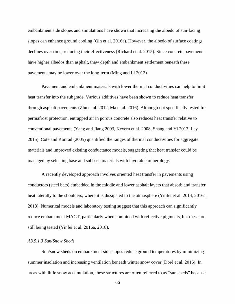
66
embankment side slopes and simulations have shown that increasing the albedo of sun-facing
slopes can enhance ground cooling (Qin et al. 2016a). However, the albedo of surface coatings
declines over time, reducing their effectiveness (Richard et al. 2015). Since concrete pavements
have higher albedos than asphalt, thaw depth and embankment settlement beneath these
pavements may be lower over the long-term (Ming and Li 2012).
Pavement and embankment materials with lower thermal conductivities can help to limit
heat transfer into the subgrade. Various additives have been shown to reduce heat transfer
through asphalt pavements (Zhu et al. 2012, Ma et al. 2016). Although not specifically tested for
permafrost protection, entrapped air in porous concrete also reduces heat transfer relative to
conventional pavements (Yang and Jiang 2003, Kevern et al. 2008, Shang and Yi 2013, Ley
2015). Côté and Konrad (2005) quantified the ranges of thermal conductivities for aggregate
materials and improved existing conductance models, suggesting that heat transfer could be
managed by selecting base and subbase materials with favorable minerology.
A recently developed approach involves oriented heat transfer in pavements using
conductors (steel bars) embedded in the middle and lower asphalt layers that absorb and transfer
heat laterally to the shoulders, where it is dissipated to the atmosphere (Yinfei et al. 2014, 2016a,
2018). Numerical models and laboratory testing suggest that this approach can significantly
reduce embankment MAGT, particularly when combined with reflective pigments, but these are
still being tested (Yinfei et al. 2016a, 2018).
A3.5.1.3 Sun/Snow Sheds
Sun/snow sheds on embankment side slopes reduce ground temperatures by minimizing
summer insolation and increasing ventilation beneath winter snow cover (Doré et al. 2016). In
areas with little snow accumulation, these structures are often referred to as “sun sheds” because

67
their primary function is shading. Where winter snow accumulation insulates the ground, they
are often referred to as “snow sheds” because they facilitate ventilation and heat loss. Thus, they
effectively lower ground temperatures beneath embankments in snowy overcast regions (Lepage
et al. 2012a) and in dry sunny regions (Cheng et al. 2008, 2009). Configurations range from tall
structures covering the entire embankment, to low (~1 m) platforms covering the side slopes.
They have been shown to reduce thaw depths by 2 to 7 m in China (Luo et al. 2018b), and by 5
m in Alaska (Zarling and Braley 1986). Trofimenko et al. (2017) reports that sun/snow sheds are
commonly used in Russia.
A3.5.1.4 Dry Bridges
Dry bridges, or pile-elevated roadways, shade the ground and prevent heat transfer from
roadways. They can also function as linear snow sheds, enhancing heat loss during winter. Dry
bridges have been used to successfully prevent accelerated thawing and settlement on sections of
the Qinghai-Tibet Railway (Cheng et al. 2009). They are also commonly used along problematic
road sections in Russia, sometimes incorporating thermosiphons within the screw piles to
stabilize rapidly degrading permafrost (Trofimenko et al. 2017). Liu et al. (2018a) reviewed pile
performance and practice in cold regions. This approach requires minimal ground disturbance
and is an effective solution in areas with ice-rich permafrost and severe freeze-thaw.
A3.5.2 Techniques to Maximize Heat Extraction
Heat extraction methods remove heat from embankments and subgrade during winter,
and are consistently effective at mitigating thaw if designed to account for changing climate and
permafrost conditions during the service life (Doré et al. 2016). These techniques include air
convection embankments (and their many variations), heat drains, ventilation ducts,
thermosiphons, and modified embankment geometry. Passive cooling techniques often yield the

68
best results when used in combination (e.g., ACE with ventilation ducts) and with techniques to
reduce heat inputs. Snow removal is an active heat extraction method that may be useful where
other options are not available.
A3.5.2.1 Air Convection Embankments
Air convection embankments (ACE) are passive convective cooling structures built of
coarse poorly graded open aggregate to provide high porosity (~40%) and permit free air
circulation (Goering and Kumar 1996, Goering 1998, 2003, Xu and Goering 2008). During
winter, air temperature and density gradients between the cooler ambient air and the warmer air
within the embankment cause convective circulation through the pores that accelerates heat
extraction. During the summer, warmer outside air causes stratification that prevents circulation
within the pore network, and heat transfer occurs primarily through conduction. However, heat
conduction through the ACE is less than conventional embankment materials due to the
extremely high porosity (Goering and Kumar 1996, Goering 1998, 2003, Xu and Goering 2008).
A range of ACE configurations have been employed including: full embankments (conventional
ACE); crushed rock interlayer embankments or crushed rock embankments (CRE) that typically
comprise the bottom ~1.5 m of taller embankments; crushed rock interlayers with riser chimneys
or rock-filled trenches along the centerline; crushed rock revetments (CRR) that cover the side
slopes; and U-shaped ACEs that combine CREs and CRRs (Cheng et al. 2009). Geotextile fabric
below the base or subbase course prevents pores from filling with fines. Because the albedo of
crushed rock increases with mean particle diameter for sizes larger than 5 cm, structures built
with larger aggregate will experience lower heat loading from absorbed shortwave radiation
(Zhang et al. 2019). Smaller aggregate sizes increase effective albedo, and should be avoided
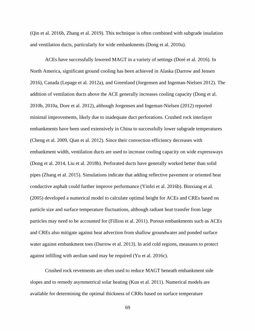
69
(Qin et al. 2016b, Zhang et al. 2019). This technique is often combined with subgrade insulation
and ventilation ducts, particularly for wide embankments (Dong et al. 2010a).
ACEs have successfully lowered MAGT in a variety of settings (Doré et al. 2016). In
North America, significant ground cooling has been achieved in Alaska (Darrow and Jensen
2016), Canada (Lepage et al. 2012a), and Greenland (Jorgensen and Ingeman-Nielsen 2012). The
addition of ventilation ducts above the ACE generally increases cooling capacity (Dong et al.
2010b, 2010a, Dore et al. 2012), although Jorgensen and Ingeman-Nielsen (2012) reported
minimal improvements, likely due to inadequate duct perforations. Crushed rock interlayer
embankments have been used extensively in China to successfully lower subgrade temperatures
(Cheng et al. 2009, Qian et al. 2012). Since their convection efficiency decreases with
embankment width, ventilation ducts are used to increase cooling capacity on wide expressways
(Dong et al. 2014, Liu et al. 2018b). Perforated ducts have generally worked better than solid
pipes (Zhang et al. 2015). Simulations indicate that adding reflective pavement or oriented heat
conductive asphalt could further improve performance (Yinfei et al. 2016b). Binxiang et al.
(2005) developed a numerical model to calculate optimal height for ACEs and CREs based on
particle size and surface temperature fluctuations, although radiant heat transfer from large
particles may need to be accounted for (Fillion et al. 2011). Porous embankments such as ACEs
and CREs also mitigate against heat advection from shallow groundwater and ponded surface
water against embankment toes (Darrow et al. 2013). In arid cold regions, measures to protect
against infilling with aeolian sand may be required (Yu et al. 2016c).
Crushed rock revetments are often used to reduce MAGT beneath embankment side
slopes and to remedy asymmetrical solar heating (Kun et al. 2011). Numerical models are
available for determining the optimal thickness of CRRs based on surface temperature

70
fluctuations (Sun et al. 2009). Doubling the CRR thickness on the sunny (south) side from 80 cm
to 160 cm produced uniform cooling below the embankment of the Qinghai-Tibet Railway in a
24-year simulation (Lai et al. 2004). Luo et al. (2018a) provided excellent documentation from
an 11-year field study validating the use of double-thickness CRRs on the south side of the
railway, which cooled the subgrade to natural ground temperatures and eliminated asymmetrical
heating. The permafrost table rose rapidly into the embankment shoulders during the first 5-6
years, significantly reducing settlement. Using hollow concrete bricks instead of crushed rock
may further increase convection and cooling efficiency (Jin et al. 2012b). Improved cooling has
also been reported when CRRs were covered with geotextile fabric and 20 cm of soil to prevent
summer heat gain (Liu et al. 2017), but this result was not obtained in field tests along the Alaska
Highway (Lepage et al. 2012a). Xu and Goering (2008) showed that CRRs effectively lowered
MAGT in near Fairbanks, Alaska, although Lepage et al. (2012a) found that the cooling
efficiency declined over three years along the Alaska Highway.
The performance of various ACE configurations has been compared along the Alaska
Highway in Canada, and the Qinghai-Tibet Railway in China. In Canada, a full ACE provided
the greatest MAGT reductions beneath the centerline over three years, followed by CRR (Lepage
et al. 2012a). Below the embankment shoulder, CRR extracted more heat while the full ACE and
CRR with soil cover produced net heat gains (Lepage et al. 2012a). In China, 14 years of data
showed no apparent differences in the ground temperatures below U-shaped ACEs and CRRs,
both of which lowered MAGT and raised the permafrost table (Mu et al. 2012, 2018b).
A3.5.2.2 Heat Drains
Heat drains are a relatively new technique to promote convective heat removal from
embankments, using a permeable geocomposite made of a corrugated plastic core enclosed

71
between geotextile fabric (Doré et al. 2016). This passive cooling structure functions similar to
an ACE but cold air is drawn in from risers on the embankment toe. Tested configurations
include a layer beneath the full embankment, or only under the side slope (Lepage et al. 2012a).
Heat drains under the full embankment are effective at lowering MAGT, and produce uniform
temperature fields (Dore et al. 2012, Lepage et al. 2012a).
A3.5.2.3 Ventilation Ducts
Ventilation ducts allow wind-driven convection of heat from the embankment, primarily
during the winter (Doré et al. 2016). Ducts are commonly made from solid or perforated pipes
buried within the embankment either perpendicular to the roadway, or longitudinally beneath the
toe slope. Open-ended pipes are susceptible to snow blockage, and riser vents are often used
instead. Performance may be improved if the ducts are closed during summer to prevent the
infiltration of warm air. This technique can be very effective at reducing MAGT and thaw depth,
but requires site-specific design and performs best when oriented into the prevailing wind
direction (Cheng et al. 2009, Doré et al. 2016). Appropriately designed ventilation ducts have
been shown to significantly reduce thaw depths (Dore et al. 2012, Tai et al. 2017), and
longitudinal ducts provided the greatest heat extraction from embankment slopes out of 12
methods tested along the Alaska Highway (Lepage et al. 2012a). Ventilation ducts have been
widely used to protect permafrost and prevent embankment settling along the Qinghai-Tibet
Railway, often in combination with other techniques (Cheng et al. 2008, 2009). Tests of duct
configurations along the railway showed that cooling capacity increased with pipe diameter (up
to 40 cm) and depth within the embankment, and were capable of reducing subgrade MAGT to
below 0˚C by the second year (Fujun et al. 2006). Additional passive heat extraction measures

72
such as ACE, CRR, and sun/snow sheds may be needed on the sunny sides of embankments to
prevent the development of asymmetrical temperature fields (Fujun et al. 2008, Qian et al. 2016).
A3.5.2.4 Thermosiphons
Thermosiphons for passive subgrade cooling have been reviewed by Yarmak and Long
(2002) and Wagner (2014). The most common type is a Two-Phase Closed Thermosiphon
(TPCT), consisting of sealed tubes containing a fluid of low boiling point (usually carbon
dioxide), the majority of which is in the gaseous phase. The conventional passive thermosiphon
has a sloping evaporator section buried within the embankment, connected by a riser to an
above-ground evaporator section which is usually fitted with fins to increase surface area and
heat exchange. When cooled below the condensation point by lower ambient temperatures
during winter, vapor condenses on the walls of the condenser and releases latent heat to the
atmosphere. The corresponding pressure reduction within the system causes the liquid phase in
the evaporator to vaporize, absorbing latent heat from the surrounding fill. Condensate within the
condenser flows back down to the evaporator via gravity. The cycle continues as long as the
condenser is cooler than the belowground evaporator, thus passively removing heat from the fill
until it reaches thermal equilibrium with the atmosphere. Therefore, passive thermosiphons
extract heat mainly during the freezing season, to rapidly cool embankments and refreeze them
for next thaw season. They are usually coupled with subgrade insulation to reduce incoming heat
load and limit thaw within the fill during summer, when the system is idle (Yarmak and Long
2002, Wagner 2014).
Other TPCT configurations have been developed but are less commonly used (Yarmak
and Long 2002, Wagner 2014). Where safety concerns do not favor aboveground structures,
buried condenser thermosiphons operate by releasing heat to near-surface embankment materials

73
instead of the atmosphere. Hairpin thermosiphons are a variation of buried TPCT with a bent
riser and condenser buried beneath the pavement, separated from the deeper evaporator by foam
insulation boards. Active TPCTs, where fluid circulation is controlled by a heat pump, allow for
other configurations such as flat loops and circuits within the fill material. Hybrid TPCTs
incorporate a heat pump to allow for both passive and active cooling, but these are typically only
used where rapid cooling is required or in retrofits where heat load was underestimated (Yarmak
and Long 2002, Wagner 2014).
Thermosiphons have been widely used to reduce ground temperatures, limit permafrost
degradation, and minimize settling beneath structures in Alaska, Canada, China, and Russia
(Wagner 2014). More recently, their application to roadway embankments have been
investigated at test sites in Alaska (Xu and Goering 2008, Wagner et al. 2010), and they have
been extensively deployed along highways and railways in the Qinghai-Tibet region of China
(Cheng et al. 2009, Zhang et al. 2011, Yu et al. 2016b). Three years of performance data for
three thermosiphon configurations tested near Fairbanks, Alaska showed that they all effectively
lowered ground temperatures and reduced seasonal thaw depth below embankment shoulders by
about 6 m (Wagner et al. 2010). Ten years of data from the Qinghai-Tibet Highway also
demonstrated significant reductions in embankment settlement rates (Yu et al. 2016b).
Thermosiphon efficiency and working time must be adjusted for local air temperature ranges and
insolation for maximum effectiveness, and numerical models have been developed to optimize
design (Zhi et al. 2005, Zhang et al. 2011, Pei et al. 2017, Yu et al. 2017). Field deployments
have also shown that they are most effective when combined with subgrade insulation (Zhi et al.
2005, Wagner et al. 2010, Zhang et al. 2011, 2016). An integrated approach to reducing thaw
rates below a four-lane highway consisted of L-shaped TPCTs to cool the embankment

74
centerline, CRRs to reduce solar heating on side slopes, and polystyrene subgrade insulation to
reduce heat loading (Zhang et al. 2016).
A3.5.2.5 Modified Embankment Geometry
Modifications to embankment geometry can increase heat extraction, as well as reduce
heat gain. Gentler side slopes (4H:1V to 6H:1V) reduce snow drift accumulation and drain water
further away from the toes (McGregor et al. 2008). Reduced snow cover on the side slopes
increases heat loss during the winter, helping to raise the permafrost table (Fortier et al. 2011,
O’Neill and Burn 2017), while reduced ponding against the toes reduces heat advection from
water (Fortier and Stephani 2010, Doré et al. 2016, Mu et al. 2018a). Embankment side slopes of
8H:1V significantly reduced thaw depths below an airstrip in Canada at construction costs
comparable to conventional embankments, and outperformed more expensive passive cooling
techniques (Dore et al. 2012). Since heat gain is a function of embankment top width, narrower
embankments can also reduce thaw depth (Cheng et al. 2009, Chou et al. 2010, Yu et al. 2015b,
Chang et al. 2017). Conventional techniques such as raising embankment height to increase
thermal resistance (Johnson 1952, Department of the Army 1954) are not effective under current
climatic conditions, particularly at high elevation sites (Cheng et al. 2009, Zhang et al. 2009).
A3.5.2.6 Snow Removal
Snow removal from embankment side slopes is an active heat extraction technique to
facilitate winter cooling (Doré et al. 2016, O’Neill and Burn 2017). Small-scale experiments
have shown that slowing accumulation rates and delaying the onset of deep snowpacks can help
to reduce MAGT and thaw depth (O’Neill and Burn 2017), and snow removal slightly increased
the cooling capacity of an ACE in Alaska (Darrow and Jensen 2016). However, test sections on
the Alaska Highway did not show significant effects over three years (Lepage et al. 2012a).

75
Nevertheless, snow removal is practiced in remote communities in northern Canada, where other
mitigation techniques are not available (McGregor et al. 2008). Since the thermal conductivity of
snow is a function of porosity, snow compaction is another potential strategy (O’Neill and Burn
2017). This technique is not currently feasible over large scales due to high cost and limited
effectiveness, but automation and scheduling based on real-time weather monitoring could yield
improvements.
A3.5.3 Techniques to Reinforce Embankments
Modified embankment geometry can be used to minimize deformation where permafrost
degradation cannot be avoided. Increased embankment height with subgrade insulation has been
the conventional approach to minimizing thaw settling (Johnson 1952, Department of the Army
1954), these techniques are no longer effective for preventing subsidence on ice-rich permafrost
in a warming world (Cheng et al. 2008, 2009). In fact, recent studies have shown that settlement
rate increases with height for conventional embankments (Zhang et al. 2009, Jin et al. 2012a).
Settlement rate also increases with embankment top width due to increased solar gain, so
minimizing width can reduce deformation (Yu et al. 2015b). Modifications to embankment side
slopes such as terracing (Auld et al. 2006) and reduced slope angles can also help (Department of
the Army 1954, McGregor et al. 2008).
Hardened embankments are also commonly used to minimize settling where thaw cannot
be prevented. Geocells, woven geotextile fabric, and pillow embankments (geotextile walls tied
through the embankment) are commonly used techniques (Doré et al. 2016). Geocells are
frequently used in Russia (Instanes et al. 1998, Grechishchev et al. 2003). Subgrade
strengthening by incorporating cement or bitumen is also effective (Instanes et al. 1998, Chai et
al. 2019).

76
A3.5.4 Comparative Effectiveness of Permafrost Protection Techniques
Discrepancies in site conditions make it difficult to compare the effectiveness of
permafrost protection techniques tested at different locations. Several field experiments provide
data on the relative effectiveness of techniques in adjacent test sections compared to control
sections in Alaska, Canada, and China. Nevertheless, considerable variability in design and
construction specifications limit generalizations on the performance of techniques tested in
different regions.
Thermal performance was compared over one year for hairpin thermosiphons combined
with a crushed rock revetment (CRR) and a CRR alone on Thompson Drive near Fairbanks,
Alaska (Xu and Goering 2008). The thermosiphon condenser was buried below the pavement to
improve safety. Both techniques lowered ground temperatures after one year. The CRR lowered
MAGT below the shoulders to -4 ˚C, but the effects did not extend below the centerline. The
thermosiphon with CRR showed lesser cooling below the shoulders (MAGT -0.2 to -0.8˚C) but
did reduce MAGT below the centerline to 0 to 0.4˚C. Measured heat fluxes suggested that the
cooling trend would continue in subsequent years (Xu and Goering 2008).
Dore et al. (2012) reported two years of data comparing sections of ACE with added
ventilation ducts, geocomposite heat drains, and modified embankment geometry (8H:1V side
slopes) for an airport runway in Kuujjuaq, Quebec, Canada. While all techniques reduced
subgrade MAGT to <0˚C, the heat drain provided the smallest temperature fluctuations and
greatest cooling 1 m below subgrade. Maximum thaw depths after two years were 0.6 m for 8:1
side slopes, 0.8 m for heat drains, 2.9 m for ACE, and 4.0 m for the control. The authors noted
that heavy snow accumulation reduced circulation efficiency within the ACE and the perforated
ventilation ducts were undersized. Installation costs for the modified embankment geometry

77
were about 160% of standard construction, while the heat drains and ACE were 210% and 320%
respectively (Dore et al. 2012).
Ground temperatures were compared over three years for 12 test sections built in 2008 on
the Beaver Creek Experimental Road Site portion of the Alaska Highway in Yukon, Canada
(Lepage and Doré 2010, Lepage et al. 2012b, 2012a). The techniques included: ACE; CRR; CRR
with a soil cover and riser vents; dimple board heat drain beneath the full embankment; full heat
drain with polystyrene insulation; heat drain on the side slopes; sun/snow sheds; longitudinal
ventilation ducts; reflective pavement; snow removal; and grass covered side slopes. As
expected, the techniques showed different effectiveness under the embankment shoulder and
road centerline (Lepage et al. 2012a). Under the shoulder, longitudinal ventilation ducts provided
significantly more heat extraction that the other treatments. The CRR removed less heat, and the
fluxes declined each year. Sun/snow sheds, CRR with soil cover, and the ACE showed net heat
gains over three years, but still performed better than the control section. All other techniques
accumulated more heat beneath the shoulder than the control. Below the centerline, the ACE
removed the greatest amount of heat, followed by the CRR, reflective pavement, and full heat
drain. CRR with soil cover and heat drain on slopes accumulated more heat below the roadway
than the control section (Lepage et al. 2012a). Conventional road sections in this area have
increased thaw depths up to 3-4 m (Lepage and Doré 2010). Reimchen et al. (2009) provides
costs, constructability, and expected lifespans for the structures at this site. Heat drains had the
highest cost per mile and relatively short service life (10 years), while the crushed rock structures
had moderate costs but 50-year service lives. Snow removal, vegetated embankments, and
reflective pavements were the least expensive measure (Reimchen et al. 2009).

78
Zarling and Braley (1986) present long-term thaw depth data for modified embankment
geometry with combinations of insulation and ventilation ducts and sun/snow sheds for a
roadway near Fairbanks, Alaska. Over 12 years, the gentler side slopes alone and with ducts
performed similarly to the control section, where thaw depth increased from about 0 to 6 m,
while thaw depth under the insulated gentler side slope with ducts progressed to only 2.5 m. In
contrast, the sun/snow sheds decreased thaw depth from 6 to 1 m within one year (Zarling and
Braley 1986).
Polystyrene insulation (8 cm thick at 80 cm depth), crushed rock interlayer embankment
(50 cm thick), and ventilation ducts (50 cm diameter at 100 cm depth) were compared for three
years along Gonghe-Yushu Expressway in Qinghai-Tibet, China (Tai et al. 2017). In this area of
rapidly warming and degrading permafrost, ground temperatures at 4 and 8 m below the
ventilation ducts were stable, while those below the other sections increased steadily. Over the
study period, thaw depth beneath the ventilated section decreased by about 0.5 m, while it
increased by 0.1 m below the insulated section and 1.4 m below the crushed rock interlayer (Tai
et al. 2017).
These experiments highlight the variability in performance based on site conditions and
local climate, and the need for integrated approaches. Passive convection structures such as ACE
and CRR may not perform as well as thermosiphons and sun/snow sheds in regions with heavier
snow accumulation and lower insolation. Greater reductions in heat accumulation and thaw
depth are more likely with integrated techniques to maximize heat extraction and minimize heat
gain (Cheng et al. 2009), such as longitudinal ventilation, CRR, and sun/snow sheds on
embankment shoulders, and full ACE, full heat drain, ventilation ducts, and reflective pavement

79
to regulate temperatures below the centerline. Additional factorial experiments with more
standardized design specifications are needed.
A3.6 Freeze-Thaw in Mountain Environments
Freeze-thaw cycles occur during spring (April-June) and autumn (September-October) in
alpine and subalpine settings of the Colorado Front Range (Fahey 1973). In lower-elevation
montane settings, they can occur throughout the winter but are particularly problematic during
spring (Fahey 1973, Ardani 1988). Above tree line, the frequency of frost heave cycles decreases
with elevation due to the duration of freezing conditions. In the Indian Peaks, frost heave is
generally limited to the upper 10-30 cm, depending on surface type (Fahey 1973, 1974).
Enhanced temperature fluctuations over shallow bedrock cause the frequency of freeze-thaw
cycles to increase, and their timing may not correlate strongly with variations in air temperatures
(Thorn 1982). Permafrost degradation in areas with deep seasonal ground freezing will likely
enhance freeze-thaw action (Benedict 1976).
A3.7 Freeze-Thaw Processes Impacting Roadways
The drivers and mechanisms of frost damage to pavements have been known since the
1950s and are thoroughly reviewed in many publications (Johnson 1952, Linell 1953,
Department of the Army 1954, Aldrich 1956, Rengmark 1963, Croney and Jacobs 1967, Kaplar
1974, Johnson et al. 1975, 1986, Frivik et al. 1977, Jones 1980, Edgers et al. 1980, Chamberlain
1987, Tester and Gaskin 1996, Konrad 1999, Konrad and Lemieux 2005, Schaus and Popik
2011, St-Laurent 2012, Xiao et al. 2012, Vel’sovskij et al. 2015, CTC & Associates 2016). Frost
damage occurs when frost-susceptible soils or fill materials encounter freezing temperatures and
water. Deformation of road surfaces is caused by differential frost heave during freezing, and
subsequent loss of bearing capacity during thawing. Frost heave is driven by the expansion of

80
frozen water (approximately 9%) within the soil matrix and the development and segregation of
ice lenses that displace overlying materials. Uniform frost heave occurs where soil properties and
water availability are somewhat homogeneous and is typically not a significant source of frost
damage. Instead, the primary source of pavement damage is from differential frost heave, which
occurs where heterogeneous soil properties and water content produce differing heave rates.
Differential frost heave is typically most frequent at culvert crossings and utility trenches, cut/fill
transitions, and exposures of shallow bedrock. This produces distortions and deformations in the
pavement that ultimately lead to a variety of cracking patterns, and damage increases with the
frequency of frost heave cycles. During thaw, excess water causes positive pore pressures that
temporarily reduce compressive strength and bearing capacity. Vehicle traffic during thaw
weakening produces potholes, frost boils, alligator cracking, subsidence, and rutting within
wheel paths. Thaw weakening can occur in soils that do not experience significant frost heave,
such as heavy clays. Pavement cracking allows increased water infiltration into underlying
materials, further exacerbating damage during subsequent freeze-thaw cycles.
Numerous methods to analyze and classify the frost-susceptibility of soils and fill
materials have been developed (Johnson 1952, Linell 1953, Department of the Army 1954,
Aldrich 1956, Rengmark 1963, Croney and Jacobs 1967, Kaplar 1974, Johnson et al. 1975, 1986,
Frivik et al. 1977, Jones 1980, Edgers et al. 1980, Chamberlain 1987, Tester and Gaskin 1996,
Konrad 1999, Konrad and Lemieux 2005, Schaus and Popik 2011, St-Laurent 2012, Xiao et al.
2012, Vel’sovskij et al. 2015, CTC & Associates 2016). These approaches typically quantify
potential heave rates and degree of thaw weakening based on particle size distribution and
minerology, which affect water movement and retention, as well as compaction. In well-graded
soils, frost-susceptibility generally increases with fines content (<0.075 or <0.063 mm), and silt-

81
rich glacial deposits are particularly susceptible (Rengmark 1963). Edgers et al. (1980) tested the
performance of many commonly used frost-susceptibility classifications against field
observations for soils of glacial origin in New England.
Recent work on the frost susceptibility of soils and fill materials has emphasized the
effect of minerology (Konrad and Lemieux 2005, Uthus et al. 2006, Bilodeau et al. 2008,
Nakamura et al. 2009). For example, soil segregation potential increases with the fraction of
layered silicate minerals such as mica and kaolinite (Konrad and Lemieux 2005, Uthus et al.
2006). Aggregates derived from crushed limestone, tuff, and basalt are particularly frost-
susceptible (Bilodeau et al. 2008, Huang et al. 2015). Bilodeau et al. (2008) found that
minerology is a primary determinant of segregation potential when fine contents are low.
Saturated shallow bedrock can also frost heave when matrix porosity and degree of fracturing are
high, such as in marls and tuffs (Huang et al. 2015), although considerable variability within rock
types may occur (Nakamura et al. 2009).
Water availability is the limiting factor for frost damage in areas with cold climates and
frost-susceptible soils (Hermansson and Guthrie 2005). Numerous studies have shown that frost
heave and thaw weakening decrease with water table depth, and that frost damage is particularly
common in roads traversing wetlands (Johnson 1952, Edgers et al. 1980, Hermansson and
Guthrie 2005, Schaus and Popik 2011). Even non-susceptible granular base materials can suffer
frost damage when saturated (Tart 2000, Bilodeau et al. 2012).
A3.8 Strategies to Mitigate Freeze-Thaw Impacts
The fundamental strategies to mitigate pavement damage from freeze-thaw processes
were identified in the 1950s, and have been reviewed and refined numerous times (Johnson

82
1952, Linell 1953, Department of the Army 1954, Aldrich 1956, Rengmark 1963, Croney and
Jacobs 1967, Kaplar 1974, Johnson et al. 1986, 1975, Frivik et al. 1977, Jones 1980, Edgers et al.
1980, Chamberlain 1987, MacKay et al. 1992, Konrad 1999, Marti et al. 2003, Konrad and
Lemieux 2005, Dunn and Gross 2006, Schaus and Popik 2011, Salour and Erlingsson 2012, St-
Laurent 2012, Vel’sovskij et al. 2015, CTC & Associates 2016, Oman 2018). Frost damage
prevention techniques applicable to mountain environments in Colorado were also reviewed by
Swanson (1985). The primary methods involve (1) reducing the frost-susceptibility of base,
subbase, and subgrade materials, (2) reducing water availability through improved drainage, and
(3) minimizing frost depth and slowing freeze rates by insulating subgrades. While any one of
these approaches may reduce frost damage, they are typically used in combination. Since these
strategies are not feasible in every situation, additional measures to minimize frost damage to
roadways include (4) pavement reinforcement and (5) traffic management. These approaches are
used throughout the northern latitudes of North America and Eurasia, with modifications that
vary with climate, soils, and management priorities. As such, only the general principles are
reviewed here, with emphasis on recent developments.
A3.8.1 Techniques to Reduce Frost-Susceptibility of Soils
The most reliable method of minimizing frost damage to pavements is to remove frost-
susceptible materials down to some fraction of the mean frost depth and replace them with non-
susceptible granular fill. Since this is often only feasible for short problematic sections, the most
commonly employed approach is to control differential frost heave through eliminating
discontinuities and heterogeneity in subgrade materials. Scarification and blending the upper of
soil layers, and tapered transitions of non-susceptible fill at culvert crossings, shallow bedrock,
and cut/fill boundaries are common methods.

83
A range of additives can be used to reduce frost heave and thaw weakening in base,
subbase, and subgrade materials. Lambe and Kaplar (1971) reviewed 52 soil additives to reduce
frost-susceptibility in soils, including void fillers and cementing agents, aggregants, metallic
salts, waterproofings, and dispersants. CDOT evaluated but did not pursue the use of salt
reservoirs to reduce frost heave on sections of SH-40 at Rabbit Ears Pass, due to potential
leaching and environmental impacts (Swanson 1985). Additives to reduce frost-susceptibility in
subbase gravel fills have also been evaluated, with the most successful being Portland cement
and bentonite (Webster and West 1989). Where Portland cement is unobtainable, transition
cement may be substituted (Guthrie and Young 2006).
A3.8.2 Techniques to Improve Drainage
Ditches, underdrains, and raised embankments are widely used to remove water from the
subgrade. Where shallow bedrock impedes drainage, increasing embankment height and
shattering the bedrock may be required. Subgrade capillary barriers using coarse aggregate,
asphalt felt, geotextile fabric, chipped/shredded tires, and other materials have also been
successfully applied (Dunn and Gross 2006, Zhang et al. 2014).
Geotextile fabric beneath the base or subbase course has become a common method to
facilitate lateral drainage towards the embankment shoulders, and recent studies have
demonstrated their effectiveness in reducing frost damage (Zhang et al. 2014, Lin et al. 2017). A
recently developed technique termed “biowicking” involves covering the exposed edges of
geotextile on embankment shoulders with 3-5 cm of soil and planting grass to increase water
removal through evapotranspiration (Lin and Zhang 2016, Oman 2018). Geocomposites
consisting of a drainage net between layers of geotextile are effective at reducing capillary rise
and accelerating thaw recovery when subgrades are too wet for geotextile alone (Henry and

84
Holtz 2001, Evans et al. 2002). Geocomposite heat drains for permafrost protection (Doré et al.
2016) probably also function as capillary barriers.
Since deep ditches and underdrains can alter surface and subsurface flow paths,
alternative drainage approaches are recommended in sensitive wetland areas. Coarser base
courses can be used to limit frost damage where conventional drainage is impractical or
undesired (Marti et al. 2003). The large pore sizes in air convection embankments and crushed
rock interlayers for permafrost protection (Goering and Kumar 1996) also eliminate capillary rise
into the embankment and improve drainage, while minimizing hydrologic alterations. Although
frost damage prevention has not been specifically evaluated for these structures, they appear to
be a promising solution.
A3.8.3 Techniques to Reduce Freezing
Subgrade insulation with extruded polystyrene foam boards has been a standard method
in many cold regions since the 1960s. This approach helps to limit frost penetration and reduce
the frequency of freeze-thaw cycles and is particularly useful in preventing differential heave at
culvert crossings. Extruded polystyrene is preferred, since molded polystyrene requires 30-50%
greater thicknesses, and expanded polystyrene and foam-in-place polyurethane absorb water
(Gandahl 1988, Esch 1994). Less expensive insulation materials such as light expanded clay and
light foam glass aggregate are now commonly used in Scandinavian countries (Oiseth and
Refsdal 2006, Oiseth et al. 2006). Chipped or shredded tires also provide insulation, in addition
to improving subgrade drainage (Lawrence et al. 2000). Insulation should be tapered at
transitions to prevent differential heaving, and embankment design should account for increased
icing potential.

85
Extruded polystyrene insulation has been successfully used to limit frost damage to
mountain roads in Colorado and Wyoming. Examples include US-40 at Rabbit Ears Pass and
portions of I-70 (Ardani 1989), and US-189/191 near Bondurant, WY (Edgar et al. 2014). Earlier
projects used Styrofoam on US-6 at Vail Pass and US-160 at Wolf Creek Pass (Hayden and
Swanson 1972). WYDOT also found that structural polymer injected below the subbase helped
to control frost heave on portions of WY-70 (Edgar et al. 2014, 2015). Ardani (1989)
recommended a minimal installation depth of 30 cm for insulation boards on Colorado mountain
passes to reduce surface icing.
Permeable pavements including porous asphalts, pervious concrete, and permeable
interlocking concrete pavers are becoming increasingly popular for storm water quality
management, and their application in cold regions has been recently reviewed (Kuosa et al. 2014,
Weiss et al. 2015). While design specifications vary widely, they generally include subsurface
storage for runoff within the pavement and base course, sometimes including above- or
belowground storage tanks. Entrapped air helps to insulate the subgrade, and stored water in the
subgrade acts as a thermal reservoir. Weiss et al. (2015) found highly variable results across the
USA and Canada due to differing design and construction methods, but successful projects
showed shallower frost penetration, fewer freeze-thaw cycles, and reduced frost damage.
Pervious concrete formulation is an area of active research (Yang and Jiang 2003, Kevern et al.
2008, Shang and Yi 2013, Ley 2015).
A3.8.4 Techniques of Traffic Management
Spring load restrictions to reduce pavement stress during thaw seasons, and winter weight
premiums to allow increased loads during frozen conditions, are commonly employed in many
cold regions. Recent research has focused on optimizing their effectiveness by developing

86
schedules based on local conditions rather than fixed calendar dates. Real-time monitoring
systems for weather and road conditions (Bradley et al. 2012, Zarrillo et al. 2012) and numerical
models for site-specific climate-based predictions (Chapin et al. 2009, Miller et al. 2015) have
been developed.
A3.8.5 Techniques to Reinforce Pavements
The use of additives such as cement, bitumen, and lime-fly ash to stabilize base, subbase,
and subgrade materials have been reviewed by Lambe and Kaplar (1971) and Johnson et al.
(1975). More recently, Simonsen et al. (2002) tested stiffness responses to freeze-thaw cycles in
bound aggregates. Unbound base and subbase materials are typically reinforced with steel mesh
(or sometimes sheets) in Scandinavian countries (Hans and Harri 1999) and 5 mm geogrids in
Russia (Kudryavtsev et al. 2009). Waalkes (2003) reviewed design considerations for frost-
resistant concrete pavements, while subsequent studies have tested additives for maximizing
freeze-thaw durability (Hazaree et al. 2011, Ho et al. 2015).
A3.9 Strategies to Minimize Hydrologic Alterations to Wetlands
Information on road design strategies to minimize hydrologic alterations to wetlands in
permafrost regions is scarce, but design principles from montane settings in warmer regions are
generally applicable. Zeedyk (1996) summarizes the primary impacts from roadway
embankments crossing wetlands, and outlines strategies to avoid and mitigate them. The primary
goal is to minimize alteration to surface and subsurface flow paths by avoiding structures that
divert, impound, or concentrate water. Permeable embankments, similar to ACEs and CREs, are
an effective method to maintain dispersed surface and shallow subsurface flow paths. Bypass
flows can be accommodated with culverts and dips. Interceptor ditches, berms, and other

87
structures outside of the road corridor should be eliminated. If inboard ditches are required,
closely-spaced culvert crossings help to minimize flow concentration (Zeedyk 1996).
A3.10 Literature Cited
Aldrich, H. P. 1956. Frost penetration below highway and airfield pavements. Highway Research Board Bulletin 135:124–149.
Ardani, A. 1988. Spring breakup study. Colorado Department of Highways CDOH-DTD-R-88-11.
Ardani, A. 1989. Frost heave control with buried insulation. Colorado Department of Highways CDOH-DTD-R-89-3.
Auld, H., D. MacIver, and J. Klaassen. 2006. Adaptation options for infrastructure under changing climate conditions. Pages 1–11 2006 IEEE EIC Climate Change Conference. Ottowa, ON, Canada.
Beaulac, I., and G. Dore. 2006. Airfields and access roads performance assessment in Nunavik, Quebec, Canada. Pages 1–11 13th International Conference on Cold Regions Engineering. American Society of Civil Engineers, Orono, Maine.
Benedict, J. B. 1976. Frost creep and gelifluction features: a review. Quaternary Research 6:55–76.
Bilodeau, J.-P., G. Doré, and P. Pierre. 2008. Gradation influence on frost susceptibility of base granular materials. International Journal of Pavement Engineering 9:397–411.
Bilodeau, J.-P., G. Dore, and J. Poupart. 2012. Permanent deformation of various unbound aggregates submitted to seasonal frost conditions. Pages 155–164 Cold Regions Engineering 2012: Sustainable Infrastructure Development in a Changing Cold Environment. American Society of Civil Engineers, Quebec City, Quebec, Canada.
Bilodeau, J.-P., F. P. Drolet, G. Dore, and M.-F. Sottle. 2015. Effect of climate changes expected during winter on pavement performance. Pages 617–628 16th International Conference on Cold Regions EngineeringCold Regions Engineering. American Society of Civil Engineers, Salt Lake City, Utah.
Binxiang, S., X. Xuezu, L. Yuanming, and F. Mengxia. 2005. Evaluation of fractured rock layer heights in ballast railway embankment based on cooling effect of natural convection in cold regions. Cold Regions Science and Technology 42:120–144.
Bradley, A. H., M. A. Ahammed, S. Hilderman, and S. Kass. 2012. Responding to climate change with rational approaches for managing seasonal weight programs in Manitoba. Pages 391–401 Cold Regions Engineering 2012: Sustainable Infrastructure Development in a Changing Cold Environment. American Society of Civil Engineers, Quebec City, Quebec, Canada.
Chai, M., J. Zhang, W. Ma, Z. Yin, Y. Mu, and H. Zhang. 2019. Thermal in fluences of stabilization on warm and ice-rich permafrost with cement: field observation and numerical simulation Test site. Applied Thermal Engineering 148:536–543.
Chamberlain, E. J. 1987. A freeze-thaw test to determine the frost susceptibility of soils. U.S. Army Cold Regions Research and Engineering Laboratory Special Report 87-1.
Chang, Y., Y. Qihao, Y. Yanhui, and G. Lei. 2017. Deformation mechanism of an expressway embankment in warm and high ice content permafrost regions. Applied Thermal Engineering 121:1032–1039.

88
Chapin, J., J. Pernia, and B. Kjartanson. 2009. An approach to applying spring thaw load restrictions for low volume roads based on thermal numerical modelling. Pages 496–505 14th Conference on Cold Regions Engineering. American Society of Civil Engineers, Duluth, MN.
Cheng, G., Z. Sun, and F. Niu. 2008. Application of the roadbed cooling approach in Qinghai–Tibet railway engineering. Cold Regions Science and Technology 53:241–258.
Cheng, G., Q. Wu, and W. Ma. 2009. Innovative designs of permafrost roadbed for the Qinghai-Tibet Railway. Science in China Series E: Technological Sciences 52:530–538.
Cheng, G., J. Zhang, Y. Sheng, and J. Chen. 2004. Principle of thermal insulation for permafrost protection. Cold Regions Science and Technology 40:71–79.
Chou, Y., Y. Sheng, Y. Li, Z. Wei, Y. Zhu, and J. Li. 2010. Sunny – shady slope effect on the thermal and deformation stability of the highway embankment in warm permafrost regions. Cold Regions Science and Technology 63:78–86.
Chou, Y., Y. Sheng, and Y. Zhu. 2012. Study on the relationship between the shallow ground temperature of embankment and solar radiation in permafrost regions on Qinghai – Tibet Plateau. Cold Regions Science and Technology 78:122–130.
Clark, E. F., and O. W. Simoni. 1976. A survey of road construction and maintenance problems in central Alaska. U.S. Army Cold Regions Research and Engineering Laboratory CRREL Special Report 76/8.
Côté, J., and J. M. Konrad. 2005. Thermal conductivity of base-course materials. Canadian Geotechnical Journal 42:61–78.
Croney, D., and J. C. Jacobs. 1967. The frost susceptibility of soils and road materials. Ministry of Transport Road Research Laboratory RRL Report LR 90.
CTC & Associates. 2016. Mitigating frost heaves and dips near centerline culverts. Darrow, M. M. 2011. Thermal modeling of roadway embankments over permafrost. Cold
Regions Science and Technology 65:474–487. Darrow, M. M., R. P. Daanen, J. T. Zottola, D. Fortier, I. de Grandpre, S. Veuille, and M. Sliger.
2013. Impact of groundwater flow on permafrost degradation and transportation infrastructure stability.
Darrow, M. M., and D. D. Jensen. 2016. Modeling the performance of an air convection embankment (ACE) with thermal berm over ice-rich permafrost, Lost Chicken Creek, Alaska. Cold Regions Science and Technology 130:43–58.
Department of the Army. 1954. Chapter 3 Runway and Road Construction. Page Engineering Manual Part XV: Arctic and Subarctic Construction. Department of the Army Technical Manual TM 5-852-3, Washington DC.
Dobinski, W. 2011. Permafrost. Earth-Science Reviews 108:158–169. Dong, Y., Y. Lai, J. Li, and Y. Yang. 2010a. Laboratory investigation on the cooling effect of
crushed-rock interlayer embankment with ventilated ducts in permafrost regions. Cold Regions Science and Technology 61:136–142.
Dong, Y., Y. Lai, X. Xu, and S. Zhang. 2010b. Using perforated ventilation ducts to enhance the cooling effect of crushed-rock interlayer on embankments in permafrost regions. Cold Regions Science and Technology 62:76–82.
Dong, Y., W. Pei, G. Liu, L. Jin, and D. Chen. 2014. In-situ experimental and numerical investigation on the cooling effect of a multi-lane embankment with combined crushed-rock interlayer and ventilated ducts in permafrost regions. Cold Regions Science and Technology 104–105:97–105.

89
Dore, G., A. Ficheur, A. Guimond, and M. Boucher. 2012. Performance and cost-effectiveness of thermal stabilization techniques used at the Tasiujaq airstrip. Pages 32–41 Cold Regions Engineering 2012: Sustainable Infrastructure Development in a Changing Cold Environment. American Society of Civil Engineers.
Doré, G., F. Niu, and H. Brooks. 2016. Adaptation methods for transportation infrastructure built on degrading permafrost. Permafrost and Periglacial Processes 27:352–364.
Dunn, P., and K. Gross. 2006. Standard methods used to mitigate seasonal frost in highway projects. Pages 1–11 13th International Conference on Cold Regions Engineering. American Society of Civil Engineers, Orono, Maine.
Edgar, T., R. Mathis, and C. Potter. 2015. Injection of structural polymer foam to control highway frost heave. Pages 873–884 Airfield and Highway Pavements 2015. American Society of Civil Engineers, Miami, FL.
Edgar, T. V, R. Mathis, T. McGary, and J. C. Potter. 2014. Frost heave mitigation using structural polymer foam injection. Pages 1–12 Transportation Research Board Annual Meeting.
Edgers, L., L. Bedingfield, and N. Bono. 1980. Field evaluation of criteria for frost susceptibility of soils. Transportation Research Record 1190:73–85.
Esch, D. C. 1994. Long term evaluation of insulated roads & airfields in Alaska. FHWA-AK-RD. Alaska Department of Transportation FHWA-AK-RD-94-18.
Evans, M. D., K. S. Henry, S. A. Hayden, and M. Reese. 2002. The use of geocomposite drainage layers to mitigate frost heave in soils. Pages 323–335 11th International Conference on Cold Regions Engineering. American Society of Civil Engineers, Anchorage, AK.
Fahey, B. D. 1973. An analysis of diurnal freeze-thaw and frost heave cycles in the Indian Peaks region of the Colorado Front Range. Arctic and Alpine Research 5:269–281.
Fahey, B. D. 1974. Seasonal frost heave and frost penetration measurements in the Indian Peaks region of the Colorado Front Range. Arctic and Alpine Research 6:63–70.
Fillion, M. H., J. Côté, and J. M. Konrad. 2011. Thermal radiation and conduction properties of materials ranging from sand to rock-fill. Canadian Geotechnical Journal 48:532–542.
Fortier, D., and E. Stephani. 2010. Impact of groundwater flow on permafrost degradation: implications for transportation infrastructures. Pages 534–540 GEO. Calgary, Alberta.
Fortier, R., A.-M. LeBlanc, and W. Yu. 2011. Impacts of permafrost degradation on a road embankment at Umiujaq in Nunavik (Quebec), Canada. Canadian Geotechnical Journal 48:720–740.
French, H. M. 2007. The Periglacial Environment. 3rd edition. John Wiley and Sons, Chichester, UK.
Frivik, P. E., E. Thorbergsen, S. D. Giudice, and G. Comini. 1977. Thermal design of pavement structures in seasonal frost areas. Journal of Heat Transfer 99:533–540.
Fujun, N., C. Guodong, X. Huimin, and M. Lifeng. 2006. Field experiment study on effects of duct-ventilated railway embankment on protecting the underlying permafrost. Cold Regions Science and Technology 45:178–192.
Fujun, N., L. Xingfu, M. Wei, W. Qingbai, and X. Jian. 2008. Monitoring study on the boundary thermal conditions of duct-ventilated embankment in permafrost regions. Cold Regions Science and Technology 53:305–316.
Gandahl, R. 1988. Polystyrene foam as a frost protection measure on national roads ín Sweden. Transportation Research Record 1146:1–9.

90
Goering, D. J. 1998. Experimental investigation of air convective embankments for permafrost-resistent roadway design. Pages 319–326 Permafrost - Seventh International Conference. Collection Nordicana 55, Yellowknife, Canada.
Goering, D. J. 2003. Passively cooled railway embankments for use in permafrost areas. Journal of Cold Regions Engineering 17:119–133.
Goering, D. J., and P. Kumar. 1996. Winter-time convection in open-graded embankments. Cold Regions Science and Technology 24:57–74.
Gorbunov, A. P. 1978. Permafrost investigations in high-mountain regions. Arctic and Alpine Research 10:283–294.
Grandmont, K., L.-P. Roy, I. de Grandpré, D. Fortier, B. Benkert, and A. Lewkowics. 2015. Impact of land cover disturbance on permafrost landscapes: case studies from Yukon communities. Pages 1–9 GEO. Quebec City, Quebec, Canada.
de Grandpré, I., D. Fortier, and E. Stephani. 2012. Degradation of permafrost beneath a road embankment enhanced by heat advected in groundwater. Canadian Journal of Earth Sciences 49:953–962.
Grechishchev, S. E., V. D. Kazarnovsky, Y. S. Pshenichnikova, and Y. B. Sheshin. 2003. Experimental road structures for permafrost regions. Pages 309–311 Book of Permafrost, Proceedings, Eighth International Conference. Zurich, Switzerland.
Guo, L., Q. Yu, Y. You, X. Wang, C. Yuan, and X. Li. 2016. Evaluation on the influences of lakes on the thermal regimes of nearby tower foundations along the Qinghai-Tibet Power Transmission Line. Applied Thermal Engineering 102:829–840.
Guthrie, W. S., and T. B. Young. 2006. Evaluation of transition cement for stabilization of frost susceptible base material in conjunction with full-depth recycling in Weber Canyon, Utah. Pages 1–13 13th International Conference on Cold Regions Engineering. American Society of Civil Engineers, Orono, Maine.
Hans, R., and M. Harri. 1999. Finnish experiences in preventing frost damages of roads by using steel meshes. Pages 2175–2178 Twelfth European Conference on Soil Mechanics and Geotechnical Engineering. AA Balkema, Amsterdam, Netherlands.
Harris, C. 2005. Climate change, mountain permafrost degradation and geotechnical hazard. Pages 215–224 in U. M. Huber, editor. Global Change and Mountain Regions. Springer.
Harris, S. A. 1986. Permafrost distribution, zonation and stability along the eastern ranges of the cordillera of North America. Arctic 39:29–38.
Hayden, R. L., and H. N. Swanson. 1972. Styrofoam highway insulation on Colorado mountain passes. Colorado Division of Highways CDOH-P&R-R&SS-72-6.
Hazaree, C., H. Ceylan, and K. Wang. 2011. Influences of mixture composition on properties and freeze – thaw resistance of RCC. Construction and Building Materials 25:313–319.
Henry, K. S., and R. D. Holtz. 2001. Geocomposite capillary barriers to reduce frost heave in soils. Canadian Geotechnical Journal 38:678–694.
Hermansson, A., and W. S. Guthrie. 2005. Frost heave and water uptake rates in silty soil subject to variable water table height during freezing. Cold Regions Science and Technology 43:128–139.
Ho, C.-H., J. Shan, F. Almutairi, and F. Aloqaili. 2015. Evaluating the freeze thaw durability of pervious concrete mixed with silica fume. Page Innovative Materials and Design for Sustainable Transportation Infrastructure.
Huang, J., C. Xia, C. Han, and S. Shen. 2015. Study on the classification and evaluation method of the frost susceptibility of rock mass. Pages 28–41 Innovative Materials and Design for

91
Sustainable Transportation Infrastructure. American Society of Civil Engineers. Instanes, A., J. R. Fannin, and K. Haldorsen. 1998. Mechanical and thermal stabilisation of fill
materials for road embankment construction on discontinuous permafrost in northwest Russia. Pages 495–500 Permafrost - Seventh International Conference. Yellowknife, Canada.
Ives, J. D., and B. D. Fahey. 1971. Permafrost occurrence in the Front Range, Colorado Rocky Mountains, USA. Journal of Glaciology 10:105–111.
Iwama, M., T. Yoshinaka, S. Omoto, and N. Nemoto. 2012. Applicability of solar heat-blocking pavement technology to permafrost regions. Pages 62–71 Cold Regions Engineering 2012: Sustainable Infrastructure Development in a Changing Cold Environment. American Society of Civil Engineers.
Janke, J. R. 2005. Modeling past and future alpine permafrost distribution in the Colorado Front Range. Earth Surface Processes and Landforms 30:1495–1508.
Jin, L., S. Wang, J. Chen, and Y. Dong. 2012a. Study on the height effect of highway embankments in permafrost regions. Cold Regions Science and Technology 83–84:122–130.
Jin, Q., Y. Qi-hao, J. Zi-qiang, G. Wei, and Y. Yan-hui. 2012b. Comparative analysis of the natural convection process between hollow concrete brick layer and crushed rock layer. Cold Regions Science and Technology 70:117–122.
Johnson, A. W. 1952. Frost action in roads and airfields: a review of the literature. Johnson, T. C., R. Berg, K. Carey, and C. W. Kaplar. 1975. Roadway design in seasonal frost
areas. U.S. Army Cold Regions Research and Engineering Laboratory Technical Report 259.
Johnson, T. C., R. L. Berg, E. J. Chamberlain, and D. M. Cole. 1986. Frost action predictive techniques for roads and airfields: a comprehensive survey of research findings. U.S. Army Cold Regions Research and Engineering Laboratory DOT/FAA/PM-85/23.
Jones, R. H. 1980. Frost heave of roads. Quarterly Journal of Engineering Geology 13:77–86. Jorgensen, A. S., and T. Ingeman-Nielsen. 2012. Optimization in the use of air convection
embankments for protection of underlying permafrost. Pages 12–20 Cold Regions Engineering 2012: Sustainable Infrastructure Development in a Changing Cold Environment. American Society of Civil Engineers, Quebec City, Quebec, Canada.
Kääb, A., J. M. Reynolds, and W. Haeberli. 2005. Glacier and Permafrost Hazards in High Mountains. Pages 225–234 in U. M. Huber, editor. Global Change and Mountain Regions. Springer.
Kaplar, C. W. 1974. Freezing test for evaluating relative frost susceptibility of various soils. Kevern, J. T., V. R. Schaefer, K. Wang, and M. T. Suleiman. 2008. Pervious concrete mixture
proportions for improved freeze-thaw durability. Journal of ASTM International 5:1–12. Konrad, J. M. 1999. Frost susceptibility related to soil index properties. Canadian Geotechnical
Journal 36:403–417. Konrad, J. M., and N. Lemieux. 2005. Influence of fines on frost heave characteristics of a well-
graded base-course material. Canadian Geotechnical Journal 42:515–527. Kudryavtsev, S. A., T. Y. Vlatseva, E. D. Goncharova, R. G. Mikhailin, and Y. B. Berestyanyy.
2009. Geosynthetical materials in designs of highways in cold regions of Far East. Pages 546–550 14th Conference on Cold Regions Engineering. American Society of Civil Engineers, Duluth, MN.
Kun, Z., D. Li, N. Fujun, and M. Yanhu. 2011. Cooling effects study on ventilated embankments

92
under the influence of the temperature differences between the sunny slopes and the shady slopes. Cold Regions Science and Technology 65:226–233.
Kuosa, H., E. Niemelainen, H. Kivikoski, and J. Tornqvist. 2014. Pervious pavement winter performance - state-of-the-art and recommendations for Finnish winter conditions. VTT Technical Research Centre of Finland VTT-R-08223-13.
Kuznetsova, E., I. Hogg, and S. W. Danielsen. 2016. FROST – Frost Protection of Roads and Railways. Mineralproduksjon 7:B1–B8.
Lai, Y., S. Zhang, L. Zhang, and J. Xiao. 2004. Adjusting temperature distribution under the south and north slopes of embankment in permafrost regions by the ripped-rock revetment. Cold Regions Science and Technology 39:67–79.
Lambe, T. W., and C. W. Kaplar. 1971. Additives for modifying the frost susceptibility of soils: Part 1. U.S. Army Cold Regions Research and Engineering Laboratory CRREL Technical Report 123, Part 1.
Lanouette, F., G. Doré, D. Fortier, and C. Lemieux. 2015. Influence of snow cover on the ground thermal regime along an embankment built on permafrost: in-situ measurements. Page GEO. Quebec City, Quebec, Canada.
Lawrence, B. K., L. Chen, and D. N. Humphrey. 2000. Use of tire chip/soil mixtures to limit frost heave and pavement damage of paved roads.
Lepage, J. M., and G. Doré. 2010. Experimentation of mitigation techniques to reduce the effects of permafrost degradation on transportation infrastructures at Beaver Creek experimental road site (Alaska Highway, Yukon). Pages 526–533 GEO. Calgary, Alberta.
Lepage, J. M., G. Doré, and D. Fortier. 2012a. Thermal effectiveness of the mitigation techniques tested at Beaver Creek Experimental road site based on a heat balance analysis (Yukon, Canada). Pages 42–51 Cold Regions Engineering 2012: Sustainable Infrastructure Development in a Changing Cold Environment. American Society of Civil Engineers.
Lepage, J. M., G. Doré, D. Fortier, and P. Murchison. 2012b. Thermal performance of the permafrost protection techniques at Beaver Creek Experimental Road Site, Yukon, Canada. Pages 1–6 Tenth International Conference on Permafrost.
Ley, T. 2015. Producing freeze-thaw durable concrete. Road Maptrack 7. Li, L., X. Xhang, M. Zhang, and R. McHattie. 2013. Experimental study of various techniques to
protect ice-rich cut slopes. U.S. Department of Transportation, Research and Innovative Technology Administration FHWA-AK-RD-13-13.
Lin, C., W. Presler, X. Zhang, D. Jones, and B. Odgers. 2017. Long-term performance of wicking fabric in Alaskan pavements. Journal of Performance of Constructed Facilities 31:doi.org/10.1061/(ASCE)CF.1943-5509.0000936.
Lin, C., and X. Zhang. 2016. A bio-wicking system to mitigate capillary water in base course. Center for Environmentally Sustainable Transportation in Cold Climates, Fairbanks, AK.
Linell, K. A. 1953. Frost design criteria for pavements. Highway Research Board Bulletin 71:18–32.
Liu, J., T. Wang, and Z. Wen. 2018a. Research on pile performance and state-of-the-art practice in cold regions. Sciences in Cold and Arid Regions 10:1–11.
Liu, M., W. Ma, F. Niu, J. Luo, and G. Yin. 2018b. Thermal performance of a novel crushed-rock embankment structure for expressway in permafrost regions. International Journal of Heat and Mass Transfer 127:1178–1188.
Liu, M., F. Niu, W. Ma, J. Fang, Z. Lin, and J. Luo. 2017. Experimental investigation on the enhanced cooling performance of a new crushed-rock revetment embankment in warm

93
permafrost regions. Applied Thermal Engineering 120:121–129. Luo, J., F. Niu, M. Liu, Z. Lin, and G. Yin. 2018a. Field experimental study on long-term
cooling and deformation characteristics of crushed-rock revetment embankment at the Qinghai – Tibet Railway. Applied Thermal Engineering 139:256–263.
Luo, J., F. Niu, L. Wu, Z. Lin, M. Liu, Y. Hou, and Q. Miao. 2018b. Field experimental study on long-term cooling performance of sun-shaded embankments at the Qinghai-Tibet Railway, China. Cold Regions Science and Technology 145:14–20.
Ma, T., Y. Zhong, T. Tang, and X. Huang. 2016. Design and evaluation of heat-resistant asphalt mixture for permafrost regions. International Journal of Civil Engineering 14:339–346.
MacKay, M. H., D. K. Hein, and J. J. Emery. 1992. Evaluation of frost action mitigation procedures for highly frost-susceptible soils. Transportation Research Record 1362:79–89.
Marti, M. M., A. J. Mielke, and C. D. Hubbard. 2003. Effective methods to repair frost damaged roadways. State of Minnesota Local Road Research Board Research Implementation Series 27.
McGregor, R. V, M. Hassan, and D. Hayley. 2008. Climate change impacts and adaptation: case studies of roads in northern Canada. Pages 1–15 Annual Conference of the Transportation Association of Canada. Toronto, Ontario, Canada.
Miller, H. J., C. S. Cabral, D. Peabody, S. Colson, R. E. Eaton, and R. Berg. 2015. Solar effects on frost-thaw patterns at two adjacent roadway test sections: case study. Page 16th International Conference on Cold Regions Engineering. American Society of Civil Engineers, Salt Lake City, Utah.
Mills, B. N., S. L. Tighe, J. Andrey, J. T. Smith, and K. Huen. 2009. Climate change implications for flexible pavement design and performance in southern Canada. Journal of Transportation Engineering 135:773–782.
Ming, F., and D. Q. Li. 2012. Thaw settlement analysis of permafrost embankment with different pavement materials. Pages 532–541 Cold Regions Engineering 2012: Sustainable Infrastructure Development in a Changing Cold Environment. American Society of Civil Engineers.
Mu, Y., W. Ma, G. Li, F. Niu, Y. Liu, and Y. Mao. 2018a. Impacts of supra-permafrost water ponding and drainage on a railway embankment in continuous permafrost zone, the interior of the Qinghai- Tibet Plateau. Cold Regions Science and Technology 154:23–31.
Mu, Y., W. Ma, F. Niu, Y. Liu, R. Fortier, Y. Mao, and D. Ph. 2018b. Long-term thermal effects of air convection embankments in permafrost zones: case study of the Qinghai – Tibet Railway, China. Journal of Cold Regions Engineering 32:05018004.
Mu, Y., W. Ma, Q. Wu, Z. Sun, and Y. Liu. 2012. Cooling processes and effects of crushed rock embankment along the Qinghai – Tibet Railway in permafrost regions. Cold Regions Science and Technology 78:107–114.
Nakamura, D., T. Goto, Y. Ito, T. Suzuki, and S. Yamashita. 2009. A basic study on frost susceptibility of rock- differences between frost susceptibility of rock and soil. Pages 89–98 14th Conference on Cold Regions Engineering. American Society of Civil Engineers, Duluth, MN.
O’Neill, H. B., and C. R. Burn. 2017. Impacts of variations in snow cover on permafrost stability, including simulated snow management, Dempster Highway, Peel Plateau, Northwest Territories. Arctic Science 3:150–178.
Oiseth, E., R. Aaboe, and I. Hoff. 2006. Field test comparing frost insulation materials in road construction. Pages 1–11 13th International Conference on Cold Regions Engineering.

94
American Society of Civil Engineers, Orono, Maine. Oiseth, E., and G. Refsdal. 2006. Lightweight aggregates as frost insulation in roads – design
chart. Pages 1–11 13th International Conference on Cold Regions Engineering. American Society of Civil Engineers, Orono, Maine.
Oman, M. S. 2018. Designing base and subbase to resist environmental effects on pavements. Minnesota Department of Transportation MN/RC-2018-06.
Pei, W., M. Zhang, S. Li, Y. Lai, L. Jin, W. Zhai, F. Yu, and J. Lu. 2017. Geotemperature control performance of two-phase closed thermosyphons in the shady and sunny slopes of an embankment in a permafrost region. Applied Thermal Engineering 112:986–998.
Pepin, N., R. S. Bradley, H. F. Diaz, M. Baraer, E. B. Caceres, N. Forsythe, H. Fowler, G. Greenwood, M. Z. Hashmi, X. D. Liu, J. R. Miller, L. Ning, A. Ohmura, E. Palazzi, I. Rangwala, W. Schoner, I. Severskiy, M. Shahgedonova, M. B. Wang, S. N. Williamson, and D. Q. Yang. 2015. Elevation-dependent warming in mountain regions of the world. Nature Climate Change 5:424–430.
Périer, L., G. Doré, and C. Burn. (n.d.). The effect of water flow and water temperature on thermal regime around culverts built on permafrost. Unpublished report.
Pewe, T. L. 1983. Alpine permafrost in the contiguous United States: a review. Arctic and Alpine Research 15:145–156.
Qian, J., Q.-H. Yu, Y.-H. You, J. Hu, and L. Guo. 2012. Analysis on the convection cooling process of crushed-rock embankment of high-grade highway in permafrost regions. Cold Regions Science and Technology 78:115–121.
Qian, J., Q. Yu, Q. Wu, Y. You, and L. Guo. 2016. Analysis of asymmetric temperature fields for the duct-ventilated embankment of highway in permafrost regions. Cold Regions Science and Technology 132:1–6.
Qin, Y., J. Liang, Z. Luo, K. Tan, and Z. Zhu. 2016a. Increasing the southern side-slope albedo remedies thermal asymmetry of cold-region roadway embankments. Cold Regions Science and Technology 123:115–120.
Qin, Y., K. Tan, H. Yang, and F. Li. 2016b. The albedo of crushed-rock layers and its implication to cool roadbeds in permafrost regions. Cold Regions Science and Technology 128:32–37.
Reckard, M. K. 1985. White paint for highway thaw settlement control. Alaska Department of Transportation FHWA-AK-RD-85-16.
Reimchen, D., G. Dore, D. Fortier, B. Stanley, and R. Walsh. 2009. Cost and constructability of permafrost test sections along the Alaska Highway, Yukon. Page 2009 Annual Conference, Transportation Association of Canada. Vancouver, BC, Canada.
Rengmark, F. 1963. Highway pavement design in frost areas in Sweden. Highway Research Record 33:137–157.
Richard, C., G. Dore, C. Lemieux, J.-P. Bilodeau, and J. Haure-Touzé. 2015. Albedo of pavement surfacing materials: in situ measurements. Pages 181–192 Cold Regions Engineering 2015.
Salour, F., and S. Erlingsson. 2012. Pavement unbound materials stiffness-moisture relationship during spring thaw. Pages 402–412 Cold Regions Engineering 2012: Sustainable Infrastructure Development in a Changing Cold Environment. American Society of Civil Engineers, Quebec City, Canada.
Schaus, L., and M. Popik. 2011. Frost heaves: a problem that continues to swell. Pages 1–11 Annual Conference of the Transportation Association of Canada. Edmonton, Alberta,

95
Canada. Shang, H.-S., and T.-H. Yi. 2013. Freeze-thaw durability of air-entrained concrete. The
Scientific World Journal:650791. Simonsen, E., V. C. Janoo, and U. Isacsson. 2002. Resilient properties of unbound road materials
during seasonal frost conditions. Journal of Cold Regions Engineering 16:28–50. St-Laurent, D. 2012. Routine mechanistic pavement design against frost heave. Pages 144–154
Cold Regions Engineering 2012. American Society of Civil Engineers, Quebec City, Quebec, Canada.
Sun, B., L. Yang, Q. Liu, W. Wang, and X. Xu. 2009. Numerical analysis for critical thickness of crushed rock revetment layer on Qinghai – Tibet Railway. Cold Regions Science and Technology 57:131–138.
Swanson, H. 1985. Literature review on frost heaving. Colorado Department of Highways CDOH-DTP-R-85-1.
Tai, B., J. Liu, T. Wang, Y. Tian, and J. Fang. 2017. Thermal characteristics and declining permafrost table beneath three cooling embankments in warm permafrost regions. Applied Thermal Engineering 123:435–447.
Tart, R. G. 2000. Pavement distress and roadway damage caused by subrface moisture and freezing temperatures. Transportation Research Record 1709:91–97.
Tester, R. E., and P. N. Gaskin. 1996. Effect of fine content on frost heave. Canadian Geotechnical Journal 33:378–380.
Thorn, C. E. 1982. Bedrock microclimatology and the freeze-thaw cycle: a brief illustration. Annals of the Association of American Geographers 72:131–137.
Trofimenko, Y. V, G. I. Evgenev, and E. V Shashina. 2017. Functional loss risks of highways in permafrost areas due to climate change. Procedia Engineering 189:258–264.
Uthus, L., A. Hermansson, I. Horvli, and I. Hoff. 2006. A study on the influence of water and fines on the deformation properties and frost heave of unbound aggregates. Pages 1–12 13th International Conference on Cold Regions Engineering. American Society of Civil Engineers.
Vel’sovskij, A., B. Karpov, and E. Smirnova. 2015. Development of a new method for checking frost heave in roads. Civil Engineering 168:49–54.
Waalkes, S. M. 2003. Cold weather & concrete pavements: troubleshooting & tips to assure a long-life pavement. Page Annual Conference of the Transportation Association of Canada. St. John’s, Newfoundland, Canada.
Wagner, A. M. 2014. Review of thermosyphon applications. U.S. Army Cold Regions Research and Engineering Laboratory ERDC/CRREL TR-14-1.
Wagner, A. M., J. P. Zarling, E. Yarmak, and E. L. Long. 2010. Unique thermosyphon roadway test site spanning 11 years. Pages 1770–1776 6th Canadian Conference on Permafrost. Calgary, Alberta.
Walvoord, M. A., and B. L. Kurylyk. 2016. Hydrologic impacts of thawing permafrost — a review. Vadose Zone Journal 15:1–20.
Webster, D. C., and G. West. 1989. The effects of additives on the frost-heave of a sub-base gravel. Transport and Road Research Laboratory Research Report 213.
Weiss, P. T., M. Kayhanian, and L. Khazanovich. 2015. Permeable pavements in cold climates: state of the art and cold climate case studies. Minnesota Department of Transportation MN/RC-2015-30.
Xiao, Y., E. Tutumluer, Y. Qian, and J. A. Siekmeier. 2012. Gradation effects influencing

96
mechanical properties of aggregate base–granular subbase materials in Minnesota. Transportation Research Record 2267:14–26.
Xu, J., and D. J. Goering. 2008. Experimental validation of passive permafrost cooling systems. Cold Regions Science and Technology 53:283–297.
Yang, J., and G. Jiang. 2003. Experimental study on properties of pervious concrete pavement materials. Cement and Conrete Research 33:381–386.
Yarmak, E., and E. L. Long. 2002. Recent developments in thermosyphon technology. Pages 656–662 11th International Conference on Cold Regions Engineering. American Society of Civil Engineers, Anchorage, AK.
Yinfei, D., S. Qin, and W. Shengyue. 2014. Highly oriented heat-induced structure of asphalt pavement for reducing pavement temperature. Energy & Buildings 85:23–31.
Yinfei, D., W. Shengyue, W. Shuangjie, and C. Jianbing. 2016a. Cooling permafrost embankment by enhancing oriented heat conduction in asphalt pavement. Applied Thermal Engineering 103:305–313.
Yinfei, D., W. Shengyue, W. Shuangjie, C. Jianbing, and Z. Dongpeng. 2016b. Integrative heat-dissipating structure for cooling permafrost embankment. Cold Regions Science and Technology 129:85–95.
Yinfei, D., H. Zheng, C. Jiaqi, and L. Weizheng. 2018. A novel strategy of inducing solar absorption and accelerating heat release for cooling asphalt pavement. Solar Energy 159:125–133.
Yu, F., J. Qi, Y. Lai, N. Sivasithamparam, X. Yao, and M. Zhang. 2016a. Typical embankment settlement/heave patterns of the Qinghai – Tibet highway in permafrost regions: formation and evolution. Engineering Geology 214:147–156.
Yu, F., J. Qi, X. Yao, and Y. Liu. 2013. In-situ monitoring of settlement at different layers under embankments in permafrost regions on the Qinghai – Tibet Plateau. Engineering Geology 160:44–53.
Yu, F., J. Qi, X. Yao, and Y. Liu. 2015a. Comparison of permafrost degradation under natural ground surfaces and embankments of the Qinghai – Tibet Highway. Cold Regions Science and Technology 114:1–8.
Yu, F., J. Qi, M. Zhang, Y. Lai, X. Yao, Y. Liu, and G. Wu. 2016b. Cooling performance of two-phase closed thermosyphons installed at a highway embankment in permafrost regions. Applied Thermal Engineering 98:220–227.
Yu, F., M. Zhang, Y. Lai, Y. Liu, J. Qi, and X. Yao. 2017. Crack formation of a highway embankment installed with two-phase closed thermosyphons in permafrost regions: field experiment and geothermal modelling. Applied Thermal Engineering 115:670–681.
Yu, Q., K. Fan, Y. You, L. Guo, and C. Yuan. 2015b. Comparative analysis of temperature variation characteristics of permafrost roadbeds with different widths. Cold Regions Science and Technology 117:12–18.
Yu, W., W. Liu, L. Chen, X. Yi, F. Han, and D. Hu. 2016c. Evaluation of cooling effects of crushed rock under sand-filling and climate warming scenarios on the Tibet Plateau. Applied Thermal Engineering 92:130–136.
Zarling, J. P., and W. A. Braley. 1986. Thaw stabilization of roadway embankments constructed over permafrost. Alaska Department of Transportation FHWA-AK-87-20.
Zarrillo, M., H. Miller, R. Balasubramanian, H. Wang, R. Berg, R. Eaton, and M. Kestler. 2012. Preliminary development of a real time seasonal load restriction system for remote sites. Pages 380–390 Cold Regions Engineering 2012. American Society of Civil Engineers,

97
Quebec City, Quebec, Canada. Zeedyk, W. D. 1996. Managing roads for wet meadow ecosystem recovery. USDA Forest
Service, Southwestern Region, FHWA-FLP-96-016. Zhang, J., M. Zhang, and Y. Lui. 2009. Reasonable height of roadway embankment in
permafrost regions. Pages 486–495 14th Conference on Cold Regions Engineering. American Society of Civil Engineers, Duluth, MN.
Zhang, M., Y. Lai, Q. Wu, Q. Yu, T. Zhao, W. Pei, and J. Zhang. 2016. A full-scale field experiment to evaluate the cooling performance of a novel composite embankment in permafrost regions. International Journal of Heat and Mass Transfer 95:1047–1056.
Zhang, M., Y. Lai, J. Zhang, and Z. Sun. 2011. Numerical study on cooling characteristics of two-phase closed thermosyphon embankment in permafrost regions. Cold Regions Science and Technology 65:203–210.
Zhang, M., Z. Wu, J. Wang, Y. Lai, and Z. You. 2019. Experimental and theoretical studies on the solar reflectance of crushed-rock layers. Cold Regions Science and Technology 159:13–19.
Zhang, M., X. Zhang, S. Li, D. Wu, W. Pei, and Y. Lai. 2015. Evaluating the cooling performance of crushed-rock interlayer embankments with unperforated and perforated ventilation ducts in permafrost regions. Energy 93:874–881.
Zhang, X., L. Li, R. Mchattie, and J. Oswell. 2018. Experimental study of ice-rich permafrost cut slope protection. Journal of Cold Regions Engineering 32:04017018.
Zhang, X., W. Presler, L. Li, D. Jones, and B. Odgers. 2014. Use of wicking fabric to help prevent frost boils in Alaskan pavements. Journal of Materials in Civil Engineering 26:1–46.
Zhi, W., S. Yu, M. Wei, Q. Jilin, and J. Wu. 2005. Analysis on effect of permafrost protection by two-phase closed thermosyphon and insulation jointly in permafrost regions. Cold Regions Science and Technology 43:150–163.
Zhongqiong, Z., W. Qingbai, L. Yongzhi, Z. Ze, and W. Guilong. 2018. Thermal accumulation mechanism of asphalt pavement in permafrost regions of the Qinghai – Tibet Plateau. Applied Thermal Engineering 129:345–353.
Zhu, Q., W. Wang, S. Wang, X. Zhou, G. Liao, S. Wang, and J. Chen. 2012. Unilateral heat-transfer asphalt pavement for permafrost protection. Cold Regions Science and Technology 71:129–138.
Zottola, J., M. Darrow, R. Daanen, D. Fortier, and I. de Grandpré. 2012. Investigating the effects of groundwater flow on the thermal stability of embankments over permafrost. Pages 601–611 Cold Regions Engineering 2012: Sustainable Infrastructure Development in a Changing Cold Environment. American Society of Civil Engineers, Quebec City, Quebec, Canada.
Zubeck, H. K., A. Mullin, and J. Liu. 2012. Pavement preservation practices in cold regions. Pages 134–143 Cold Regions Engineering 2012: Sustainable Infrastructure Development in a Changing Cold Environment. American Society of Civil Engineers, Quebec City, Quebec, Canada.

98
Appendix 4. Photographs of pool types at Summit Lake Park.
Figure 1. Bare pool created by persistent flooding.
Figure 2. Carex scopulorum dominated monoculture in the “fen” area of the wetland complex where flow from the culverts maintains long duration saturation.

99
Figure 3. Pool margin erosion illustrated by bare organic rich soils that lack vegetation. Pools appear to be expanding due to erosion.
Figure 4. Close up of eroding soil showing roots of the turf and newly exposed rocks that have no lichens on them.

100
Figure 5. Dry pool colonized by Alopecurus magellanicus.
Figure 6. Dry pool colonized by Deschampsia brevifolia.

101
Figure 7. Dry pool dominated by Carex ebenea.

102
Figure 8. Bare dry pool.