Influence of Metal Transfer Stability and Shielding Gas ... · gas shielded arc welding. This...
16
Soldagem & Inspeção. 2016;21(3):253-268 http://dx.doi.org/10.1590/0104-9224/SI2103.02 Technical Papers This is an Open Access article distributed under the terms of the Creative Commons Attribution Non-Commercial License which permits unrestricted non-commercial use, distribution, and reproduction in any medium provided the original work is properly cited. Received: 15 Mar., 2016 Accepted: 05 May, 2016 E-mails: [email protected] (VAM), [email protected] (VSL), [email protected] (AS) Abstract: Several studies have demonstrated the influence of parameters and shielding gas on metal transfer stability or on the generation of fumes in MIG/MAG welding, but little or nothing has been discussed regarding the emission of toxic and asphyxiating gases, particularly as it pertains to parameterization of the process. The purpose of this study was to analyze and evaluate the effect of manufacturing aspects of welding processes (short-circuit metal transfer stability and shielding gas composition) on the gas emission levels during MIG/MAG welding (occupational health and environmental aspects). Using mixtures of Argon with CO 2 and O 2 and maintaining the same average current and the same weld bead volume, short-circuit welding was performed with carbon steel welding wire in open (welder’s breathing zone) and confined environments. The welding voltage was adjusted to gradually vary the transfer stability. It was found that the richer the composition of the shielding gas is in CO 2 , the more CO and CO 2 are generated by the arc. However, unlike fume emission, voltage and transfer stability had no effect on the generation of these gases. It was also found that despite the large quantity of CO and CO 2 emitted by the arc, especially when using pure CO 2 shielding gas, there was no high level residual concentration of CO and CO 2 in or near the worker’s breathing zone, even in confined work cells. Key-words: MIG/MAG welding; Metal Transfer Stability; Occupational health; Toxic and asphyxiating gases. Influência da Estabilidade da Transferência Metálica e Composição do Gás de Proteção sobre Emissão de CO e CO 2 durante Soldagem MIG/MAG Resumo: Vários estudos têm demonstrado a influência dos parâmetros e proteção gasosa sobre a estabilidade de transferência metálica ou sobre a geração de fumos em soldagem MIG/MAG, mas pouco ou nada tem sido discutido sobre a emissão de gases tóxicos e asfixiantes, particularmente no que tange a parametrização do processo. O objetivo deste estudo foi analisar e avaliar o efeito de aspectos operacionais dos processos de soldagem (estabilidade da transferência metálica e composição do gás de proteção) sobre os níveis de emissão gasosa de durante a soldagem MIG/MAG (aspectos ambientais e de saúde ocupacional). Utilizando-se misturas de argônio com CO 2 e O 2 e mantendo-se a mesma corrente média e o mesmo volume de cordão de solda, soldagens com transferência por curto-circuito foram realizadas com arame de aço carbono em ambientes aberto (zona de respiração do soldador) e confinados. A tensão de soldagem foi ajustada gradualmente para modificar a estabilidade da transferência. Verificou-se que quanto mais rica a composição do gás em CO 2 , mais CO 2 e O 2 são emitidos pelo arco. No entanto, ao contrário de emissão de fumos, tensão e estabilidade da transferência metálica não têm efeito sobre a geração de gases. Verificou-se também que, apesar da grande quantidade de CO e CO 2 emitida pelo arco, especialmente quando se utiliza gás de proteção CO 2 puro, não se forma concentração residual de alto nível de CO e CO 2 perto de zona de respiração do trabalhador, mesmo em células de trabalho confinadas. Palavras-chave: Soldagem MIG/MAG; Estabilidade da Transferência Metálica; Saúde ocupacional; Gases tóxicos e asfixiantes. Symbols: U = Welding power supply voltage setting; WFS = electrode-wire feed speed setting; TS = welding travel speed; Influence of Metal Transfer Stability and Shielding Gas Composition on CO and CO 2 Emissions during Short-circuiting MIG/MAG Welding Valter Alves de Meneses 1 , Valdemar Silva Leal 1 , Américo Sco 2 1 Instuto Federal do Maranhão – IFMA, São Luis, MA, Brazil. 2 Universidade Federal de Uberlândia – UFU, Center for Research and Development of Welding Processes, Uberlândia, MG, Brazil.
Transcript of Influence of Metal Transfer Stability and Shielding Gas ... · gas shielded arc welding. This...
Soldagem & Inspeção. 2016;21(3):253-268http://dx.doi.org/10.1590/0104-9224/SI2103.02
Technical Papers
This is an Open Access article distributed under the terms of the Creative Commons Attribution Non-Commercial License which permits unrestricted non-commercial use, distribution, and reproduction in any medium provided the original work is properly cited.
Received: 15 Mar., 2016 Accepted: 05 May, 2016
E-mails: [email protected] (VAM), [email protected] (VSL), [email protected] (AS)
Abstract: Several studies have demonstrated the influence of parameters and shielding gas on metal transfer stability or on the generation of fumes in MIG/MAG welding, but little or nothing has been discussed regarding the emission of toxic and asphyxiating gases, particularly as it pertains to parameterization of the process. The purpose of this study was to analyze and evaluate the effect of manufacturing aspects of welding processes (short-circuit metal transfer stability and shielding gas composition) on the gas emission levels during MIG/MAG welding (occupational health and environmental aspects). Using mixtures of Argon with CO2 and O2 and maintaining the same average current and the same weld bead volume, short-circuit welding was performed with carbon steel welding wire in open (welder’s breathing zone) and confined environments. The welding voltage was adjusted to gradually vary the transfer stability. It was found that the richer the composition of the shielding gas is in CO2, the more CO and CO2 are generated by the arc. However, unlike fume emission, voltage and transfer stability had no effect on the generation of these gases. It was also found that despite the large quantity of CO and CO2 emitted by the arc, especially when using pure CO2 shielding gas, there was no high level residual concentration of CO and CO2 in or near the worker’s breathing zone, even in confined work cells.
Key-words: MIG/MAG welding; Metal Transfer Stability; Occupational health; Toxic and asphyxiating gases.
Influência da Estabilidade da Transferência Metálica e Composição do Gás de Proteção sobre Emissão de CO e CO2 durante Soldagem MIG/MAGResumo: Vários estudos têm demonstrado a influência dos parâmetros e proteção gasosa sobre a estabilidade de transferência metálica ou sobre a geração de fumos em soldagem MIG/MAG, mas pouco ou nada tem sido discutido sobre a emissão de gases tóxicos e asfixiantes, particularmente no que tange a parametrização do processo. O objetivo deste estudo foi analisar e avaliar o efeito de aspectos operacionais dos processos de soldagem (estabilidade da transferência metálica e composição do gás de proteção) sobre os níveis de emissão gasosa de durante a soldagem MIG/MAG (aspectos ambientais e de saúde ocupacional). Utilizando-se misturas de argônio com CO2 e O2 e mantendo-se a mesma corrente média e o mesmo volume de cordão de solda, soldagens com transferência por curto-circuito foram realizadas com arame de aço carbono em ambientes aberto (zona de respiração do soldador) e confinados. A tensão de soldagem foi ajustada gradualmente para modificar a estabilidade da transferência. Verificou-se que quanto mais rica a composição do gás em CO2, mais CO2 e O2 são emitidos pelo arco. No entanto, ao contrário de emissão de fumos, tensão e estabilidade da transferência metálica não têm efeito sobre a geração de gases. Verificou-se também que, apesar da grande quantidade de CO e CO2 emitida pelo arco, especialmente quando se utiliza gás de proteção CO2 puro, não se forma concentração residual de alto nível de CO e CO2 perto de zona de respiração do trabalhador, mesmo em células de trabalho confinadas.
Palavras-chave: Soldagem MIG/MAG; Estabilidade da Transferência Metálica; Saúde ocupacional; Gases tóxicos e asfixiantes.
Symbols:
U = Welding power supply voltage setting;
WFS = electrode-wire feed speed setting;
TS = welding travel speed;
Influence of Metal Transfer Stability and Shielding Gas Composition on CO and CO2 Emissions during Short-circuiting MIG/MAG WeldingValter Alves de Meneses1, Valdemar Silva Leal1, Américo Scotti2
1 Instituto Federal do Maranhão – IFMA, São Luis, MA, Brazil.2 Universidade Federal de Uberlândia – UFU, Center for Research and Development of Welding Processes, Uberlândia, MG, Brazil.
Meneses et al.
254 Soldagem & Inspeção. 2016;21(3):253-268
CTWD = contact tip to workpiece distance;
Umean = monitored mean voltage;
Imean = monitored mean current;
RIsc = short-circuit metal transfer regularity index.
1. Introduction
MIG/MAG is unquestionably the welding process most firmly established in the industry and one of the operating modes most widely applied in this process is the short-circuit mode. Despite its significant operational advantages, the main problem of short-circuit transfer is spatter generation, which decreases production capacity, due to loss of filler material or to the need to spend resources on its removal. Spatter is caused by unstable metal transfer from the tip of the wire to the weld pool. However, Meneses et al. [1] recently demonstrated that, although greater transfer stability mitigates spattering, this condition does not necessarily reduce welding fumes or affect the composition and morphology of fume particles.
The parameters that influence short-circuit transfer stability include welding voltage, inductance and shielding gas. The influence of the welding voltage on transfer regularity lies in its proportionality with the arc length. An example of the influence of the arc length on this regularity is given by Liskevych and Scotti [2], who show that there is an acceptable range of droplet size to ensure good short-circuit metal transfer (the volume of the droplet should be neither too large nor too small before it detaches from the wire). Following the reasoning of these authors, in very short arc lengths, the arc time (time during which the electrode melts) is very short and the molten tip of the electrode accumulates a small volume before the droplet that is being formed comes into contact with the weld pool. At the moment of this contact, short circuits occur abruptly (without the droplet being sucked into the molten pool aided by surface tension) and the metal transfer is erratic, with abundant spatter.
On the other hand, a very long arc increases the wire melting time, favoring the formation of droplets with larger volumes prior to detachment. Larger droplets should be more easily transferred by sucking into the molten pool due to surface tension (stable). However, larger droplets may be repelled as they approach the pool. As Scotti et al. [3] explain, this repulsion occurs by constriction of the arc attachment points, generating vapor and pinch effect on the weld pool towards the droplet. As a result, incipient short circuits are generated, but which do not lead to actual short-circuit transfer (by surface tension). Because the transfer will occur only after a few incipient short circuits, when the weight of the droplet overcomes the repulsive forces, the transfer is also unstable.
Inductance influences the transfer stability in MIG/MAG because it is a property that the electric circuit has to resist variations of current. Thus, inductance will control the welding current increase/decrease rate when there are short-circuit transfers, directly affecting the droplet detachment behavior. However, according to Souza et al. [4], in welding one cannot rely only on the power source inductance value, since the system’s inductance depends also on the arc itself, on the cables, etc. In this regard, these authors show that the effect of inductance on transfer stability depends on arc length.
Lastly, when it comes to shielding gas, the most common shielding used in MIG/MAG welding for carbon steel applications is a mixture of Argon (Ar) and carbon dioxide (CO2). The commercial mixtures most commonly used fall within the range of 8 to 25% of CO2, with pure CO2 appearing as an alternative to the mixtures. However, the limits established for the best percentages of CO2 in a mixture are debatable. Zielinska et al. [5] demonstrated that arc stability is poor at more than 9% of CO2. Stenbacka and Persson [6] stated that the addition of more than 15% of CO2 in the shielding gas mixture causes instability of the metal transfer and increases the generation of fumes and spatter. Liskevych and Scotti [2] demonstrated that increasing the CO2 content in the shielding gas mixture reduces metal transfer regularity, leading to excessive spatter. These findings are consistent with the conclusions of Soderstrom and Mendez [7], who argue that a higher percentage of CO2 in the mixture with Ar (argon) increases the current density and decreases the anodic contact on the surface of the droplet, causing repulsive forces to act upon the droplet, hindering the transfer and generating spatter. Hermans and den Ouden [8], as well as Kim and Eagar [9], found that the repulsion of metal as it is transferred occurs when the CO2 content in the mixture exceeds 10%.
Soldagem & Inspeção. 2016;21(3):253-268 255
Influence of Metal Transfer Stability and Shielding Gas Composition on CO and CO2 Emissions During Short-circuiting MIG/MAG Welding
The use of higher percentages of CO2 in shielding gases, however, is often desirable because it renders the arc “hotter” (higher base metal melting capacity), and may also reduce shielding gas costs. Nevertheless, chemical reactions are expected between these mixtures and the molten metal. From an operational point of view, Rhee and Kannatey-Asibu [10] correlated the repulsion of droplets with electrode surface oxidation, which causes the amount of metallic vapors to increase. On the other hand, Jacobsen [11] stated that the repulsive force requires greater dissociation energy for molecular gases such as CO2.
From the standpoint of welder health, Antonini et al. [12] argued that shielding gases can increase the ultraviolet radiation produced in the arc, leading to the photochemical formation of potentially harmful gases, such as nitrogen oxides (NO, NO2) and ozone (O3). Yeo and Neo [13] confirm that the most common gases emitted in MIG/MAG welding are ozone and nitrogen oxides. This fact also applies to mixtures of Ar with CO2 or O2. High ozone concentrations are especially problematic when welding materials such as aluminum and stainless steel, or in high-energy processes.
Also according to Yeo and Neo [13], CO2 can be reduced and converted into CO. It is generally known that CO2 is also reduced to CO at high temperatures, as in the electric arc and on the surface of molten metal, because it is chemically more stable. Ojima [14] stated that CO is a deadly poison and people exposed to it can be overcome without warning because it is colorless, odorless, tasteless and non-irritating. Matusiak and Rams [15] showed the effect of the CO2 content in shielding gas on the generation of CO using tubular electrodes. They found a direct correlation between CO emissions and welding current, but stated that using a gas mixture (18% of CO2) significantly reduced CO emissions when compared to a 100%CO2 shielding gas, especially at higher currents. Yeo and Neo state that CO2 and CO levels should be monitored when using CO2 as shielding gas. However, they also explain that a high CO2 concentration is normally only a problem in confined spaces.
On the other hand, Ojima [14] explains that although CO is poisonous to the welder, its effect in welding is not as serious as pneumoconiosis caused by fumes. However, the most alarming data are presented in a report by NIOSH [16], which states that CO levels detected in shipyards were low when measured away from the arc, but much higher in the proximity of CO2 gas shielded arc welding. This report also states that CO levels can be high in both poorly and well ventilated areas. However, Ojima [14] points out that little data has been published about the real level of CO exposure during arc welding shielded by CO2.
In view of the above, the correlation between the shielding gas composition and the emission of toxic (CO) or asphyxiating (CO2) gases during MIG/MAG welding processes, at the frontier of each field of knowledge, is still an unconcluded subject. Nor does the relationship between the regularity of metal transfer and its potential effect on gas emission seem to be easily predictable. This therefore justifies investigating the effect of metal transfer stability and shielding gas composition in the MIG/MAG short-circuit welding process on the levels of emission and concentration of CO2 and CO gases in the work environment, in order to underpin more specific toxicological studies.
2. Methodology and Experimental Procedures
2.1. Basic methodology
The following steps were planned to achieve the proposed objective:
a) Determine the effect of shielding gas composition on CO and CO2 emissions in the same welding conditions;
b) Determine the effect of metal transfer regularity on CO and CO2 emissions in the same welding conditions;
c) Determine the concentration of CO and CO2 gases in different welder exposure zones in semi-automatic welding in open spaces;
d) Determine the concentration of CO and CO2 gases in different welder exposure zones in confined spaces.
In all these steps, the volume percentages of CO and CO2 were measured with a commercial gas analyzer used for measuring vehicle exhaust emissions (nondispersive infrared - NDIR - sensor). This sensor is homologated as accuracy class I by Brazil’s National Institute of Metrology, Quality and Technology – INMETRO for gas flows of
Meneses et al.
256 Soldagem & Inspeção. 2016;21(3):253-268
2.5 L/min to 6 L/min, with nominal measuring ranges of 0 to 15% CO with 0.01% resolution, 0 to 20% CO2 with 0.1% resolution, and 0 to 25% O2. The device used in this study presented valid calibration certificate.
This sensor takes continuous measurements, but to ensure the measurements were homogeneous, sensor readings were recorded after a certain time of welding and exposure of the sensor to the environment. However, it should be noted that this device lends itself to a comparative study of the effects of operational aspects of the generation of CO and CO2, but not to determine the toxicological potential of these emissions, since that would require using a resolution and measuring range in the order of ppm.
Welds were made as bead-on-plate on ABNT 1020 carbon steel plates, using an ordinary inverter power source operating in conventional MIG/MAG mode (constant voltage). The welding torch was kept at an approach angle of 10 ± 1º relative to the weld bead, pulling in the longitudinal direction of the bead. To prevent the effect of other parameters, all the welds were made with the same consumables (AWS class ER70S-6 wire electrode with 1.2 mm diameter) and a given average current, using the best conditions of transfer regularity for each shielding gas.
An important methodological approach was to make similar weld beads (same current, same volume per unit length and same duration) so that comparisons could be made, since welder/operator exposure to gases is a function of his production volume within a given period of time. However, different shielding gases yield different fusion rates at the same current. Thus, in order to maintain the same weld bead volume and welding time, the same welding wire-feed speeds were employed for all the shielding gas-wire combinations, varying the CTWD (contact tip to workpiece distance) to adjust the current to the desired value.
To prevent the arc length from affecting the behavior of each gas, instead of maintaining the same voltage settings for all the mixtures, which would lead to different arcs lengths, the condition of highest metal transfer stability for each mixture was determined and the comparisons were made in these conditions, unless otherwise specified. The metal transfer stability was determined based on the criterion of “Laprosolda to quantify short-circuit transfer stability in the MIG/MAG welding process,” described by Rezende et al. [17]. This criterion is based on the premise that the stability of short-circuit metal transfer is related to the constancy of short-circuit times with burning arc (quantified by an index named Regularity Index of short-circuit, RIsc), as well as to the fact that, upon detaching, every droplet has a suitable volume for the surface tension to enable the transfer. To find the condition of highest transfer stability, the welding voltage settings were varied for all the mixtures, according to the refined voltage range proposed by Souza et al. [4], in order to obtain very short to long arc lengths for this type of transfer at the desired current.
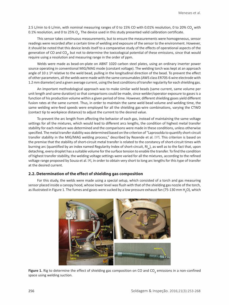
2.2. Determination of the effect of shielding gas compositionFor this study, the welds were made using a special setup, which consisted of a torch and gas measuring
sensor placed inside a canopy hood, whose lower level was flush with that of the shielding gas nozzle of the torch, as illustrated in Figure 1. The fumes and gases were sucked by a low pressure exhaust fan (75-130 mm H2O), which
Figure 1. Rig to determine the effect of shielding gas composition on CO and CO2 emissions in a non-confined space using welding suction.

Soldagem & Inspeção. 2016;21(3):253-268 257
Influence of Metal Transfer Stability and Shielding Gas Composition on CO and CO2 Emissions During Short-circuiting MIG/MAG Welding
directed them towards the sensor. This condition is similar in practice to that of operations that use exhaust hoods over the workstation or at the torch nozzle. The rotating table enabled automated welding, keeping the torch stationary at a given contact tip to workpiece distance (CTWD). Welds were made with 4 different shielding gases, namely, Ar+8%CO2, Ar+25%CO2, Ar+5%O2 and 100%CO2, at a flow rate of 14 l/min.
The conditions of the highest transfer stabilities were determined for a given desired average welding current chosen arbitrarily as Im = 175 + 2 A (keeping the inductive factor set of the welding power source at the intermediate position). The welding parameters for each of the voltage settings were measured and the regularity indices (RIsc) were calculated, keeping in mind that the lower this index the more regular and stable the transfer. Table 1 shows the parameters set and monitored for the tests in the conditions of greatest transfer regularity for each shielding gas. Each condition was done three times. Note that the objective of having for all welds the same average current by adjusting the CTWD was reached. Note also that the voltage setting differs for each gas, aiming to obtain the best regularity. Even in the condition of highest regularity, different gases provide different values of transfer regularity (RIsc); the worst regularity occurred with shielding of 100% CO2.
Table 1. Test parameters to determine the concentrations of CO2 and CO (effect of the shielding gas).
Shielding gas(14 l/min)
Settings Monitored
RIscU(V)
WFS(m/min)
TS(cm/min)
CTWD(mm)
Umean(V)
Imean(A)
Ar+8%CO2 19 3.60 20.8 12 18.3 ± 0.0 174.4 ± 0.3 0.93 ± 0.03
Ar+25%CO2 20 3.60 20.8 14 19.0 ± 0.0 173.6 ± 0.1 1.09 ± 0.09
100%CO2 24 3.60 20.8 9 23.1 ± 0.1 175.8 ± 0.4 1.40 ± 0.01
Ar+5%O2 19 3.60 20.8 13 18.2 ±0.0 175.2 ± 2.0 0.92 ± 0.12
Table 2. CO, CO2 and O2 concentrations measured in the proximity of the sensor as a function of welding time (effect of shielding gas).
Shielding gas(14 l/min)
Time (s) / Concentration (Vol.%)
20 25
CO2 CO O2 CO2 CO O2
Ar+8%CO2 2.7 ± 0.1 0.30 ± 0.00 14.5 ± 0.4 2.8 ± 0.1 0.30 ± 0.00 14.0 ± 0.3
Ar+25%CO2 7.2 ± 0.7 0.50 ± 0.00 14.0 ± 0.7 7.3 ± 0.4 0.50 ± 0.10 13.8 ± 0.5
100%CO2 38.9 ± 1.4 1.00 ± 0.00 11.8 ± 0.5 41.1 ± 4.2 1.20 ± 0.20 10.9 ± 1.0
Ar+5%O2 0.0 ± 0.0 0.00 ± 0.00 19.5 ± 0.4 0.0 ± 0.0 0.01 ± 0.00 17.8 ± 0.6
Table 2 lists the CO, CO2 and O2 levels measured in each condition described in Table 1 (resulting from three replicates). The gas concentrations were measured at two times (at 20 and 25 s), to check the tendency for the concentration levels to continue. O2 was measured to get an idea of the dilution of the gases generated by the arc in the surrounding environment. Taking the case of 100%CO2 shielding, since only a small percentage of CO was measured, it was concluded that the decomposition of CO2 in the area was not large, thus releasing low levels of O2. A calculation of the balance of gas in the measured atmosphere therefore led to the conclusion that 50% or slightly more of this atmosphere consisted of environmental gas sucked into the exhaust system. The decomposition of environmental gas through heat and infrared radiation should generate other types of gases, such as nitrous oxide or ozone, as suggested in the literature, but they could not be measured in this study. This proportion changes slightly with the use of other shielding gases, which is explained by the differences in their physicochemical properties. Nevertheless, the experiment demonstrated an unconfined environment with forced exhaustion. When shielding gas without CO2 was used (Ar+5%O2), no CO2 or CO was present in the measurement zone, indicating the suitability of the experimental setup.
Table 2 also shows that the increasing the data collection time did not affect the tendency and that the standard deviation of each of the three measurements for each welding condition was very low. Again, these two factors indicated that the canopy hood with the exhaust fan was adequate for the proposed purpose. As expected,
Meneses et al.
258 Soldagem & Inspeção. 2016;21(3):253-268
the richer the CO2 shielding gas composition the more CO and CO2 are generated by the arc. In the case of CO2, shielding with 100%CO2 generated 5.7 times more CO2 in the environment, and potentially in the welder’s breathing zone, than the Ar+25%CO2 mixture, even though the composition of this shielding gas had only a 4-fold higher CO2 content. This relationship also holds true when one compares the generation of 100%CO2 shielding gas and that of the Ar+8%CO2 shielding gas, since the former generated 14.7 times more CO2 although its proportion in the composition of the shielding gas was only 12.5 times higher. As for the generation of CO, the higher proportion of CO2 in the 100%CO2 shielding gas is only 2.4-fold higher than with Ar+25%CO2 shielding and 4.2-fold higher than with Ar+8%CO2 shielding.
The fact that a lower volume concentration of CO than of CO2 was generated indicates that only a small portion of the shielding gas was transformed into CO in the arc and persisted in this combination outside the arc. However, the CO2 level attained in the measurement zone reached 40% in the atmosphere when using 100%CO2 shielding, which is a very high level (asphyxiating gas), considering there was only about 11% of O2 in the same zone. Of course, the remainder is the air drawn by the arc to the environment (which includes nitrogen). Also as expected, the use of a shielding gas without the presence of CO2 (Ar+O2) or with low CO2 content is, from the standpoint of generating gas into the atmosphere, less harmful to the worker’s health and to that of the environment.
2.3. Determination of the effect of metal transfer stability
It is important to emphasize that the results described in section 2.2 are normalized, considering that, with each shielding gas, the welds were made using the same level of current and voltage and CTWD settings that would ensure the greatest transfer regularity, i.e., ideal working conditions. It therefore remained to be determined whether different levels of CO and CO2 would be generated to the environment when working under conditions other than that of the greatest transfer regularity.
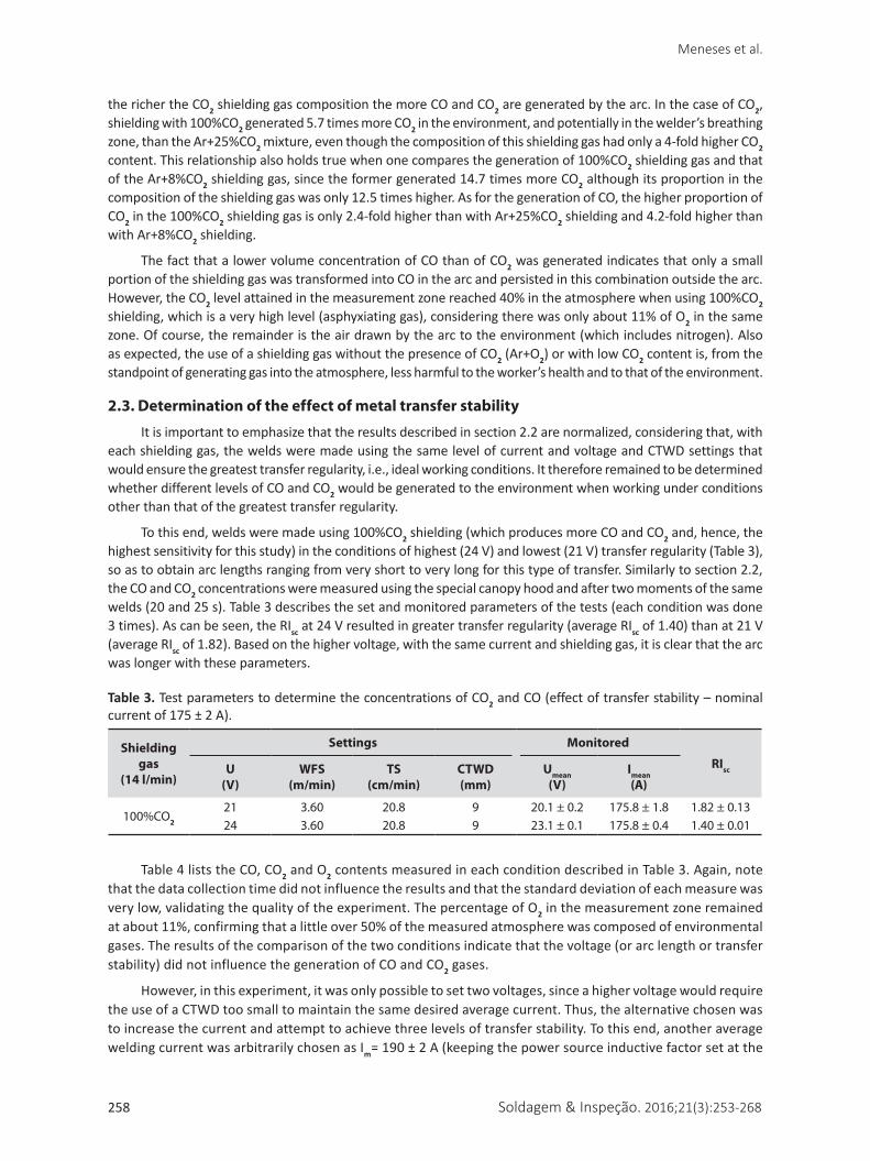
To this end, welds were made using 100%CO2 shielding (which produces more CO and CO2 and, hence, the highest sensitivity for this study) in the conditions of highest (24 V) and lowest (21 V) transfer regularity (Table 3), so as to obtain arc lengths ranging from very short to very long for this type of transfer. Similarly to section 2.2, the CO and CO2 concentrations were measured using the special canopy hood and after two moments of the same welds (20 and 25 s). Table 3 describes the set and monitored parameters of the tests (each condition was done 3 times). As can be seen, the RIsc at 24 V resulted in greater transfer regularity (average RIsc of 1.40) than at 21 V (average RIsc of 1.82). Based on the higher voltage, with the same current and shielding gas, it is clear that the arc was longer with these parameters.
Table 3. Test parameters to determine the concentrations of CO2 and CO (effect of transfer stability – nominal current of 175 ± 2 A).
Shielding gas
(14 l/min)
Settings Monitored
RIscU(V)
WFS(m/min)
TS(cm/min)
CTWD(mm)
Umean(V)
Imean(A)
100%CO2
21 3.60 20.8 9 20.1 ± 0.2 175.8 ± 1.8 1.82 ± 0.1324 3.60 20.8 9 23.1 ± 0.1 175.8 ± 0.4 1.40 ± 0.01
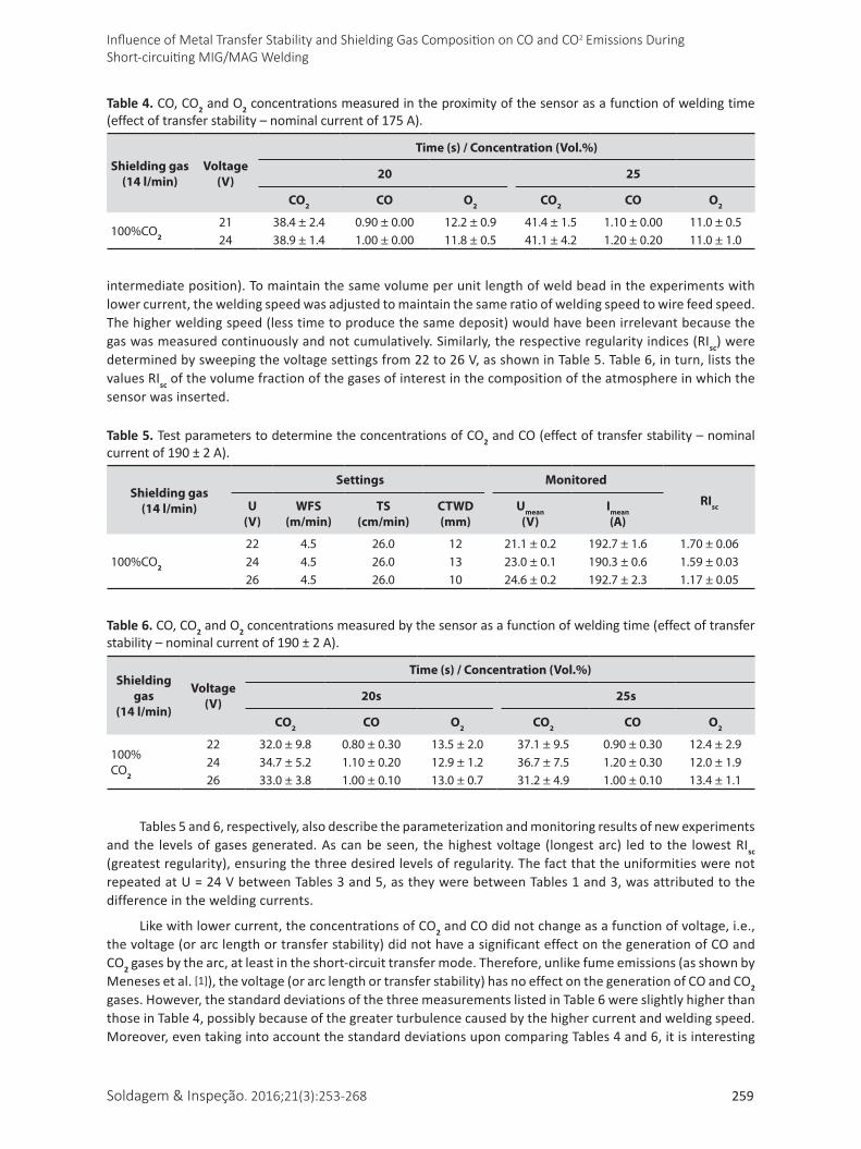
Table 4 lists the CO, CO2 and O2 contents measured in each condition described in Table 3. Again, note that the data collection time did not influence the results and that the standard deviation of each measure was very low, validating the quality of the experiment. The percentage of O2 in the measurement zone remained at about 11%, confirming that a little over 50% of the measured atmosphere was composed of environmental gases. The results of the comparison of the two conditions indicate that the voltage (or arc length or transfer stability) did not influence the generation of CO and CO2 gases.
However, in this experiment, it was only possible to set two voltages, since a higher voltage would require the use of a CTWD too small to maintain the same desired average current. Thus, the alternative chosen was to increase the current and attempt to achieve three levels of transfer stability. To this end, another average welding current was arbitrarily chosen as Im= 190 ± 2 A (keeping the power source inductive factor set at the
Soldagem & Inspeção. 2016;21(3):253-268 259
Influence of Metal Transfer Stability and Shielding Gas Composition on CO and CO2 Emissions During Short-circuiting MIG/MAG Welding
intermediate position). To maintain the same volume per unit length of weld bead in the experiments with lower current, the welding speed was adjusted to maintain the same ratio of welding speed to wire feed speed. The higher welding speed (less time to produce the same deposit) would have been irrelevant because the gas was measured continuously and not cumulatively. Similarly, the respective regularity indices (RIsc) were determined by sweeping the voltage settings from 22 to 26 V, as shown in Table 5. Table 6, in turn, lists the values RIsc of the volume fraction of the gases of interest in the composition of the atmosphere in which the sensor was inserted.
Table 4. CO, CO2 and O2 concentrations measured in the proximity of the sensor as a function of welding time (effect of transfer stability – nominal current of 175 A).
Shielding gas (14 l/min)
Voltage (V)
Time (s) / Concentration (Vol.%)
20 25
CO2 CO O2 CO2 CO O2
100%CO2
21 38.4 ± 2.4 0.90 ± 0.00 12.2 ± 0.9 41.4 ± 1.5 1.10 ± 0.00 11.0 ± 0.524 38.9 ± 1.4 1.00 ± 0.00 11.8 ± 0.5 41.1 ± 4.2 1.20 ± 0.20 11.0 ± 1.0
Table 5. Test parameters to determine the concentrations of CO2 and CO (effect of transfer stability – nominal current of 190 ± 2 A).
Shielding gas(14 l/min)
Settings Monitored
RIscU(V)
WFS(m/min)
TS(cm/min)
CTWD(mm)
Umean(V)
Imean(A)
100%CO2
22 4.5 26.0 12 21.1 ± 0.2 192.7 ± 1.6 1.70 ± 0.0624 4.5 26.0 13 23.0 ± 0.1 190.3 ± 0.6 1.59 ± 0.0326 4.5 26.0 10 24.6 ± 0.2 192.7 ± 2.3 1.17 ± 0.05
Table 6. CO, CO2 and O2 concentrations measured by the sensor as a function of welding time (effect of transfer stability – nominal current of 190 ± 2 A).
Shielding gas
(14 l/min)
Voltage (V)
Time (s) / Concentration (Vol.%)
20s 25s
CO2 CO O2 CO2 CO O2
100%CO2
22 32.0 ± 9.8 0.80 ± 0.30 13.5 ± 2.0 37.1 ± 9.5 0.90 ± 0.30 12.4 ± 2.924 34.7 ± 5.2 1.10 ± 0.20 12.9 ± 1.2 36.7 ± 7.5 1.20 ± 0.30 12.0 ± 1.926 33.0 ± 3.8 1.00 ± 0.10 13.0 ± 0.7 31.2 ± 4.9 1.00 ± 0.10 13.4 ± 1.1
Tables 5 and 6, respectively, also describe the parameterization and monitoring results of new experiments and the levels of gases generated. As can be seen, the highest voltage (longest arc) led to the lowest RIsc (greatest regularity), ensuring the three desired levels of regularity. The fact that the uniformities were not repeated at U = 24 V between Tables 3 and 5, as they were between Tables 1 and 3, was attributed to the difference in the welding currents.
Like with lower current, the concentrations of CO2 and CO did not change as a function of voltage, i.e., the voltage (or arc length or transfer stability) did not have a significant effect on the generation of CO and CO2 gases by the arc, at least in the short-circuit transfer mode. Therefore, unlike fume emissions (as shown by Meneses et al. [1]), the voltage (or arc length or transfer stability) has no effect on the generation of CO and CO2 gases. However, the standard deviations of the three measurements listed in Table 6 were slightly higher than those in Table 4, possibly because of the greater turbulence caused by the higher current and welding speed. Moreover, even taking into account the standard deviations upon comparing Tables 4 and 6, it is interesting
Meneses et al.
260 Soldagem & Inspeção. 2016;21(3):253-268
to note that there is a tendency for CO2 to decrease and O2 to increase when welding with higher currents. This finding supports the hypothesis of greater turbulence of the atmosphere in the measured region, although it could also be the effect of the greater decomposition of CO2 due to greater heat/radiation. Therefore, as the purpose of the experimental test was not to evaluate the effect of current, this finding is indicative rather than conclusive.
2.4. Determination of CO and CO2 concentrations in different welder exposure zones in semi-automatic welding in an open environment
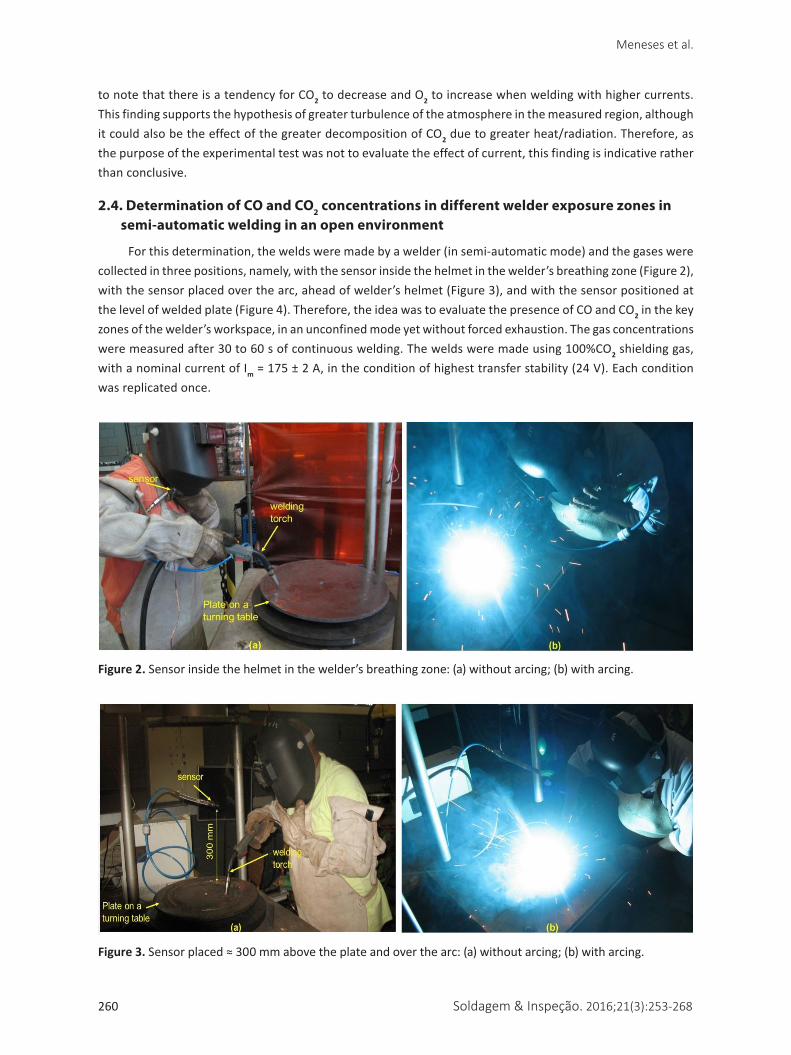
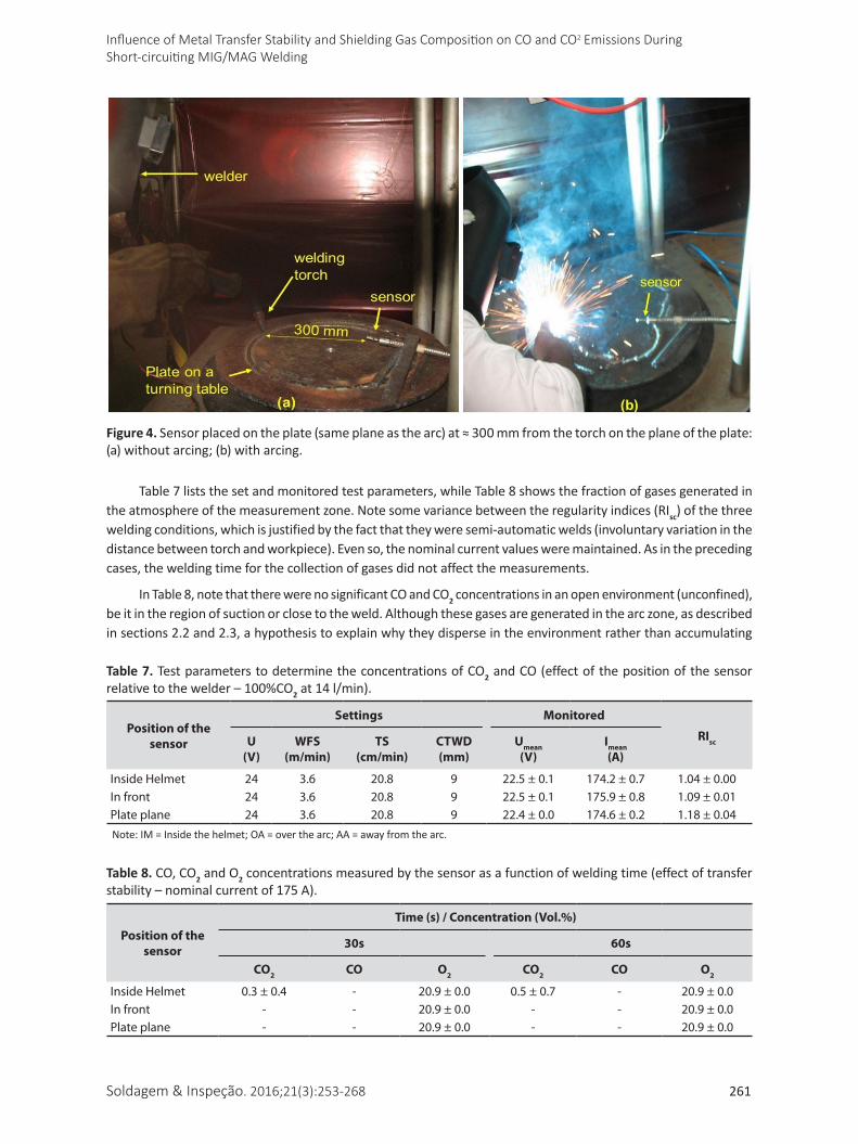
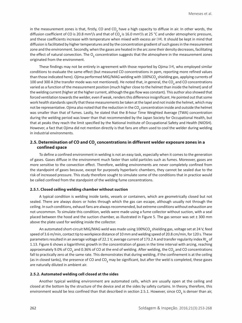
For this determination, the welds were made by a welder (in semi-automatic mode) and the gases were collected in three positions, namely, with the sensor inside the helmet in the welder’s breathing zone (Figure 2), with the sensor placed over the arc, ahead of welder’s helmet (Figure 3), and with the sensor positioned at the level of welded plate (Figure 4). Therefore, the idea was to evaluate the presence of CO and CO2 in the key zones of the welder’s workspace, in an unconfined mode yet without forced exhaustion. The gas concentrations were measured after 30 to 60 s of continuous welding. The welds were made using 100%CO2 shielding gas, with a nominal current of Im = 175 ± 2 A, in the condition of highest transfer stability (24 V). Each condition was replicated once.
Figure 3. Sensor placed ≈ 300 mm above the plate and over the arc: (a) without arcing; (b) with arcing.
Figure 2. Sensor inside the helmet in the welder’s breathing zone: (a) without arcing; (b) with arcing.
Soldagem & Inspeção. 2016;21(3):253-268 261
Influence of Metal Transfer Stability and Shielding Gas Composition on CO and CO2 Emissions During Short-circuiting MIG/MAG Welding
Table 7 lists the set and monitored test parameters, while Table 8 shows the fraction of gases generated in the atmosphere of the measurement zone. Note some variance between the regularity indices (RIsc) of the three welding conditions, which is justified by the fact that they were semi-automatic welds (involuntary variation in the distance between torch and workpiece). Even so, the nominal current values were maintained. As in the preceding cases, the welding time for the collection of gases did not affect the measurements.
In Table 8, note that there were no significant CO and CO2 concentrations in an open environment (unconfined), be it in the region of suction or close to the weld. Although these gases are generated in the arc zone, as described in sections 2.2 and 2.3, a hypothesis to explain why they disperse in the environment rather than accumulating
Table 7. Test parameters to determine the concentrations of CO2 and CO (effect of the position of the sensor relative to the welder – 100%CO2 at 14 l/min).
Position of the sensor
Settings Monitored
RIscU(V)
WFS(m/min)
TS(cm/min)
CTWD(mm)
Umean(V)
Imean(A)
Inside Helmet 24 3.6 20.8 9 22.5 ± 0.1 174.2 ± 0.7 1.04 ± 0.00In front 24 3.6 20.8 9 22.5 ± 0.1 175.9 ± 0.8 1.09 ± 0.01Plate plane 24 3.6 20.8 9 22.4 ± 0.0 174.6 ± 0.2 1.18 ± 0.04Note: IM = Inside the helmet; OA = over the arc; AA = away from the arc.
Table 8. CO, CO2 and O2 concentrations measured by the sensor as a function of welding time (effect of transfer stability – nominal current of 175 A).
Position of the sensor
Time (s) / Concentration (Vol.%)
30s 60s
CO2 CO O2 CO2 CO O2
Inside Helmet 0.3 ± 0.4 - 20.9 ± 0.0 0.5 ± 0.7 - 20.9 ± 0.0In front - - 20.9 ± 0.0 - - 20.9 ± 0.0Plate plane - - 20.9 ± 0.0 - - 20.9 ± 0.0
Figure 4. Sensor placed on the plate (same plane as the arc) at ≈ 300 mm from the torch on the plane of the plate: (a) without arcing; (b) with arcing.
Meneses et al.
262 Soldagem & Inspeção. 2016;21(3):253-268
in the measurement zones is that, firstly, CO and CO2 have a high capacity to diffuse in air. In other words, the diffusion coefficient of CO is 20.8 mm2/s and that of CO2 is 16.0 mm2/s at 25 °C and under atmospheric pressure, and these coefficients increase with temperature when mixed with excess air [18]. It should be kept in mind that diffusion is facilitated by higher temperatures and by the concentration gradient of such gases in the measurement zone and the environment. Secondly, when the gases are heated in the arc zone their density decreases, facilitating the effect of natural convection. The O2 concentration suggests that the atmosphere in the measurement zones originated from the environment.
These findings may not be entirely in agreement with those reported by Ojima [14], who employed similar conditions to evaluate the same effect (but measured CO concentrations in ppm, reporting more refined values than those indicated here). Ojima performed MIG/MAG welding with 100%CO2 shielding gas, applying currents of 100 and 300 A (the transfer mode was not mentioned). He noted that, in general, the CO2 and CO concentrations varied as a function of the measurement position (much higher close to the helmet than inside the helmet) and of the welding current (higher at the higher current, although the gas flow was constant). This author also showed that forced ventilation towards the welder, even if weak, renders this difference insignificant. He pointed out that some work health standards specify that these measurements be taken at the lapel and not inside the helmet, which may not be representative. Ojima also noted that the reduction in the CO2 concentration inside and outside the helmet was smaller than that of fumes. Lastly, he stated that the 8-hour Time Weighted Average (TWA) concentration during the welding period was lower than that recommended by the Japan Society for Occupational Health, but that at peaks they reach the limit specified by the National Institute of Occupational Safety and Health (NIOSH). However, a fact that Ojima did not mention directly is that fans are often used to cool the welder during welding in industrial environments.
2.5. Determination of CO and CO2 concentrations in different welder exposure zones in a confined space
To define a confined environment in welding is not an easy task, especially when it comes to the generation of gases. Gases diffuse in the environment much faster than solid particles such as fumes. Moreover, gases are more sensitive to the convection effect. Therefore, welding environments are never completely confined from the standpoint of gases because, except for purposely hyperbaric chambers, they cannot be sealed due to the risk of increased pressure. This study therefore sought to simulate some of the conditions that in practice would be called confined from the standpoint of the welding fume concentrations.
2.5.1. Closed ceiling welding chamber without suction
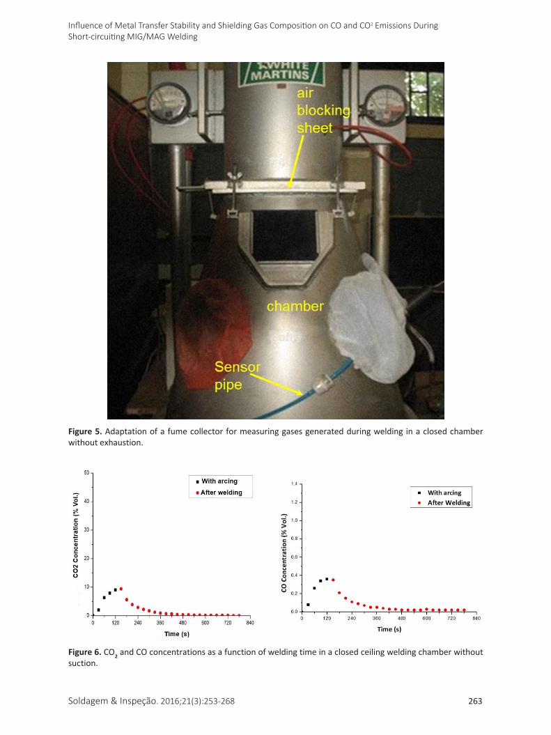
A typical condition is welding inside tanks, vessels or containers, which are geometrically closed but not sealed. There are always doors or holes through which the gas can escape, although usually not through the ceiling. In such conditions, exhaust fans are always recommended, but extreme conditions without exhaustion are not uncommon. To simulate this condition, welds were made using a fume collector without suction, with a seal placed between the hood and the suction chamber, as illustrated in Figure 5. The gas sensor was set ± 300 mm above the plate used for welding inside the collector.
An automated short-circuit MIG/MAG weld was made using 100%CO2 shielding gas, voltage set at 24 V, feed speed of 3.6 m/min, contact tip to workpiece distance of 10 mm and welding speed of 20.8 cm/min, for 120 s. These parameters resulted in an average voltage of 22.1 V, average current of 173.2 A and transfer regularity index RIsc of 1.13. Figure 6 shows a logarithmic growth in the concentration of gases in the time interval with arcing, reaching approximately 9.0% of CO2 and 0.36% of CO at the end of welding. After welding, the CO2 and CO concentrations fall to practically zero at the same rate. This demonstrates that during welding, if the confinement is at the ceiling (as in closed tanks), the presence of CO and CO2 may be significant, but after the weld is completed, these gases are naturally diluted in ambient air.
2.5.2. Automated welding cell closed at the sides
Another typical welding environment are automated cells, which are usually open at the ceiling and closed at the bottom by the structure of the device and at the sides by safety curtains. In theory, therefore, this environment would be less confined than that described in section 2.5.1. However, since CO2 is denser than air,
Soldagem & Inspeção. 2016;21(3):253-268 263
Influence of Metal Transfer Stability and Shielding Gas Composition on CO and CO2 Emissions During Short-circuiting MIG/MAG Welding
Figure 5. Adaptation of a fume collector for measuring gases generated during welding in a closed chamber without exhaustion.
Figure 6. CO2 and CO concentrations as a function of welding time in a closed ceiling welding chamber without suction.
Meneses et al.
264 Soldagem & Inspeção. 2016;21(3):253-268
unlike CO (in normal conditions of temperature and pressure, i.e., 20 °C and 1 atm, the density of air is 1,205, that of CO2 is 1,842 and that of CO is 1,165kg/m3), although CO2 disperses, it could accumulate in the lower parts of the cell after long welding times before it diffuses through the environment.
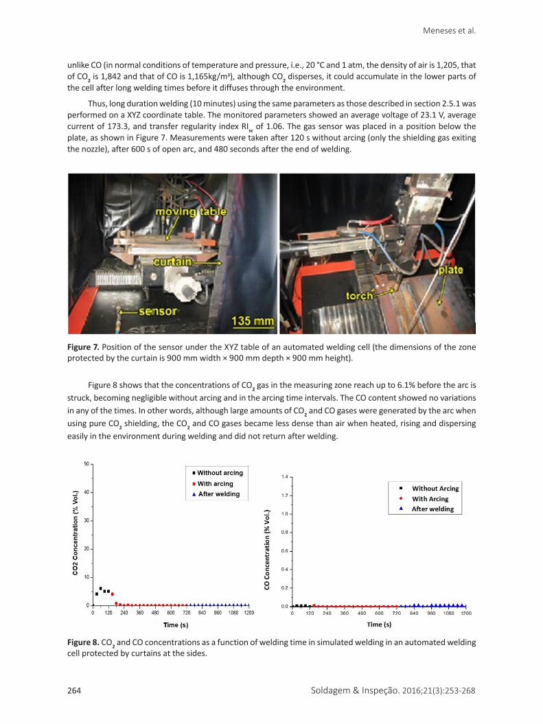
Thus, long duration welding (10 minutes) using the same parameters as those described in section 2.5.1 was performed on a XYZ coordinate table. The monitored parameters showed an average voltage of 23.1 V, average current of 173.3, and transfer regularity index RIsc of 1.06. The gas sensor was placed in a position below the plate, as shown in Figure 7. Measurements were taken after 120 s without arcing (only the shielding gas exiting the nozzle), after 600 s of open arc, and 480 seconds after the end of welding.
Figure 8 shows that the concentrations of CO2 gas in the measuring zone reach up to 6.1% before the arc is struck, becoming negligible without arcing and in the arcing time intervals. The CO content showed no variations in any of the times. In other words, although large amounts of CO2 and CO gases were generated by the arc when using pure CO2 shielding, the CO2 and CO gases became less dense than air when heated, rising and dispersing easily in the environment during welding and did not return after welding.
Figure 7. Position of the sensor under the XYZ table of an automated welding cell (the dimensions of the zone protected by the curtain is 900 mm width × 900 mm depth × 900 mm height).
Figure 8. CO2 and CO concentrations as a function of welding time in simulated welding in an automated welding cell protected by curtains at the sides.
Soldagem & Inspeção. 2016;21(3):253-268 265
Influence of Metal Transfer Stability and Shielding Gas Composition on CO and CO2 Emissions During Short-circuiting MIG/MAG Welding
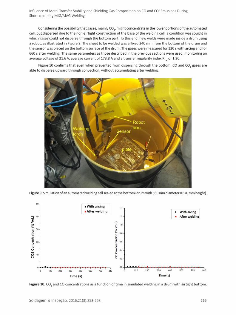
Considering the possibility that gases, mainly CO2, might concentrate in the lower portions of the automated cell, but dispersed due to the non-airtight construction of the base of the welding cell, a condition was sought in which gases could not disperse through the bottom part. To this end, new welds were made inside a drum using a robot, as illustrated in Figure 9. The sheet to be welded was affixed 240 mm from the bottom of the drum and the sensor was placed on the bottom surface of the drum. The gases were measured for 120 s with arcing and for 660 s after welding. The same parameters as those described in the previous sections were used, monitoring an average voltage of 21.6 V, average current of 173.8 A and a transfer regularity index RIsc of 1.20.
Figure 10 confirms that even when prevented from dispersing through the bottom, CO and CO2 gases are able to disperse upward through convection, without accumulating after welding.
Figure 9. Simulation of an automated welding cell sealed at the bottom (drum with 560 mm diameter × 870 mm height).
Figure 10. CO2 and CO concentrations as a function of time in simulated welding in a drum with airtight bottom.
Meneses et al.
266 Soldagem & Inspeção. 2016;21(3):253-268
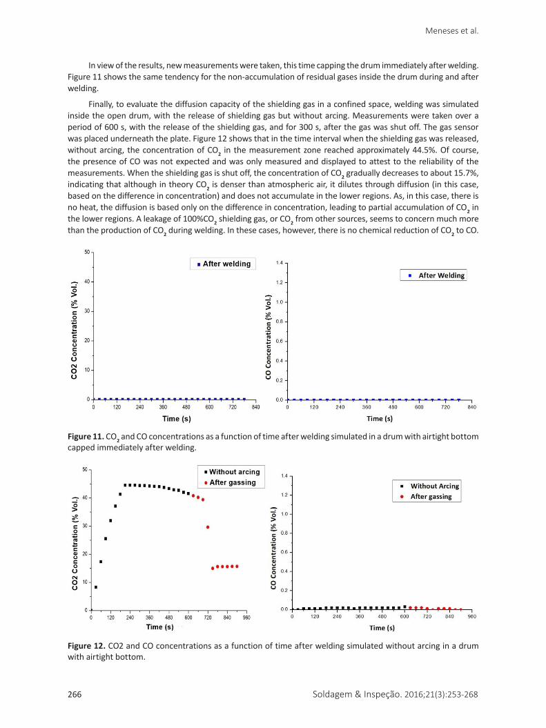
In view of the results, new measurements were taken, this time capping the drum immediately after welding. Figure 11 shows the same tendency for the non-accumulation of residual gases inside the drum during and after welding.
Finally, to evaluate the diffusion capacity of the shielding gas in a confined space, welding was simulated inside the open drum, with the release of shielding gas but without arcing. Measurements were taken over a period of 600 s, with the release of the shielding gas, and for 300 s, after the gas was shut off. The gas sensor was placed underneath the plate. Figure 12 shows that in the time interval when the shielding gas was released, without arcing, the concentration of CO2 in the measurement zone reached approximately 44.5%. Of course, the presence of CO was not expected and was only measured and displayed to attest to the reliability of the measurements. When the shielding gas is shut off, the concentration of CO2 gradually decreases to about 15.7%, indicating that although in theory CO2 is denser than atmospheric air, it dilutes through diffusion (in this case, based on the difference in concentration) and does not accumulate in the lower regions. As, in this case, there is no heat, the diffusion is based only on the difference in concentration, leading to partial accumulation of CO2 in the lower regions. A leakage of 100%CO2 shielding gas, or CO2 from other sources, seems to concern much more than the production of CO2 during welding. In these cases, however, there is no chemical reduction of CO2 to CO.
Figure 12. CO2 and CO concentrations as a function of time after welding simulated without arcing in a drum with airtight bottom.
Figure 11. CO2 and CO concentrations as a function of time after welding simulated in a drum with airtight bottom capped immediately after welding.
Soldagem & Inspeção. 2016;21(3):253-268 267
Influence of Metal Transfer Stability and Shielding Gas Composition on CO and CO2 Emissions During Short-circuiting MIG/MAG Welding
3. Conclusions
The results of this work lead to the conclusion that short-circuit MIG/MAG welding of carbon steel, because it allows for the use of CO2 shielding gas, emits significant amounts of CO2 (asphyxiating) and CO (toxic) gases in the welding region during operation. However, this emission is independent of the metal transfer stability and arc length used. The richer the shielding gas mixture is in CO2 the higher this emission, reaching significant levels when using 100% CO2 as shielding gas. The use of Ar (argon) based mixtures with lower percentages of CO2 or with O2 proved to be an acceptable alternative also from other operational standpoints.
On the other hand, the conversion of CO2 in the arc in short-circuit transfer was found to be negligible, causing the emission of CO to be relatively low. Furthermore, due to the diffusion capacity of CO2 and CO in atmospheric air, the emitted gases are not concentrated, at least in quantifiable levels higher than tenths and hundredths of volume percentages, after welding in the work envelope of a welder, even in spaces considered confined. Concentration of CO2 in the working area can happen, however, if there is no heating to facilitate the diffusion of this gas. Other sources of CO2 worry more than arc welding in confined area.
Considering these conclusions, three multidisciplinary aspects are objectives for future studies. The first would focus on workers’ health. The study would involve determining if the welder might be exposed to unacceptable levels of CO and CO2 (quantified in ppm) during their emission, even considering the herein demonstrated rapid dispersion of these gases from the work area after the end of welding. The second aspect, related to the environment, would be to evaluate the contribution of the amount of CO2 generated in welding processes to the enrichment of the concentration of CO2 in the environment, and the consequent effects on environmental imbalance, given that welding is a widely applied manufacturing process in both industrialized and developing countries. The third aspect, of a more operational nature, would be to study the effect of other welding variables, such as current and other transfer modes, on the generation of these gases. Given the interdisciplinary nature of these studies, the natural way would be through cooperative projects supported by government and suppliers or users of the process.
Acknowledgements
The authors thank the Center for Research and Development of Welding Processes (Laprosolda) of the Federal University of Uberlândia – UFU for allowing them to use its equipment and for providing technical support. We also thank CAPES (UFU-IFMA Dinter Program) and CNPq for awarding study and research grants.
References[1] Meneses VA, Gomes JFP, Scotti A. The effect of metal transfer
stability (spattering) on fume generation, morphology and composition in Short-Circuit MAG Welding. Journal of Materials Processing Technology. 2014;214(7):1388-1397. http://dx.doi.org/10.1016/j.jmatprotec.2014.02.012.
[2] Liskevych O, Scotti A. Influence of the CO2 content on operational performance of short-circuit GMAW. Welding in the World. 2015;59(2):217-224. http://dx.doi.org/10.1007/s40194-014-0196-x.
[3] Scotti A, Ponomarev V, Lucas W. A scientific application oriented classification for metal transfer modes in GMA welding. Journal of Materials Processing Technology. 2012;212(6):1406-1413. http://dx.doi.org/10.1016/j.jmatprotec.2012.01.021.
[4] Souza D, Rossi ML, Keocheguerians F, Nascimento VC, Vilarinho LO, Scotti A. Influência da regulagem de parâmetros de soldagem sobre a estabilidade do processo MIG/MAG operando em curto-circuito. Soldagem & Inspeção. 2011;16(1):22-32. http://dx.doi.org/10.1590/S0104-92242011000100004.
[5] Zielinska S, Pellerin S, Valensi F, Dzierzega K, Musiol K, de Izarra C, et al. Gas influence on the arc shape in MIG–MAG welding. Eur Phys J AP. 2008;43(1):111-122. http://dx.doi.org/10.1051/epjap:2008106.
[6] Stenbacka N, Persson KA. Shielding gases for gas metal arc welding. Welding Journal. 1989;68(11):41-48.
[7] Soderstrom E, Mendez PF. Metal transfer during GMAW with thin electrodes. Welding Journal. 2008;87(5):124s-133.
[8] Hermans MJM, den Ouden G. Process behavior and stability in short circuit gas metal arc welding. Welding Journal. 1999;78(4):137-141.
[9] Kim Y-S, Eagar TW. Analysis of metal transfer in gas metal arc welding. Welding Journal. 1993;72(1):269-278.
[10] Rhee S, Kannatey-Asibu E. Observation of metal transfer during gas metal arc welding. Welding Journal. 1992;71(3):381s-386s.
[11] Jacobsen N. Monopulse investigation of drop detachment in pulsed gas metal arc welding. Journal of Physics. D, Applied Physics. 1992;25(5):783-797. http://dx.doi.org/10.1088/0022-3727/25/5/007.
[12] Antonini JM, Santamaria AB, Jenkins NT, Albini E, Lucchini R. Fate of manganese associated with the inhalation of welding: potential neurological effects. Neurotoxicology. 2006;27(3):304-310. http://dx.doi.org/10.1016/j.neuro.2005.09.001. PMid:16219356.
[13] Yeo SH, Neo KG. Inclusion of environmental performance for decision making of welding processes. Journal of Materials Processing Technology. 1998;82(1-3):78-88. http://dx.doi.org/10.1016/S0924-0136(98)00022-3.
[14] Ojima J. Laboratory evaluation of carbon monoxide exposure in CO2 arc welding. Journal of Occupational Health. 2009;51(4):377-379. http://dx.doi.org/10.1539/joh.M9004. PMid:19502769.
Meneses et al.
268 Soldagem & Inspeção. 2016;21(3):253-268
[15] Matusiak J, Rams B. Emission of dust and gases in tubular cored wire welding of steel. International Journal of Occupational Safety and Ergonomics. 2003;9(3):333-350. http://dx.doi.org/10.1080/10803548.2003.11076572. PMid:14577949.
[16] National Institute for Occupational Safety and Health. Nomination of welding fumes for toxicity studies. Washington: NIOSH; 2002.
[17] Rezende GMC, Liskévych O, Vilarinho LO, Scotti A. Um critério para determinar a regulagem da tensão em soldagem MIG/MAG por curto-circuito. Soldagem & Inspeção. 2011;16(2):98-103.
[18] University of California. Diffusion in gases. Santa Barbara: UCSB; 2015. [access 5 june 2015]. Available from: http://www2.bren.ucsb.edu/~dturney/WebResources_13/GasInWaterProperties_files/BinaryDiffusionOfGases.pdf