Influence of Coalescence on the Anisotropic Mechanical...
11
materials Article Influence of Coalescence on the Anisotropic Mechanical and Electrical Properties of Nickel Powder/Polydimethylsiloxane Composites Sung-Hwan Jang 1,2, *, Yong-Lae Park 1,3 and Huiming Yin 2 1 Robotics Institute, School of Computer Science, Carnegie Mellon University, Pittsburgh, PA 15213, USA; [email protected] 2 Department of Civil Engineering and Engineering Mechanics, Columbia University, New York, NY 10027, USA; [email protected] 3 Department of Mechanical and Aerospace Engineering, Seoul National University, Seoul 08826, Korea * Correspondence: [email protected]; Tel.: +1-917-741-5328 Academic Editor: Changle Chen Received: 18 January 2016; Accepted: 24 March 2016; Published: 29 March 2016 Abstract: Multifunctional polymer-based composites have been widely used in various research and industrial applications, such as flexible and stretchable electronics and sensors and sensor-integrated smart structures. This study investigates the influence of particle coalescence on the mechanical and electrical properties of spherical nickel powder (SNP)/polydimethylsiloxane (PDMS) composites in which SNP was aligned using an external magnetic field. With the increase of the volume fraction of the SNP, the aligned SNP/PDMS composites exhibited a higher tensile strength and a lower ultimate strain. In addition, the composites with aligned SNP showed a lower percolation threshold and a higher electrical conductivity compared with those with randomly dispersed SNP. However, when the concentration of the SNP reached a certain level (40 vol. %), the anisotropy of the effective material property became less noticeable than that of the lower concentration (20 vol. %) composites due to the change of the microstructure of the particles caused by the coalescence of the particles at a high concentration. This work may provide rational methods for the fabrication of aligned composites. Keywords: metal-polymer composite; magnetic field; alignment; coalescence; electrical conductivity; mechanical property 1. Introduction Conductive polymer composites [1–5] have been recently explored and implemented in applications of flexible sensors and sensor-integrated smart structures for structural health monitoring in next generation infrastructures [6–8]. Although conventional strain sensors, such as metal-foil or silicon strain gauges, have been widely used for structural health monitoring [9,10], their inherent limitations, such as the requirement of rigid substrates, narrow dynamic ranges, and mechanical fragility, necessitated the development of new types of sensing materials. To overcome these challenges, various types of polymer composites have been proposed using advanced materials, such as ceramics [11,12], ferromagnetic particles [8,13], carbon nanotubes [14–16], and embedded liquid conductors [17–19]. Chun et al. have developed stretchable and flexible conductive films composed of carbon nanotubes and silver flakes for achieving a high conductivity at a high tensile strain (20 S/cm at 140% strain) [20]. Yamada et al. have proposed a carbon nanotube film strain sensor that can be incorporated into the human body [21]. They were able to achieve high strains up to 280% with high durability and a fast response. In addition to the type of embedded conductive filler particles, the alignment of particles using mechanical, electrical, or magnetic forces is also a useful technique to enhance the overall material Materials 2016, 9, 239; doi:10.3390/ma9040239 www.mdpi.com/journal/materials
Transcript of Influence of Coalescence on the Anisotropic Mechanical...

materials
Article
Influence of Coalescence on the AnisotropicMechanical and Electrical Properties of NickelPowder/Polydimethylsiloxane Composites
Sung-Hwan Jang 1,2,*, Yong-Lae Park 1,3 and Huiming Yin 2
1 Robotics Institute, School of Computer Science, Carnegie Mellon University, Pittsburgh, PA 15213, USA;[email protected]
2 Department of Civil Engineering and Engineering Mechanics, Columbia University,New York, NY 10027, USA; [email protected]
3 Department of Mechanical and Aerospace Engineering, Seoul National University, Seoul 08826, Korea* Correspondence: [email protected]; Tel.: +1-917-741-5328
Academic Editor: Changle ChenReceived: 18 January 2016; Accepted: 24 March 2016; Published: 29 March 2016
Abstract: Multifunctional polymer-based composites have been widely used in various research andindustrial applications, such as flexible and stretchable electronics and sensors and sensor-integratedsmart structures. This study investigates the influence of particle coalescence on the mechanical andelectrical properties of spherical nickel powder (SNP)/polydimethylsiloxane (PDMS) composites inwhich SNP was aligned using an external magnetic field. With the increase of the volume fraction ofthe SNP, the aligned SNP/PDMS composites exhibited a higher tensile strength and a lower ultimatestrain. In addition, the composites with aligned SNP showed a lower percolation threshold and ahigher electrical conductivity compared with those with randomly dispersed SNP. However, whenthe concentration of the SNP reached a certain level (40 vol. %), the anisotropy of the effective materialproperty became less noticeable than that of the lower concentration (20 vol. %) composites due tothe change of the microstructure of the particles caused by the coalescence of the particles at a highconcentration. This work may provide rational methods for the fabrication of aligned composites.
Keywords: metal-polymer composite; magnetic field; alignment; coalescence; electrical conductivity;mechanical property
1. Introduction
Conductive polymer composites [1–5] have been recently explored and implemented inapplications of flexible sensors and sensor-integrated smart structures for structural health monitoringin next generation infrastructures [6–8]. Although conventional strain sensors, such as metal-foil orsilicon strain gauges, have been widely used for structural health monitoring [9,10], their inherentlimitations, such as the requirement of rigid substrates, narrow dynamic ranges, and mechanicalfragility, necessitated the development of new types of sensing materials. To overcome thesechallenges, various types of polymer composites have been proposed using advanced materials,such as ceramics [11,12], ferromagnetic particles [8,13], carbon nanotubes [14–16], and embeddedliquid conductors [17–19]. Chun et al. have developed stretchable and flexible conductive filmscomposed of carbon nanotubes and silver flakes for achieving a high conductivity at a high tensilestrain (20 S/cm at 140% strain) [20]. Yamada et al. have proposed a carbon nanotube film strain sensorthat can be incorporated into the human body [21]. They were able to achieve high strains up to 280%with high durability and a fast response.
In addition to the type of embedded conductive filler particles, the alignment of particles usingmechanical, electrical, or magnetic forces is also a useful technique to enhance the overall material
Materials 2016, 9, 239; doi:10.3390/ma9040239 www.mdpi.com/journal/materials

Materials 2016, 9, 239 2 of 11
properties of a composite [22–27]. Since the alignment methods can make the conductive fillers betternetworked and aligned in a desired direction in the matrix, we can obtain improved performancesof the composite in terms of mechanical and electrical properties compared with composites withrandomly dispersed fillers. For instance, Song et al. have aligned a small amount of ferromagneticparticles in epoxy using a magnetic field for improved mechanical properties of the composite, such asYoung’s modulus, tensile, and tear strength [28]. Sun et al. have effectively controlled the alignment andthe orientation of nickel nanowires in polydimethylsiloxane (PDMS) for anisotropic material behaviorsof the composite in both mechanical and magnetic properties [29]. In particular, magnetic alignmenthas been widely used in polymer-based composites with filler particles [30–32]. The chain-structuredparticle alignments are achieved under an external magnetic field due to mutual interactions betweenparticles that are close to each other. Also, the chain-structured particles may coalesce into columnarstructures depending on several factors, such as strength and direction of the external magnetic field,magnetization time, and particle concentrations. The coalescence naturally occurs even in smallvolume fractions of particles because of particle-chain interactions [33]. However, most of the previousreports limited the concentration of filler particles to relatively small (less than 30 vol. %) [8,34] in thecomposite, describing only the effect of the particle alignment on the material’s properties, but nottaking the effect of coalescence into account. Therefore, to fully characterize the material properties ofthis type of composite, a further investigation is needed in a wider range of particle concentrations,including high volume fractions over 30 vol. %, considering the relationship between coalescence andvolume fraction of filler particles.
In this study, we fabricated conductive polymer composites composed of spherical nickelpowder (SNP) and polydimethylsiloxane (PDMS) with different particle concentrations. Differentconcentrations of SNP were aligned in pre-polymer using an external magnetic field during the curingprocess. An optical microscope was used to characterize the alignment and the coalescence of the SNPparticles. The composites were experimentally characterized to evaluate the effect of the coalescenceon the anisotropic material properties with different particle concentrations.
2. Experimental
2.1. Materials and Sample Preparation
PDMS (Sylgard 184) was obtained from Dow Corning (Midland, MI, USA). PDMS is anon-conductive material with a conductivity of approximately 2.0 ˆ 10´14 S/m. Spherical nickelpowder (SNP, SNP-400) was obtained from NOVAMET (Lebanon, TN, USA). The average diameter ofthe SNP is 11.4 µm, and the electrical conductivity is about 1 ˆ 106 S/m. Densities of the PDMS andthe SNP are 0.96 g/cm3 and 8.65 g/cm3, respectively.
After PDMS and as-received SNP were weighed for the target weight fractions (0, 10, 20, 30,and 40 vol. %), they were mixed using a polymer mixer (ARE 301, Thinky Corp., Tokyo, Japan) at2000 rpm for three minutes at room temperature in order to obtain a uniform mixture. After dispersion,a curing agent was added to the mixture at a weight ratio of 10:1 for the elastomer and the curing agent,respectively, and mixed again for another three minutes. The mixture was then degassed in vacuumfor 10 min to eliminate air voids in the matrix and poured into a mold. An external magnetic field(approximately 1.0 Tesla) was applied to the sample for the alignment of SNP at room temperature, asshown in Figure 1a. Finally, the sample was cured in an oven at 120 ˝C for one hour. The samples werekept under the magnetic field for continuous alignment during the entire curing process. After fullycuring, the samples were lifted off from the mold and post-cured at 60 ˝C for 1 h.

Materials 2016, 9, 239 3 of 11Materials 2016, 9, 239 3 of 10
Figure 1. Experimental setup and sample preparation for electrical conductivity and tensile test:
(a) Experimental set-up; and (b) Sample preparation for: (i) electrical conductivity and (ii) tensile test.
2.2. Characterization
The alignment of SNP in the pre-polymer was characterized using an optical microscope. The
direct current (DC) conductivity was measured by a standard two-probe method using two
multimeters. For the electrical conductivity, the samples were cut into 10 mm × 30 mm. The
electrodes were coated with high-purity silver on both sides of the sample to minimize contact
resistances (Figure 1b). Some samples with higher resistances (above 1 GΩ) were measured by a
precision multimeter (Keitheley 6517B, Beaverton, OR, USA) and the others with lower resistance
(below 1 GΩ) was measured using a regular multimeter (Fluke 8845A, Everett, WA, USA). Then, the
electrical conductivity (σ) was calculated as following:
𝜎 =𝐿
𝑅𝐴 (1)
where R is the measured resistance, A is the cross-sectional area of the composite; and L is the length
between the electrodes. Tensile test of the samples was conducted using a motorized materials test
stand (ESM301L, Mark-10) at room temperature according to ASTM D412 [35]. The samples were cut
in a dog-bone shape in two directions, parallel and perpendicular to the applied magnetic field
(Figure 1b). The displacement control was performed and the crosshead velocity was 30.0 mm/min.
Five samples of each material were tested for different sample directions (perpendicular and
parallel) at room temperature.
3. Results and Discussion
Since optical investigation did not make it easy to understand the microstructural change in
particles in the pre-polymer in a three-dimensional (3D) space, we used a 3D dynamic simulation for
the particle alignment in the pre-polymer state. Figure 2 shows the simulation results of SNP
alignment in a 3D space with two different particle concentrations. Although the movement of
magnetic particles is affected by different factors, such as the magnetic force, van der Waals force,
and gravitational and buoyancy forces, the simulation for the particle alignment was established
using Newton’s second law of motion. Total forces include the Stokes’ drag force, dipole-dipole
interaction force, and repulsive force due to contact with other particles and with walls. The
simulation was conducted using the Runge-Kutta algorithm. More details in the simulation can be
found in [36]. In this study, we simulated 30 vol.% of particles for a high volume fraction due to the
computation time.
For the low volume fraction of particles, as shown in Figure 2a, relatively clear chain-like
particle structures were observed without any interaction between other chains. Figure 3 shows
experimental results for the alignment process of the SNP in the matrix according to the
magnetization time. When the external magnetic field was applied, the SNP was quickly aligned in
parallel with the direction of the magnetic field, forming a short-chain structure, and finally making
Figure 1. Experimental setup and sample preparation for electrical conductivity and tensile test:(a) Experimental set-up; and (b) Sample preparation for: (i) electrical conductivity and (ii) tensile test.
2.2. Characterization
The alignment of SNP in the pre-polymer was characterized using an optical microscope.The direct current (DC) conductivity was measured by a standard two-probe method using twomultimeters. For the electrical conductivity, the samples were cut into 10 mm ˆ 30 mm. The electrodeswere coated with high-purity silver on both sides of the sample to minimize contact resistances(Figure 1b). Some samples with higher resistances (above 1 GΩ) were measured by a precisionmultimeter (Keitheley 6517B, Beaverton, OR, USA) and the others with lower resistance (below 1 GΩ)was measured using a regular multimeter (Fluke 8845A, Everett, WA, USA). Then, the electricalconductivity (σ) was calculated as following:
σ “L
RA(1)
where R is the measured resistance, A is the cross-sectional area of the composite; and L is the lengthbetween the electrodes. Tensile test of the samples was conducted using a motorized materials teststand (ESM301L, Mark-10) at room temperature according to ASTM D412 [35]. The samples werecut in a dog-bone shape in two directions, parallel and perpendicular to the applied magnetic field(Figure 1b). The displacement control was performed and the crosshead velocity was 30.0 mm/min.Five samples of each material were tested for different sample directions (perpendicular and parallel)at room temperature.
3. Results and Discussion
Since optical investigation did not make it easy to understand the microstructural change inparticles in the pre-polymer in a three-dimensional (3D) space, we used a 3D dynamic simulation forthe particle alignment in the pre-polymer state. Figure 2 shows the simulation results of SNP alignmentin a 3D space with two different particle concentrations. Although the movement of magnetic particlesis affected by different factors, such as the magnetic force, van der Waals force, and gravitational andbuoyancy forces, the simulation for the particle alignment was established using Newton’s second lawof motion. Total forces include the Stokes’ drag force, dipole-dipole interaction force, and repulsiveforce due to contact with other particles and with walls. The simulation was conducted using theRunge-Kutta algorithm. More details in the simulation can be found in [36]. In this study, we simulated30 vol. % of particles for a high volume fraction due to the computation time.
Materials 2016, 9, 239 4 of 11
Materials 2016, 9, 239 4 of 10
large aggregates with the magnetization time. This occurred due to the magnetization of the
particles, forming a chain structure resulting in thick aggregates [37,38]. Figure 4 shows an
illustration of magnetically induced phase transition with magnetization time. Randomly dispersed
particles exist in the pre-polymer state before applying the magnetic field, as shown in Figure 4a.
When the magnetic field is strong enough, the magnetic moment of the particle reaches a saturated
value, and the dipole-dipole interaction force drives particles into chain-like structures along the
dipole moment, as shown in Figure 4b. Then, when inter-chain repulsive forces are strong enough,
the system becomes thermodynamically unstable and the chains start to aggregate into different
shapes, such as zigzag multi-chains, as shown in Figure 4c [39].
On the other hand, the nickel particles formed lateral coalescence in some places with a higher
concentration, as shown in Figure 2b. Figure 5 presents microscopic images of the SNP in the matrix
with different volume fractions with and without the magnetic field. Figure 5a shows randomly
dispersed SNPs in the matrix without applying the magnetic field. With the magnetic field, nickel
particles were quickly aligned in parallel (Figure 5b). The alignment was clearly observed until the
volume fraction reached 20 vol.% (Figure 5c). However, it was difficult to identify the alignment
pattern with a high volume fraction (Figure 5d) since the average inter-particle distance became
smaller as the particle concentration increased. Moreover, the magnetization of the SNP may also
have attracted the particles to each other, resulting in the rearrangement of the microstructure of the
aligned particles to aggregation in the matrix during the curing process. Therefore, at a high volume
fraction, the particle rearrangement into complex structures was observed under the same external
magnetic field. This change in microstructure may have affected overall material properties such as
electrical and mechanical properties of the aligned SNP/PDMS composite.
Figure 2. 3D simulation results of particle alignments in composite structures; (a) 5 vol.% nickel
particles; and (b) 30 vol.% nickel particles. Figure 2. 3D simulation results of particle alignments in composite structures; (a) 5 vol. % nickelparticles; and (b) 30 vol. % nickel particles.
For the low volume fraction of particles, as shown in Figure 2a, relatively clear chain-like particlestructures were observed without any interaction between other chains. Figure 3 shows experimentalresults for the alignment process of the SNP in the matrix according to the magnetization time. Whenthe external magnetic field was applied, the SNP was quickly aligned in parallel with the directionof the magnetic field, forming a short-chain structure, and finally making large aggregates with themagnetization time. This occurred due to the magnetization of the particles, forming a chain structureresulting in thick aggregates [37,38]. Figure 4 shows an illustration of magnetically induced phasetransition with magnetization time. Randomly dispersed particles exist in the pre-polymer state beforeapplying the magnetic field, as shown in Figure 4a. When the magnetic field is strong enough, themagnetic moment of the particle reaches a saturated value, and the dipole-dipole interaction forcedrives particles into chain-like structures along the dipole moment, as shown in Figure 4b. Then,when inter-chain repulsive forces are strong enough, the system becomes thermodynamically unstableand the chains start to aggregate into different shapes, such as zigzag multi-chains, as shown inFigure 4c [39].

Materials 2016, 9, 239 5 of 11
Materials 2016, 9, 239 5 of 10
Figure 3. Alignment process of SNP in the matrix (10 vol.%) with magnetization times: (a) 1 second;
(b) 5 seconds; (c) 10 seconds; (d) 15 seconds; (e) 20 seconds; and (f) 25 seconds.
Figure 4. Illustration of particle alignment process in the pre-polymer state: (a) Without magnetic field;
(b) Magnetic field with short magnetization time; and (c) Magnetic field with long magnetization time.
Figure 5. OM images of SNP in the matrix at different concentration; (a) 10 vol.% SNP without
magnetic field; (b) 10 vol.% SNP under magnetic field; (c) 20 vol.% SNP under magnetic field;
and (d) 30 vol.% SNP under magnetic field.
Figure 3. Alignment process of SNP in the matrix (10 vol. %) with magnetization times: (a) 1 second;(b) 5 seconds; (c) 10 seconds; (d) 15 seconds; (e) 20 seconds; and (f) 25 seconds.
Materials 2016, 9, 239 5 of 10
Figure 3. Alignment process of SNP in the matrix (10 vol.%) with magnetization times: (a) 1 second;
(b) 5 seconds; (c) 10 seconds; (d) 15 seconds; (e) 20 seconds; and (f) 25 seconds.
Figure 4. Illustration of particle alignment process in the pre-polymer state: (a) Without magnetic field;
(b) Magnetic field with short magnetization time; and (c) Magnetic field with long magnetization time.
Figure 5. OM images of SNP in the matrix at different concentration; (a) 10 vol.% SNP without
magnetic field; (b) 10 vol.% SNP under magnetic field; (c) 20 vol.% SNP under magnetic field;
and (d) 30 vol.% SNP under magnetic field.
Figure 4. Illustration of particle alignment process in the pre-polymer state: (a) Without magnetic field;(b) Magnetic field with short magnetization time; and (c) Magnetic field with long magnetization time.
On the other hand, the nickel particles formed lateral coalescence in some places with a higherconcentration, as shown in Figure 2b. Figure 5 presents microscopic images of the SNP in the matrixwith different volume fractions with and without the magnetic field. Figure 5a shows randomlydispersed SNPs in the matrix without applying the magnetic field. With the magnetic field, nickelparticles were quickly aligned in parallel (Figure 5b). The alignment was clearly observed until thevolume fraction reached 20 vol. % (Figure 5c). However, it was difficult to identify the alignmentpattern with a high volume fraction (Figure 5d) since the average inter-particle distance becamesmaller as the particle concentration increased. Moreover, the magnetization of the SNP may also haveattracted the particles to each other, resulting in the rearrangement of the microstructure of the alignedparticles to aggregation in the matrix during the curing process. Therefore, at a high volume fraction,the particle rearrangement into complex structures was observed under the same external magneticfield. This change in microstructure may have affected overall material properties such as electricaland mechanical properties of the aligned SNP/PDMS composite.
Materials 2016, 9, 239 6 of 11
Materials 2016, 9, 239 5 of 10
Figure 3. Alignment process of SNP in the matrix (10 vol.%) with magnetization times: (a) 1 second;
(b) 5 seconds; (c) 10 seconds; (d) 15 seconds; (e) 20 seconds; and (f) 25 seconds.
Figure 4. Illustration of particle alignment process in the pre-polymer state: (a) Without magnetic field;
(b) Magnetic field with short magnetization time; and (c) Magnetic field with long magnetization time.
Figure 5. OM images of SNP in the matrix at different concentration; (a) 10 vol.% SNP without
magnetic field; (b) 10 vol.% SNP under magnetic field; (c) 20 vol.% SNP under magnetic field;
and (d) 30 vol.% SNP under magnetic field.
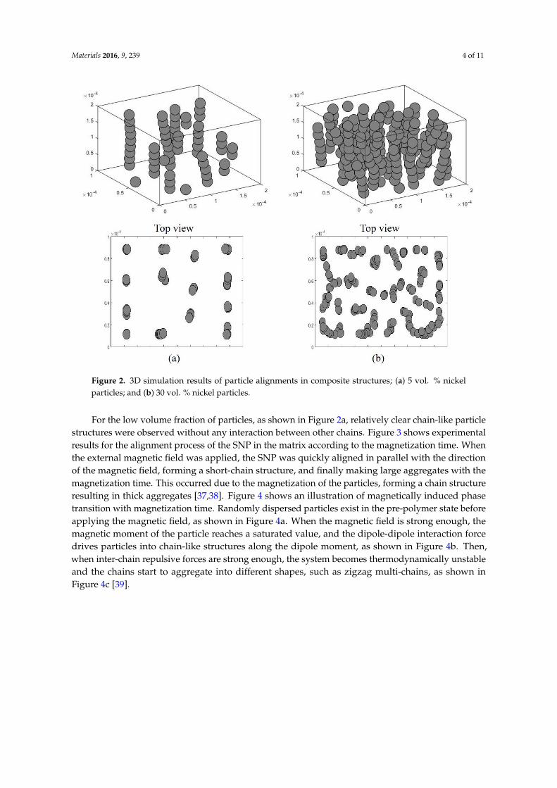
Figure 5. OM images of SNP in the matrix at different concentration; (a) 10 vol. % SNP withoutmagnetic field; (b) 10 vol. % SNP under magnetic field; (c) 20 vol. % SNP under magnetic field; and (d)30 vol. % SNP under magnetic field.
Now, we investigated the influence of SNP coalescence on the mechanical properties of theSNP/PDMS composites. Figure 6a shows three representative stress-strain curves of the SNP/PDMScomposite samples with different SNP concentrations from experimental measurements. In general,pure PDMS cured at a high temperature ruptures at a lower tensile strain than that cured at roomtemperature [40]. When the SNP concentration was low (10 vol. % of SNP), the SNP/PDMS compositeclearly showed anisotropy in the stress-strain curve. In our results, while the composite perpendicularto the magnetic field showed a similar stress-strain characteristic to that of pure PDMS, the compositeparallel to the magnetic field showed a higher tensile stress at a less tensile strain. However, when theSNP concentration was significantly increased (40 vol. % of SNP), the composite showed an almostisotropic behavior regardless of the direction of the applied magnetic field, as shown in Figure 6b.Table 1 summarizes the averaged maximum tensile strengths and strains of five SNP/PDMS compositesamples with varied SNP volume fractions. It was observed that the maximum tensile strain ofSNP/PDMS composites dramatically decreased with increased SNP volume fractions. Although theSNP/PDMS composite samples exhibited lower stretchability than pure PDMS, all four samples wereable to stretch more than 10% of their original lengths, which confirmed that SNP/PDMS compositesare suitable for detecting strain changes of infrastructures for structural health monitoring.

Materials 2016, 9, 239 7 of 11
Materials 2016, 9, 239 6 of 10
Now, we investigated the influence of SNP coalescence on the mechanical properties of the
SNP/PDMS composites. Figure 6a shows three representative stress-strain curves of the SNP/PDMS
composite samples with different SNP concentrations from experimental measurements. In general,
pure PDMS cured at a high temperature ruptures at a lower tensile strain than that cured at room
temperature [40]. When the SNP concentration was low (10 vol.% of SNP), the SNP/PDMS
composite clearly showed anisotropy in the stress-strain curve. In our results, while the composite
perpendicular to the magnetic field showed a similar stress-strain characteristic to that of pure
PDMS, the composite parallel to the magnetic field showed a higher tensile stress at a less tensile
strain. However, when the SNP concentration was significantly increased (40 vol.% of SNP), the
composite showed an almost isotropic behavior regardless of the direction of the applied magnetic
field, as shown in Figure 6b. Table 1 summarizes the averaged maximum tensile strengths and
strains of five SNP/PDMS composite samples with varied SNP volume fractions. It was observed
that the maximum tensile strain of SNP/PDMS composites dramatically decreased with increased
SNP volume fractions. Although the SNP/PDMS composite samples exhibited lower stretchability
than pure PDMS, all four samples were able to stretch more than 10% of their original lengths, which
confirmed that SNP/PDMS composites are suitable for detecting strain changes of infrastructures for
structural health monitoring.
Figure 6. (a) Stress-strain curve of tensile strength testing for pure PDMS and SNP/PDMS
composites; and (b) tensile stress ratio of parallel to perpendicular SNP configurations.
Table 1. Maximum tensile strength and strain of PDMS and SNP/PDMS composites.
Sample Ultimate Tensile Strength (MPa) Maximum Tensile Strain (%)
Pure PDMS 5.39 ± 1.23 144 ± 9.3
10 vol.% (Perpendicular) 5.11 ± 1.53 141 ± 10.2
10 vol.% (Parallel) 6.78 ± 1.52 127 ± 9.1
20 vol.% (Perpendicular) 6.90 ± 1.42 137 ± 11.5
20 vol.% (Parallel) 7.48 ± 1.48 120 ± 10.2
30 vol.% (Perpendicular) 6.98 ± 1.30 97 ± 9.1
30 vol.% (Parallel) 7.80 ± 1.02 89 ± 9.4
40 vol.% (Perpendicular) 8.23 ± 1.21 82 ± 8.8
40 vol.% (Parallel) 8.43 ± 1.43 79 ± 10.3
In addition to the mechanical property, the electrical property of the SNP/PDMS composites
was also characterized. Figure 7 shows the electrical conductivity of pure PDMS and SNP/PDMS
composites as a function of SNP concentrations. Table 2 summarizes the electrical conductivity of
the SNP/PDMS composites with different SNP concentrations and the directions relative to the SNP
chains. The electrical conductivity of pure PDMS is approximately 10−14 S/m, showing no change in
electrical conductivity up to 20 vol.% of SNPs regardless of the direction. This means that the SNPs
do not make a conductive network in the matrix. Based on the percolation theory, the electrical
Figure 6. (a) Stress-strain curve of tensile strength testing for pure PDMS and SNP/PDMS composites;and (b) tensile stress ratio of parallel to perpendicular SNP configurations.
Table 1. Maximum tensile strength and strain of PDMS and SNP/PDMS composites.
Sample Ultimate Tensile Strength (MPa) Maximum Tensile Strain (%)
Pure PDMS 5.39 ˘ 1.23 144 ˘ 9.310 vol. % (Perpendicular) 5.11 ˘ 1.53 141 ˘ 10.2
10 vol. % (Parallel) 6.78 ˘ 1.52 127 ˘ 9.120 vol. % (Perpendicular) 6.90 ˘ 1.42 137 ˘ 11.5
20 vol. % (Parallel) 7.48 ˘ 1.48 120 ˘ 10.230 vol. % (Perpendicular) 6.98 ˘ 1.30 97 ˘ 9.1
30 vol. % (Parallel) 7.80 ˘ 1.02 89 ˘ 9.440 vol. % (Perpendicular) 8.23 ˘ 1.21 82 ˘ 8.8
40 vol. % (Parallel) 8.43 ˘ 1.43 79 ˘ 10.3
In addition to the mechanical property, the electrical property of the SNP/PDMS compositeswas also characterized. Figure 7 shows the electrical conductivity of pure PDMS and SNP/PDMScomposites as a function of SNP concentrations. Table 2 summarizes the electrical conductivity ofthe SNP/PDMS composites with different SNP concentrations and the directions relative to the SNPchains. The electrical conductivity of pure PDMS is approximately 10´14 S/m, showing no changein electrical conductivity up to 20 vol. % of SNPs regardless of the direction. This means that theSNPs do not make a conductive network in the matrix. Based on the percolation theory, the electricalconductivity of composites is mainly dependent on the volume fraction, the size, the shape of thefillers, and the impurity [41–43]. Note that the fillers in our samples were micron-size particles withspherical shapes that affected the lower electrical conductivity. However, in this study, the SNP wasused to understand the influence of its coalescence and alignment on the anisotropy of a compositematerial and its electrical conductivity.
Rapid increases in electrical conductivity were observed with SNP/PDMS composites between15 vol. % and 20 vol. % and between 20 vol. % and 25 vol. %, in parallel with and perpendicular to themagnetic field, respectively. This phenomenon can be explained because the aligned SNP in the matrixenhanced the conductivity of the SNP network due to the alignment process under the magnetic field.However, the SNP/PDMS composites at above 35 vol. % showed similar electrical conductivities inboth directions (i.e., parallel and perpendicular) regardless of the magnetic field. This effect may beattributed to the morphology change in SNP in the matrix as observed in the experiment. The loss ofanisotropy in electrical conductivity can be explained by the loss of anisotropy in the distribution ofthe SNP in the matrix due to high particle concentration.

Materials 2016, 9, 239 8 of 11
Materials 2016, 9, 239 7 of 10
conductivity of composites is mainly dependent on the volume fraction, the size, the shape of the
fillers, and the impurity [41–43]. Note that the fillers in our samples were micron-size particles with
spherical shapes that affected the lower electrical conductivity. However, in this study, the SNP was
used to understand the influence of its coalescence and alignment on the anisotropy of a composite
material and its electrical conductivity.
Rapid increases in electrical conductivity were observed with SNP/PDMS composites between
15 vol.% and 20 vol.% and between 20 vol.% and 25 vol.%, in parallel with and perpendicular to the
magnetic field, respectively. This phenomenon can be explained because the aligned SNP in the
matrix enhanced the conductivity of the SNP network due to the alignment process under the
magnetic field. However, the SNP/PDMS composites at above 35 vol.% showed similar electrical
conductivities in both directions (i.e., parallel and perpendicular) regardless of the magnetic field.
This effect may be attributed to the morphology change in SNP in the matrix as observed in the
experiment. The loss of anisotropy in electrical conductivity can be explained by the loss of
anisotropy in the distribution of the SNP in the matrix due to high particle concentration.
Figure 7. Electrical conductivity of SNP/PDMS composite.
Table 2. Summary of electrical conductivity of SNP/PDMS composite.
Volume Fraction of
SNP (vol. %)
Electrical Conductivity (S/m) Ratio of Parallel to
Perpendicular Perpendicular Parallel
10 1.0 ± 0.04 × 10⁻¹⁴ 1.0 ± 0.05 × 10⁻¹⁴ 1.0
20 1.0 ± 0.05 × 10⁻¹⁴ 3.2 ± 0.03 × 10⁻¹⁰ 32,000.0
30 4.4 ± 0.03 × 10⁻⁹ 6.1 ± 0.04 × 10⁻⁸ 13.9
40 8.2 ± 0.07 × 10⁻⁷ 1.3 ± 0.05 × 10⁻⁶ 1.6
4. Conclusions
The main contribution of this work is to examine the influence of coalescence of nickel particles
on the mechanical and electrical properties of SNP/PDMS composites. Although conductive
polymer composites have been proposed and tested for various smart composite structures,
relatively small concentrations of filler particles have been taken into account in most cases, which
explains only the effect of the alignment of the filler particles. In our study, the alignment of SNPs in
the matrix was achieved by an external magnetic field as a function of particle concentrations up to
40 vol.%. Visual inspections and dynamic simulation confirmed the alignment of SNP and the
coalescence process with time as well as volume fractions of SNP. SNP-aligned composites showed
significant anisotropy in both mechanical and electrical properties depending on the volume
fractions. While the anisotropy material properties were clearly observed at low SNP concentrations
in terms of the mechanical and electrical properties, the material properties were changed from
Figure 7. Electrical conductivity of SNP/PDMS composite.
Table 2. Summary of electrical conductivity of SNP/PDMS composite.
Volume Fractionof SNP (vol. %)
Electrical Conductivity (S/m) Ratio of Parallel toPerpendicularPerpendicular Parallel
10 1.0 ˘ 0.04 ˆ 10´14 1.0 ˘ 0.05 ˆ 10´14 1.020 1.0 ˘ 0.05 ˆ 10´14 3.2 ˘ 0.03 ˆ 10´10 32,000.030 4.4 ˘ 0.03 ˆ 10´9 6.1 ˘ 0.04 ˆ 10´8 13.940 8.2 ˘ 0.07 ˆ 10´7 1.3 ˘ 0.05 ˆ 10´6 1.6
4. Conclusions
The main contribution of this work is to examine the influence of coalescence of nickel particleson the mechanical and electrical properties of SNP/PDMS composites. Although conductive polymercomposites have been proposed and tested for various smart composite structures, relatively smallconcentrations of filler particles have been taken into account in most cases, which explains only theeffect of the alignment of the filler particles. In our study, the alignment of SNPs in the matrix wasachieved by an external magnetic field as a function of particle concentrations up to 40 vol. %. Visualinspections and dynamic simulation confirmed the alignment of SNP and the coalescence process withtime as well as volume fractions of SNP. SNP-aligned composites showed significant anisotropy in bothmechanical and electrical properties depending on the volume fractions. While the anisotropy materialproperties were clearly observed at low SNP concentrations in terms of the mechanical and electricalproperties, the material properties were changed from anisotropic to isotropic with an increase of theSNP concentration, which is due to the magnetization of the filler particles, forming the coalescence ofnickel particles and making structural rearrangements. In addition, the effects of the alignment of SNPwere maximized at 10 vol. % and 20 vol. % SNP/PDMS composites for mechanical and for electricalanisotropies, respectively. This work provides a practical understanding of mechanical and electricalproperties of conductive polymer composites with magnetically aligned filler particles influenced bythe coalescence of particles. The SNP/PDMS composite can be used as smart composites to monitorelectrical and/or thermal properties, and thus it is important to show a stable signal response underexternal loading [44–47]. The future research will include the long-term stability of the SNP/PDMScomposite under cyclic loadings for practical applications.
Acknowledgments: This work was sponsored in part (Jang and Yin) by the National Science FoundationCMMI 1301288, and in part (Jang and Park) by Siemens (Award No.: A0155880), whose supports aregratefully acknowledged.

Materials 2016, 9, 239 9 of 11
Author Contributions: Sung-Hwan Jang designed and performed experiments, analyzed the data, and wrote thepaper. Yong-Lae Pak and Huming Yin supervised the project.
Conflicts of Interest: The authours declare no conflict of interest.
References
1. Rybak, A.; Boiteux, G.; Melis, F.; Seytre, G. Conductive polymer composites based on metallic nanofiller assmart materials for current limiting devices. Compos. Sci. Technol. 2010, 70, 410–416. [CrossRef]
2. Azar, N.S.; Pourfath, M. A Comprehensive study of transistors based on conductive polymer matrixcomposites. IEEE T. Electron. Dev. 2015, 62, 1584–1589. [CrossRef]
3. Ma, C.G.; Xi, D.Y.; Liu, M. Epoxy resin/polyetherimide/carbon black conductive polymer composites with adouble percolation structure by reaction-induced phase separation. J. Compos. Mater. 2013, 47, 1153–1160.[CrossRef]
4. Singh, J.P.; Chu, H.Y.; Abell, J.; Tripp, R.A.; Zhao, Y.P. Flexible and mechanical strain resistant large areaSERS active substrates. Nanoscale 2012, 4, 3410–3414. [CrossRef] [PubMed]
5. Gonzalez, D.M.; Korstgens, V.; Yao, Y.; Song, L.; Santoro, G.; Roth, S.V.; Müller-Buschbaum, P. Improvedpower conversion efficiency of P3HT:PCBM organic solar cells by strong spin-orbit coupling-induced delayedfluorescence. Adv. Energy Mater. 2015, 5, 1401770.
6. Kang, I.P.; Schulz, M.J.; Kim, J.H.; Shanov, V.; Shi, D.L. A carbon nanotube strain sensor for structural healthmonitoring. Smart Mater. Struct. 2006, 15, 737–748. [CrossRef]
7. Laflamme, S.; Kollosche, M.; Connor, J.J.; Kofod, G. Robust flexible capacitive surface sensor for structuralhealth monitoring applications. J. Eng. Mech. 2013, 139, 879–885. [CrossRef]
8. Jang, S.H.; Yin, H.M. Effect of aligned ferromagnetic particles on strain sensitivity of multi-walled carbonnanotube/polydimethylsiloxane sensors. Appl. Phys. Let. 2015, 106, 141903. [CrossRef]
9. Chang, P.C.; Flatau, A.; Liu, S.C. Review paper: Health monitoring of civil infrastructure. Struct. Health Monit.2003, 2, 257–267. [CrossRef]
10. Balageas, D. Introduction to Structural Health Monitoring. In Structural Health Monitoring; Balageas, D.,Fritzen, C.P., Eds.; ISTE: London, UK, 2006.
11. Choi, J.J.; Hahn, B.D.; Ryu, J.; Yoon, W.H.; Lee, B.K.; Park, D.S. Preparation and characterization ofpiezoelectric ceramic-polymer composite thick films by aerosol deposition for sensor application. Sens. Actuat.A-Phys. 2009, 153, 89–95. [CrossRef]
12. Li, J.P.; Peng, T.Z.; Fang, C. Screen-printable sol-gel ceramic carbon composite pH sensor with a receptorzeolite. Anal. Chim. Acta 2002, 455, 53–60. [CrossRef]
13. Qin, F.X.; Peng, H.X.; Tang, J.; Qin, L.C. Ferromagnetic microwires enabled polymer composites for sensingapplications. Compos. Part A-Appl. Sci. Manuf. 2010, 41, 1823–1828. [CrossRef]
14. Hu, N.; Karube, Y.; Arai, M.; Watanabe, T.; Yan, C.; Li, Y.; Liu, Y.; Fukunaga, H. Investigation on sensitivity ofa polymer/carbon nanotube composite strain sensor. Carbon 2010, 48, 680–687. [CrossRef]
15. Vemuru, S.M.; Wahi, R.; Nagarajaiah, S.; Ajayan, P.M. Strain sensing using a multiwalled carbon nanotubefilm. J. Strain. Anal. Eng. 2009, 44, 555–562. [CrossRef]
16. Kanoun, O.; Muller, C.; Benchirouf, A.; Sanli, A.; Dinh, T.N.; Al-Hamry, A.; Bu, L.; Gerlach, C.; Bouhamed, A.Flexible carbon nanotube films for high performance strain sensors. Sensors 2014, 14, 10042–10071. [CrossRef][PubMed]
17. Park, Y.L.; Chen, B.R.; Wood, R.J. Design and fabrication of soft artificial skin using embedded microchannelsand liquid conductors. IEEE Sens. J. 2012, 12, 2711–2718. [CrossRef]
18. Fassler, A.; Majidi, C. Liquid-phase metal inclusions for a conductive polymer composite. Adv. Mater. 2015,27, 1928–1932. [CrossRef] [PubMed]
19. Shin, H.S.; Ryu, J.; Majidi, C.; Park, Y.L. Enhanced performance of microfluidic soft pressure sensors withembedded solid microspheres. J. Micromech Microeng. 2016, 26, 025011. [CrossRef]
20. Chun, K.Y.; Oh, Y.; Rho, J.; Ahn, J.H.; Kim, Y.J.; Choi, H.R.; Baik, S. Highly conductive, printable andstretchable composite films of carbon nanotubes and silver. Nat. Nanotechnol. 2010, 5, 853–857. [CrossRef][PubMed]

Materials 2016, 9, 239 10 of 11
21. Yamada, T.; Hayamizu, Y.; Yamamoto, Y.; Yomogida, Y.; Izadi-Najafabadi, A.; Futaba, D.N.; Hata, K. Astretchable carbon nanotube strain sensor for human-motion detection. Nat. Nanotechnol. 2011, 6, 296–301.[CrossRef] [PubMed]
22. Yamaguchi, K.; Matsumoto, K.; Fujii, T. Magnetic-anisotropy by ferromagnetic particles alignment in amagnetic-field. J. Appl. Phys. 1990, 67, 4493–4495. [CrossRef]
23. Park, C.; Robertson, R.E. Alignment of particles by an electric field. Mat. Sci. Eng. A-Struct. 1998, 257,295–311. [CrossRef]
24. Borzsonyi, T.; Szabo, B.; Wegner, S.; Harth, K.; Torok, J.; Somfai, E.; Bien, T.; Stannarius, R. Shear-inducedalignment and dynamics of elongated granular particles. Phys. Rev. E 2012, 86, 051304.
25. Shen, X.J.; Liu, Y.; Feng, Q.P.; Xiao, H.M.; Fu, S.Y.; Friedrich, K. Preparation and characterization ofmultifunctional free-standing Ni/epoxy composite films. Express Polym. Lett. 2012, 6, 903–913. [CrossRef]
26. Zhu, L.; Xie, D.S.; Ma, J.; Shao, J.; Shen, X.Q. Fabrication of polydimethylsiloxane composites with nickelparticles and nickel fibers and study of their magnetic properties. Smart Mater. Struct. 2013, 22, 45015–45021.[CrossRef]
27. Park, B.J.; Fang, F.F.; Choi, H.J. Magnetorheology: Materials and application. Soft Matter 2010, 6, 5246–5253.[CrossRef]
28. Song, P.; Peng, Z.J.; Yue, Y.L.; Zhang, H.; Zhang, Z.; Fan, Y.C. Mechanical properties of silicone compositesreinforced with micron- and nano-sized magnetic particles. Express Polym. Lett. 2013, 7, 546–553. [CrossRef]
29. Sun, L.; Keshoju, K.; Xing, H. Magnetic field mediated nanowire alignment in liquids for nanocompositesynthesis. Nanotechnology 2008, 19, 405603. [CrossRef] [PubMed]
30. Steinert, B.W.; Dean, D.R. Magnetic field alignment and electrical properties of solution cast PET-carbonnanotube composite films. Polymer 2009, 50, 898–904. [CrossRef]
31. Song, H.; Tan, M.Y.; Walker, T.W.; Jander, A.; Dhagat, P. Planar alignment of magnetic microdisks incomposites using rotating fields. IEEE Trans. Mag. 2015, 51, 2802105.
32. Kim, K.; Kim, M.; Kim, J.; Kim, J. Magnetic filler alignment of paramagnetic Fe3O4 coated SiC/epoxycomposite for thermal conductivity improvement. Ceram. Int. 2015, 41, 12280–12287. [CrossRef]
33. Kumar, A.; Khusid, B.; Qiu, Z.Y.; Acrivos, A. New electric-field-driven mesoscale phase transitions inpolarized suspensions. Phys. Rev. Lett. 2005, 95, 258301. [CrossRef] [PubMed]
34. Jang, S.H.; Yin, H.Y. Effective electrical conductivity of carbon nanotube-polymer composites: a simplifiedmodel and its validation. Mater. Res. Express 2015, 2, 045602. [CrossRef]
35. ASTM D412. Standard Test Methods for Vulcanized Rubber and Thermoplastic Elastomers–Tension; ASTM International:West Conshohocken, PA, USA, 2013.
36. Kang, T.G.; Hulsen, M.A.; den Toonder, J.M.J.; Anderson, P.D.; Meijer, H.E.H. A direct simulation method forflows with suspended paramagnetic particles. J. Comput. Phys. 2008, 227, 4441–4458. [CrossRef]
37. Trohidou, K.N.; Kechrakos, D. Magnetization behaviour of small particle aggregates. J. Phys.: Condens. Matter.1988, 10, L255–L258. [CrossRef]
38. Chen, Y.; Guo, Y.; Batra, S.; Unsal, E.; Wang, E.; Wang, Y.; Cakmak, M. Large-scale R2R fabrication ofpiezoresistive films (Ni/PDMS) with enhanced through thickness electrical and thermal properties byapplying a magnetic field. RSC Adv. 2015, 5, 92071–92079.
39. Wang, M.S.; He, L.; Yin, Y.D. Magnetic field guided colloidal assembly. Mater. Today 2013, 16, 110–116.[CrossRef]
40. Johnston, I.D.; McCluskey, D.K.; Tan, C.K.L.; Tracey, M.C. Mechanical characterization of bulk Sylgard 184for microfluidics and microengineering. J. Micromech. Microeng. 2014, 24, 035017. [CrossRef]
41. Mitescu, C.D.; Allain, M.; Guyon, E.; Clerc, J.P. Electrical conductivity of finite-size percolation networks.J. Phys. A: Math. Gen. 1982, 15, 2523–2531. [CrossRef]
42. Karasek, L.; Meissner, B.; Asai, S.; Sumita, M. Percolation concept: polymer-filler gel formation, electricalconductivity and dynamic electrical properties of carbon-black-filled rubbers. Polym. J. 1996, 28, 121–126.[CrossRef]
43. Zhu, L.J.; Cai, W.Z.; Gu, B.Q.; Tu, S.T. Tunneling percolation model of the electrical conductivity of particulatenanocomposites. Mod. Phys. Lett. B 2009, 23, 1273–1279. [CrossRef]
44. Bruning, K.; Schneider, K.; Roth, S.V.; Heinrich, G. Kinetics of strain-induced crystallization in natural rubberstudied by WAXD: dynamic and impact tensile experiments. Macromolecules 2012, 45, 7914–7919. [CrossRef]

Materials 2016, 9, 239 11 of 11
45. Yazdani, H.; Hatami, K.; Khosravi, E.; Harper, K.; Grady, B.P. Strain-sensitive conductivity of carbonblack-filled PVC composites subjected to cyclic loading. Carbon 2014, 79, 393–405. [CrossRef]
46. Mansour, S.A. Effect of extensional cyclic strain on the mechanical and physico-mechanical properties ofPVC-NBR/graphite composites. Express Polym. Lett. 2008, 2, 836–845. [CrossRef]
47. Bhagavatheswaran, E.S.; Parsekar, M.; Das, A.; Le, H.H.; Wiessner, S.; Stockelhuber, K.W.; Schmaucks, G.;Heinrich, G. Construction of an interconnected nanostructured carbon black network: development of highlystretchable and robust elastomeric conductors. J Phys. Chem. C 2015, 119, 21723–21731.
© 2016 by the authors; licensee MDPI, Basel, Switzerland. This article is an open accessarticle distributed under the terms and conditions of the Creative Commons by Attribution(CC-BY) license (http://creativecommons.org/licenses/by/4.0/).