Computer Information Systems Computer Information Systems ...

INF523: Computer Systems Assurance
Measuring Security
http://ccss.usc.edu/523
Prof. Clifford Neuman
Lecture 23 September 2021OHE-120

Course Identification
• DSci 523– Assurance in Cyberspace
– 4.0 units
• Class meeting schedule– 1:00-4:20pm Friday
– Room: OHE-120 and Online
– Class communication• [email protected], include DSci523: in subject
1

General Course Information
• Professor office hours– Monday 12:30PM to 2:00PM
– Other times by appointment• Zoom link was sent to students
• Zoom link listed on DEN D2L Office Hours &
Announcements
– E-mail: [email protected]
2

Case Studies Phase 1
• Proposal Assignment for Case Study:– Case studies presented in two stages.
• A 10 minute presentation on the 24th of September– The presentation should identify a class of systems or a
particular system or product (e.g. The could, ApplePay, the
i-phone, Android, SE-Linux, etc)You should have sent and received approval for topic.
– Explain (though not necessarily answer) the assurance
issues that need to be met by the identified system.
– Identify the consequences of security failure in such
systems.
– Discuss where one will look to answer those questions.
• Topics will be grouped into related systems
3

Case Study Phase 2
• Students in groups will prepare a case study
presentation of approximately 30 minutes per
student.– Each student will take a section
– Questions to be addressed include:• Where is the TCB(s) in the system(s)
– How does the system utilize minimization
• Where should the TCB(s) be.
• What assurance techniques are applied
• How to improve the security of the system
• These will be presented near the end of the
semester.
4

Example Case Studies
• You can find examples of case studies by
students from previous years (posted with their
permission):– System Security Enhancements in Windows 10,
Summer 2017 Case Study, Samuel Aspiranti
– Security Enhanced LINUX, Fall 2015 Case Study -
John Bush and Heather Romero
5

INF523: Computer Systems Assurance
Microsoft SDL
http://www.csclass.info/USC/INF523/F21/
Prof. Clifford Neuman
Lecture 23 September 2021OHE-120

Microsoft Security Development Lifecycle (SDL)
• Mandated for use at Microsoft since 2004
• 7 phases:– Training
– Requirements
– Design
– Implementation
– Verification
– Release
– Response
7

Training Phase
• For all developers
• Major topics:– Common excuses for not fixing bugs
– Secure design - identify and avoid issues that can
lead to compromise (does this imply there is a
policy?)
– Threat modeling
– Secure coding
– Security testing
– Privacy best practices
8
Requirements Phase
• Establish security and privacy requirements– Based on what criteria?
• Create quality gates/bug bars– E.g., require fixing of all “critical” vulnerabilities before
release
• Perform security and privacy risk assessments– Determine need for threat modeling and security
design reviews of components
– Based on costs and regulatory requirements
9

Design Phase
• Establish design requirements– Validate all design specifications against a functional
specification
– Presumably, security functions identified in previous phase
• Perform attack surface analysis and reduction– Disable or restrict access to services
– Reduce privilege
– Layered defenses
• Use threat modeling– Microsoft STRIDE approach
– We’ll look at that in a future lecture
10

Implementation Phase
• Use approved tools– Approved compilers and linkers (and associated
options and warnings)
• Deprecate unsafe functions and APIs– Ban unsafe functions
• e.g., gets does not check bounds; use fgets instead
– Use newer header files, compilers, or code scanning
tools
• Perform static analysis– Automated tool scans code for common flaws without
executing the code
– We’ll look at this in a future lecture
11

Verification Phase
• Perform Dynamic Analysis– Run-time verification of software functionality
– Checks for memory corruption, user privilege issues, etc.
– We’ll discuss this topic in a future lecture
• Perform Fuzz Testing– Try to induce failure through malformed or random input data
• Conduct attack surface review– As in design phase, but on system basis
– Tool takes snapshot of Windows system state before and
after installation of product (http://www.microsoft.com/en-
us/download/details.aspx?id=24487)
12

Attack Surface
• Attack surface: Exposed parts of systems that may have exploitable vulnerabilities, e.g., – Open ports on outward facing web and other servers– Code that processes incoming data– Employees who can be “socially-engineered”
• Reference monitor (RM) abstraction helps– TCB shrinks attack surface– But still must consider threats to RM
• May have low-assurance components, not RM– E.g., your typical corporate IT network– Can still try to show non-bypassable, tamper-proof, and
make assurance arguments– Security mechanisms probably have vulnerabilities!
13

Release Phase
• Create an Incident Response Plan– Includes emergency contacts and maintenance plan
– For incidents with both internally developed and
licensed software
• Conduct final security review– Examine artifacts of security activities (e.g., threat
models) against quality gates/bug bars
• Certify release and archive– Attest that all security and privacy requirements met
– Archive all specs, source, binaries, SDL artifacts, etc.
14
INF523: Computer Systems Assurance
Limits of SDLOther Assessment Models
http://www.csclass.info/USC/INF523/F21/
Prof. Clifford Neuman
Lecture 310 September 2021OHE-120

Limits of Microsoft SDL
• Still little or no connection to policy– Policy is implicit, perhaps
– How do you know you have identified all (well, most)
threats and requirements?
• Does it work? (http://www.gfi.com/blog/report-most-vulnerable-operating-systems-and-applications-in-
2013/)
– Application in 2013 with the most critical flaws
discovered: Microsoft Internet Explorer
– OS in 2013 with the most critical flaws discovered:
Microsoft Windows Server 2008• Next 5: Windows 7, Vista, XP, Windows Server 2003,
Windows 8
16

Why Is Microsoft Software Still so Vulnerable?
• Different targets– TCSEC: TCB that enforces a policy
– MSDL: Any software; no policy
• Different requirements– TCSEC: Only goal is enforcing security policy
– MSDL: “Security and privacy” requirements possibly
secondary to other requirements• E.g., legacy code components and support
• Different testing– TCSEC: Think like an attacker – directed and
prioritized
– MSDL: Passive search for flaws – random, flat
17

Some Other Models
• SAFECode “Fundamental Practices for Secure
Software Development”– http://www.safecode.org/publication/SAFECode_Dev_Practices0211.pdf
– Aimed at reducing software weaknesses
• OWASP Software Assurance Maturity Model
(OpenSAMM) https://www.owasp.org/index.php/Category:Software_Assurance_Maturity_Model
– Many similarities to BSIMM – e.g., 4 domains, 12
practices
– But more prescriptive focus
• Dept. of Homeland Security “Build Security In”
initiative https://buildsecurityin.us-cert.gov/
18

NIST 800-171
• Some assessment methodologies are checklists of best practices that an organization should follow.– NIST SP 800-171: Protecting Controlled Unclassified Information
in Nonfederal Systems and Organizations • Lists 110 requirements in 14 areas (sometimes called families)
– What is being assessed – An organization, end user, their
systems (as deployed).
19

Least Privilege
Limit information
system access to the types
of transactions and
functions that authorized
users are permitted to
execute.
Unclassified
Unclassified
20

More on Authentication
Unclassified
Unclassified
21

New Models for Assessment
• There are new assessment methodologies in the works that combine the checklist of controls (e.g.NIST 800-171) with maturity assessment approaches (e.g. CMMI Capability Maturity Model Integration). – US DoD Cybersecurity Maturity Model Certification
(CMMC)• As envisioned levels correspond to the subset of controls implemented AND
the highest level of maturity achived.• 1 is Basic hygiene, perhaps 17 controls, and ad hoc security processes• Level 2 adds controls and required security processed to be documented• Level 3 adds more controls and required processes guided by policy• Level 5 reqires continuous improvement of process and sharing of data.
22

INF523: Computer System Assurance
Threat Modeling
Lecture 310 Sep 2021
Prof. Clifford Neuman

Reading for This Lecture
The following readings are linked from the class web page: (http://www.csclass.info/USC/INF523/F21/)
• Attack Trees
• A Requires/Provides Model for Computer Attacks
• Uncover Security Design Flaws Using the STRIDE Approach
• Foundations of Attack–Defense Trees
• Threat Risk Analysis for Cloud Security based on Attack-Defense Trees
24

Topics Covered in this Lecture
• Threat modeling techniques and tools– Attack Trees and Attack-Defense Trees
– Requires/Provides modeling
– Microsoft STRIDE approach and tool
25

Purpose of Threat Modeling
• Identify threats against a system – Identify deficiencies in security requirements and
design
• Identify threat countermeasures– Include, but not limited to, technical mechanisms
– May include administrative and physical controls
– Must also consider threats to the countermeasures!
• Increase assurance
• Process should be repeatable, methodical
26

Attack Trees
• Intended to be a “formal” way of modeling attacks
• “Tree-like representation of an attacker’s goal
recursively refined into conjunctive or disjunctive
sub-goals”
• Attacker’s “goal” is root of tree
• Different ways of achieving goal are leaves– Called “refinements” of the parent goal
• Initially proposed by Schneier in 1999
• Formalized by Mauw and Oostdijk in 2005 (Foundations of Attack Trees [ICISC’05],
http://www.win.tue.nl/~sjouke/publications/papers/attacktrees.pdf)
27

Attack Trees
• Schneier’s safe example:
• Mark leaves as “possible” or “impossible”.
• “Or” nodes and “and” nodes
• When is goal possible?
28

Attack Trees
• Node is “possible” if any of the “or” children
beneath it are possible, or if all of the “and”
children are possible
• Schneier’s example:
29

Attack Trees
• Any binary value can be used, not just “possible”
and “impossible”– Indicates likelihood or risk
– E.g., “special equipment” vs. “no special equipment”,
as in example:
– “easy” versus “difficult”
– “expensive” or “cheap”
– legal versus illegal
– “intrusive” versus “nonintrusive”
30

Attack Trees
• Can also use a continuous value function
• E.g., Schneier’s example:
• Estimated cost to attacker of each refinement
• Value in each node is sum of “and” leaves or
lowest value of “or” leaves– Assumes cost isimportant
factor for attacker
31

Attack Trees
• As with boolean values, continuous functions
used to indicate likelihood or risk of particular
attack
• Can combine multiple functions– E.g., “cheapest attack with the highest probability of
success”
32

Attack Tree Exercise
• Continue to fill out this attack tree
33
Steal login credentials
Find written down Phish Shoulder surf …

Attack Trees
• Knowledge and creativity needed by analysts– Think like an attacker
– All sorts of vulnerabilities in different sub-systems
– Analysts must understand all parts of the system well
• How do you determine a good value for a leaf
node?– Analyst must study presumed attackers as well
– E.g., if organized international crime, have lots of
money, expertise and little fear of jail, so what is
threshold?
• Often highly subjective
34

Attack Trees
35
https://xkcd.com/538/

Countermeasures
• Once tree “complete”, use it to identify
countermeasures
• Bring value of node below threshold to
“deactivate”– E.g., a countermeasure that makes a leaf
“impossible”
– Or that makes too expensive
• Do that for all “or” leaves or any “and” leaf to
deactivate parent
• Recurse up the tree to root
36

Attack Trees, Pros and Cons
• Pros– Conceptually simple
– Scalable
– Reusable
• Cons– Only considers attacker’s point of view
– No countermeasures in the graph• How do you show attacks on the countermeasures?
– No attacker/defender interactions
– Simple signatures or single-point exploits
– Weak or no explicit link between steps• How are they related? Ordering?
37

Attacks on Elections
Hack an
Election
Manipulate
Voters
Discourage/
Prevent VotingManipulate
Vote Tallies
Create
Distrust of
Outcome
Create
Errors in
Published
Returns
MicroTargeting
AdsDisinformation
Regarding
Incidents
Release
Unflattering
Stolen Data
Manipulate
Voter Rolls
DoS to
Shutdown
Selected
Poling
Locations
Send out
Incorrect
Poll
Locations or
Dates Subversion
of Voting
Systems
Subvert
Election
Staff
Intercept
Comms or
Transport of
Votes /
Ballots
Create
Confusion
among
Voters
Demonstrat
e Hacks and
Fraud in
Some
Districts
Disinformation
M
M
Ineligible /
Nonexistent/
Dead Voters
C
C
V
UUU
E
E
EMM M
E
E
E
E
E
E
E
MC
S S
S
S
Disrupt an
Election
S
C
VM
E
U
U
Campaign Officials Workers
Election Officials Workers
VotersMedia
Social Media / Sites / Services
Source: Clifford Neuman

Attack-Defense Trees
• Introduced by Kordy et al.
(Foundations of Attack–Defense Trees [FAST’10],
http://satoss.uni.lu/members/barbara/papers/adt.pdf)
• Includes countermeasures, so can show attacks
on countermeasures
39

Attack-Only Tree Example
40

Attack-Defense Tree Example
41
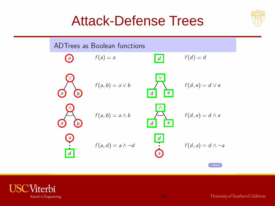
Attack-Defense Trees
42

Attack-Defense Tree Example
43
DeMorgan’s law => f = (pin /\ card) \/ (online /\ (~(key fobs \/ pin pad) \/ malware))

ADTool
• Tool for supporting the
ADTree methodology– http://satoss.uni.lu/members/piotr/adtool/
• Let’s try it out
44

A-D Trees
• Pros– Conceptually simple, but not as simple as plain trees– Scalable (assuming you don’t go hog-wild with the
countermeasures)– Reusable– Consider defender’s POV as well as attacker’s– Incorporates countermeasures and attacks on
countermeasures
• Cons– Simple signatures or single-point exploits– Weak or no explicit link between steps
• How are they related? Ordering?
45

Unified Modelling Language (UML)
• Language for specifying, visualizing,
constructing, and documenting models for
systems
• A set of notations, not a model itself
• Different diagram types:– Use case, Class, Activity, Collaboration, Sequence,
State, …
– For more info, http://www.uml-diagrams.org/
46

Example of UML Use Case Diagram
• Actors
• Associations
• Relationship
s
47

UML Component Diagrams
• Activities– Tasks that must take place in order to “fulfill
operational contract”
– Invocation of operations
– Steps in processes or entire process
– Can decompose down to atomic actions
• Components of the system– Modules, but with “required” and “provided” interfaces
• How the components interact– Component diagram shows wiring
48

Requires/Provides Model
• Templeton and Levitt, 2000
49
Single Exploits vs. Sequence
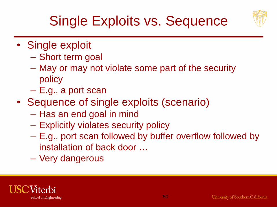
• Single exploit– Short term goal
– May or may not violate some part of the security
policy
– E.g., a port scan
• Sequence of single exploits (scenario)– Has an end goal in mind
– Explicitly violates security policy
– E.g., port scan followed by buffer overflow followed by
installation of back door …
– Very dangerous
50

Generalized Sequences of Attacks
• Port scan followed by buffer overflow followed by
installation of back door is very specific
• More general, recon followed by exploit followed by
penetration– Exploit depends on knowledge gained by recon
– Penetration depends on capability gained by exploit
• Want to abstractly model attacks based on – the requirements of the abstract components,
– the capabilities provided by the abstract components, and
– the method of composing the components into complete
attacks
51

Requires/Provides Model
• To successfully launch an attack, certain
properties must hold– These are the requires properties
• After a successful attack, a new set of properties
hold– These are the provides properties
• The attack “goal” is a property that holds after a
sequence of attack events
52
Example Attack Sequence
53
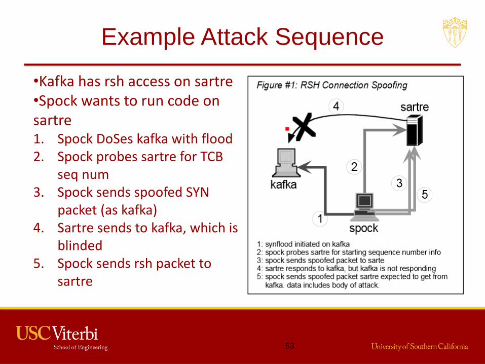
•Kafka has rsh access on sartre•Spock wants to run code on sartre1. Spock DoSes kafka with flood2. Spock probes sartre for TCB
seq num3. Spock sends spoofed SYN
packet (as kafka)4. Sartre sends to kafka, which is
blinded5. Spock sends rsh packet to
sartre

Connection Spoofing R/P
• Requires:– “Trustor” running active service (Sartre)
– Trusted partner (pretend to be trusted partner) (kafka)
– Ability to prevent trusted partner from receiving
– Ability to probe trustor for TCB sequence number
– Ability to send a forged packet
• Provides:– Ability to send data to trusted channel
– Ability to have data remotely executed
• These are general properties
• Instantiate for rsh or other protocols
54

Similarity to Attack Trees
• Goal: Get Sartre to execute commands from
untrusted host Spock
• Sub-goal: Get Sartre to believe trusted host
Kafka is sending the commands– Must prevent ACK from Sartre from reaching Kafka
– Must determine what sequence number Sartre would
use, so Spock can use that in “response” to blocked
ACK
• But different from attack trees in specifying order
55

Creating Variant Attacks
• Different events can cause the same effects
• Different orderings of events can cause the
same effects
• Want to reason in terms of the effects of an
event, not on the details of an event itself– E.g., instead of SYN-flood, the attacker on Spock
could have use a packet storm, ping-of-death, or even
physically disabled the network cable to Kafka
– Each of these would have had the same effect of
blocking Kafka from receiving ACKs from Sartre
56

Concepts and Capabilities
• Capabilities are the (generalized) information or
situation required for an attack to proceed– E.g., User login requires access, user name, password
– System requires access to password validation database
– Atomic elements of the model
– Generalized capability is template for instantiations
• Concepts map required capabilities to provided
capabilities and instantiate capabilities
• Attacks are defined as the composition of abstract
concepts
57

Inherent Implication
• Existence of a capability implies existence of
another– E.g., A prevented from sending a packet to B ➔
B is prevented from receiving a packet from A
– B is prevented from receiving a packet from A ➔
B is prevented from sending reply packet back to A
• Don’t depend on implication
• Must explicitly state concepts that define each
implication
58

JIGSAW
• Language developed to express capabilities and
concepts
• Permits mechanization– Can automatically discover ways that capabilities can
be combined into attacks
• Capability templates– Named collection of typed attribute-value pairs
• Concepts– Set of required and provided capabilities
– “With” section gives relations that must hold between
the required capabilities
59

Example Capability
capability Trusted_Partner is
service: service_type;
trustor: ip_addr_type;
trusted: ip_addr_type;
end.
60

Example Concept (abbreviated)
Concept RSH_Connection_Spoofingrequires
Trusted_Partner: TP;ForgedPacketSend: FPS;PreventPacketSend: PPS;…
withTP.service is RSH,PPS.host is TP.trusted,FPS.dst.host is TP.trustor,…
end;
61

Example Concept (abbreviated)(cont.)
Concept RSH_Connection_Spoofing, continued
providespush_channel: PSC;remote_execution: REX;
withPSC.from <- FPS.true_src; PSC.to <- FPS.dst;PSC.using <- RSH;REX.from <- FPS.true_src;…
end;
62

Power of Model
• Ordering and relationship of attack steps implicit
in that provides must precede requires– Compare to attack trees
– Capabilities essentially form edges of R/P attack graph
• Multiple events can provide equivalent capabilities
• Attack scenarios can have many variants– instantiate different events/protocols that provide same
capabilities
• Exploits can be combined in new ways to create
previously unexpected attacks– Just have to satisfy capabilities
63

Weakness of RP
• A technique for modelling multi-step abstract
attacks
• No connection to policy (same as attack trees)
64

Microsoft STRIDE Model
• Developed by Microsoft and refined over the last
10 years
• Applied to all software development activities
65

Microsoft’s Software Security Properties
Property Description
Confidentiality Data is only available to the people intended to access it.
Integrity Data and system resources are only changed in appropriate ways by appropriate people.
Availability Systems are ready when needed and perform acceptably.
Authentication The identity of users is established (or you’re willing to accept anonymous users).
Authorization Users are explicitly allowed or denied access to resources.
Nonrepudiation Users can’t perform an action and later deny performing it.
66
STRIDE
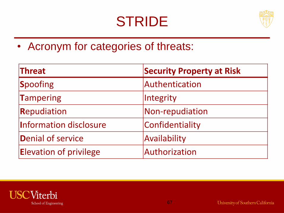
• Acronym for categories of threats:
67
Threat Security Property at Risk
Spoofing Authentication
Tampering Integrity
Repudiation Non-repudiation
Information disclosure Confidentiality
Denial of service Availability
Elevation of privilege Authorization

Meaning of Each Threat Class
• Spoofing : Impersonating something or someone else
• Tampering : Modifying data or code
• Repudiation : Claiming to have not performed an
action
• Information Disclosure : Exposing information to
someone not authorized to see it
• Denial of Service : Deny or degrade service to users
• Elevation of Privilege : Gain capabilities without
proper authorization
68

STRIDE Steps
• Decompose system into components– May need to recurse down to necessary level of detail
• Analyze each component for susceptibility to each
relevant type of threat
• Develop countermeasures until no component has
susceptibility
• Is system secure?– Maybe, but probably not
– Due to emergent properties of composition
• Does this give higher assurance?– Yes, because flaw in one component affects entire system
69

Data Flow Diagram (DFD)
• Used to graphically represent a system and its
components
• Standard set of elements:– Data flows
– Data stores
– Processes
– Interactors
• One more for threat modeling:– Trust boundaries
70

DFD Symbols
Element Shape Description
Process Any running computations or programs
Interactor A user, service, or machine that interacts with the application and is external to it – either as a data producer or consumer
Data Store Any data “at rest” on some form of storage (e.g., files, DBs, registry keys, etc.)
Data Flow Any transfer of data from one element to another (via network, pipe, RPC, etc.)
Trust Boundary Border between “trusted” and “untrusted” elements
71

Relevant Threats for Elements
72
Interactors Process Data Store
Data Flow
Spoofing x x
Tampering x x x
Repudiation x x *
Information disclosure x x x
Denial of Service x x x
Elevation of Privilege x
* Logs held in data stores are usually the mitigation against a repudiation threat. Data stores often come under attack to allow for a repudiation attack to work.

STRIDE Process
• Create DFD of system– Represent all key components
– Represent all data flows
– Identify trust boundaries
• Repeat, adding more details to the diagram if
required
• Recurse on each component as required
73

Example: First Cut
74
Data Sink!
Useless details
Data store

Example: Second Try
75
3 data flows

Analysis: Data Flow 1
• Sales to Collection
• Someone could tamper with
the data in transit
• Someone could sniff the data
• Someone could DoS the collection
service
76
Data Flow
Spoofing
Tampering x
Repudiation
Information disclosure
x
Denial of Service x
Elevation of Privilege

MS Threat Modeling Tool 2014
• Software for applying STRIDE model– Build DFD directly in program
– Automatically finds STRIDE threats
77

Mitigate Threats
• Tool has places to specify status of mitigation:– Not Started
– Needs Investigation
– Not Applicable
– Mitigated
• If you say Mitigated or Not Applicable, must
enter Justification
• Also can select priority (Low, Medium, High)– Used for the “bug bar” (ranking of threats by priority)
– E.g., see http://msdn.microsoft.com/en-
us/library/windows/desktop/cc307404.aspx
78

Controls to Mitigate Threats
• Remove vulnerable feature• “Fix” with technology, e.g.:
– Spoofing• Strong authentication
– Tampering• Strong authorization (restrict modify access)
– Repudiation• Digital signatures, timestamps
– Information Disclosure• Encryption
– Denial of Service• Packet filtering
– Elevation of Privilege• Restrict admin privilege
79
Mitigation Choices in Reality
• Redesign– Change the design to eliminate threats
– E.g., reduce elements that touch a trust boundary
• Use standard mitigations– Firewalls, validated authentication systems, …
• Use custom mitigations– If you are a gambling sort of person
• Accept risk– If you think risk is low, or too expensive to mitigate
80
Validation
• Make sure diagram is up-to-date and accurate
• Make sure you’ve captured all trust boundaries
• Enumerate all threats– The tool is an aid, but not necessarily complete
• Analyze all threats
• Mitigate all threats
81

Diagram Layers
• Context Diagram– Very high-level; entire component / product / system
• Level 1 Diagram– High level; single feature / scenario
• Level 2 Diagram– Low level; detailed sub-components of features
• Level 3 (, 4,…) Diagram– More detailed yet, if necessary
82
Combine STRIDE With Other Techniques
• Use UML instead of DFD to determine threat
targets
• Determine threats to each component using
STRIDE
• Use threat trees to help determine vulnerabilities– Each STRIDE threat is the root of a tree
• Use a risk assessment method to rank threats
83

STRIDE Pros and Cons
• STRIDE identifies security properties and threats against them– Confidentiality, Integrity, Availability, Authentication,
Authorization, Nonrepudiation– Those are effectively security policies– But where in the model are all those Windows bugs?
• And IE bugs
• Are threats comprehensive?• Patch and pray school of system design• No reference monitor concept for access policies
– Better to try to design RM, then look for threats• To isolation, completeness, verifiability
84

Topics Covered so far in this Lecture
• Threat modeling techniques and tools– Attack Trees and Attack-Defense Trees
– Requires/Provides modeling
– Microsoft STRIDE approach and tool
85

Security Requirements
• Many different definitions/approaches– E.g., Square, Clasp, STRIDE, …
• See “Security Requirements for the Rest of Us: A
Survey”, IEEE Software, January/February 2008
• Differences:– Security mechanisms or policy?
– Level of detail?
– Level of expert knowledge?
86

Factors in DeterminingSecurity Requirements
• Organizational requirements– Hopefully based on well-defined policy
• Sometimes to counter specific threats– E.g., MS STRIDE tool:
• Spoofing - Strong authentication
• Tampering - Strong authorization (restrict modify access)
• Repudiation - Digital signatures, timestamps
• Information Disclosure - Encryption
• Denial of Service - Packet filtering
• Elevation of Privilege - Restrict admin privilege
• Regulations or laws
87
Example of Reqs due to Law or Regulation
• HIPAA 45 CFR 164.312 - Technical safeguards (e)– (1) Standard: Transmission security. Implement
technical security measures to guard against unauthorized access to electronic protected health information that is being transmitted over an electronic communications network.
– (2) Implementation specifications:• (i) Integrity controls (Addressable). Implement security
measures to ensure that electronically transmitted electronic protected health information is not improperly modified without detection until disposed of.
• (ii) Encryption (Addressable). Implement a mechanism to encrypt electronic protected health information whenever deemed appropriate.
88
“Addressable” means alternative may be used if requirement is unreasonable or inappropriate.
Other Factors
• Costs
• Priority based on– Threat actors
• Goals
• Expertise
• Resources
– Likelihood of attack
– Degree of difficulty for attacker
– Value (estimated loss)
– “L”, “M”, “H” is probably best resolution possible
89
Accurate estimates of these are likely impossible!

Security Requirements Chain
• “Security objectives” (org reqs) + threats– Lead to policy
– Don’t forget subversion!
• Policy defines– what assets need protection
– what “security” means for the assets
– “Security” in terms of secrecy and integrity • Also identification/authentication, audit, authorization
• May also be availability, non-repudiation, etc.
• Policy leads to mechanisms to enforce the policy
• Which are the security requirements?
90

Policies or Mechanisms; Which are the Security Reqs?
• It depends on the organization
• If an organization doesn’t have a security policy:– Have no choice but to include policy in reqs
• If an organization has a security policy:– Reqs as in HIPAA are a good level
– But where do you specify mechanisms? Who builds them?
– Developers often have no security experience or interest
• Role of security analyst sometimes comprehensive– Specify requirements
– and enforcement mechanisms
– and verification of the enforcement mechanisms
91

Security Requirements - Mechanisms
• Policy reqs lead to mechanisms to enforce policy• Reference Monitor concept useful here
– Rather than scattershot reqs on system components– Mediate access by subjects to objects– Attempt to implement isolation, completeness,
verifiability
• Look for threats against isolation and completeness– E.g., transmitted data could be sniffed
• Mechanisms counter the threats to the RM– E.g., in network, encrypt data in transit– TNI can be helpful
92

Implementing Security Requirements
• Must trust mechanisms to enforce policy
• Structured design helps to provide assurance
• The subject of today’s lecture
93

Homework
• Due next week at start of class– Submit screen shots and other documents on D2L
• Remember, you can help each other understand
the assignment, the concepts, and the tools– But the work you turn in must be your own
• Analyze threats to a simple on-line payment
system
94

Homework Problem
• A (simple) on-line payment system runs on a web server
• Users connect using a web browser via HTTPS• Users authenticate using passwords• The server runs the payment application• The application consults a back-end
authorization database• The application connects to a back-end DB
server to record payments• The DB server stores credit card information• An attacker wants to steal credit card information
95

Homework
1. Create a plain attack tree– Use “hard” and “easy” as node values– What is the easiest route?
2. Create a corresponding A-D tree– Use ADTool (requires Java 6 or later)
• http://satoss.uni.lu/members/piotr/adtool/– Include defensive measures and attacks on defensive measures– Give the propositional interpretation of the tree
3. Write-up R/P capabilities and a concept for an attack on this system via the web connection
4. Create a STRIDE threat model– Show all processes, interactors, stores, flows, and boundaries– Use Threat Modeling Tool if you have a Windows machine– Identify threats and some countermeasures
96

Reading for Next Time (Software Design)
• D.L. Parnas, On the Criteria To Be Used in Decomposing Systems into Modules, 1972
• Daniel Hoffman, On Criteria for Module Interfaces, 1990
• Paul Karger, et. al., A VMM security kernel for the VAX architecture, 1990 – Section 3.7
• Final Evaluation Report, Gemini Trusted Network Processor, 1995 – Section 4.2
97

INF523: Computer System Assurance
Structured Design
Lecture 417 Sep 2021
Prof. Clifford Neuman

Reading for this week
• D.L. Parnas, On the Criteria To Be Used in Decomposing Systems into Modules, 1972
• Daniel Hoffman, On Criteria for Module Interfaces, 1990
• Paul Karger, et. al., A VMM security kernel for the VAX architecture, 1990 – Section 3.7
• Final Evaluation Report, Gemini Trusted Network Processor, 1995 – Section 4.2
99

“Assurance Waterfall”
100
Org. Req’s
Policy
Security Req’s
Design
Implementation Disposal
Distribution
Instal. & Config.
Maintenance
Version MgmtThreats

Structured Design
• Essential for high assurance
• Modularization and Layering
• Isolate protection-critical components; always
invoke
• Minimize complexity– May require minimizing the number of types of
objects the system supports
• What if you don’t?– System will be vulnerable to outside malware attacks
– More likely to contain residual errors in design and
implementation (or even malicious software)
101

Software Design Principles
• From IEEE Guide to the Software Engineering
Body of Knowledge, Version 3.0
• Decomposition and Modularization
• Coupling and Cohesion
• Abstraction
• Separation of interface and implementation
• Encapsulation and Information hiding
• Sufficiency, completeness, and primitiveness
102

Decomposition and Modularization
• Divide large system into smaller components– Each has well-defined interface
• Goal is to divide by functions and responsibilities
• Modularization is good– Manage complexity by using smaller parts
– System is easier to• Understand
• Develop (e.g., by a team in parallel)
• Test
• Maintain
103

Coupling and Cohesion
• Ideas developed by Larry Constantine in late
1960s
• Coupling is measure of interdependence among
modules– Amount of shared infrastructure
– Amount of coordination
– Amount of information flow
• Cohesion is measure of the degree to which
elements of a module belong together
• Want low coupling and high cohesion
104

Low Coupling; High Cohesion
105

Abstraction
• View of an object – focuses only on relevant information
– ignores the rest
• Parameterization abstracts details of data
representation by using names
• Specification abstraction hides details of
algorithm, data storage, and control by focusing
on effects/results
• Want to increase abstraction at interface of
modules
106

Separate Interface from Implementation
• Define module by specifying public interface– Parameters
– Effects
– Results
– Exceptions
• Separate from details of how module is
implemented– Algorithm
– Data structures and storage
– Control flow
107

Interface vs. Implementation
108
Caller
Interface
Implementation

Encapsulation and Information Hiding
• Grouping and packaging internal details of
modules
• Creating an abstraction
• Make the internal details inaccessible from
outside
109

Sufficiency, Completeness, and Primitiveness
• Sufficiency: Module has enough characteristics
of abstraction to be useful
• Completeness: Module implements entirety of
abstraction– Otherwise, feature likely in some other module and
high coupling results
• Primitiveness: Operations require access to
underlying representation– Want “building blocks” that can be combined into
higher-level patterns
110

Software “Architecture”
• Software Architecture in Practice (2nd edition),
by Bass, Clements, and Kazman : Architecture is– The structure or structures of the system, which
comprise• software elements,
• the externally visible properties of those elements, and
• the relationships among them.
– Architecture is concerned with the public side of
interfaces• Not details having to do solely with internal
implementation
111

Architectural Considerations
• Division of functions– Modules
– Information hiding
• Distribution of functions (in processes or systems)– Concurrency - Modules run in parallel
• Synchronization is an issue
– May be driven by underlying system architecture
• Dependencies– Which modules need to call which modules
• Interfaces (externally visible properties of elements)– Data types and methods; effects
112

Strategy for Modularization
• Manage complexity by using smaller parts
• But many possible ways of modularizing a
system
• Some ways are better than others– … which leads us to Parnas’ paper
113

KWIK Index Production System
• Accepts ordered set of lines
• Each line contains ordered set of words
• Each word contains ordered set of characters
• Lines circularly-shifted– Move first word to end making a new line
– Do for all words in each line
• Outputs a listing of all circular shifts of all lines in
alphabetical order
114

KWIK Example
• Original lines: BCF, ADE →– ADE (ambiguous if 0 shifts included)
– BCF
– CFB
– DEA
– EAD
– FBC
115

Functional Modularization
• System modeled as data flow, flow chart
• Each module implements one function in flow
• E.g., first modularization in Parnas’ paper
116
Input – Read and store data
lines
Circular Shift –Index to first char of shifts
Alphabetizer –Alphabetized
index
Output – Print all lines
Control –Sequence
other modulesStored LinesIs this system loosely or
tightly coupled?

“Information Hiding” Modularization
• System modeled on hiding implementation
decisions
• Each module hides “a secret”
117
Input Circular Shift
Alphabetizer
Output
Control
Line storageHides how lines are stored
Hides input device Hides how circ shifted lines are stored. Creates abstraction of storing all shifted lines
Hides algorithm(?)
Hides output device

Information Hiding and Abstractions
• Module creates abstraction
• Examples:– Abstract data types: Users operate on the data
without knowing its representation
– GUI creation environments: Users construct GUIs
without knowing details of how to display• E.g., X-Windows, MS VB
– Protocols: Users send and receive data without
knowing details of channel operation
– Methods: Users invoke methods without knowing
class’s algorithms
118

An Advantage of Information Hiding
• Can metaphorically “lift” the interface and slide a
new implementation under it– Take advantage of new technology but disrupt only
one module
• Choose modules based on design decisions that
are likely to change– Make that the hidden “secret”
119

“Secrets” and Changes
Secret Typical Change
How to monitor a sensor New type (more reliable, higher resolution, etc.) of sensor
How to control a device New type (faster, larger, etc.) of device
Platform characteristics New processor, multiprocessor, more memory, different chipset
How to control a display Reorganization of user interface
How to exchange data Protocol change
Database physical structure Fields added or changed, optimized storage
Algorithm Different time-space tradeoff, greater accuracy
120
Courtesy David Weiss, Iowa State Uni.

Differences between Approaches
• Different in way work is divided
• Different in interfaces
• Different in maintainability when changes made– If method or format of line storage changes
• Approach 1: EVERY module must change
• Approach 2: Only “line storage” module must change
– If change method or timing of circular shift• Approach 1: Circular shift and Alphabetizer modules change
• Approach 2: Only Circular shift module must change
– If change method or timing of alphabetization• Approach 1: Alphabetizer and output modules change
• Approach 2: Only Alphabetizer module must change
121

Reasonable Conclusion
• Decompose a system into modules using
information hiding – General criterion: each module hides design decision
from rest of system (esp. likely-to-change decision)
• DON’T decompose by function– E.g., using a flow chart or DFD
• But don’t over-modularize!– E.g., if need same data structures, put in same
module
122

Parnas’ Specific Criteria
• Data structure and accessing/modifying
procedures
• Sequence of preparation steps to call routine
and routine itself
• Control blocks– e.g., structure of actual records in a queue; Process
Control Block in OS
• Character codes, alphabetic orderings, etc.
• Sequencing – the order things are done
123

Layering
• Second modularization method (by hiding) is
layered
124
Input Circular Shift
Alphabetizer
Output
Control
Line storage
Hierarchical Structure
• Layering – Hierarchy of layers
• Partial ordering of “uses” or “depends on”
• Lower layers provide abstract machines/data
types– E.g., Line storage provides abstract original lines
– Circular shifter provides abstraction of all shifted lines
• Permits simplification of higher layers
• Lower layers provide usable basis for new system
• But note: Hierarchical layers and good
modularization are independent properties– Information hiding does not guarantee layering
125

Example of Layering
126
User Programs
Services
OS/File System 1
DAC
MAC
OS/File System 2
TCB Boundary

Layering in an OS
• External device characteristics– E.g., keyboard/display I/O
• External system characteristics– E.g., network communications protocols
• Resource allocation– E.g., process and thread management– Process scheduling– Memory management
• Janson developed idea of levels of abstraction in security kernel design (MIT Dissertation, 1976)– Used in VAX security kernel and GTNP– Each layer implements abstraction in part by calling lower
layers
127

VAX Security Kernel
• VMM that runs on VAX processors
• Creates isolated virtual VAX processors– VMs run VMS or Ultrix (Unix variant) OSes
• Security labels (simplified):– Subjects: VMs – Each has an access class
– Objects: Virtual disks – Access classes and ACLs
• Two-layer scheduler for performance (Reed, MIT):– Level 1: Small set of processes, per-process DBs all in
memory
– Level 2: User processes, require bringing per-process
DBs from disk to load in Level 1 process
128
Example OS layering: VAX Security Kernel
129
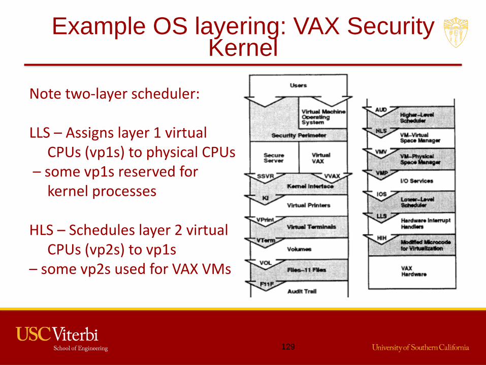
Note two-layer scheduler:
LLS – Assigns layer 1 virtual CPUs (vp1s) to physical CPUs
– some vp1s reserved for kernel processes
HLS – Schedules layer 2 virtual CPUs (vp2s) to vp1s
– some vp2s used for VAX VMs

Example OS Layering: GEMSOS
• Security kernel of GTNP• Note 2-level
scheduling
• ITC provides
VM abstraction
• UTC schedules
processes on
abstract VMs
• UTC doesn’t know
when VM blocks
• Where is DAC layer?
• Right! DAC outside
Ring 0 in GEMSOS
130

Rings
• Hardware rings enforce layering
• Calls only to lower layers
• Calls only to restricted entry points
• Interface must be carefully specified
• Entry points must be carefully code– E.g., to sanitize/filter/normalize inputs
– E.g., to handle violations of interface specification
131

Module Interfaces
• Public part of module
• Hides details: data structures, control
sequences, etc.
• Can metaphorically “lift” the interface and put a
new implementation under it
• Treat module as “black box”
132

Module Interface Specification
• Module interface specification defines– Entry points
– Syntax
– Parameters
– Data types
– Constants
– Exceptions
– Semantics of state change• When is access call legal?
• What effect on other calls?
• Makes all assumptions explicit
133

Ideal Interface Specs
• Written before implementation, not after!
• Easy to read and maintain
• Describe how to verify (test) behavior of module– Module must conform to spec
– Spec says exact effects
– Module can do that, and only that
134

Some Benefits
• Supports partitioning of system into modules
• Defines expected behavior of module
• Permits parallel development
• Gives verification requirements– Test requirements
– Acceptance criteria
• Helps find errors
135

Example Interface Specification
136

Example Interface Specification (cont.)
137

Interface Criteria
• Consistent– Naming conventions, parameter passing, exception– People tend to skip details that look familiar, so
inconsistencies will cause problems• Essential
– Omit needless features– Don’t duplicate functions
• General– Support usage for many purposes
• Minimal (primitive)– If independent features, consider using independent calls
• Opaque– Apply information hiding– Interface should be unlikely to change when
implementation does
138

“Bad” Example
• Stack module interface
• Sg_pop sets and gets at same time
• How to examine top element w/o changing stack?
• Violation and how to fix?
• Minimality – separate into s_pop and g_top
139

Another “Bad” Example
• Character input module interface• Sg_getc removes next char from input and returns
its value• Want to check if end of token• If not end, must use s_ungetc to put char back• Violation and how to fix?• Minimality – separate into s_next and g_cur
– S_ungetc no longer needed
140

Good Example of Non-minimality
• Unix malloc call
• Allocates space and returns pointer
• Always want to do both together
• No need for separate “set” and “get” calls
141

Tradeoffs
• Generality increases number of entry points– Consistency of calls for possibly unused functions
• Minimality increases number of entry points and
number of calls to them– Primitives tend to be called more often
• Sometimes opacity must be violated due to
implementation concerns– Example of initialization call to create matrix
representation
142

“Assurance Waterfall”
143
Org. Req’s
Policy
Security Req’s
Design
Implementation Disposal
Distribution
Instal. & Config.
Maintenance
Version MgmtThreats