Inert gas thrusters - NASA · Inert gases, particularly argon and xenon, are of interest as...
83
NASA CR-135226 INERT GAS THRUSTERS PREPARED FOR LEWIS RESEARCH CENTER NATIONAL AERONAUTICS AND SPACE ADMINISTRATION GRANT NSG 3011 Annual Report July 1977 Harold R. Kaufman Department of Mechanical Engineering Colorado State University Fort Collins, Colorado https://ntrs.nasa.gov/search.jsp?R=19780011255 2020-01-11T16:43:00+00:00Z
Transcript of Inert gas thrusters - NASA · Inert gases, particularly argon and xenon, are of interest as...

NASA CR-135226
INERT GAS THRUSTERS
PREPARED FOR
LEWIS RESEARCH CENTER
NATIONAL AERONAUTICS AND SPACE ADMINISTRATION
GRANT NSG 3011
Annual Report
July 1977
Harold R. Kaufman
Department of Mechanical Engineering Colorado State University
Fort Collins, Colorado
https://ntrs.nasa.gov/search.jsp?R=19780011255 2020-01-11T16:43:00+00:00Z
TECH LIBRARY KAFB, NM
1. Report No,
CR-135226-_._ .. .
4. Title and Subtitle
INERT GAS THRUSTERS (U)
7. Author(s1 Harold R. Kaufman
9. Performing Organization Name and Address
Department of Mechanical Engineering Colorado State University Fort Collins, Colorado 80523
12. Sponsoring Agency Name and Address
National Aeronautics and Space Administratior Washington, D.C. 20546
15. Supplementary Notes
Grant Manager, Vincent K. Rawlin NASA Lewis Research Center Cleveland, Ohio 44135
16. Abstract
5. Report Date July 1977
6. Performing Organization Code
8. Performing Organization Report No.
~ _ _ 10. Work Unit No. '
11. Contract or Grant No. NSG 3011
13. Type of Report and Period Covered Contractor report
1 Aug. 1976 - 30 July 1977 14. Sponsoring Agency Code
Inert gases, particularly argon and xenon, are of interest as possible alternatives to the usual electric thruster propellants of mercury and cesium. Advances in discharge-
chamber technology have been covered in a separate publication (NASA CR-135101). Hollow
cathode data were obtained for a wide range of operating conditions. Some test conditions
gave plasma coupling voltages at or below the sputtering threshold, hence should permit long operating lifetimes. All observations of hollow cathode operation were consistent
with a single theory of operation, in which a significant amount of the total electron
emission is from localized areas within the orifice. This mode of emission is also
supported by scanning electron microscope photographs that indicate local temperatures at
or near the melting temperature of the tungsten tip. Experimental hollow cathode per
formance was correlated for two orifice diameters, three inert gas propellants, and a
range of flow rates for each propellant. The degree of correlation obtained was excellent
considering the preliminary nature of this correlation study. The basic theory for the
production of doubly ionized argon and xenon has been completed. Experimental measure
ments of the doubly ionized fraction agree with theory within about +20 percent. High voltage isolators were studied for the propellant feed line. The breakdown voltage per segment ranged from 300 to over 500 V with argon.
-17. Key Words (Suggested by Author(s))
Electric Propulsion Ion Beams Ion Sources
19. Security Classif. (of this report)
Unclassified
18. Distribution Statement
Unclassified-Unlimited
I I
~
20. Security Classif. (of this page) 21. No. of Pages 22. Price'
Unclassified
' For sale by the National Technical Information Service, Springfield, Virginia 22161

TABLE OF CONTENTS
I INTRODUCTION .
I1 HOLLOW CATHODE . BACKGROUND . APPARATUS AND PROCEDURE . EXPERIMENTAL RESULTS .
I n t e r n a l E m i t t e r H o l l o w C a t h o d e .
C o n v e n t i o n a l H o l l o w C a t h o d e .
Plasma C o u p l i n g V o l t a g e . . O p e r a t i n g Mode and E l e c t r o n E m i s s i o n
SEM Photographs.
HOLLOW CATHODE PERFORMANCE CORRELATION
111 ARGON-XENON DISCHARGE CHAMBER MODEL . FOR THE PRODUCTION O F DOURLY CHARGED IONS .
THEORY . MODEL V E R I F I C A T I O N . CONCLUSION .
I V PROPELLANT ISOLATOR.
V CONCLUDING REMARKS .
REFERENCES .
1
2
2
3
10
10
15
22
2 8
34
40
46
46
59
64
65
70
72
ii

LIST OF FIGURES
Figure I 2- 1
2-2
2- 3
2-4
2-5
2-6
2-7
2-8
2-9
2-10
2-11
2-12
2-13
2-14
2-15
2-16
2-17
2-18
2-19
2-20
Hollow cathode types used in investigation . Electrical block diagram . Internal emitter hollow cathode in the neutralizer configuration
Effect of propellant flow rate changes for an internal emitter hollow cathode with a stainless steel disk anode . Effect of propellant flow rate changes for an internal emitter hollow cathode in the neutralizer configuration . Comparison of internal emitter hollow cathode performance as neutralizer and in 15-cm thruster simulator . Effect of propellant flow changes for a conventional hollow cathode with a stainless steel disk anode . Comparison of bell-jar and neutralizer performance for a conventional hollow cathode.
Effect of keeper current for a conventional hollow cathode operated as a neutralizer . Conventional hollow cathode performance and tip temperatures. Constant cathode heater power. . Conventional hollow cathode with a heat radiation fin. Tip temperature held nearly constant . Effect of propellant flow rate on neutralizer performance of a conventional hollow cathode . Comparison of facility coupling voltage with plasma coupling voltage. Neutralizer configuration with argon propellant.
Comparison of facility coupling voltage with plasma coupling voltage. Neutralizer configuration with krypton propellant .
Page
. 4
. 6
. 9
. 11
. 1 3
. 1 4
. 1 6
. 17
. 1 9
. 20
. 2 1
. 23
. 25
. 26
Comparison of anode coupling voltage with plasma coupling voltage. Disk anode configuration in bell jar with krypton propellant . . 27
Comparison of plasma coupling voltages for bell jar and neutralizer configurations. Krypton propellant . . 29
Characteristics of spot and plume modes of operation with mercury propellant . . 3 1
Cathode orifice before operation. . . 35
Cathode orifice after operation . . 37
Description of hollow cathode performance using the voltage parameter, V /ai, and the emission parameter, a!,d2 . 44
C e l
iii

Figure Page
3-1 Primary rate factor P+ for argon as a function of primary electron energy . 0 . 48
3-2 Primary rate factor P+ for xenon as a function of primary electron energy . 0 . 49
3-3 Maxwellian rate factor Q* for argon as a function of0Maxwellian electron temperature . . 50
3-4 Maxwellian rate factor Q+ for xenon as a function of 0MaxwelPian electron temperature . . 51
3-5 Primary rate factor P: for argon as a function of primary electron energy . . 53
3-6 Primary rate factor PY for xenon as a function of primary electron energy . . 54
3-7 Primary rate factor P* for argon as a function of 0primary electron energy . . 55
3-8 Primary rate factor P++ for xenon as a function of 0primary electron energy . . 56
3-9 Maxwellian rate factor QF for argon a3 a function of Maxwellian electron temperature . . 57
fl3-10 Maxwellian rate factor Q+ for xenon as a function of Maxwelfian electron temperature . . 58
3-11 Maxwellian rate factor Q++ for argon as a function of 0Maxwellian electron temperature . . 60
3-12 Maxwellian rate factor Q+I- for xenon as a function of 0MaxwelPian electron temperatures. . 61
3-13 Double-to-single ion density ratio. Correlation between theory and experiment . . 63
4-1 Inert gas propellant feed between isolator and thruster . . 66
4-2 Isolator configurations tested . . 67
4-3 Breakdown voltages per isolator segment, with thruster operating. 68
iv

I - INTRODUCTION.~~ .~
The use of i n e r t gases i n e lec t r ic t h r u s t e r s w a s s t u d i e d i n t h i s in
v e s t i g a t i o n . Of t h e i n e r t gases , t h e one whose phys ica l c h a r a c t e r i s t i c s are
most s u i t e d t o space propuls ion is xenon. High atomic weight and ease of
s t o r a g e w i t h low tankage f r a c t i o n are t h e major f a c t o r s i n t h i s choice.
Argon is a more economical a l t e r n a t i v e f o r space propuls ion i f a l a r g e
amount of p rope l l an t is r equ i r ed ( so t h a t cryogenic s t o r a g e is p r a c t i c a l )
and r e a d i l y a v a i l a b l e e l e c t r i c power makes e f f i c i e n c y (and hence atomic
weight) less important . Argon i s a l s o t h e p r e f e r r e d p rope l l an t f o r t h e
s p u t t e r e t c h i n g and d e p o s i t i o n a p p l i c a t i o n s of t h r u s t e r technology. Per
formance wi th argon i s a l a r g e r depa r tu re from t h e usua l t h r u s t e r performance
wi th mercury o r cesium, hence argon w a s emphasized over xenon. I n e r t gases
o t h e r than argon o r xenon were a l s o used t o o b t a i n b e t t e r i n s i g h t i n t o
va r ious phys ica l p rocesses .
The major e f f o r t s of t h i s i n v e s t i g a t i o n w e r e on t h e d i scha rge chamber,
t h e hollow cathode, and t h e doubly charged i o n model. There w a s a smaller
e f f o r t on t h e i s o l a t o r . The advances i n discharge-chamber technology have
been included i n a r e c e n t p u b l i c a t i o n on mul t ipo le gas t h r u s t e r design’ and
w i l l no t be repea ted here . The advances i n t h e o t h e r areas are included
h e r e i n , w i t h a s e c t i o n devoted t o each area. S I ( r a t i o n a l i z e d mks) u n i t s
are used i n t h i s r e p o r t un le s s o therwise ind ica t ed .

2
I1 - HOLLOW CATHODE
by Larry A. Rehn
BACKGROUND
The major o b j e c t i v e of t h i s s tudy w a s t o g a i n a g r e a t e r understanding
of t h e theory and o p e r a t i o n of i ne r t -gas hollow cathodes, and thereby
f a c i l i t a t e t h e achievement of long o p e r a t i n g l i f e t i m e s . A secondary
o b j e c t i v e w a s ease and r e l i a b i l i t y of s t a r t i n g . Both argon and xenon w e r e
of i n t e r e s t f o r p o s s i b l e f u t u r e missions, a l though argon w a s emphasized be
cause i t r e p r e s e n t s a g r e a t e r d e p a r t u r e from t h e u s u a l t h r u s t e r p r o p e l l a n t s
of cesium and mercury. Other i ne r t -gas p r o p e l l a n t s w e r e a l s o used t o g i v e
a d d i t i o n a l i n s i g h t i n t o hollow cathode ope ra t ion .
During t h e previous support per iod of t h i s g r a n t t h e hollow cathode
conf igu ra t ion cons i s t ed of a thermionic emitter i n s i d e a cathode chamber
1of s e v e r a l cen t ime te r s diameter . Such an i n t e r n a l emitter permit ted
r ep roduc ib le emission . c h a r a c t e r i s t i c s without t h e coa t ing and cond i t ion ing
problems of barium s t ron t ium oxides . An i n t e r n a l emitter a l s o f a c i l i t a t e d
s t a r t i n g without high v o l t a g e , and should have a longer l i f e t i m e i n s i d e
a hollow cathode than exposed t o t h e ion-chamber d i scha rge . The u s e of
a b i a s vo l t age between t h e i n t e r n a l emitter and t h e cathode chamber was
found t o extend t h e o p e r a t i n g range and e l i m i n a t e plasma f l u c t u a t i o n s , as
w e l l as f a c i l i t a t e r e l i a b l e s t a r t i n g .
The l i f e t i m e l i m i t a t i o n f o r a hollow cathode r e s u l t s from t h e e ros ion
caused by ions from t h e surrounding plasma f a l l i n g back on t h e o r i f i c e
region. Because of t h i s e r o s i o n problem, improvements i n hollow-cathode
performance have been d i r e c t e d a t e i t h e r a reduced c.oupling vo l t age f o r
a given emission or an increased emission f o r a given coupling v o l t a g e .

3
For long l i f e t i m e s , t h e coupl ing v o l t a g e should be low enough t o reduce
t h e energy of t h e bombarding i o n s below t h e th re sho ld va lue . For tungsten,
t h e th re sho ld energy ranges from about 25 t o 35 e V f o r neon, argon, krypton,
xenon, and mercury i o n s , w i th an u n c e r t a i n t y of perhaps 5 eV f o r d a t a w i t h
any one of t h e s e ions . 233
During t h i s last yea r , argon n e u t r a l i z e r tests wi th a n ope ra t ing
t h r u s t e r were conducted f i r s t by Sovey4 and l a t e r as p a r t of t h i s g r a n t
a c t i v i t y . These tests gave c o n s i s t e n t l y lower coupling v o l t a g e s (hence
longe r expected l i f e t i m e s ) than had been obtained i n b e l l j a r tests. Th i s
r e s u l t w a s unexpected i n t h a t t h e b e l l jar tests had been conducted with
c o n f i g u r a t i o n s t h a t had given an accep tab le s imulat ion of t h r u s t e r ope ra t ion
wi th mercury p r o p e l l a n t . The r e s o l u t i o n and understanding of t h e d i f f e r e n c e s
between b e l l j a r and ope ra t ing t h r u s t e r tests w a s a major a s p e c t of t h e
hollow cathode work du r ing t h i s l a s t year . I n a d d i t i o n t o tes ts i n both
b e l l j a r and t h r u s t e r environments, t h e two cathode types shown i n F ig . 2-1
w e r e i n v e s t i g a t e d . The conventional hollow cathode type (Fig. 2-1 ( a ) ) i s
s imi l a r t o c o n f i g u r a t i o n s used f o r many y e a r s w i t h mercury p r o p e l l a n t , while
t h e i n t e r n a l emi t t e r t ype w a s explored du r ing t h e previous support period
of t h i s g r a n t . A s t h e d i f f e r e n c e s between b e l l j a r and t h r u s t e r ope ra t ion
became b e t t e r understood, t h e d i f f e r e n c e s i n t h e two environments were found
t o be more important than the d i f f e r e n c e s i n t h e two cathode types . The
emphasis t h e r e f o r e s h i f t e d t o t h e convent ional cathode type , which i s more
s u i t e d t o f l i g h t a p p l i c a t i o n s .
APPARATUS AND PROCEDURE
The convent ional hollow cathodes t h a t were t e s t e d (F ig . 2-1 ( a ) ) w e r e
a l l f a b r i c a t e d of 6.35-mm diameter tantalum tubing wi th a matching t i p of
1-mm t h i c k t h o r i a t e d tungsten. Ten-ampere swaged h e a t e r w i r e w a s wrapped

Removable Tan t a I um
Propellant Tube
4
Ta ntalum Tube -
(a)
A C
fnsu lat ion \\
\ Thor iated
insert \Heater coils Tungsten Tip
Conventional Hollow Cathode
Stainless Steel Tube
Removable Tant a Ium Plate
Propellant Feed' UF Tube Tungsten FiIam ent
(b) Hollow Cathode with Internal Emitter
F i g u r e 2-1. Hollow cathode types used in investigation.

5
f o r about 1 c m nea r t h e t i p and covered wi th tantalum f o i l t o reduce t h e
r a d i a t i o n h e a t loss. The i n s e r t s w e r e c l o s e f i t t i n g porous tungs t en
c y l i n d e r s 13 nnn long w i t h 2.5 mm h o l e s through t h e a x i s . These i n s e r t s
w e r e impregnated wi th a mixture of barium and s t ron t ium oxides . A s m a l l
q u a n t i t y of t h i s oxide mixture w a s added when s t a r t i n g became d i f f i c u l t
due t o a i r e n t e r i n g t h e feed l i n e . (This problem w a s subsequently solved
by a more c a r e f u l purging technique.) Rad ia t ion f i n s , when used, w e r e 1 7 nun
i n diameter and 0.5 nun t h i c k . They w e r e made of tantalum and w e r e e l ec t ron -
beam welded t o t h e o u t s i d e edge of t h e cathode t i p . O r i f i c e s i z e s used i n
t h e convent ional hollow cathodes w e r e 0.41, 0.61, and 0.79 nnn. The f i r s t
two w e r e s t r a i g h t c y l i n d r i c a l h o l e s , wh i l e t h e l as t w a s chamfered a t t h e
downstream end.
The i n t e r n a l emitter t ype of hollow cathode w a s v a r i e d s l i g h t l y i n
diameter f o r d i f f e r e n t tests, bu t w a s always w i t h i n t h e broad optimum of
2 t o 3 cm determined i n previous tests.' The s i d e w a l l and back p l a t e of
t h i s cathode w e r e made of 1 . 5 mm t h i c k s t a i n l e s s s teel , wh i l e t h e o r i f i c e
p l a t e w a s made of 1 .0 mm tantalum. Although va r ious o r i f i c e s i z e s w e r e
s t u d i e d i n ear l ie r i n v e s t i g a t i o n s , only d a t a f o r a 2-nun o r i f i c e are in
cluded he re . The i n t e r n a l e m i t t e r w a s a loop of 0.25-nun diameter tungsten
w i r e , which had a t o t a l l e n g t h of 3 t o 4 cm.
I n i t i a l b e l l jar t e s t i n g of t h e i n t e r n a l e m i t t e r t ype of cathode
employed a 15-cm t h r u s t e r s imula to r i n an at tempt t o d u p l i c a t e t h e o p e r a t i n g
environment of t h e main cathode. (An e lec t r ica l block diagram f o r t h e
t h r u s t e r s imula to r and t h e o t h e r two b a s i c cathode conf igu ra t ions i s shown
i n Fig. 2-2.) The u s e of a s t a i n l e s s s teel sc reen 2.5 c m downstream of t h e
o r i f i c e decreased t h e cathode coupl ing v o l t a g e , bu t no t enough t o approxi
mate a c t u a l o p e r a t i n g c o n d i t i o n s f o r e i t h e r discharge-chamber o r n e u t r a l i z e r

-
6
+ Discharge DC
-- -
Heater
Emitter Bias
(a ) Bell jar thruster
Discharge
-
rCathode II IA kAnode Scr eenI Screen I Grid I II I
s mu la t or conf igurat ion
Stainless St eel Disk Anode
-Keeper
Swaged Heater Wire
Conventional Hollow Cathode w i t h Inser t
Propel lant F e e d L i n e
(b) Bell jar diode configuration.
Figure 2-2. E l e c t r i c a l block diagram.

7
Swaged Heater
I -I II
I Screen
-AIMagnet , DC +
IDischarge 1 +DC A
(c) Neutralizer configuration.
Figure 2-2. Concluded.

---
cathodes. A more complete d e s c r i p t i o n of t h i s t h r u s t e r s imula to r can
be found i n t h e preceding annual r e p o r t . 1
Later b e l l jar tests used s t a i n l e s s s teel d i s k s f o r the anode (without
t h e t h r u s t e r s imula to r ) . (See F ig . 2-2(b).) These d i s k s were 2 t o 3 cm
i n diameter and 1.6 mm t h i c k . Data are presented h e r e i n f o r anode-cathode
s e p a r a t i o n s of 4 .25 mm and 10 mm.
The n e u t r a l i z e r tests w e r e conducted i n t h e 1 . 2 - m d iameter vacuum
f a c i l i t y . (See Fig. 2-2(c).) A 15-cm mul t ipo le t h r u s t e r wi th an 8.1-cm
long chamber w a s used f o r a l l n e u t r a l i z e r tests. Th i s t h r u s t e r is descr ibed
i n t h e preceding annual r e p o r t . A beam c u r r e n t of 250 mA w a s used f o r a l l
tests. When argon w a s used as t h e p r o p e l l a n t , t h e t o t a l n e u t r a l f low t o
t h e t h r u s t e r w a s kept cons t an t a t 400 mA-equivalent. The l o c a t i o n of t h e
n e u t r a l i z e r r e l a t i v e t o t h e t h r u s t e r a c c e l e r a t o r system i s ind ica t ed i n
Fig. 2-3. Although t h e i n t e r n a l emitter type of cathode i s shown i n
Fig. 2-3, t h e o r i f i c e of t h e convent ional hollow cathode (when used) w a s
placed i n t h e l o c a t i o n shown f o r t h e o r i f i c e of t h e i n t e r n a l emitter type.
Langmuir probes w e r e used t o determine p lasma p r o p e r t i e s i n some of
t h e tests. I n t h e b e l l jar t h e probe w a s 0.64-mm diameter tantalum wire ,
exposed f o r a 2 mm l eng th . The probe l o c a t i o n i n t h e s e tests w a s midway
between t h e cathode o r i f i c e and t h e anode d i sk . The probe f o r t h e neu t r a l
i z e r tests w a s t h e s a m e , except t h a t a 1 - c m exposed l e n g t h w a s used. The
l o c a t i o n i n t h e n e u t r a l i z e r tes ts w a s a t t h e c e n t e r of t h e beam, 5 cm down
stream of t h e a c c e l e r a t o r g r i d . I n both cases t h e Debye l eng th w a s compa
r a b l e t o t h e probe d iameter , so t h a t a th ick-shea th probe a n a l y s i s w a s
5 necessary.
A h e a t e r c u r r e n t of 7 amperes w a s used f o r t h e i n t e r n a l emitter cathode.
During long runs i n t h e b e l l j a r , h e a t e r c u r r e n t ad jus tments w e r e made t o
.... -----. - --.. .. . ..-.-.. . ..... .. .

----
9
Tungsten Filament
3cm ( ID) Neutral izer
5.4 cm
I------ 1 \ \
'\\ Edge of Beam
\' \ '
15cm Thruster Chamber
Grids 4 I I I I I I
Figure 2-3. Internal emitter hollow cathode in the neutralizer configuration.

10
maintain a s t anda rd b i a s c u r r e n t when ope ra t ed i n t h e b i a s mode. This
1procedure has been desc r ibed previously. The equ iva len t emission c a l i b r a
t i o n f o r t h e convent ional hollow cathode w a s e s t a b l i s h e d w i t h a temperature
measurement, as explained la ter . An o p t i c a l pyrometer w a s used t o d e t e r
mine t h e temperature of t h e t i p nea r t h e o r i f i c e . The a b s o l u t e accuracy
of t h e s e temperature measurements w a s l i m i t e d by t h e usua l problem of
viewing through t h i c k g l a s s , b u t t h e r e p e a t a b i l i t y of measurements w a s
w i t h i n about 2 5OC.
EXPERIMENTAL RESULTS
I n t e r n a l E m i t t e r Hollow Cathode
The performance of t h e i n t e r n a l emitter hollow cathode i s shown i n
Fig. 2-4 f o r several p r o p e l l a n t flow rates. The d i s k anode w a s used f o r
t h e s e d a t a , w i th an anode-cathode spacing of 4.25 mm. The chamber diameter
of t h i s cathode w a s 2.5 c m i n diameter and a 2 mm o r i f i c e w a s used. The
cathode body w a s a t ground p o t e n t i a l i n t h e test c o n f i g u r a t i o n used. The
d i scha rge vo l t age Vd w a s t h e p o s i t i v e p o t e n t i a l of t h e anode r e l a t i v e t o
ground. (The e m i t t e r w a s heated wi th a l t e r n a t i n g c u r r e n t . " E m i t t e r p o t e n t i a l "
w a s t h e c e n t e r t a p p o t e n t i a l of t h e heater- t ransformer secondary.) This type
of cathode t h e r e f o r e had a b i a s c u r r e n t Ib ( e m i t t e r t o cathode body) i n addi
t i o n t o t h e d i scha rge c u r r e n t Id (cathode body t o anode).
A s shown i n Fig. 2-4, t h e d i scha rge v o l t a g e a t a given d i scha rge c u r r e n t
decreased wi th i n c r e a s i n g p r o p e l l a n t flow. This gene ra l performance t r end
w a s t y p i c a l of a l l hollow cathodes t e s t e d so f a r . The curve shapes tended t o
remain t h e same f o r d i f f e r e n t anode-cathode spacings, bu t s h i f t e d t o h ighe r
v o l t a g e s f o r l a r g e r spacings. The shape of t h e curves shown i n Fig. 2-4 w a s

11
2 . 5 c m Hollow Cathode - Internal Emitter 2.0 mm Orif i ce Cathode - Anode Separation 4.25" Argon - E811 Jar p = 1.3-8.4 x 10m4Torr Vb' IOV
Mass Flow, m, mA-Equiv
O 200 0 400 600
V 800 0 1000
001,,,,,,,,t
2 4 6 8 Discharge Current, I,, A
Figure 2-4. E f f e c t of p rope l l an t f low r a t e changes f o r an i n t e r n a l emi t t e r hollow cathode wi th a s t a i n l e s s s t ee l d i s k anode.

12
a l s o t y p i c a l f o r b e l l - j a r o p e r a t i o n w i t h a d i s k anode, i n t h a t t h e c u r r e n t -
v o l t a g e c h a r a c t e r i s t i c f o r a f i x e d p r o p e l l a n t f low rate could be approximated
by a s t r a i g h t l i n e over most of t h e range i n v e s t i g a t e d .
The performance of t h e i n t e r n a l emitter cathode when used as a n e u t r a l i z e r
i s shown i n Fig. 2-5.. (The c o n f i g u r a t i o n shown i n Fig. 2-3 w a s used f o r t h i s
t e s t . ) The o r i f i c e s i z e w a s 2 mm, wh i l e t h e cathode-chamber diameter w a s
3 cm. The l a t te r w a s s l i g h t l y l a r g e r than t h e 2.5 cm used f o r t h e d a t a i n
F i g . 2 4 , bu t t h i s d i f f e r e n c e w a s not enough t o g ive any s i g n i f i c a n t change i n
performance. Equipment l i m i t a t i o n s with t h e s e d a t a a l s o l i m i t e d t h e coupl ing
c u r r e n t t o about 1 ampere. The curve shapes shown, though, are t y p i c a l of
n e u t r a l i z e r tests. The coupl ing v o l t a g e a t a given coupl ing c u r r e n t decreased
w i t h inc reas ing p r o p e l l a n t flow. This decrease i n coupl ing v o l t a g e w a s
l a r g e s t between 200 and 300 mA-equivalent. A t , o r above, 300 mA-equivalent
t h e curves were somewhat "S" shaped, with a c e n t r a l p l a t e a u i n which small
changes i n coupl ing v o l t a g e gave l a r g e changes i n c u r r e n t . The "S" shaped
curves w e r e t y p i c a l f o r n e u t r a l i z e r o p e r a t i o n a t h igh p r o p e l l a n t flow rates,
and have a l s o been observed i n many previous tests w i t h t h e 15-cm t h r u s t e r
s imula to r . 1
I n t h e c o n f i g u r a t i o n used f o r t h e n e u t r a l i z e r tests t h e cathode is
b ia sed nega t ive r e l a t i v e t o t h e vacuum f a c i l i t y . The v o l t a g e d i f f e r e n c e
between t h e cathode and t h e f a c i l i t y is t h e coupl ing v o l t a g e V cf shown i n
Fig. 2-5. Because t h e i o n beam is more p o s i t i v e than t h e vacuum f a c i l i t y ,
t h e r e i s s t i l l a v o l t a g e d i f f e r e n c e between t h e cathode and t h e ion beam a t
a zero va lue of Vc f ' Nonzero coupl ing c u r r e n t s w e r e t h e r e f o r e observed a t
zero coupl ing v o l t a g e i n Fig. 2-5.
A comparison of i n t e r n a l emitter cathode performance as a n e u t r a l i z e r
and wi th t h e 1 5 - c m t h r u s t e r s imula to r i s shown i n Fig. 2-6. The o p e r a t i n g

13
3 cm Hollow Cathode - Internal Emitter 2 mm Orif i ce Neutral izer for 15-cm Thruster Argon - 1.2m Vacuum Faci l i ty p = 1 - 2 X 1 0 ' 5 T o r r 1, = 0.I A
0 0.5 1.0 Coupling Current, I , , A
Figure 2-5. E f f e c t of p r o p e l l a n t flow rate changes f o r an i n t e r n a l emitter hollow cathode i n t h e n e u t r a l i z e r conf igu ra t ion .

14
Argon Propel I ant
3 cm Neut ra l i zer ( Hollow Cathode- Internal Emitter) 2 mm Orif ice Diameter 15 cm Multipole Gas Thruster p = 2 X IO-' Torr m = 300 mA- Equivv,= IOV I h = 6.5 A
2.5 cm Hollow Cathode- Internal Emitter 2 mm O r i f i c e Bell Jar with 15cm Thruster Simulator p = 2.5 X Torr m = 500 mA- Equiv v,= IOV I,= 7 .OA
30
> 17-L
a c
I I I I I I
0 0.5 I.o Coupling Current, I,., A
Figure 2-6. Comparison of internal emitter hollow cathode performance as neutralizer and in 15-cm thruster simulator.

15
cond i t ions are n o t p r e c i s e l y t h e s a m e , b u t t h e s i m i l a r i t y of curve shape
i s c l e a r l y ev iden t . Despi te a lower p rope l l an t f low rate, t h e n e u t r a l i z e r
cathode opera ted a t 7 t o 10 V lower i n coupl ing vol tage . The coupl ing
vo l t age f o r t h e n e u t r a l i z e r w a s def ined as descr ibed above, so t h e r e f o r e
does no t i nc lude t h e p o t e n t i a l d i f f e r e n c e between t h e ion beam and t h e
vacuum f a c i l i t y . The coupl ing vo l t ages f o r n e u t r a l i z e r opera t ion , though,
approximate t h e va lues found accep tab le f o r mercury p rope l l an t n e u t r a l i z e r s ,
whi le t h e coupl ing v o l t a g e s f o r t h rus t e r - s imula to r ope ra t ion are too high
over most of t h e ope ra t ing range. The r e s u l t s shown i n Fig. 2-6 are t y p i c a l
of a l l comparisons between n e u t r a l i z e r and thrus te r -s imula tor opera t ion .
Conventional Hollow Cathode
The performance of a convent ional hollow cathode wi th a d i s k anode i s
shown i n Fig. 2-7 f o r s e v e r a l krypton flow r a t e s . S imi l a r t o t h e d a t a
shown i n ear l ie r curves , t h e vo l t age a t a cons t an t cu r ren t tends t o decrease
as p rope l l an t f low ra te i s increased . The d a t a of Fig. 2-7 w e r e a l s o s e l e c t e d
t o show double valued vo l t ages f o r a s i n g l e c u r r e n t . S i m i l a r double valued
performance has been observed s e v e r a l t i m e s and i s be l ieved t o be a real
e f f e c t r a t h e r than a d a t a e r r o r .
The d a t a f o r each mass flow rate i n F ig . 2-7 w e r e obtained a t a cons t an t
t i p temperature . The choice of a cons tan t temperature va lue w a s no t completely
a r b i t r a r y because a cathode would usua l ly o p e r a t e over on ly a l i m i t e d range.
The usua l procedure f o r s e t t i n g t i p temperature was t o use a mean va lue f o r
a range of h e a t e r powers and d ischarge c u r r e n t s . This mean va lue w a s then
he ld cons tan t by vary ing t h e h e a t e r power as d i scha rge c u r r e n t w a s va r i ed .
A comparison between b e l l - j a r and n e u t r a l i z e r ope ra t ion is shown i n
Fig. 2-8. Note t h a t t h e coupl ing vo l t age i s aga in h ighe r f o r t h e b e l l - j a r
opera t ion , d e s p i t e a h ighe r p rope l l an t f low rate f o r those da t a . S i m i l a r t o

u,
16
0.635 cm Conventional Hollow Cathode No Heat Radiation Fin; 0.41 mm Orif ice Krypton; Bel l Jar; I cm Orif ice-Anode SeparationI k = 0.3 A p = 8-24X10'5 Torr
5 0
-40> .. 9 b
.. 30
0-c U
8 0) Q,6 2 0 - Mass Flow, m, mA- Equiv Tip Temperaturec 0 .- 0 100 1 1 5 0 ° c-n 0 200 1120°c
A 300 1200 OC 10
-
I 1 I I I I I I I I00 I 2
Figure 2-7. E f f e c t of p r o p e l l a n t flow changes f o r a conventional hollow cathode with a s t a i n l e s s s t ee l d i s k anode.

17
0.635 cm Conventional Hollow Cathode 0.41 mm Orif ice Argon Ikz0.3 A
60
0
50
40 0 Discharge Voltage, v d ; Bell Jar Test; Cathode - Anode Separation = Icm; p= 2~ 1 0 ' ~
> Torr; m.400mA-Equiv L
Q) Coupling Voltage to Fac i l i ty , 00 30 V,.; 1.2m Vacuum Faci l i ty; 4- Neutral izer for 15cm Thruster; 0>
20
I O
0 0 I 2
Current, I d , I, ,A
Figure 2-8. Comparison of bell-jar and neutralizer performance for a conventional hollow cathode.

18
t h e earlier obse rva t ion wi th i n t e r n a l emitter ca thodes , a nonzero n e u t r a l i z e r
coupl ing c u r r e n t w a s observed a t zero coupl ing v o l t a g e (V c f
).
The e f f e c t of varying keeper c u r r e n t i s shown i n Fig. 2-9 f o r one pro
p e l l a n t f low rate. There i s a c l e a r t r end t o h ighe r coupl ing c u r r e n t and
lower coupl ing v o l t a g e as t h e keeper c u r r e n t is increased . Although t h i s
t r end cont inued a t h ighe r keeper c u r r e n t s , t h e keeper became very h o t ( incan
descent ) a t , o r above, 0 .4 A. A s a r e s u l t most subsequent tests w e r e conducted
a t a keeper c u r r e n t of 0.3 A .
The d a t a of Fig. 2-9 were obtained a t cons t an t h e a t e r power, wi th t h e
t i p temperature allowed t o vary. Most of t h e s a m e d a t a are shown i n Fig. 2-10,
t oge the r wi th t h e corresponding t i p temperatures . The t i p temperature
i n c r e a s e s cont inuous ly wi th inc reas ing coupl ing v o l t a g e and cu r ren t f o r
keeper c u r r e n t s of bo th 0.13 and 0.3 A. For a keeper c u r r e n t of 0.4 A,
however, t h e t i p temperature reaches a minimum between coupl ing c u r r e n t s of
0 .1 and 0.2 A . It is s i g n i f i c a n t t h a t t h e range of temperatures shown i n
F ig .2-10has been shown t o be c o n s i s t e n t wi th long i n s e r t l i f e i n s t u d i e s
conducted by Wilbur. 6
Data from another s tudy involv ing cathode temperature are shown i n
Fig. 2-11.. The cathode used had a h e a t r a d i a t i o n f i n and w a s opera ted a t
n e a r l y cons tan t t i p temperature by vary ing h e a t e r power from 0 t o 150 W.
The t i p temperature i s shown by t h e upper curve. The vol tage-cur ren t per
formance as a n e u t r a l i z e r is shown by t h e middle curve. Note t h a t t h e double
valued curve shown i s s imi l a r t o t h a t d i scussed i n connect ion wi th Fig. 2-7.
The use of a h e a t r a d i a t i o n f i n and a l a r g e r o r i f i c e permi t ted s i g n i f i c a n t l y
l a r g e r coupl ing c u r r e n t s f o r a given temperature (F ig . 2-11 ve r sus Fig. 2-10),
b u t an i n c r e a s e i n p rope l l an t f low rate i s probably a l s o requi red . The lower
curve i n F ig . 2-11 shows t h e v a r i a t i o n of h e a t f i n temperature , which roughly

19
0.635 cm Conventional Hollow Cathode 0.41 m m Orif ice Argon- 1.2 m Vacuum F a c i l i t y Neutralizer for 15 cm Thruster m = 100 mA-Equiv It,= 7.0 A p = 9 X 10'' Torr
Coupling Current, I C , A
Figure 2-9. Effect of keeper current f o r a conventional hollow cathode operated as a neutralizer.

20
0.635 cm Conventional Hollow Cathode 0.41 mm Orifice Neutralizer for 15 cm Thruster Argon - 1.2 m Vacuum Facility p = 1. I X Torr m = 100 mA-Equiv
Open Symbols = Coupling Voltage to Facility, Vcf Closed Symbols= Cathode Tip Temperature
T I I I O
I100
1090
-11080
- 1070
- l 0 6 0 y L)
- 1O5Ok L
a3 L- 1040 2 0 L 0)
-1030 E 0)
- 1020 I.-c1
'rent, t- I010 0.13 0.3 -0 . 4 1000
- 990
I . 980
Coupling Current, I,, A
Figure 2-10. Conventional hollow cathode performance and tip temperatures. Constant cathode heater power.

21
0.635 cm Conventional Hollow Cathode H e a t Radiat ion Fin; 0.79 mm Orif ice Neutra I i t e r for I5 cm Thruster Argon - 1.2 m Vacuum Faci l i ty
= 0.3 A m = 300 mA-Equiv p = l .8x10's Torr
o Coupling Voltage 0 Temperature Near O r i f i c e 0 Temperature of Edge o f Heat F in
50
-40 1000
>- r 0
0>" -Q,-30 goo<-CT Q,0 L
4- - =I 0 c> 0
L
-m20 800: .-e E n I-
0)
3 0 u
IO 1 7001
0 I I I I I I I 600 0 I 2 3 4 5 6 7 8
Coupling Current, I,, A
Figure 2-11. Conventional hollow cathode with a heat radiation fin. Tip temperature held nearly constant.
I

22
4fol lows t h e v a r i a t i o n i n h e a t e r power. Because of t h e T r e l a t i o n s h i p f o r
r a d i a t i o n , t h e h e a t f i n can p l a y an important r o l e i n ma in ta in ing t h e proper
t i p temperature. A t a coup l ing c u r r e n t of 5 A, t h e d i scha rge power (coupl ing
c u r r e n t t i m e s coupl ing v o l t a g e ) w a s 140 W. Most of t h i s power is probably
absorbed by t h e t ip--without r a i s i n g t h e t i p t o an excessive temperature.
N e u t r a l i z e r performance f o r several p r o p e l l a n t f low rates is shown i n
Fig. 2-12. A s shown b e f o r e , t h e r e i s a gene ra l t r e n d towards decreased
coupl ing v o l t a g e and inc reased c u r r e n t f o r a n i n c r e a s e i n p r o p e l l a n t flow
rate. Note t h a t t h e t i p temperatures cover a range of on ly 70°, except f o r
t h e 50 mA-equivalent flow rate. The h ighe r temperature w a s r equ i r ed f o r
s t a b l e o p e r a t i o n a t t h i s low flow rate. I n gene ra l , o p e r a t i o n a t marginal
c o n d i t i o n s r equ i r ed h i g h e r t i p temperatures.
To summarize t h e e f f e c t s of t h e d i f f e r e n t convent ional hollow cathode
c o n f i g u r a t i o n s , both h e a t f i n s and l a r g e r o r i f i c e s c l e a r l y raise t h e c u r r e n t
c a p a c i t y a t a given t i p temperature. An i n c r e a s e i n o r i f i c e diameter should
a l s o be accompanied by a n i n c r e a s e i n p r o p e l l a n t flow rate i f t h e f u l l b e n e f i t
of t h e l a r g e r o r i f i c e i s t o b e obtained. These e f f e c t s of h e a t f i n s and
o r i f i c e s i z e are a l l c o n s i s t e n t w i th previous experience us ing mercury
p r o p e l l a n t .
Plasma Coupling Voltage
Proper s imula t ion of cathode o p e r a t i o n i n a t h r u s t e r has been a recur
r e n t problem i n t h e s tudy of i ne r t -gas hollow cathodes. Such s imula t ion i s
d e s i r a b l e because b e l l - j a r o p e r a t i o n uses less manpower and equipment, hence
permits a broader i n v e s t i g a t i o n with t h e same t o t a l r e sources . The compari
sons shown i n Figs . 2-6 and 2-8, however, c l e a r l y show t h a t t h e same o r
s i m i l a r cathodes can g ive s i g n i f i c a n t l y d i f f e r e n t performance f o r d i f f e r e n t ,
test environments.

23
0.635 cm Conventional Hollow Cathode Heat Radiat ion Fin; 0.41 mm Ori f ice Neutral izer for 15 cm Thruster Argon - 1.2 m Vacuum Fac i l i ty I,= 0.3 A (0.25 A for m =5 0 mA-Equiv)
A 300 9 7 0 OC - v 400 965 OC
0 500 965 OC
1 I I I I I I I I I
Figure 2-12. Effect of propellant flow rate on neutralizer performance of a conventional hollow cathode.

24
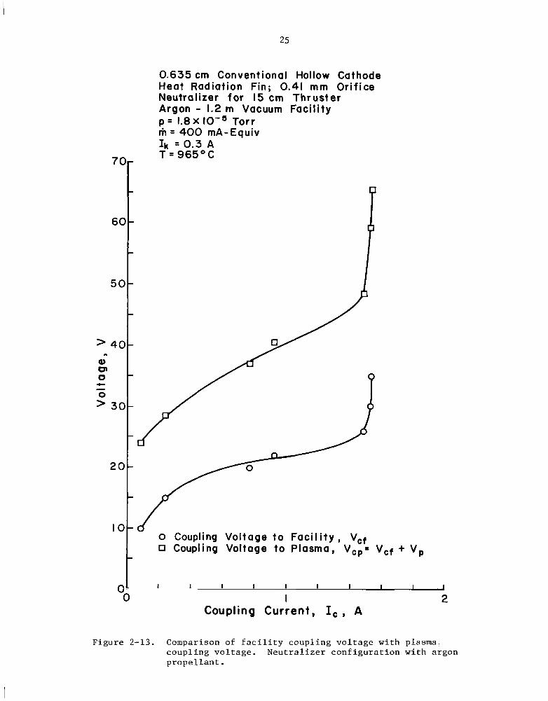
In orde r t o b e t t e r understand t h e problems of s imula t ing cathode per
formance i n a t h r u s t e r , a number of plasma probe measurements w e r e made. The
coupl ing vo l t age between a convent iona l hollow cathode and t h e vacuum f a c i l i t y
( n e u t r a l i z a t i o n conf igu ra t ion ) i s shown i n Fig. 2-13 f o r one p rope l l an t f low
rate. (The d a t a shown f o r t h i s curve are t h e same as t h e 400 mA-equivalent
d a t a shown i n F ig . 2-12.) Also shown i n Fig . 2-13 i s the coupl ing v o l t a g e
between t h e cathode and t h e plasma p o t e n t i a l a t t h e center of t h e i o n beam.
This p lasma p o t e n t i a l is p o s i t i v e r e l a t i v e t o t h e f a c i l i t y , s o t h a t t h e
coupl ing v o l t a g e t o t h e plasma is t h e sum of t h e plasma p o t e n t i a l and f a c i l i t y
coupl ing vo l t age . Both curves of coupl ing vo l t age show t h e s a m e gene ra l
shape. A s i nd ica t ed ear l ie r , t h e l a r g e r coupl ing v o l t a g e t o t h e plasma
permi ts t h e cathode t o e m i t a t zero coupl ing v o l t a g e t o t h e f a c i l i t y (F igs .
2-8 through2-10). Inasmuch as t h e c e n t e r of t h e i o n beam c l o s e t o t h e
t h r u s t e r is t h e most p o s i t i v e plasma p o t e n t i a l i n t h e beam, t h i s l o c a t i o n
can a l s o be used t o d e f i n e t h e maximum ion energy f o r cathode e ros ion . The
number of i o n s from t h i s l o c a t i o n t h a t reach t h e cathode, though, is probably
very s m a l l . Acceptable l i f e t i m e s should t h e r e f o r e be obtained wi th plasma
coupl ing v o l t a g e s somewhat above t h e s p u t t e r i n g threshold . From t h e p lasma
coupl ing vo l t ages shown, t h e n e u t r a l i z e r conf igu ra t ion used should show long
l i f e t i m e s f o r n e u t r a l i z a t i o n c u r r e n t s up t o about 1 ampere.
The same convent ional hollow cathode conf igu ra t ion as used f o r Fig.
2-13, except without a r a d i a t i o n h e a t f i n , w a s opera ted with krypton pro
p e l l a n t . In t h e n e u t r a l i z e r conf igu ra t ion , Fig. 2-14, t h e plasma and f a c i l i t y
coupl ing vo l t ages aga in show similar curve shapes. A s wi th argon, t h e plasma
coupl ing v o l t a g e is l a r g e r than t h e f a c i l i t y coupl ing vo l t age .
The same cathode as used f o r Fig. 2-14 w a s a l s o t e s t e d i n a b e l l j a r w i t h
a d i s k anode. A s shown i n Fig. 2-15, t h e plasma coupl ing v o l t a g e w a s substan
t i a l l y less than t h e d ischarge vo l t age . ( I n t h i s case t h e plasma coupl ing
25
0.635cm Conventional Hollow Cathode Heat Radiation Fin; 0.41 mm Orifice Neutralizer for 15 cm Thruster Argon - 1.2 m Vacuum Facility p = 1.8X IO-' Torr m = 400 mA-EquivIk Z O . 3 A
70- T = 965OC
-
-60
-
50- P
o Coupling Voltage to F a c i l i t y , Vcf Coupling Voltage to Plasma, V,,= Vcf
+ VP
OL I 1 1 I I I I I I I 0 I 2
Coupling Current , I , , A
Figure 2-13. Comparison of facility coupling voltage with plasma! coupling voltage. Neutralizer configuration with argon propellant.

26
0.635 cm Conventiona I Hollow Cathode No Heat Radiat ion Fin; 0.41 mm Orifice Neutralizer for 15 cm Thruster Krypton - 1.2 m Vacuum Faci l i ty I k = 0.3 A T = 1 0 5 0 ° C
70m-
Mass Flow, m, mA-Equiv - 0,. 50
0 , . 100 60- o*+ 200
A,A 300
- Open Symbols= Coupling Voltage to Facility , V,f
50 Closed Symbols= Coupling Voltage-
to Plasma, V,,
-
’40c
Q) v 0 c-
30
-
-20
-
10
-I I I I . 1 .-I I I I 1 I
OO I .;
Figure 2-14. Comparison of facility coupling voltage with plasma coupling voltage. Neutralizer configuration with krypton propellant.

2 7
0.635 cm Conventional Hollow Cathode No Heat Radiation Fin, 0.41 mm Orifice Bell Jar; Cathode - Anode Separation = I cmI,= 0.3 A Krypton
Open Symbols = Discharge Voltage, V, Closed Symbols = Coupling Voltage to PI asma, Vcp = V,
60- Mass Flow, m, mA-Equiv Tip Temperature
- 0,. 100 I I 5OoC 0,o 2 0 0 I 1 2 O 0 C O,+ 300 120O0C
50
-
-40> & >” c
s30..a# -e 0 c-
g20:10 : -
I I I I I I I I I I00 I 2
Figure 2-15. Comparison of anode coupling voltage with plasma coupling voltage. Disk anode configuration in bell jar with kryptonpropellant.
I

28
v o l t a g e i s de f ined by a Langmuir probe midway between t h e anode and cathode.)
Fu r the r , t h e curve shapes f o r t h e two coupl ing v o l t a g e s are c l e a r l y d i f f e r e n t .
The curves f o r anode coup l ing v o l t a g e are similar t o those ob ta ined w i t h
argon (Fig. 2-7). The cu rves f o r plasma coupl ing v o l t a g e , though, show t h e
extended h o r i z o n t a l shapes more c h a r a c t e r i s t i c of n e u t r a l i z e r ope ra t ion . The
small i n c r e a s e i n plasma coupl ing v o l t a g e f o r t h e 200 mA-equivalent curve a t
small d i scha rge c u r r e n t s is n o t be l i eved t o b e s i g n i f i c a n t , inasmuch as it
i s w i t h i n t h e accuracy of plasma probe d a t a .
The plasma coupl ing v o l t a g e s f o r b e l l - j a r and n e u t r a l i z e r o p e r a t i o n are
compared i n Fig. 2-16. The d i f f e r e n c e between t h e two i s S u b s t a n t i a l a t
100 mA-equivalent, and can probably b e explained as t h e d i f f e r e n c e between
spo t and plume mode. That is, s m a l l d i f f e r e n c e s i n c o n f i g u r a t i o n parameters
are known t o change t h e mode when ope ra t ion i s c l o s e t o t h e t r a n s i t i o n be
tween t h e two modes. A s a s p e c i f i c example, t h e t i p temperatures w e r e
s i g n i f i c a n t l y h i g h e r i n t h e b e l l j a r than when ope ra t ed as a n e u t r a l i z e r .
The curves f o r t h e h i g h e r p r o p e l l a n t f low rates are q u i t e s i m i l a r , wi th t h e
major d i f f e r e n c e on ly i n v o l t a g e l e v e l . The plasma p o t e n t i a l i n an ion beam
o f t e n v a r i e s by 10 o r 20 so t h a t t h e d i f f e r e n c e between t h e two curves
could poss ib ly be explained i n terms of t h e p o t e n t i a l d i f f e r e n c e between t h e
n e u t r a l i z e r l o c a t i o n and t h e c e n t e r of t h e i o n beam. It would t h e r e f o r e be
expected t h a t t h e agreement between b e l l j a r and n e u t r a l i z e r o p e r a t i o n shown
i n Fig. 2-16 would b e much c l o s e r i f t h e n e u t r a l i z e r plasma p o t e n t i a l were
measured c l o s e t o t h e n e u t r a l i z e r i n s t e a d of i n t h e c e n t e r of t h e ion beam.
Operating Mode and E lec t ron Emission
Inasmuch as hollow cathodes have been e x t e n s i v e l y t e s t e d wi th mercury
p r o p e l l a n t , t h e information obtained wi th mercury should s e r v e as a guide i n
t h e i n t e r p r e t a t i o n of i ne r t -gas test r e s u l t s . Hollow cathode tests wi th

29
0.635 cm Conventional Hollow Cathode No Heat Radiation Fin; 0.41 mm Orifice I k =0.3A Krypton
Open Symbols = Bell Jar; Cathode - Anode Separation. I cm; Vc,=Vp Closed Symbds = Neutralizer; Vcp= Vcf+ V,
Mass Flow, m, mA-Equiv
0,. 100 o,m 200o,* 300
I 2 Current, I,, I,., A
Figure 2-16.. Comparison of plasma coupling voltages for bell jar and neutralizer configurations. Krypton propellant.

30
mercury p r o p e l l a n t show a t least two d i s t i n c t modes of ope ra t ion . 8 y 9 For
high p r o p e l l a n t f low rates, small anode-cathode s e p a r a t i o n s , and h igh e l e c t r o n
emissions t h e spo t mode is obta ined . Low s t a b l e coupl ing vo l t ages and an
i n t e n s e plasma glow, o r spo t , near t h e o r i f i c e are t h e e l e c t r i c a l and v i s u a l
i n d i c a t i o n s of t h i s mode. For low p r o p e l l a n t f low r a t e s , l a r g e anode-cathode
d i s t a n c e s , and low e l e c t r o n emissions t h e plume mode is obta ined . High
coupl ing vo l t ages , o f t e n f l u c t u a t i n g , and a glowing plume downstream of t h e
o r i f i c e ( i n a d d i t i o n t o t h e glowing spo t a t t h e o r i f i c e ) a r e t h e i n d i c a t i o n s
of t h e plume mode. An in t e rmed ia t e t r a n s i t i o n mode has a l s o been observed
w i t h m e t a l l i c anodes. I n t h i s mode t h e v o l t a g e f l u c t u a t i o n s can be l a r g e
and t h e plume i s v i s i b l e only near t h e anode. Some of t h e ope ra t ing charac
terist ics w i t h spo t and plume modes a r e ind ica t ed i n F ig . 2-17, which is
reproduced from Csiky. 9
More r e c e n t plasma measurements by Wilbur'' support t h e viewpoint t h a t
t h e d i f f e r e n c e s between spo t and plume modes are a s s o c i a t e d p r imar i ly wi th
changes i n t h e plume reg ion . For e i t h e r mode, t h e average Debye l eng th i n
t h e v i c i n i t y of t h e o r i f i c e is wi th in a f a c t o r of several of 10-3 mm. The
o r i f i c e diameter i s thus equiva len t t o many Debye l e n g t h s and t h e plasma
should e a s i l y p e n e t r a t e t h e o r i f i c e i n e i t h e r mode. The e l e c t r o n dens i ty
i n t h e plume reg ion averaged about a f a c t o r of 10 lower than t h e spo t mode,
whi le t h e plasma p o t e n t i a l downstream of t h e o r i f i c e w a s l a r g e r by s e v e r a l
v o l t s i n t h e plume mode. It appears t h a t t h e ions r equ i r ed t o n e u t r a l i z e t h e
e l e c t r o n space charge come from t h e o r i f i c e i n t h e spo t mode. This i n t e r p r e
t a t i o n is supported by t h e l a c k of glow, t h e h igh e l e c t r o n dens i ty , and t h e
more uniform plasma p o t e n t i a l i n t h e plume reg ion f o r t h e spo t mode. For t h e
plume mode, t h e cha rge -neu t r a l i za t ion ions appear t o b e generated w i t h i n t h e
plume reg ion . The glowing plume and h igher o v e r a l l vo l t ages and e l e c t r o n

a"
31
c. aa 0 c 0 c [email protected] Plume M o d e 0 )
/ Either Mode,
E~n I I IF W
0 0.05 0.10 0.15 Propellant Flow Rate, A - Equiv
(a) Effect of anode-cathode distance and propellant flow rate on operating mode.
4 O r II
Mode L' I 0 spot
.-= r D Plume- I
E * O t
: O@0
I I
I 2 3 Distance from Cathode, cm
(b) Variation of plasma potential within hollow cathode efflux.
Figure 2-17. Characteristics of spot and plume modes of operation with mercury propellant.

32
e n e r g i e s support t h i s viewpoint. A l so , t h e more adverse e lectr ic f i e l d s down
stream of t h e o r i f i c e would tend t o prevent i o n s from l e a v i n g t h e o r i f i c e and
e n t e r i n g t h e plume reg ion . I n t h e s p o t mode, then, t h e cha rge -neu t r a l i z ing
i o n s are perhaps c a r r i e d from t h e o r i f i c e t o t h e plume reg ion by t h e c o l l i s i o n s
wi th n e u t r a l atoms o r molecules. In t h e plume mode, plasma mechanisms involving
e n e r g e t i c e l e c t r o n s produce t h e s e i o n s w i t h i n t h e plume reg ion . It a l s o appears
(from both Wilbur 's and previous experiments by o t h e r s ) t h a t t h e plume glow
tends t o o r i g i n a t e nea r a m e t a l l i c anode and p rogres ses upstream towards t h e
o r i f i c e wi th i n c r e a s i n g d e p a r t u r e s from spo t mode cond i t ions . The upward-
turned anode shea th (Fig. 2-17(b)) i s an obvious plume-mode mechanism f o r
gene ra t ing ions. The e l e c t r o n s a r e a c c e l e r a t e d as they approach t h e anode,
t y p i c a l l y reaching i o n i z a t i o n energy a t t h e equ i l ib r ium cond i t ion of i on
gene ra t ion . This anode mechanism has been s tud ied i n gas d i scha rges and is
11described by Cobine.
The e l e c t r o n emission from a mercury hollow cathode appears t o b e due
only i n p a r t t o t h e thermionic emission from t h e oxide coated o r impregnated * c I I L
i n s e r t . This conclusion i s supported by t e s t r e s u l t s obtained by Wilbur.
Using a c a l i b r a t e d thermionic e m i t t e r i n s i d e an otherwise convent ional hollow
cathode, t h e t o t a l cathode emission w a s two o r t h r e e t imes t h e e m i t t e r
emission. This r e s u l t , t oge the r with t h e i n t e n s e glow i n t h e o r i f i c e , c l e a r l y
i n d i c a t e s t h a t t h e i n s e r t emission is augmented by a d i scha rge mechanism
w i t h i n t h e o r i f i c e . A s tudy by Bessling13 o f f e r s a combination of high f i e l d
and thermionic emission w i t h i n t h e o r i f i c e as an a d d i t i o n a l sou rce of e l e c t r o n
emission. Fu r the r , t h i s emission w i t h i n t h e o r i f i c e i s l o c a l i z e d a t s u r f a c e
i r r e g u l a r i t i e s , v i t h t h e i n t e n s i t y of t h e c u r r e n t s s u f f i c i e n t t o cause
l o c a l i z e d melt ing i n some cases. To complete t h e p i c t u r e , t h e emi t t ed
e l e c t r o n s a l s o produce e l ec t ron - ion p a i r s w i th in t h e o r i f i c e volume. The
i ons t h a t recombine on t h e o r i f i c e w a l l s correspond t o an a d d i t i o n a l emission
of e l e c t r o n s .
To t h e e x t e n t t h a t measurements and observa t ions have been made wi th
ine r t -gas hollow ca thodes , they have gene ra l ly been i n agreement wi th t h e
preceding summary f o r mercury p rope l l an t . One a spec t where t h e agreement
has been l e s s c l e a r is t h e plume luminosi ty . I n going from spot t o plume
mode wi th argon, wi th t h e mode ind ica ted by e l e c t r i c a l measurements, no l a r g e
change w a s observed i n plume luminosi ty . The usual appearance wi th argon w a s
a v i s i b l e (but no t b r i g h t ) plume, r ega rd le s s of mode. Fewer observa t ions
w e r e made wi th krypton, b u t t h e r e w e r e s i m i l a r d i f f i c u l t i e s i n determining
t h e ope ra t ing mode from plume luminosi ty wi th t h a t p rope l l an t .
Another area of p o s s i b l e disagreement involves plasma p o t e n t i a l measure
ments. Measurements by Csiky, Fig. 2-17(b), showed t h a t spot-mode plasma
p o t e n t i a l w a s c l o s e t o t h e anode p o t e n t i a l f o r some d i s t a n c e upstream of t h e
anode. For t h e plume mode, t h e upturned sheath near t he anode w a s more
t y p i c a l . For ine r t -gas ope ra t ion , however, t h e upturned shea th a t t h e anode
w a s t y p i c a l of a l l ope ra t ion i n which probe measurements w e r e made ( see
Fig. 2-15). There have no t been enough p la sma p o t e n t i a l measurements f o r
e i t h e r mercury o r i n e r t gases t o draw f i r m conclusions, bu t i t appears
t h a t t h i s shea th e f f e c t may b e t h e cause of t h e high coupl ing vo l t ages
wi th i n e r t gases and a d i s k anode. A s descr ibed by Cobine," t h i s upturned
Larger anode areas may t h e r e f o r eshea th is enhanced by reducing anode a r e a .
reduce t h i s e f f e c t and permit b e t t e r s imula t ion of t h r u s t e r opera t ion .
A poss ib ly r e l a t e d phenomenon i s t h e adso rp t ion of mercury on s u r f a c e s
below about 300°C. 14 These adsorbed l a y e r s may o f f s e t a s m a l l anode s ize
I n e r t gases are n o twhen mercury P rope l l an t i s used wi th a d i s k anode.
adsorbed on s u r f a c e s a t normal ope ra t ing temperatures ,l5so could no t offset

an area e f f e c t i n a similar manner. More complete plasma measurements w i l l
c l e a r l y b e r equ i r ed t o r e s o l v e t h i s apparent discrepancy between mercury and
iner t -gas p r o p e l l a n t s .
SEM Photographs
Photographs w e r e t aken w i t h a scanning e l e c t r o n microscope (SEM) both
b e f o r e and af ter t e s t i n g a new cathode wi th krypton p r o p e l l a n t . The s p e c i f i c
r e s u l t s have l i m i t e d i n t e r e s t because of t h e p r o p e l l a n t , bu t t h e technique
of us ing SEM photographs of hollow cathodes has important imp l i ca t ions f o r
f u t u r e work.
A 0.61 mm o r i f i c e w a s d r i l l e d i n t h e t h o r i a t e d tungs ten t i p of a
0.635 cm convent ional hollow cathode w i t h a number 73 carb ide b i t . The
photographs shown i n Fig. 2-18 w e r e t aken be fo re t h e cathode had been t e s t e d ,
wh i l e those i n Fig. 2-19 were taken a f t e r 3% hours of ope ra t ion a t n e a r l y
cons t an t cond i t ions . The average ope ra t ing parameters w e r e a t a t i p tempera
t u r e of 95OoC, a p r o p e l l a n t flow r a t e of 300 mA-equivalent, a coupling
vo l t age t o t h e d i s k anode of 35 V , and a coupl ing vo l t age t o t h e plasma of
18 V.
Figure 2-18(a) i s reproduced h e r e i n a t a magni f ica t ion of about 108.
Metal f l a k e s from t h e d r i l l i n g can b e seen along t h e edge of t h e o r i f i c e .
The area between t h e v e r t i c a l l i n e s i n Fig. 2-18(a) is reproduced i n F ig .
2-18(b) a t a h ighe r magni f ica t ion , and a p o r t i o n of t h e l a t t e r i s reproduced
a t a s t i l l h igher magni f ica t ion i n F ig . 2-18(c). (Note t h a t t h e sample was
r o t a t e d between Figs . 2-18(a) and (b) . ) The l a r g e a r t i f a c t i n s i d e t h e o r i f i c e
(assumed t o be a tungs ten ch ip) is about 28 microns long. The s u r f a c e
s c r a t c h e s are 1 t o 2 microns wide.
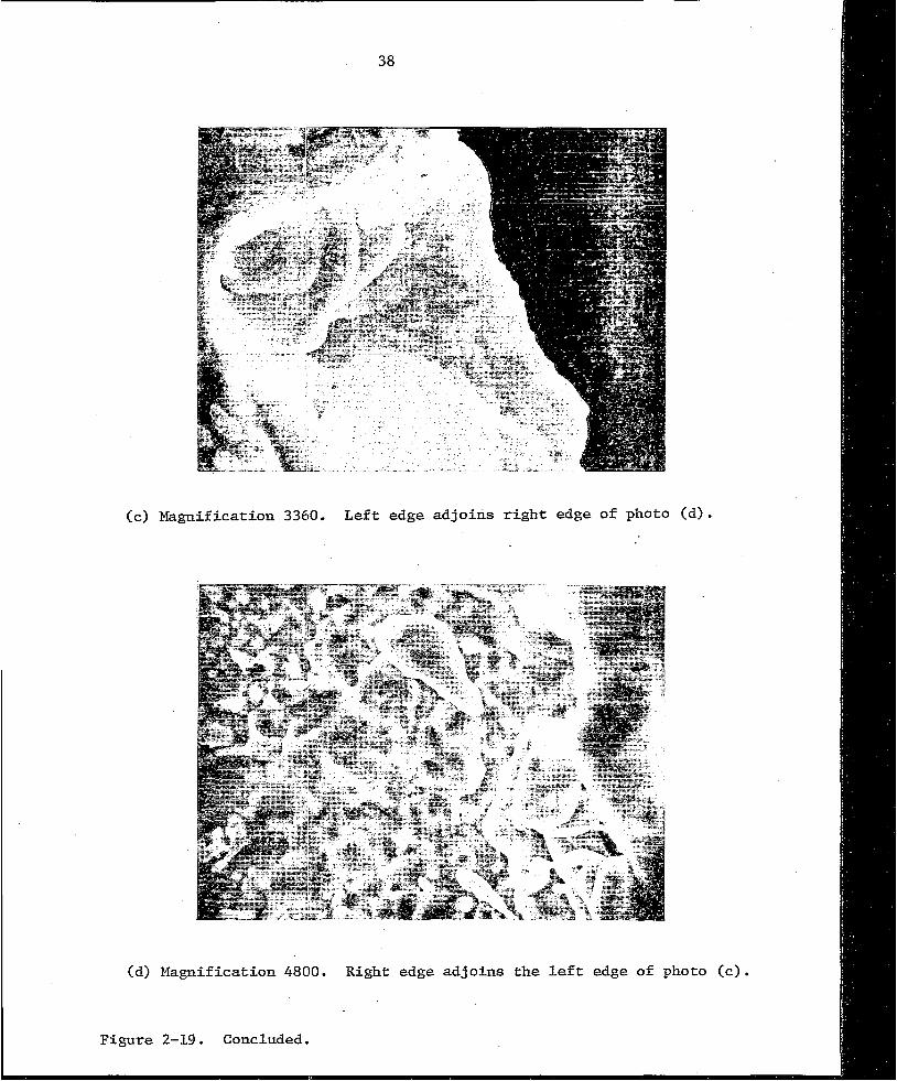
Figure 2-19(a) shows t h e e n t i r e cathode o r i f i c e a f t e r t e s t i n g . An
enlargement of t h e "8 o 'c lock" p o r t i o n of t h e o r i f i c e i n F ig . 2-19(a) i s

(a) Magnificatibn 108
(b) Magnification 300

(c) Magnification 700
Figure 2-18. Concluded.
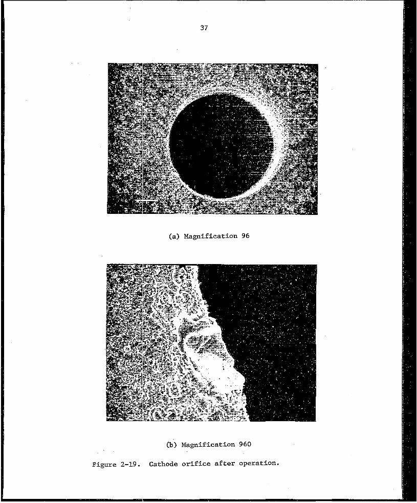
(a) Magnification 96
(b) Magnification 960
Figure 2-19. Cathode orifice after operation.
38
(c) Magnification 3360. L e f t edge ad jo ins r i g h t edge o f photo
(d) Hagnification 4800. Right edge ad jo ins t h e lef t edge of photo (c).
Figure 2-19. Concluded.

shown i n Fig. 2-19(b). This l a t t e r photograph covers about t h e s a m e area as
Fig. 2-18(b). (Both Fig. 2-18(b) and Fig. 2-19(b) are about 180 degrees from
t h e backwards "N," which i s v i s i b l e i n both Fig. 2-18(a) and Fig. 2-19(a).)
The a r t i f a c t of Fig. 2-18(b) has c l e a r l y been r e s t r u c t u r e d and only extends
some 6 microns i n t o t h e o r i f i c e a f t e r t e s t i n g . Most of t h e f i n e s u r f a c e
s c r a t c h e s have a l s o disappeared. Figure 2-19.(c) shows t h e same a r t i f a c t a t
a h ighe r magni f ica t ion , whi le Fig. 2-19(d) shows t h e area t o t h e l e f t of
Fig. 2-19(c) a t a s l i g h t l y h igher magnif icat ion. The smallest round shapes 0
shown i n F ig . 2-19(d) are 2000 t o 4000 A i n diameter .
appears t o be t h e r e s u l t of mel t ing . That i s , t h e observed changes are con
s i s t e n t wi th melted material flowing under t h e fo rces of s u r f a c e tens ion .
Some of t h e melted m a t e r i a l poss ib ly has s p a t t e r e d o r splashed onto t h e sur
rounding area (Fig. 2-19(d)). This s p a t t e r i n g , i f i t took p lace , w a s probably
t h e r e s u l t of included elements o r compounds f l a s h i n g t o vapor when t h e tungs ten
m e l t e d . The mel t ing suppor ts Bess l ing ' s theory of l o c a l i z e d i n t e n s e c u r r e n t s
and hea t ing .13 The l a r g e area-to-volume r a t i o �o r t h e o r i g i n a l shape (Fig. 2
18 (b ) ) w a s conducive t o mel t ing. A s i nd ica t ed by Bess l ing , c a l c u l a t e d tempera
t u r e s are marginal f o r t h o r i a t e d tungs ten (with mercury p r o p e l l a n t ) , so may
only be observed wi th l a r g e area-to-volume r a t i o s . It appears h igh ly l i k e l y
from t h e SEM photographs, then, t h a t l o c a l i z e d o r i f i c e temperatures can g r e a t l y
exceed t h e average t i p temperature . It a l s o a p p e a r s l i k e l y t h a t t h e s e high
l o c a l i z e d temperatures are involved i n e l e c t r o n emission.
Addi t iona l SEM photographs (not shown) w e r e taken of t h e o r i f i c e r eg ion
a t va r ious angles . The g r e a t depth of f i e l d poss ib l e wi th t h e SEM permits
such photographs t o b e used to. c o n s t r u c t an accu ra t e p r o f i l e of t h e downstream
end of t h e o r i f i c e , where most of t h e w e a r t akes p lace . This technique should
permit estimates of cathode l i f e t i m e from runs of on ly a few tens of hours.

40
HOLLOW CATaODE PERFORMANCE CORRELATION
The past development of hollow cathodes has been accomplished with mostly
trial-and-error methods. Better understanding of hollow cathode operation
would hopefully permit a more systematic approach to the development of a new
design. One approach to organizing available data is to correlate the perfor
mance with suitable parameters. Progress using this approach is described
in this section.
One parameter of apparent significance is the ratio of orifice diameter
to a mean free
can start with
J a 0
Here J is the 0
path, d/R. To obtain an expression for this parameter, one
the flow rate of neutrals.
2novoAq a nod (T/W)'
-equivalent neutral current, n is the neutral density, v is
0 0
the average neutral velocity, A is the effective orifice exit area, q is the
electronic charge, d is the orifice diameter, T is the neutral temperature,
and W is the neutral atomic weight.
flow through an orifice is given by Rehn.")
(A more thorough development of neutral
The neutral temperature is
assumed to be nearly a constant for all cathodes. The justification for this
assumption comes from the nearly constant tip temperatures that are used,
together with the thrust observations of Snyder and Banks.17 Snyder and
Banks measured the thrust of a hollow cathode with and without a discharge
at the same propellant flow rate and the same tip temperature. The thrust
. .
typically increased by only 28 percent with a discharge, indicating a neutral
temperature increase of 64 percent. Despite the high localized temperatures
of Bessling, then, the average neutral temperature appears to be approximately
governed by the tip temperature. With temperature a constant, solving expression
(2-1) for neutral density gives

41
n E J W’/d2.0 0
The mean free path is
R N l/n00 E d2/JoW% ,
where 0 is the cross section for the pertinent collision process. The desired
expression for d/R can therefore be written as
5-The parameter J W2a/d is related to the simpler parameter J /d used by
0 0
Kaufman to correlate spot-plume transitions with mercury propellant.18
For a single propellant, both IJ and 0 can be assumed to be constants, hence
JoW%/d reduces to Jo/d. >
The collision parameter J W20/d can be interpreted in at least two ways,0
depending on the cross section used. If the cross section for electrons to
ionize neutrals is used, then the parameter indicates the probability of ion
production b y electrons emitted in the orifice. If the ion-neutral collision
cross section is used, then the parameter indicates the probability of ions
being carried out the orifice with the neutral gas. Inasmuch as the different
cross sections are nearly proportional for the different inert gases used
herein, the particular selection of cross section is probably not important
for these gases.
Another parameter of interest is the electron temperature. The overall
coupling voltage V would be expected to be roughly proportional to electron
temperature and is easier to measure. For the effects of different pro
pellants, the electron temperature should vary as the ionization potential
An appropriate correlation parameter for electron temperature, then is
VIQi .

42
For a t h i r d parameter, w e t u r n t o t h e h igh - f i e ld emission a s p e c t . As
discussed i n t h e Operat ing Mode and E lec t ron Emission s e c t i o n , h igh e lec t r ic
f i e l d s a t t h e w a l l of t h e o r i f i c e are be l i eved t o enhance e l e c t r o n emission
from l o c a l i z e d ho t s p o t s . The l o c a l i z e d e f f e c t s involve l o c a l h e a t i n g ,
which enhances l o c a l e l e c t r o n emission, which i n c r e a s e s l o c a l i on product ion
and l o c a l e l e c t r i c f i e l d . The l o c a l i z e d e f f e c t s are n o t convenient t o
inc lude i n an o v e r a l l performance parameter, though. A mean va lue of e l e c t r i c
f i e l d w i l l t h e r e f o r e b e used i n s t e a d . The e l e c t r o n emission and e l e c t r o n
d e n s i t y are r e l a t e d by
J a n v A q a n d 1 5 . (2-5)
2 e e e e i
Solving f o r e l e c t r o n d e n s i t y , w e f i n d
ne a Je/d2;: . The Debye l eng th is
With t h e s u b s t i t u t i o n of e l e c t r o n d e n s i t y ,
R, a @:‘4d/J’ e . The e l e c t r i c f i e l d is a v o l t a g e ( p r o p o r t i o n a l t o @i) d iv ided by a l eng th
( p r o p o r t i o n a l t o RD).
To o b t a i n t h e f i r s t power of emission c u r r e n t Je’ expression ( 2 - 9 ) i s
squared.
(2-10)
The square of t h e e l e c t r i c f i e l d a t t h e o r i f i c e w a l l should thus b e
% 2propor t iona l t o Je@i/d .

4 3
Hollow cathode performance is typically presented in terms of the
propellant flow, the coupling voltage, and the emission. To make the
bgeneralized performance plot relate to these usual presentations, J W 'a/d
0
will be called the mass flow parameter, VI@. will be called the coupling1
voltage parameter, and J $?Id1 - 2will be called the emission parameter.e l
The coupling voltage parameter is plotted against the emission parameter
for different values of mass flow parameter in Fig. 2-20. The current Je in
the emission current parameter includes both coupling current and keeper
current. The cross section used in the mass flow parameter was the maximum
value for ionization of neutrals by electrons. (The values used were
3 ~ 1 O - ~ O m ~ for argon, 4.5~10-~'m~ for krypton, and 5x10-20m2 for xenon.) AII
the data shown were obtained using a conventional hollow cathode as a neutral
izer for a 15-cm thruster. The same inert gas was used for both the thruster
and neutralizer. Tip temperatures ranged from 1040 to 114OOC. Three pro
pellants were used, with two orifices tested with argon.
The data of Fig. 2-20 splits into two fairly distinc.tbranches at higher
coupling voltages. The left and right branches give substantially different
emission currents �or the same coupling voltage and are assumed to be asso
ciated, respectively, with plume and spot modes. It might be assumed that
no distinction can be made between the plume and spot modes at low coupling
voltages. Visual observations were, as indicated earlier, somewhat ambiguous.
Operation at low coupling voltages, however, clearly showed a visible plume.
It is tentatively suggested that all of Fig. 2-20 be considered the plume
mode, with the exception of the right branch. Such an interpretation is
consistent with the definition of the spot mode as operation with a high
value of dJ/dV. From Fig. 2-20, the spot mode appears to be
dJ/dV 2 J/V (2-11)
when defined in this manner.

44
Gas Jo, mA-Eq o Argon 100 6 It 200 e 11 300 9P -0
0.11
500I' II 600 11 800
Krypton 50 II 100 II 200
Xenon 100 II 200
I I I
d, mm Joficr/d 0.41 4 . 6 X 1 0 - 2 0 0.41 9.3 0.41 13.9 0.79 12.0 'I
0.79 14.4 0.79 19.1 'I
0.41 5.0 I'
0.41 10.0 It
0.41 20.1 I' Plume 0.41 14.0 'I
0.41 28.0 I'
I I I I I I I I
IO
spot
I I I I I I I
100 Emission Parameter, J,@i"2/d 2 I A(eV)"2/mm2
Figure 2-20. Description of hollow cathode performance using the voltage parameter, V /i$i, and the emission parameter, J $!Id2.C e l

45
The two branches shown i n Fig. 2-20 are a s s o c i a t e d wi th d i f f e r e n t ranges
of m a s s f low parameter. N o plume mode d a t a ( a t h igh coupl ing v o l t a g e s ) w e r e
-20 . (The u n i t s a r e A-equivalent (AMU) m /m.) Onobtained above 13.9~10 k 2
Thet h e o t h e r hand, no spo t mode d a t a were observed below 1 2 . 0 ~ 1 0 - ~ ~ .
t r a n s i t i o n range f o r mercury p r o p e l l a n t w a s 0.14 t o 0.40 f o r J /d (A-equiv0
alent/mm). Using a c r o s s s e c t i o n of 5x10-20rn2 f o r mercury, t h e equ iva len t
range i n J W%/d i s 10 t o 28x10-20 . The mercury p r o p e l l a n t d a t a w e r e obtained 0
over a wider range of cathode s i z e s , t i p temperatures , and coupl ing configu
r a t i o n s than t h e d a t a of Fig. 2-20, so t h a t t h e w i d e r t r a n s i t i o n range i s no t
s u r p r i s i n g .
The c o r r e l a t i o n parameters shown i n Fig. 2-20 w e r e only t h r e e of many
t h a t w e r e t r i e d . Seve ra l o t h e r parameters t r i e d w e r e p r o p o r t i o n a l t o t h e
r a t i o of Debye d i s t a n c e t o o r i f i c e diameter . The use of t h i s l a t t e r r a t i o
i s c o n s i s t e n t w i th t h e e a r l i e r viewpoint t h a t t r a n s i t i o n from plume t o s p o t
mode r e s u l t s from t h e Debye d i s t a n c e becoming s m a l l enough f o r t h e d i scha rge
plasma t o p e n e t r a t e t h e o r i f i c e . Parameters p ropor t iona l t o t h i s r a t i o ,
however, d i d no t g ive any c o r r e l a t i o n approaching t h a t shown i n Fig. 2-20.
This l a c k of c o r r e l a t i o n , t o g e t h e r w i th t h e r e c e n t plasma property measure
ments of Wilbur," s t r o n g l y i n d i c a t e t h a t t h e Debye d i s t a n c e is s m a l l compared
t o t h e o r i f i c e diameter i n any o p e r a t i n g c o n d i t i o n normally of i n t e r e s t i n
e lectr ic propuls ion.

46
I11 - ARGON--XENON- DISCHARGE-C-�JER MODEL FOR
THE PRODUCTION OF D O E L Y CWGEJ IONS
THEORY
by Paul J. Wilbur
1The ion t h r u s t e r d i scha rge chamber model developed by P e t e r s
has been adapted f o r u se w i t h argon and xenon p r o p e l l a n t s . I n d i scuss
ing t h i s model argon w i l l be used as an example but t h e s a m e b a s i c
equat ions and r e a c t i o n s w i l l apply t o xenon when such c o n s t a n t s as
t h e xenon atomic weight are s u b s t i t u t e d .
The r e a c t i o n s considered important i n t h i s a n a l y s i s are:
A r + e- -+ Ar* + 3e-
A r+ + e - -f Ar* + 2e
and t h e e l e c t r o n s inducing t h e s e r e a c t i o n s are assumed t o c o n s i s t of a
Maxwellian group and a monoenergetic o r primary group. Once t h e i o n i c
argon states have been produced, they are assumed t o migrate t o t h e
boundary of t h e ion product ion r eg ion where they e i t h e r recombine wi th
an e l e c t r o n and are re tu rned t o t h e chamber as n e u t r a l argon o r a r e
e x t r a c t e d from the chamber through t h e a c c e l e r a t o r g r i d s and replaced
by atoms from t h e p r o p e l l a n t feed system. Ions migrate a t a ra te
determined by t h e Bohm c r i t e r i o n f o r a s t a b l e sheath. 2 By equa t ing
t h e product ion and l o s s rates of s i n g l y charged ions t h e r a t i o of
n e u t r a l atom-to-singly charged ion d e n s i t i e s can be determined. The
r e s u l t a n t equat ion is:
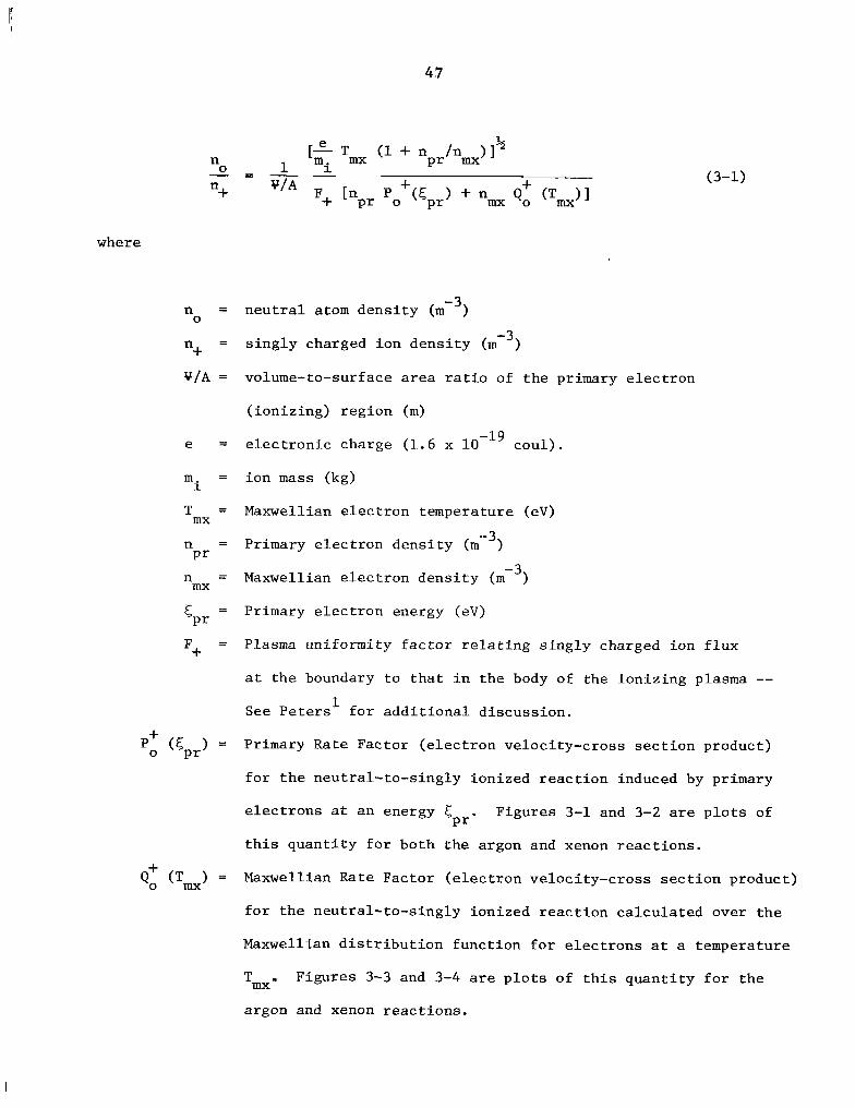
--
40
where
n = n e u t r a l atom d e n s i t y (m-3)0
-3 n4- = s i n g l y charged ion d e n s i t y (m )
V I A = volume-to-surface area r a t i o of t h e primary e l e c t r o n
( ion iz ing ) r eg ion (m)
e = e l e c t r o n i c charge (1 .6 x lo-'' coul) . mi = i on m a s s (kg)
T = Maxwellian e l e c t r o n temperature (eV)mx
n = Primary e l e c t r o n d e n s i t y (m -3 )P r
n = Maxwellian e l e c t r o n d e n s i t y (m-3 )mx
<Pr = Primary e l e c t r o n energy (eV)
F+ = Plasma uniformity f a c t o r r e l a t i n g s i n g l y charged ion f l u x
a t t h e boundary t o t h a t i n t h e body of t he i o n i z i n g p lasma
See Peters' f o r a d d i t i o n a l d i scuss ion .
P+ (5
P r ) = Primary R a t e Factor ( e l e c t r o n ve loc i ty -c ross s e c t i o n product)
0
f o r t h e neu t r a l - to - s ing ly ionized r e a c t i o n induced by primary
e l e c t r o n s a t a n energy 5P r - Figures 3-1 and 3-2 are p l o t s of
t h i s q u a n t i t y f o r both t h e argon and xenon r e a c t i o n s .
+Q (T ) = Maxwellian R a t e Fac to r ( e l e c t r o n ve loc i ty -c ross s e c t i o n product)o mx
f o r t h e neu t r a l - to - s ing ly ion ized r e a c t i o n c a l c u l a t e d over t h e
Maxwellian d i s t r i b u t i o n func t ion f o r e l e c t r o n s a t a temperature
Tmx F igures 3-3 and 3-4 are p l o t s of t h i s q u a n t i t y f o r t h e
argon and xenon r e a c t i o n s .

48
Fig. 3-1: Primary rate f ac to r P-i-for argon as a function of primary electron 0
energy.

49
x 10-14 201
II 1I
0 1 Q ) I I n E 151 iI+- I
1 no II 1
I
III
L
L 0 c I oi
I I I II
0 0 LL I Q)t I
1I
0 a I % L. 5iI
I .-E e' I
II
I II
1 20 40 50 70
Primary Electron Energy, cpr,e V
Fig. 3-2: Primary rate f a c t o r P+ f o r xenon as a func t ion of primary e l e c t r o n 0
energy.

0 5 IO 15 20 25 Maxwellion Electron Temperature, Tmx, e V
Fig. 3-3: Maxwellian rate factor Qu for argon as a function of 0
Maxwellian electron temperature.

52
20 25 Maxwellion Electron Temperature, T i R , eV
Fig . 3-4: Maxwellian rate f a c t o r Q' f o r xenon a s a func t ion of 0
Maxwellian e l e c t r o n temperature .
I
--
52
+ +Cross s e c t i o n s used t o c a l c u l a t e P
0 and Q
0 and o t h e r rate f a c t o r s
3used i n t h i s a n a l y s i s have been obtained from K i e f f e r and Dunn.
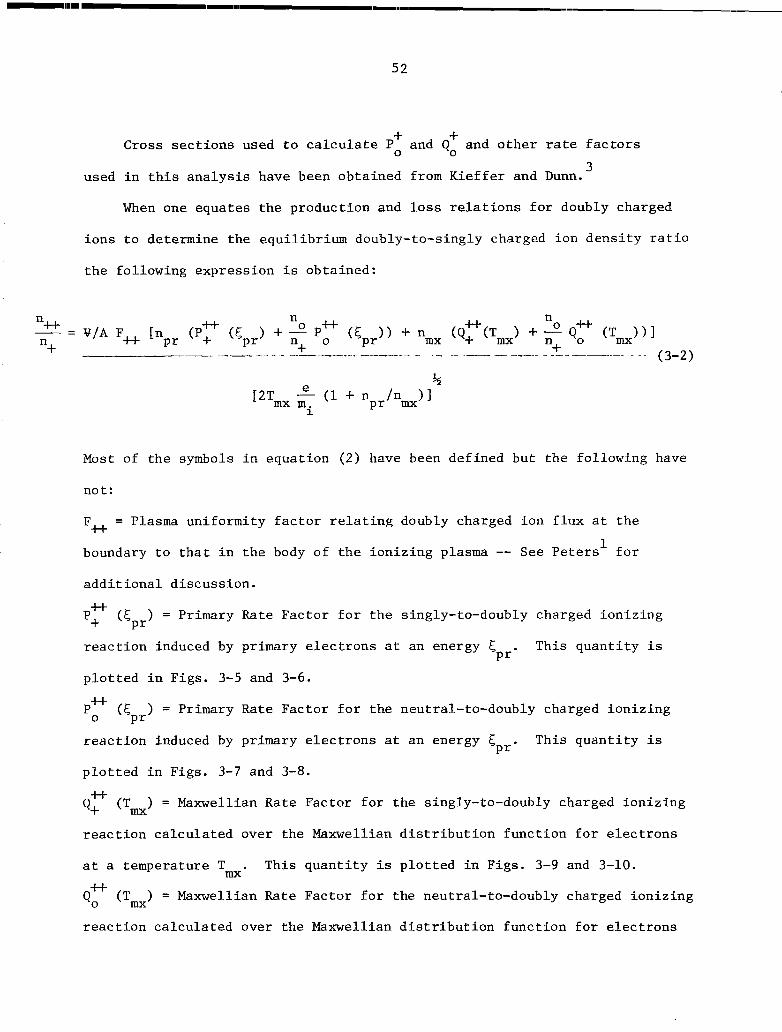
When one equates t h e product ion and l o s s r e l a t i o n s f o r doubly charged
i o n s t o determine t h e equ i l ib r ium doubly-to-singly charged ion d e n s i t y r a t i o
t h e fol lowing expression i s obtained:
+ -e (1+ n
P r /n&l[2Tmx mi
Most of t h e symbols i n equat ion ( 2 ) have been def ined but t h e fol lowing have
not:
F* = Plasma uniformity f a c t o r r e l a t i n g doubly charged ion f l u x a t t h e
boundary t o t h a t i n t h e body of t h e i o n i z i n g plasma See Peters' f o r
a d d i t i o n a l d i scuss ion .
P+ U
([ P r
) = Primary Rate Fac to r f o r t h e singly-to-doubly charged i o n i z i n g
r e a c t i o n induced by primary e l e c t r o n s a t an energy 5P r '
This q u a n t i t y i s
p l o t t e d i n Figs . 3-5 and 3-6 .
Pu (5P r
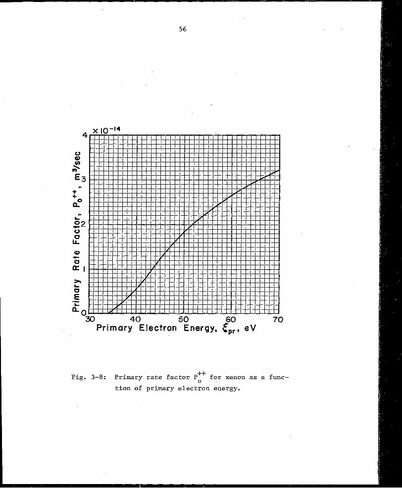
) = Primary R a t e Factor f o r t h e neutral-to-doubly charged i o n i z i n g
r e a c t i o n induced by primary e l e c t r o n s a t an energy 5P r *
This q u a n t i t y i s
p l o t t e d i n Figs. 3-7 and 3-8.
Q+ U (Tmx) = Maxwellian R a t e Factor f o r t h e singly-to-doubly charged i o n i z i n g
r e a c t i o n c a l c u l a t e d over t h e Maxwellian d i s t r i b u t i o n f u n c t i o n f o r e l e c t r o n s
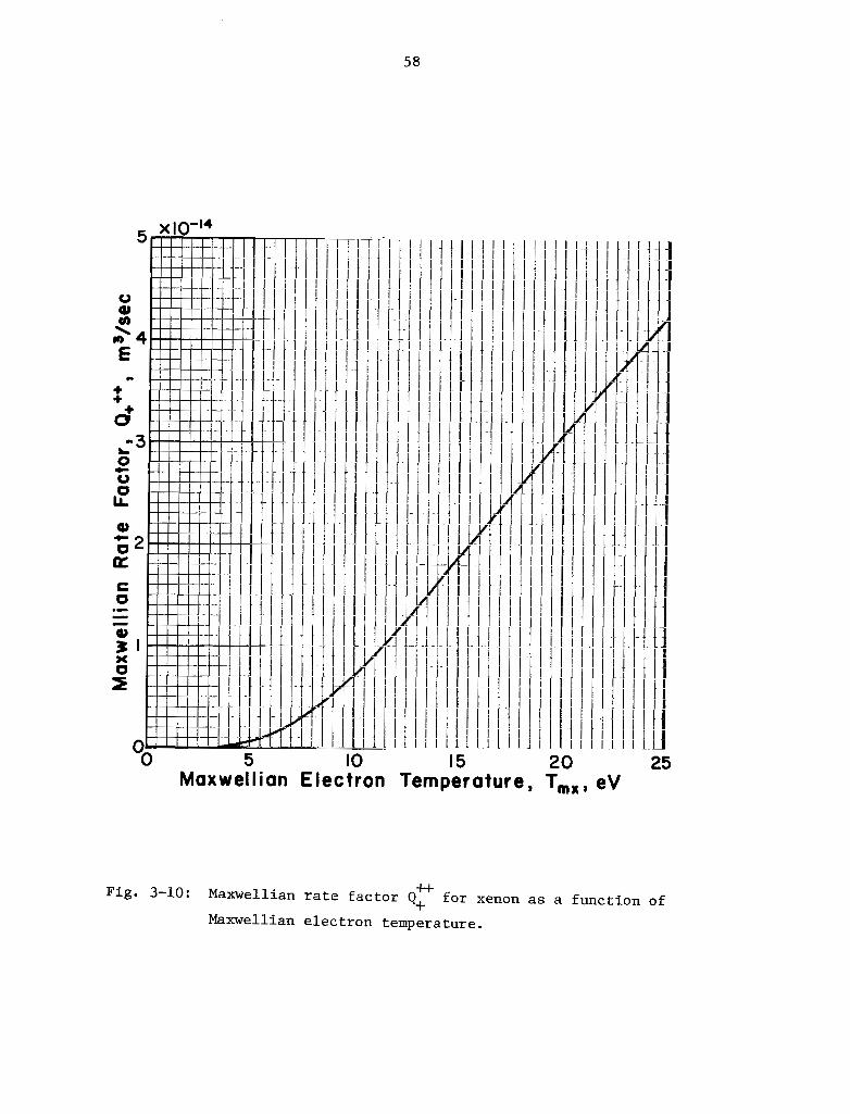
a t a temperature T . This q u a n t i t y i s p l o t t e d i n Figs . 3-9 and 3-10. m x ii-
Qo (Tmx) = Maxwellian Rate Fac to r f o r t h e neutral-to-doubly charged i o n i z i n g
r e a c t i o n c a l c u l a t e d over t he Maxwellian d i s t r i b u t i o n f u n c t i o n f o r e l e c t r o n s
0

53
XIO-14
5
0 Q)
n � 4
+ .. 2 .. L 0+ 3 0 0 LL
4) t 0
a 2 )5L
.-E L e
I
L5; -I
30 40 50 Primary Electron Energy, Epr, eV
Fig. 3-5: Primary rate f a c t o r P*+ f o r argon a s a func t ion of p r i
mary e l e c t r o n energy.

.I I. ..... ._ __ __.....
51i
0 0)e n E
L+++ In
L
L 0 c 0 0 lL
Q) c 0 a )rL 0
.-E e"
20 30 40 50 60 70 Primary Electron Energy, Cpr, eV
Fig. 3-6: Primary rate f a c t o r Pu+ f o r xenon as a func t ion of
primary e l e c t r o n energy.

55
0.8I X I (
I
+i eo I
I
II
I L
5 1 "0 0.41 0
1L L IIa3 c I 0 I
z? 0.2,
II I
Io ! -
40 50 70 Primary Electron Energy&, e V
Fig. 3-7: Primary rate f a c t o r P* f o r argon as 0
a func t ion of primary e l e c t r o n energy.
fn-14
40 50 60 70 Primary Electron Ewes
Fig. 3-8: Primary rate factor P* for xenon as a func0
t i o n of primary e lec t ron energy.

57
2
0 5 15 20 25 Maxwellion Electron Temperature, Tmx, eV
F i g . 3-9: Maxwellian rate factor Q*+ for argon as a function of
Maxwellian electron temperature.
58
T 1 1 I I 1
I 1iI I 1I !
I I 1I I 1I I 1
I 1I 1
I 1I 1 1
I LI I. I
I 1I I 1 1
1 1I 1 1I I I
I t1 1I I1 1I !1 1I 1f I
I
II 1 -
III
1
II
#I I
I 1 1II
I II 1I 1I' I I
L 1- I I I 1
1 1z I 11 I I
I 1II I 1
I I f c 1 1
iI i
U IO 15 20 MaxwelIian Electron Temperature, Tmx,eV
Fig. 3-10: Maxwellian rate factor Q+I- for xenon as a function of+ Maxwellian electron temperature.
25
59
a t a temperature T . This q u a n t i t y i s p l o t t e d i n Figs . 3-11 and 3-12. mx
The d a t a used t o c o n s t r u c t Figs . 1-12 are a l s o presented i n Table 3-1.
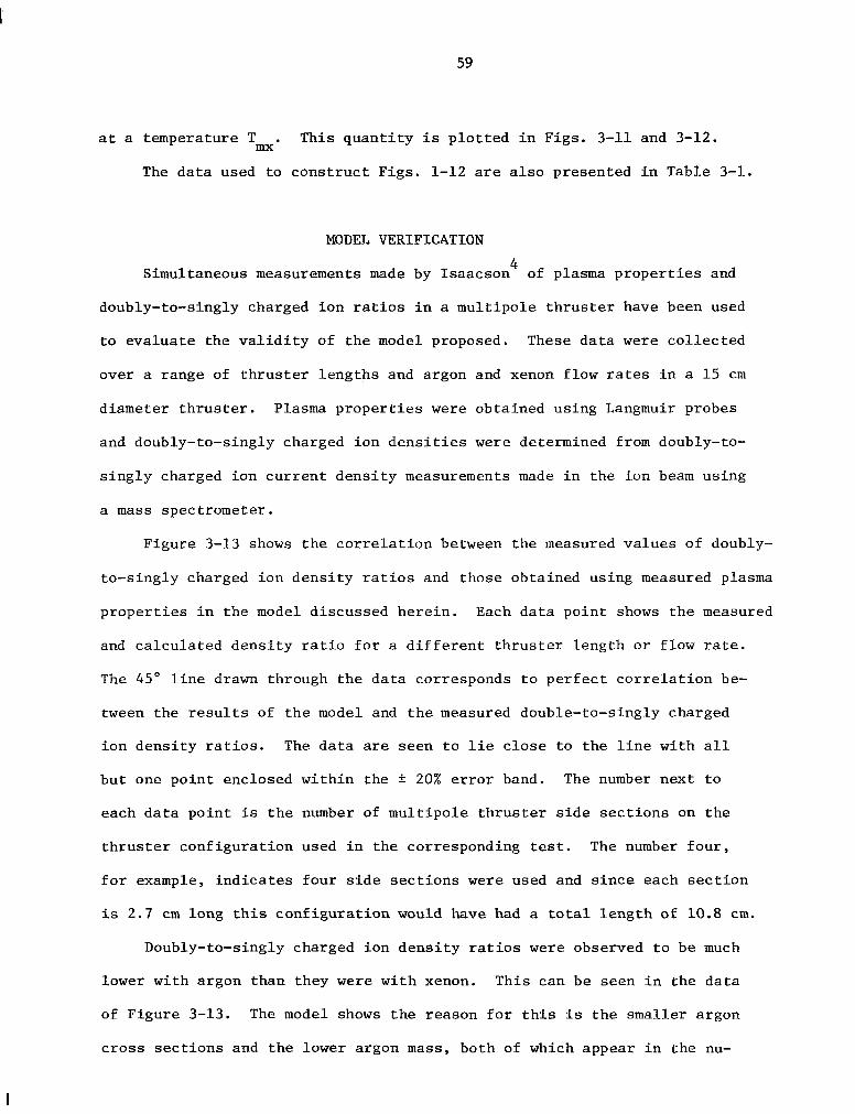
MODEL VERIFICATION
4Simultaneous measurements made by Isaacson of plasma p r o p e r t i e s and
doubly-to-singly charged i o n r a t i o s i n a mul t ipo le t h r u s t e r have been used
t o e v a l u a t e the v a l i d i t y of t h e model proposed. These d a t a w e r e c o l l e c t e d
over a range of t h r u s t e r l e n g t h s and argon and xenon flow rates i n a 15 cm
diameter t h r u s t e r . Plasma p r o p e r t i e s w e r e obtained using Langmuir probes
and doubly-to-singly charged i o n d e n s i t i e s w e r e determined from doubly-to
s i n g l y charged ion c u r r e n t d e n s i t y measurements made i n t h e ion beam using
a m a s s spectrometer .
F igu re 3-13 shows t h e c o r r e l a t i o n between t h e measured v a l u e s of doubly
to-s ingly charged i o n d e n s i t y r a t i o s and those obtained using measured p lasma
p r o p e r t i e s i n t h e model discussed h e r e i n . Each d a t a p o i n t shows t h e measured
and c a l c u l a t e d d e n s i t y r a t i o f o r a d i f f e r e n t t h r u s t e r l e n g t h o r flow rate .
The 45" l i n e drawn through t h e d a t a corresponds t o p e r f e c t c o r r e l a t i o n be
tween the r e s u l t s of t h e model and t h e measured double-to-singly charged
ion d e n s i t y r a t i o s . The d a t a are seen t o l i e c l o s e t o t h e l i n e with a l l
b u t one p o i n t enclosed w i t h i n the i 20% e r r o r band. The number nex t t o
each d a t a p o i n t is t h e number of mul t ipo le t h r u s t e r s i d e s e c t i o n s on t h e
t h r u s t e r conf igu ra t ion used i n t h e corresponding tes t . The number f o u r ,
f o r example, i n d i c a t e s fou r s i d e s e c t i o n s w e r e used and s i n c e each s e c t i o n
is 2.7 c m long t h i s c o n f i g u r a t i o n would have had a t o t a l l e n g t h of 10.8 cm.
Doubly-to-singly charged i o n d e n s i t y r a t i o s w e r e observed t o be much
lower with argon than they w e r e w i t h xenon. Th i s can be seen i n t h e d a t a
of Figure 3-13. The model shows t h e reason f o r t h i s i s t h e smaller argon
c r o s s s e c t i o n s and t h e lower argon m a s s , both of which appear i n t h e nu
l

0.2 le1 :IAY If l l I I I I
0.2 I I I I I I I I I I I I I I I 1 I I I I
'0. I II III I I I
III I I I I I
0.I I 1 I I I I I I I I I I I I I I I I
0.0 I!I I I I I I I I I I I I I 1 I I I I
0 ! J 5 IO 15 20 25
Maxwellian Electron Temperature, Tmx, eV
Fig. 3-11: Maxwellian rate f a c t o r Q* f o r argon a s a func t ion of Max0
w e l l i a n e l e c t r o n temperature.

I .o, XIO-14
0 10 15 Maxwellian Electron Temperature, Tmx,eV
Fig. 3-12: Maxwellian rate factor Q* for xenon as a function of Max0
wellian electron temperatures.

Table 3-1 - Rate Fac tors
ARGON
Temp
( e n
3 0.019 10-l~ 0.0001
4 0.086 0.002 --5 0.22 0.008 0.002 10-l~
6 0.41 0.004 x 0.025 0.17 -7 0.66 0.012 0.053 0.39
8 0.95 0.029 0.097 0.60 0.245 x 9 1.26 0.057 0.15 0.77 1.04
-1 0 1.58 0.099 0.23 0.89 1.90
12 2.25 0.23 0.40 0.99 0.05 2.76
15 3.24 0.55 0.73 1.06 0.17 3.55
18 4.15 0.99 1.10 1.15 0.44 4.89
21 4.98 1.52 1.49 1.26 0.75 5.94
24 5.72 2.10 1.88 1.32 1.07 6.73
27 6.38 2.71 2.25 1.35 1.32 7.33
30 6.98 3.33 2.61 1.33 1.45 7.83
3 0.009 x - 0.002 10-l~ - - -4 0.032 0.0003 x 0.014 - - -5 0.071 0.0018 0.051 .13 10-l~ - -6 0.12 0.0063 0.12 .63 - -7 0.18 0.016 0.23 1.00 - 0.071 x
8 0.24 0.032 0.37 1 . 2 9 0.25 -9 0.31 0.055 0.53 1.51 0.065 10-l~ 0.42
10 0.37 0.085 0.73 1.64 0.50 0.57 12 0.50 0.166 1.16 1 . 7 4 1.27 0.69
15 0.67 0.327 1.89 1.79 1.86 0.80 18 0.82 0.517 2.63 1.82 2.64 0.97 21 0.95 0.721 3.35 1.97 3.20 1.09 24 1.06 0.925 4.02 2.10 3.63 1.18
27 1.16 1.13 4.65 2.18 3.99 1.24 30 1.25 1.32 5.22 2.19 4.36 1.29
Energy
(ev)
5
10
15
20
25
30
35
40
45
50
60
70
ao 90
100
XENON
5
10
15
20
25
30
35
40
45
50
60
70
ao 90
100

6 3
o Xenon A Argon
1 .I_V _. 1 1 I J
(2)Measured (%)
Fig. 3-13: Double-to-single ion density ratio. Correlation
between theory and experiment.
6&
merator of equa t ion (3-2).
Considerat ion of t h e relative magnitude of each of t h e terms of Equa
t i o n (2) shows t h e relative c o n t r i b u t i o n of each of t h e p rocesses and
i o n i z i n g s p e c i e s considered i n t h e a n a l y s i s . Such an examination r e v e a l s
t h a t doubly charged i o n s are produced by bo th primary and Maxwellian
e l e c t r o n s i n s i g n i f i c a n t numbers f o r both argon and xenon. Likewise
doubly charged i o n s are produced by both one (neutral-to-doubly ion ized )
and two s t e p (neu t r a l - to - s ing ly ion ized followed by singly-to-doubly ion ized )
processes .
CONCLUSION
The model developed by Peters ' t o c a l c u l a t e t h e r a t i o of doubly-to
s i n g l y charged i o n s i n a mercury d i scha rge chamber can be app l i ed f o r s imi l a r
c a l c u l a t i o n s i n argon and xenon plasmas. Only n e u t r a l , s i n g l y ion ized and
doubly ionized ground s ta te atoms need be considered i n t h e a n a l y s i s .
Double-to-single i o n d e n s i t y r a t i o s c l a c u l a t e d from average p lasma p r o p e r t i e s
i n t h e d i scha rge chamber can be expected t o ag ree wi th measured va lues t o
w i t h i n k 20%.

I
65
I V - PROPELLANT ISOLATOR
by Raymond S. Robinson
Supplying a p r o p e l l a n t t o a t h r u s t e r u s u a l l y r e q u i r e s
electrical i s o l a t i o n between t h e d i scha rge chamber and t h e source of
t h e p r o p e l l a n t , which is u s u a l l y a t ground ( s p a c e c r a f t ) p o t e n t i a l . The
arrangement of t h r u s t e r and i s o l a t o r used i n t h i s i n v e s t i g a t i o n i s shown
i n Fig. 4-1. S t a i n l e s s steel tubing wi th an i n s i d e diameter of 1.6 mm
w a s used between t h e gas supply and t h e i s o l a t o r , and between t h e i s o l a t o r
and t h e t h r u s t e r . About 8 c m of tubing w e r e used between t h e i s o l a t o r
and a manifold, from which fou r tubes went t o t h e t h r u s t e r (only two
shown i n Fig. 4-1). The s h o r t e s t of t h e s e fou r tubes w a s about 15 cm,
so t h a t t h e minimum tube l e n g t h from t h e i s o l a t o r t o t h e t h r u s t e r w a s
about 23 cm. There w a s an a d d i t i o n a l several cen t ime te r s of p a t h l e n g t h
i n t h e p r o p e l l a n t d i s t r i b u t o r w i t h i n t h e t h r u s t e r .
The i s o l a t o r c o n f i g u r a t i o n s t e s t e d are shown i n Fig. 4-2. Aluminum
oxide tub ing wi th an i n s i d e diameter of 3 . 2 ntm w a s used f o r all t h e i s o l a t o r
bodies. Configurat ion I w a s a simple tube wi th an i n s u l a t i n g l e n g t h of
7.7 cm. For c o n f i g u r a t i o n 11, t h e i n s u l a t i n g l e n g t h w a s i nc reased t o 18.4 cm.
The c o n f i g u r a t i o n I1 i s o l a t o r body w a s used i n c o n f i g u r a t i o n 111, b u t two
de-ionizing pads o f f i n e steel wool w e r e a l s o used. These pads w e r e about
0.5 c m long and l o c a t e d so t h a t t h e tube w a s d iv ided i n t o t h r e e equal
segments. The p r o p e l l a n t w a s argon.
The test r e s u l t s are shown i n Fig. 4-3 f o r an o p e r a t i n g t h r u s t e r .
Breakdowns w e r e observed as c u r r e n t su rges o f several hundred mil l iamperes i n t h e
beam power supply, t o g e t h e r w i th b r i g h t b l u e o r pink glows through t h e i s o l a t o r
w a l l s . Configurat ions I and I1 w e r e s i n g l e segment i s o l a t o r s , so t h e
breakdown p o t e n t i a l d i f f e r e n c e shown w a s f o r t h e e n t i r e i s o l a t o r . Flows
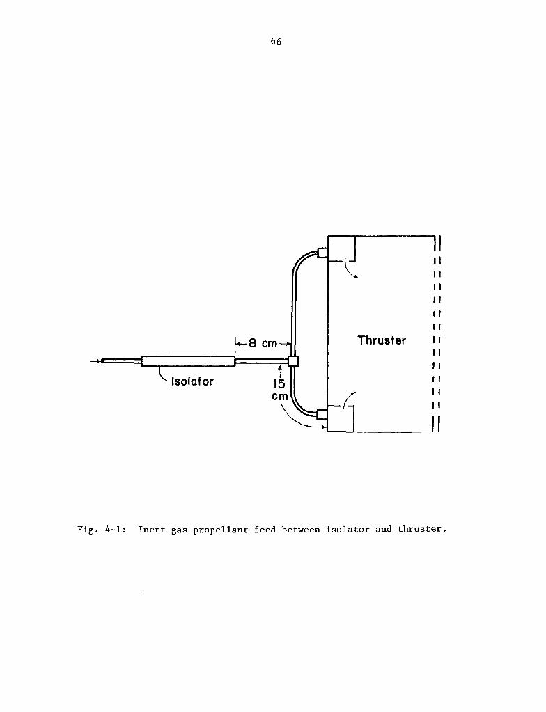
66
-I1'I I' I I I l It I f
I I
Thruster I I I I
I I I I
I t I I
Fig . 4-1: I n e r t gas p r o p e l l a n t feed between i s o l a t o r and t h r u s t e r .

. 1 c s 1
1- 7.7 cm -4
(01 Configuration I
I
. .. 1 1 - t II'18.4 cm-T
(b) Configuration II
(c) Configuration m
Fig. 4-2: Isolator configurations tested.
C

68
600r T ->
-400 I
- 8m -200
-
0 ~ - 1 ___ I I 4
Fig . 4 - 3 : Breakdown v o l t a g e s p e r i s o l a t o r segment, wi th t h r u s t e r
opera t ing .

69
ranged from 630 t o 1000 mfi-equivalent f o r conf igu ra t ion I and from
600 t o 1200 mA-equivalent f o r conf igu ra t ion 11. Note t h a t t h e r e w a s
no s i g n i f i c a n t d i f f e r e n c e i n breakdown v o l t a g e f o r more than a f a c t o r
of two i n c r e a s e i n l eng th . For c o n f i g u r a t i o n 111, t h e v o l t a g e p e r seg
ment w a s assumed t o be one-third of t h e t o t a l vo l t age . This assumption
gave a breakdown v o l t a g e per segment of about two-thirds of t h e v a l u e s
found f o r conf igu ra t ions I and 11. This d i f f e r e n c e i n d i c a t e s t h a t t h e
v o l t a g e d i v i s i o n between segments might b e less even than assumed. The
flows ranged from about 90 t o 1000 mA-equivalent f o r conf igu ra t ion 111.
Severa l hours of ope ra t ion were observed a t 1000 V ( 3 3 3 V p e r segment)
w i th no breakdowns a t 600 mA-equivalent, o r more. This absence of
breakdown i s i n d i c a t e d i n Fig. 4-3 by t h e absence of an upper e r r o r b a r
f o r t h a t conf igu ra t ion .
Observations w e r e a l s o made wi th s i m i l a r p r o p e l l a n t f lows, bu t no
t h r u s t e r d i scha rge . The breakdown p o t e n t i a l d i f f e r e n c e s under t h e s e
cond i t ions w e r e s e v e r a l t i m e s a s h igh as those shown i n Fig. 4-3. From
v i s u a l obse rva t ions of t h e breakdowns, t h e r e w a s no doubt t h a t t h e break
downs w e r e occu r r ing i n s i d e of t h e i s o l a t o r both wi th and without d i s
charge. Apparently, then, some charged p a r t i c l e s w e r e a b l e t o t r a v e r s e
t h e s t a i n l e s s steel tube between t h e t h r u s t e r and t h e i s o l a t o r . Th i s
t r a v e r s a l is impressive inasmuch as t h e tubing w a s curved and had a
t o t a l length-to-diameter r a t i o g r e a t e r than 140: l . Because charged
p a r t i c l e s could reach t h e i s o l a t o r from t h e t h r u s t e r , an a d d i t i o n a l s t e e l
wool pad between t h e i s o l a t o r and t h e t h r u s t e r would be expected t o improve
t h e i s o l a t o r performance.
I

70
V - CONCLUDING-REMARKS
A s mentioned i n t h e I n t r o d u c t i o n , t h e advances i n discharge-chamber
technology obtained under t h i s Grant have been included i n a n earlier pub
l i c a t i o n .
Hollow cathode d a t a w e r e obtained f o r a wide range of o p e r a t i n g condi
t i o n s . No l i f e t i m e tests were conducted, b u t some n e u t r a l i z e r test cond i t ions
gave plasma coupl ing v o l t a g e s a t o r below t h e s p u t t e r i n g th re sho ld . Such
cond i t ions should permit long o p e r a t i n g l i f e t i m e s .
A l l experimental obse rva t ions of hollow cathodes w e r e c o n s i s t e n t w i th
a s i n g l e comprehensive theory of ope ra t ion . That theory assumes a combination
of thermionic and high f i e l d emission a t l o c a l i z e d a r e a s w i t h i n t h e o r i f i c e .
This emission is assumed t o e x i s t a t a l l cond i t ions normally of i n t e r e s t i n
electric propuls ion and supplements t h e emission from t h e i n s e r t . The
emission from l o c a l i z e d h o t s p o t s i s supported by scanning e l e c t r o n micro
scope (SEM) photographs, which i n d i c a t e l o c a l i z e d melt ing has occurred at.
t h e tungsten t i p nea r t h e o r i f i c e . I n t h i s t heo ry , t h e d i f f e r e n c e between
spo t and plume modes is a f u n c t i o n p r i m a r i l y of t h e n e u t r a l d e n s i t y a t t h e
e x i t of t h e o r i f i c e . I n t h e s p o t mode, a high n e u t r a l d e n s i t y c a r r i e s t h e
i o n s i n t o t h e plume reg ion , e f f e c t i v e l y n e u t r a l i z i n g t h e space charge of t h e
e l e c t r o n s . I n t h e plume mode, t h e low n e u t r a l d e n s i t y does no t c a r r y t h e i o n s
i n t h i s manner. I n s t e a d , t h e i o n s are generated w i t h i n t h e plume reg ion ,
g iv ing rise t o t h e usua l glow a s s o c i a t e d with t h i s mode. With i n e r t gases ,
though, t h e absence o r presence of t h i s glow w a s found t o b e a less d e f i n i t i v e
i n d i c a t o r of mode than wi th mercury.
Experimental hollow cathode performance wi th argon, krypton, and xenon
p r o p e l l a n t s w a s c o r r e l a t e d . Two o r i f i c e s i z e s w e r e used w i t h argon and

a range of flow rates w a s used w i t h each of t h e t h r e e p r o p e l l a n t s . The para
meters used i n t h i s performance c o r r e l a t i o n are c o n s i s t e n t w i th t h e theo ry
desc r ibed above. For example, t h e emission parameter used is p ropor t iona l t o
t h e square of t h e e lec t r ic f i e l d i n t h e o r i f i c e sheath. Also, t h e flow para
m e t e r t h a t i n d i c a t e s t h e t r a n s i t i o n between spo t and plume modes i s propor
t i o n a l t o t h e o r i f i c e diameter d iv ided by mean f r e e path. The degree of
c o r r e l a t i o n obtained w a s e x c e l l e n t , cons ide r ing t h e prel iminary n a t u r e of t h e
c o r r e l a t i o n s tudy.
The b a s i c theory f o r product ion of doubly ionized argon and xenon h a s
been completed. Experimental measurements of t h e doubly ionized f r a c t i o n
ag ree w i t h theory w i t h i n about 220 percen t f o r t h e conf igu ra t ions and o p e r a t i n g
cond i t ions t e s t e d . Both t h e n e u t r a l t o doubly ion ized and s i n g l y t o doubly
ionized p rocesses are important i n t h i s theory. This r e s u l t d i f f e r s from
t h a t of mercury p r o p e l l a n t , where t h e n e u t r a l t o doubly ionized process w a s less
important. Because both processes are important w i th argon and xenon, decreas
ing t h e d i scha rge d e n s i t y w i l l no t be as h e l p f u l as wi th mercury i n reducing
t h e f r a c t i o n of doubly ionized atoms.
For t h e i s o l a t o r segment l e n g t h s i n v e s t i g a t e d , t h e breakdown v o l t a g e pe r
segment ranged from 300 t o over 500 V. Mul t ip l e segment i s o l a t o r s should
permit any reasonable t o t a l i s o l a t i o n v o l t a g e f o r e lec t r ic propuls ion t o b e
s u s t a i n e d without breakdown. The d i f f e r e n c e between an ope ra t ing d i scha rge
chamber and no d i scha rge w a s a f a c t o r of several i n i s o l a t o r breakdown v o l t a g e ,
c l e a r l y i n d i c a t i n g t h a t some charged p a r t i c l e s can t r a v e r s e a feed tube w i t h
a length-to-diameter r a t i o of more than 140:l.

72
REFERENCES
SECTION I
1. Isaacson, G. C . , "Multipole G a s Thrus t e r Design," NASA Con,tractor-
Report CR-135101, June 1977.
SECTION I1
-i__---1. Kaufman, H. R . , " I n e r t Gas Thrus te rs , " NASA Cont rac tor Report CR-135100, J u l y 1976.
2. S t u a r t , R. V . , and Wehner, G. K . , "Sput ter ing Yie lds a t Very Low _-Bombarding Ion Energies ," J . Applied Physics , Vol. 33, pp. 2345-2352,
J u l y 1962.
3 . Askerov, Sh. G . , and Sena, L. A . , "Cathode Spu t t e r ing of Metals by Slow Mercury Ions," S o v i e t Phys ics - S o l i d S t a t e , Vol. 11, pp. 1288-1293, Dec. 1969.
4. Sovey, J. S . , " C h a r a c t e r i s t i c s of a 30-cm D i a m e t e r Argon Ion Source," AIAA Paper N o . 76-1017, Nov. 1976.
5. Isaacson, G. C . , "Thick Sheath Langmuir Probe Analysis ," Appendix B i n NASA Cont rac tor Report CR-134755, Dec. 1974.
6. Wilbur, P. J . , "15 c m Mercury Ion Thrus t e r Research - 1976," NASA Contrac tor Report CR-135116, Dec. 1976.
7. Kaufman, H . R . , " I n t e r a c t i o n of a S o l a r Array wi th a n Ion Thrus te r due t o t h e Charge-Echange Plasma," NASA Cont rac tor Report CR-135099, O c t . 1976.
8. Rawlin, V. K . , and Pawlik, E. V . , "Mercury Plasma-Bridge Neu t ra l i ze r , " AIAA Paper No. 67-670, Sep t . 1967.
9 . Csiky, G. A . , "Measurements of Some P r o p e r t i e s of a Discharge from a -~Cathode," NASA Tech. Note- -.. . TN D-4966, Feb. 1969. (A s h o r t e r v e r s i o n
i s g iven i n J. Spacecr. Rockets, V o l . 7, pp. 474-475, Apr. 1970.)
10. Wilbur, P. J . , Monthly Report on NASA Grant NGR-06-002-112, Aug. 5 , 1977.
11. Cobine, J . D . , Gaseous Condu-ctors, pp. 246-247, Dover P u b l i c a t i o n s , New York, 1958.
12. Wilbur, P. J . , "15 c m Mercury Ion Thrus t e r Research - 1975," NASA Contrac tor Report CR-134905, Dec. 1975.

73
13. Bessling, H., "Theorie de Hochtemperatur-Hohlkathode, ein Model1 fiir den Kathodmechanismus," Deutsche Luft - und Raumfahrt, Forschungsbericht DLR-FB 76-50, 1976.
14. Anderson, G. S., "Hg Adsorption Studies Using Atom Ejection Patterns," J. App. Physics, Vol. 36, pp. 1558-1561, May 1965.
15. Newsome, D. S., "Significant Structure Theory of Multilayer Physical Adsorption," J. Physical Chemistry, Vol. 78, pp. 2600-2604, 1974.
16. Rehn, L. A., "Argon Hollow Cathode," NASA Contractor Report CR-135102 (Appendix), Nov. 1976.
17. Snyder, A., and Banks, B. A., "Thrust Measurements of a Hollow-Cathode Discharge," NASA Tech. Note TN D-6705, Mar. 1972.
18. Kaufman, H. R., "Technology of Electron-Bombardment Ion Thrusters," in -Advances in Electroniss and-Ektron Physics, Vol. 36. (L. Marton, ed.), pp. 265--373,Academic Press, New York, 1974.
SECTION 111
1. Peters, R. R., "Double Ion Production in Mercury Thruster," NASA CR-135109, Apr. 1976.
2. Masek, T. D., "Plasma Properties and Performance of Mercury Ion Thrusters," AIM Paper No. 69-256, March 3-5, 1969.
3. Kieffer, L. J. , and G . H. Dunn, "Electron Impact Ionization Cross-section Data for Atoms, Atomic Ions, and Diatomic Molecules: I. Experimental Data," Rev. of Mod. Phys., Vol. 38, No. 1, pp. 1-35, Jan. 1966.
4 . Isaacson, G . , Private communication, Colorado State University, Feb. 1977.

DISTRIBUTION LIST
No. o f Copies
Nat iona l Aeronaut ics and Space A d m i n i s t r a t i o n Washington, D. C. 20546 A t t n : RPE/Mr. Wayne Hudson
Mr. Daniel H. Herman, Code SL
Nat iona l Aeronaut ics and Space A d m i n i s t r a t i o n Lewis Research Center 21000 Brookpark Road Cleveland, Ohio 44135 At tn : Research Support Procurement Sec t ion
M r . A l l e n Jones, MS 500-313 Technology U t i l i z a t i o n Off ice, MS 3-19 Report Cont ro l Off ice, MS 5-5 L i b r a r y , MS 60-3 N. T. Mus ia l , MS 600-113 Spacecraf t Technology D i v i s i o n , MS 501-8
M r . H. Douglass M r . R . F inke M r . D. Byers M r . B. Banks M r . S. Domitz M r . F. Terdan M r . W. Kerslake M r . Vincent K. Rawlin M r . F1. M i r t i c h
Physical Science D i v i s i o n , MS 301-1 M r . W. E . Moeckel
Nat iona l Aeronaut ics and Space A d m i n i s t r a t i o n Marshal l Space F l i g h t Center Huntsvi 11e , A1abama 35812 A t t n : M r . J e r r y P. Hethcoate
Research and Technology D i v i s i o n Wright-Patterson AFB, Ohio 45433 A t t n : (ADTN) L t . David A. Fromme
NASA S c i e n t i f i c and Technical I n f o r m a t i o n F a c i l i t y P. 0. Box 8757 Balt imore/Washington I n t e r n a t i o n a l A i r p o r t Bal t imore , Mary1and 21240
Case Western Reserve U n i v e r s i t y 10900 E u c l i d Avenue Cleveland, Ghio 44106 A t t n : D r . E l i Reshotko
Royal A i r c r a f t Establ ishment Space Department Farnborough, Hants, England Attn: D r . D. G. Fearn
1 1
1 1 1 1 1 1 1
20 1
1
1
1
40
1
1

United Kingdom Atomic Energy Authority C u l ham LaboratoryAbingdom, Berkshire, EnglandA t t n : Dr. P . J . Harbour
Dr. M . F . A . Harrison Dr. T. S. Green
National Aeronautics and Space Administration Goddard Space F l i g h t Center Greenbel t , Maryl and 20771 A t t n : Mr. W . I s l e y , Code 734
Mr. R. B a r t l e t t , Code 713 Mr. R . Ca l lens , Code 734
SAMSO Air Force Unit Post Off ice Los Angel es , Cal i fo rn ia 90045 A t t n : Capt. D . EganISYAX
Comsat Laboratories P. 0. Box 115 C1 arksburg , Maryl and 20734 A t t n : Mr. B. Free
Mr. 0. Revesz
Rocket Propulsion LaboratoryEdwards AFB, Ca l i forn ia 93523 A t t n : LKDA/Mr. Tom Waddell
DFVLR - I n s t i t u t fur P1 asmadynami k Technische Univers i ta t S t u t t g a r t7 Stuttgart-VaihingenA 1 lmandstr 124 West GermanyA t t n : Dr. G . Krulle
Mr. H . Bessling
Giessen Universi ty 1st I n s t i t u t e of PhysicsGiessen, West GermanyA t t n : Professor H. W . Loeb
J e t Propulsion Laboratory4800 Oak Grove Drive Pasadena, Cal i forn ia 91102 A t t n : Dr. Kenneth A t k i n s
Technical LibraryFr . Eugene Pawlik Mr. James Graf
Electro-Optical Systems, Inc. 300 North Halstead Pasadena, Cal i forn ia 91107 A t t n : Mr. R . Worlock
Mr. E . James Mr. W . Ramsey
1
1 1
2
1 1
1

TRW, Inc. TRW Systems One Space Park Redondo Beach, C a l i f o r n i a 90278 Attn: M r . M. Huberman
D r . J. M. S e l l e n D r . S. Za f ran
Na t iona l Aeronaut ics and Space A d m i n i s t r a t i o n Ames Research Center M o f f e t t F i e l d , C a l i f o r n i a 94035 A t t n : Technical L i b r a r y
Nat iona l Aeronaut ics and Space A d m i n i s t r a t i o n Langley Research Center Langley F i e l d S t a t i o n Hampton, V i r g i n i a 23365 A t t n : Technical L i b r a r y
Hughes Research Labora tor ies 3011 Mal ibu Canyon Road Mal ibu , Cal if o r n i a 90265 A t t n : D r . Jay Hymn
Mr. J. H. M o l i t o r D r . R . L. Poeschel M r . R . Vahrenkamp D r . John R. B e a t t i e
Un i ted States A i r Force O f f i c e o f S c i e n t i f i c Research Washington, D. C. 20025 A t t n : M r . M. Slawsky
Pr ince ton U n i v e r s i t y Pr ince ton , New Jersey 08540 A t t n : M r . W. F. Von Jaskowsky
Dean R . G. Jahn D r . K. E. C la rk
Communications Research Centre Ottawa , Ontar io , Canada A t t n : D r . W. F. Payne
J o i n t I n s t i t u t e f o r Labora tory As t rophys ics U n i v e r s i t y o f Colorado Boul der , Colorado 80302 Attn: D r . Gordon H. Dunn
Department o f Aeronaut ics and As t ronau t i cs Stanford U n i v e r s i t y Stanford , Cal if o r n i a 94305 A t t n : Pro fessor Howard S. S e i f e r t
1
1
1

Boeing Aerospace CompanyP. 0. Box 3999 S e a t t l e , Washington 98124 A t t n : Mr. Donald Grim
Intelcom Rad Tech 7650 Convoy Court P. 0. Box 80817 San Diego , Gal i fo rn i a 921 38 A t t n : Dr. David Vroom
Lockheed Missiles and Space CompanySunnyvale, Ca l i fo rn ia 94088 A t t n : Dr. William L . Owens
Propulsion Systems, Dept. 62-13
Fa i r ch i ld Republic CompanyFarmi ngdal e , New York 11735 A t t n : Dr. William Guman
COMSAT Corporation950 L'Enfant Plaza SW Washington, D . C . 20024 A t t n : Mr. Sidney 0. Metzger
El ec t ro t echn ica l LaboratoryTahashi Branch 5-4-1 Mukodai-Machi , Tanashi-Shi Tokyo, JapanA t t n : Dr. Katsuva Nakayama
Office of Ass i s t an t f o r Study SupportKirtland Air Force Base Albuquerque, New Mexico 87117 A t t n : Dr. Calvin W . Thomas OAS Ge
Dr. Berhart Eber OAS Ge
Bell Laboratories 600 Mountain Avenue Murray H i l l , New Je r sey 07974 A t t n : Dr. Edward G . Spencer
Dr. Paul H . Schmidt
Massachusetts I n s t i t u t e o f TechnologyLincoln LaboratoryP . 0. Box 73 Lexington, Massachusetts 02173 A t t n : Dr. H. I . Smith
Sandia Laboratories Mail Code 5742 Albuquerque, N.M. 87115 A t t n : Mr. Ralph R . Peters
1
1
1
1
1 1
1 1
Service du Confineme7t des Plasma Centre d'Etudes Nucleaires - F.A.R. B.P. 6 92260 Fontenay-aux-RosesFrance Attn: Dr. J. F. Bonal 1