Inelastic response of composite steel and concrete base ... · PDF fileInelastic response of...
14
Journal of Constructional Steel Research 63 (2007) 819–832 www.elsevier.com/locate/jcsr Inelastic response of composite steel and concrete base column connections L. Di Sarno a,* , M.R. Pecce a , G. Fabbrocino b a Department of Engineering, University of Sannio 82100, Benevento, Italy b Department S.A.V.A., University of Molise 86100, Campobasso, Italy Received 24 January 2006; accepted 8 August 2006 Abstract This paper assesses the experimental results of monotonic (pushover) tests carried out on partially encased composite steel–concrete columns connected to the foundation block through the traditional bolted steel end plate and an innovative socket type system. These tests show that the structural response of the traditional connection is significantly influenced by the behaviour of the anchorage bolts. The latter cause large fixed end rotations and possess limited energy dissipation. Conversely, innovative composite steel–concrete base column connections with socket systems exhibit adequate overstrength, inelastic deformations and energy absorption capacity. Furthermore, socket-type connections are characterized by spreading of inelasticity at the base of the composite columns without damage localization on concrete and interface components. It can thus be argued that the innovative connection type assessed in this study is a viable solution for applications in framed structures fulfilling capacity design requirements, e.g. structural systems in earthquake prone regions. c 2006 Elsevier Ltd. All rights reserved. Keywords: Composite columns; Partially encased columns; Base column joint; Socket-type connection; Overstrength; Ductility; Energy dissipation 1. Introduction Composite steel and concrete structural systems possess adequate seismic performance because of their stiffness, strength and ductility, and have been found to be cost- effective especially for multi-storey buildings under horizontal loads ([21,1,18] among many others). Composite systems for buildings often include steel moment resisting frames, consisting of steel beams (acting compositely with a metal deck reinforced slab or solid concrete slab through shear studs) and encased composite columns, or braced frame with steel–concrete composite columns [6]. Consequently, lateral drifts, both interstorey and roof drifts, under horizontal forces (wind and/or earthquakes) are lowered. Under severe earthquake loading concrete encasement cracks and reduces the flexural stiffness of composite beam–columns but the steel core acts as a back-up system in providing the shear strength and the ductility to prevent brittle failure. Partial encased beam–columns with local buckling inhibitors have been found * Corresponding address: Department of Engineering, University of Sannio, Piazza Roma, 21, Benevento, Italy. Tel.: +39 0824 305566; fax: +39 0824 325246. E-mail address: [email protected] (L. Di Sarno). very efficient to prevent local buckling and enhance the global stability of the frame, thus reducing sensitivity to P –Δ effects [12,11]. The assessment of structural response of composite steel and concrete columns is thus of paramount importance, especially in the earthquake design of framed systems ([13, 25], among many others). The inelastic response of composite columns is significantly affected by the beam–column, brace- to-beam, brace-to-column connections and column bases. A comprehensive review of the experimental tests carried out on steel–concrete composite beam–columns (both encased and concrete-filled) can be found, for instance, in [5,23]. It is noteworthy that, to date, analytical and experimental research focusing on the effects of the base connection layout on the performance of beam–columns, either partially or fully encased, is lacking [24]. Few results are available and were derived chiefly from the steel structures; their applicability within the capacity-design framework should be further investigated [17,19]. The composite action, may, however, affect the failure modes thus endangering the inelastic performance of the structural member (e.g. [7]). This paper analyzes the inelastic response of composite steel–concrete joints at column base. An innovative base column connection, employing a socket-type system, is discussed and its response is compared to that of a traditional 0143-974X/$ - see front matter c 2006 Elsevier Ltd. All rights reserved. doi:10.1016/j.jcsr.2006.08.007
Transcript of Inelastic response of composite steel and concrete base ... · PDF fileInelastic response of...

Journal of Constructional Steel Research 63 (2007) 819–832www.elsevier.com/locate/jcsr
Inelastic response of composite steel and concrete base column connections
L. Di Sarnoa,∗, M.R. Peccea, G. Fabbrocinob
a Department of Engineering, University of Sannio 82100, Benevento, Italyb Department S.A.V.A., University of Molise 86100, Campobasso, Italy
Received 24 January 2006; accepted 8 August 2006
Abstract
This paper assesses the experimental results of monotonic (pushover) tests carried out on partially encased composite steel–concrete columnsconnected to the foundation block through the traditional bolted steel end plate and an innovative socket type system. These tests show that thestructural response of the traditional connection is significantly influenced by the behaviour of the anchorage bolts. The latter cause large fixed endrotations and possess limited energy dissipation. Conversely, innovative composite steel–concrete base column connections with socket systemsexhibit adequate overstrength, inelastic deformations and energy absorption capacity. Furthermore, socket-type connections are characterized byspreading of inelasticity at the base of the composite columns without damage localization on concrete and interface components. It can thus beargued that the innovative connection type assessed in this study is a viable solution for applications in framed structures fulfilling capacity designrequirements, e.g. structural systems in earthquake prone regions.c© 2006 Elsevier Ltd. All rights reserved.
Keywords: Composite columns; Partially encased columns; Base column joint; Socket-type connection; Overstrength; Ductility; Energy dissipation
1. Introduction
Composite steel and concrete structural systems possessadequate seismic performance because of their stiffness,strength and ductility, and have been found to be cost-effective especially for multi-storey buildings under horizontalloads ([21,1,18] among many others). Composite systemsfor buildings often include steel moment resisting frames,consisting of steel beams (acting compositely with a metaldeck reinforced slab or solid concrete slab through shearstuds) and encased composite columns, or braced framewith steel–concrete composite columns [6]. Consequently,lateral drifts, both interstorey and roof drifts, under horizontalforces (wind and/or earthquakes) are lowered. Under severeearthquake loading concrete encasement cracks and reducesthe flexural stiffness of composite beam–columns but the steelcore acts as a back-up system in providing the shear strengthand the ductility to prevent brittle failure. Partial encasedbeam–columns with local buckling inhibitors have been found
∗ Corresponding address: Department of Engineering, University of Sannio,Piazza Roma, 21, Benevento, Italy. Tel.: +39 0824 305566; fax: +39 0824325246.
E-mail address: [email protected] (L. Di Sarno).
0143-974X/$ - see front matter c© 2006 Elsevier Ltd. All rights reserved.doi:10.1016/j.jcsr.2006.08.007
very efficient to prevent local buckling and enhance the globalstability of the frame, thus reducing sensitivity to P–∆ effects[12,11]. The assessment of structural response of compositesteel and concrete columns is thus of paramount importance,especially in the earthquake design of framed systems ([13,25], among many others). The inelastic response of compositecolumns is significantly affected by the beam–column, brace-to-beam, brace-to-column connections and column bases. Acomprehensive review of the experimental tests carried outon steel–concrete composite beam–columns (both encasedand concrete-filled) can be found, for instance, in [5,23].It is noteworthy that, to date, analytical and experimentalresearch focusing on the effects of the base connectionlayout on the performance of beam–columns, either partiallyor fully encased, is lacking [24]. Few results are availableand were derived chiefly from the steel structures; theirapplicability within the capacity-design framework shouldbe further investigated [17,19]. The composite action, may,however, affect the failure modes thus endangering the inelasticperformance of the structural member (e.g. [7]).
This paper analyzes the inelastic response of compositesteel–concrete joints at column base. An innovative basecolumn connection, employing a socket-type system, isdiscussed and its response is compared to that of a traditional

820 L. Di Sarno et al. / Journal of Constructional Steel Research 63 (2007) 819–832
steel base plate connection. The latter was designed incompliance with the rules utilized for the composite frametested at JRC Ispra laboratory [3,14]. Several tests under eithermonotonic or cyclic lateral loads and different levels of axialloads were performed. This work focuses on the responseof composite columns under monotonic regime, i.e. pushovertests. The results of the experiments carried out on specimenswith welded base steel plate (traditional) and socket-type jointsare discussed. It is found that for the traditional connections,concentrations of inelastic demand occur in the anchoragebolts and relies chiefly on bond type mechanisms. This typeof structural response is assessed with a simplified fibre-based numerical model. The latter allows the evaluation of thedifferent contributions of the lateral deformation at the top ofthe column specimens. Such model points out the large inelasticdemand imposed on the anchorage bolts of the steel endplate in traditional base column connections. Conversely, thesocket-type system, derived from precast reinforced concretestructures, leads to large energy dissipation. Plastic hinges format column base and the strength capacity is not lowered even atlarge lateral drifts (greater than 5%–6%). As a consequence,socket-type foundations may be reliably utilized for steeland composite steel–concrete framed structures, especially inregions with moderate-to-high seismicity, to achieve adequateseismic structural performance.
2. Experimental program and test set-up
Several research programmes were recently launched inEurope, the US and Japan to investigate the inelastic responseof bare steel and composite steel and concrete compositestructures and/or their subassemblages, both for new andexisting buildings (e.g. [22,7], among others). In Italy, a numberof experimental programmes were funded through nationaland European grants to provide technical support for theimplementation and improvement of seismic provisions andguidelines (e.g. [4,20,11]). These test programmes includedthe assessment of the seismic response of composite slabs,beam–columns and connections, either beam-to-column orbase columns. In particular, the authors of the present workinvestigated the inelastic static and dynamic (seismic) responseof base column connections. In so doing, a number of partialencased column specimens, with different base joints, weretested in the laboratory of the Department of StructuralAnalysis & Design (DAPS, University of Naples, Italy).The sample specimens included monotonic and cyclic tests;different levels of axial loads were considered during thetests to simulate the seismic load combinations implementedin European standards [11] for composite building structures.These axial loads were computed with regard to the exterior andinterior composite steel–concrete columns frame tested at JRCIspra laboratory [3,14], as shown in Fig. 1. In addition, pull-out tests were carried out to define the force–slip relationshipsof the hooked anchorage bolts; the results of the pull-outtests were utilized to investigate the deformation capacity ofthe base column traditional joint. In this work the results ofthe monotonic (pushover) tests are discussed in details. The
experiments were carried out on two types of partially encasedcomposite columns: HEB260 and HEB280 (see Fig. 1). Thetest specimens employed two layouts for the base columnjoints as per Fig. 2: traditional (bolted steel base plate) andinnovative (socket-type) joints. The former consist of taperedsteel plates welded onto base plates and anchored to thefoundation block through steel bolted bars (see also [14]). Thelatter is an alternative and innovative socket type joint in whichthe column is fixed to the foundation block utilizing a specialconcrete filler; such joint was developed and designed to benefitof composite action. Socket type connections are generallyutilized in precast reinforced concrete systems for residential,office and industrial framed structures.
The first set of specimens (traditional base columnconnections) correspond to the columns and base jointsdesigned in compliance with the guidelines of Europeanstandards [9–11] and used for the full-scale composite frametested in ISPRA [3]; the layout of the latter is pictoriallydisplayed in Fig. 1. The socket-type foundation was designedin compliance with Eurocode 2 [8] using strut-and-ties designapproach.
In the experimental tests, the lateral loads were appliedat two different locations along the height of the column,namely at 1.6 m (traditional joint) and 1.7 m (socket type)above the foundation block to account for the different locationof the restraint. Traditional base plates are generally placedat floor level, conversely socket type solution enables to usepavings that cover the foundation block. The horizontal load T ,simulating the earthquake loading, was applied by means of a500 kN-hydraulic jack; the test was under displacement control.As a consequence, the maximum flexural moments M , locatedat the base connection, was increased until failure occurred. Thedisplacement controlled loading regime allowed the softeningbranch of the response (capacity) curve to be investigated. Theconnection of the jack to the column is ensured by two steelplates 30 mm thick bolted on two opposite faces of the column.The reaction wall for the horizontal load is a stiff taperedcantilever bolted to a steel system; its layout is shown in Fig. 3along with the test set-up. The cantilever system is connected tothe laboratory floor slab (strong floor) by means of large steelrebars crossing the slab and the steel elements. These rebars areloaded in tension to prestress the connection. The vertical loadN is applied by two hydraulic jacks connected with two barsat the hinges placed at the foundation level. The axial load Nacts along the column centroid axis. The reaction system forN consists of a steel plate located under the foundation blockand connected to the hinges. This layout ensures that the loadremains along the member axis during the column deformation.The transversal beam, at the column top, is connected to thejack by means of large stiffeners. An adequate lateral restraintalong four prestressing bars at the corners were used to preventslip and rocking of the foundation block and to guarantee thetransfer of the shear forces to the strong floor level.
The investigation of the interface behaviour between anchor-age bolts and concrete block was carried out by means of pull-out tests; the set-up employed to perform the tests is provided

L. Di Sarno et al. / Journal of Constructional Steel Research 63 (2007) 819–832 821
Fig. 1. Geometry of the full-scale composite frame tested at Ispra.
in Fig. 4. It consists of a rigid steel frame, designed to preventthe onset of local buckling. The jack is bolted at the horizon-tal beam of the frame and the anchoring device is gripped witha tension bar. The anchoring devices were instrumented with atransducer and strain gauges. It is instructive to note that the useof strain gauges may, however, modify the mechanism associ-ated to bond and influence significantly the results due to localstresses acting on the device.
3. Test specimens
The experimental programme carried out at the laboratoryof DAPS, in Naples, focused on two sample partially encasedcomposite steel and concrete columns: HEB260 and HEB280(see also Fig. 1). The sample specimens tested were cantileversystems summarised as below (Table 1): partially encasedcolumns with a steel HEB 260 member and traditional

822 L. Di Sarno et al. / Journal of Constructional Steel Research 63 (2007) 819–832
Fig. 2. Layout of the sample base column connection: traditional (left) and socket-type (right).
Table 1Sample column specimens
Specimen Axial load (kN) Loading type Connection
HEB260 330 Monotonic TraditionalHEB260 170 Monotonic TraditionalHEB260 330 Monotonic SocketHEB280 520 Monotonic Socket
connection to foundation (stiffening plates and anchoringdevices) and innovative socket-type system; HEB280 withsocket-type foundation. The specimens were instrumented ina refined fashion to characterize reliably the concentration ofinelastic demand at the base column. Fig. 5 provides a close-upview of the displacement transducers (LVDTs) located at thebase of the partially encased columns with either traditional orinnovative joints.
The values of axial load N used in the tests were equal to170 kN, 330 kN and 520 kN. The latter values correspond tothe axial loads of the design load combinations of the full-scale composite framed building tested in the ELSA laboratoryof JRC in Ispra [3]. The grade of the structural steel of thespecimens was S235; the reinforcing bars grade was B450-C and the concrete was class C25/30. Actual values of themechanical properties of steel and concrete were estimatedfrom tensile (for steel) and compression (for concrete) tests.The values computed for the column members are summarizedin Table 2. The width-to-thickness ratios of the sample columns(b/t f = 20.8 for HEB260 and b/t f = 21.5 for HEB280)fulfil the limit (b/t f = 44) given in European standards [10]to prevent local buckling in partially-encased I-sections madeof steel grade S253. Further details on the results of such testscan be found in [3]. The values of material overstrength ( fu/ fy)
relative to the element flange are on average higher than those inthe webs. This result is in agreement with similar experimentaldata for steel members produced in Europe (e.g. [2]).
The details of the foundation system are shown in Fig. 2. Thedesign of such foundation block was based on the ultimate limitstate corresponding to the stress values and distribution at thecolumn failure. The layout of the composite column specimenemploying HEB 260 steel section and traditional base joint isprovided in Fig. 6, while the specimen HEB260 with sockettype connection is provided in Fig. 7. The thicknesses of the
Table 2Mechanical properties of the sample columns
Property HEB260 HEB280Web Flange Web Flange
fy (MPa) 406 341 341 300fu (MPa) 480 449 450 430fu/ fy 1.18 1.32 1.32 1.43εu (%) 31.8 35.7 34.5 37.1
base of the socket is equal to 300 mm, while the walls of thesocket are 250 mm thick. The total height of the foundationis 1050 mm. The values of the internal actions, i.e. axial loadNSd, j , flexural moment MSd, j and shear VSd, j used for thedesign are NSd, j = 308 kN, MSd, j = 906 kN m and VSd, j =
444 kN. These values were derived from the ultimate flexuralcapacity of the HEB 280; the evaluation of the resistance wasbased on conservative assumptions. In fact, for the above cross-section, the ultimate bending moment is MRd,col = 755 kN m;note that the design value MSd, j accounts for the overstrength( fu/ fy = 1.20) at the base column connection.
For each foundation block, two anchoring devices wereembedded in addition to the ones used for the base column jointdetails (Fig. 8). These embedded elements were instrumentedwith transducers and were utilized for pull-out tests. Thus,force–slip relationships were estimated for each anchoragebolts; these relationships were then utilized to compute themoment–curvature relationship of the base column section,as discussed in Section 5. The results of the experimentaltests carried out on composite columns employing innovative(socket-type) are discussed below.
4. Test results
The test results of the partially encased composite columnswere computed in terms of both local (moment–curvatureM– χ and moment–rotation M–θ ) and global (lateral load–topdisplacement, F–∆) response parameters. The capacity curvesof the specimens HEB260 with axial load N = 330 kN, bothtraditional and innovative base connections, are provided inFig. 9. Such curves are expressed in terms of lateral force(F)-drift (d/H), where H is the distance of the centrelineof the hydraulic jack from the foundation and d the total

L. Di Sarno et al. / Journal of Constructional Steel Research 63 (2007) 819–832 823
Fig. 3. Layout of the test set-up (top) and reaction wall (bottom).
horizontal displacement at the jack height. It is observed thatthe traditional connection layout exhibits higher lateral strength(600 kN m vs. 510 kN m) due to the steel stiffeners usedat the base of the column and to overstrength for seismicdesign. Conversely, the ultimate deformation capacity of thesocket type connection is about 75% higher than the counterparttraditional (about 0.05 rad vs. 0.09 rad); in both cases thethreshold value of 35 m rad given by Eurocode 8 [11] is
exceeded. The latter limit value is more stringent than the 3%drift, which is assumed as the onset of the ultimate limit state insteel and composite frames in the US practice [16]. Furthermorethe failure mode of the specimen with steel end plate is relatedto anchorage bolt fracture (Fig. 10), while in the case of thesocket type a very ductile mechanism is observed (Fig. 11).At serviceability, the stiffness of the traditional connectionis slightly higher than that of the socket connection. It can

824 L. Di Sarno et al. / Journal of Constructional Steel Research 63 (2007) 819–832
Fig. 4. Set-up of pull-out tests: layout (left) and actual system (right).
Fig. 5. Close-up view of the electrical displacement transducers (LVDTs): traditional (left) and innovative (right) joint.
thus be argued that the experimental tests carried out bothon traditional bolted steel end plate and innovative socket-type connections demonstrate that the former experience brittlefailure modes. Rupture of anchorage bolts as per Fig. 10 was
observed for traditional connections. The composite partiallyencased columns with traditional joint yield at about 310 kN,which corresponds to a lateral drift of 26 mm (d/h ∼ 1.65%).The maximum force is equal to 375 kN for HEB260 with axial

L. Di Sarno et al. / Journal of Constructional Steel Research 63 (2007) 819–832 825
Fig. 6. Traditional base column joint.
loads N = 330 kN and 340 kN for N = 170 kN. The lowervalue found in the second specimen (340 kN) is related tothe premature rupture of the base joint, probably caused bytechnological defects of the threaded bars. In both specimens,i.e. with N = 170 kN and N = 330 kN, under monotonicregime, the column strength and energy dissipation do not
exhibit significant loss for drift d/h ∼ 5%–6%. The thick steelplate and the stiffeners used at the column base ensure thatthe end section of the column remains plane (rigid rotation).Additional tests carried out by the authors under cyclic loadshave demonstrated that the crushed concrete and the inelasticdeformations in the steel components (anchorages), both at

826 L. Di Sarno et al. / Journal of Constructional Steel Research 63 (2007) 819–832
Fig. 7. Socket-type base column joint.
the column base, endanger the global lateral stiffness ofthe composite column [15]. Bond-related phenomena giverise to degrading effects, especially at large drifts, thusreducing significantly the energy dissipation capacity of themember. These findings point out that traditional connectionsare not fully satisfactory, especially when the contribution
of reinforced concrete component increases, i.e. due tocross section dimensions. Conversely, innovative socket-typeconnections possess adequate ductility. Under monotonic loadconditions, the test results show strain hardening of the basecolumn equal to 1.32. This is due chiefly to the materialoverstrength of structural steel (compare, for instance, values of
L. Di Sarno et al. / Journal of Constructional Steel Research 63 (2007) 819–832 827
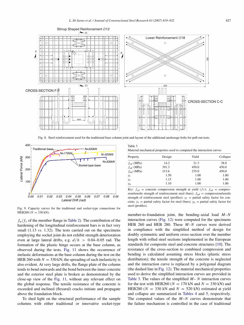
Fig. 8. Steel reinforcement used for the traditional base column joint and layout of the additional anchorage bolts for pull-out tests.
Fig. 9. Capacity curves for the traditional and socket-type connections forHEB260 (N = 330 kN).
fu/ fy of the member flange in Table 2). The contribution of thehardening of the longitudinal reinforcement bars is in fact verysmall (1.13 vs. 1.32). The tests carried out on the specimensemploying the socket joint do not exhibit strength deteriorationeven at large lateral drifts, e.g. d/h > 0.04–0.05 rad. Theformation of the plastic hinge occurs at the base column, asobserved during the tests. Fig. 11 shows the occurrence ofinelastic deformations at the base column during the test on theHEB 260 with N = 330 kN; the spreading of such inelasticity isalso evident. At very large drifts, the flange plate of the columntends to bend outwards and the bond between the inner concreteand the exterior steel plate is broken as demonstrated by theclose-up view of the Fig. 11, without any relevant effect onthe global response. The tensile resistance of the concrete isexceeded and inclined (flexural) cracks initiate and propagateabove the foundation block.
To shed light on the structural performance of the samplecolumns with either traditional or innovative socket-type
Table 3Material mechanical properties used to computed the interaction curves
Property Design Yield Collapse
fcd (MPa) 14.2 21.3 38.0fsd (MPa) 391.3 450.0 450.0fad (MPa) 213.6 235.0 450.0γc 1.50 1.00 1.00γs 1.15 1.00 1.00γa 1.10 1.00 1.00
Key: fcd = concrete compression strength at yield ( f c); fsd = compres-sion/tensile strength of reinforcement steel (bars); fad = compression/tensilestrength of reinforcement steel (profiles); γc = partial safety factor for con-crete; γs = partial safety factor for steel (bars); γa = partial safety factor forsteel (profiles).
member-to-foundation joint, the bending–axial load M–Ninteraction curves (Fig. 12) were computed for the specimensHEB 260 and HEB 280. These M–N curves were derivedin compliance with the simplified method of design fordoubly symmetric and uniform cross-section over the memberlength with rolled steel sections implemented in the Europeanstandards for composite steel and concrete structures [10]. Theresistance of the cross-section to combined compression andbending is calculated assuming stress blocks (plastic stressdistribution); the tensile strength of the concrete is neglectedand the interaction curve is replaced by a polygonal diagram(the dashed line in Fig. 12). The material mechanical propertiesused to derive the simplified interaction curves are provided inTable 3. The values of the simplified M– N interaction curvesfor the test with HEB260 (N = 170 kN and N = 330 kN) andHEB280 (N = 330 kN and N = 520 kN) estimated at yieldand collapse are summarized in Tables 4 and 5, respectively.The computed values of the M–N curves demonstrate thatthe failure mechanism is controlled in the case of traditional

828 L. Di Sarno et al. / Journal of Constructional Steel Research 63 (2007) 819–832
Fig. 10. Close-up view of the deformations of the specimen HEB260 with N = 330 kN (traditional connection).
Table 4Values of interaction curves for the test with HEB260 (N = 170 kN and N = 330 kN) and traditional joint at different performance state
Yield Collapse TestM (kN m) N (kN) M (kN m) N (kN) M (kN m) N (kN)
Section above stiffening plate 343 330 633 330 488 330339 170 628 170 433 170
Column base connection 440 330 550 330 596 330395 170 510 170 530 170
Table 5Values of interaction curves for the test with HEB280 (N = 330 kN andN = 520 kN) and socket-type joint at different performance state (at columnbase connection)
Yield Collapse TestM (kN m) N (kN) M (kN m) N (kN) M (kN m) N (kN)
390 330 740 330 608 330420 520 750 520 762 520
joint by the base column component. By contrast, for socket-type connections, the failure mode is due to the formation ofthe plastic hinges in the columns (see also Fig. 11, where thespreading of inelasticity due to flexure is evident).
The inelastic response of the critical region of the specimenswith socket-type joints was monitored carefully through six
electrical displacement transducers located at the column baseas displayed in Fig. 5. These LVDTs record the lateraldisplacement of several points of the column flanges inorder to define reliably the various inelastic phenomena,e.g. yielding, local buckling, fracture initiation, occurringat those locations during the tests. Fig. 13 provides force-rotation curves computed at the base column of the socket-type connection under monitonic loads. All monitored sectionsshows significant nonlinear response as the deformationsincrease; this behaviour characterizes also the cyclic tests [15].Comparison between total cord rotation and the base columnone derived from LVDT #6 measures enable to recognise thatthe higher is the drift, the higher is the contribution to the totaldrift given by the deformation of the socket type connection.Furthermore, due to the location of LVDT #1, 45.0 cm farfrom the foundation, the socket type shows a yielding spreading

L. Di Sarno et al. / Journal of Constructional Steel Research 63 (2007) 819–832 829
Fig. 11. Close-up view of the deformations of the specimen HEB260 with N = 330 kN (socket-type connection).
Fig. 12. Simplified interaction curve for combined axial load–uniaxial bendingmoment (N–M).
that is nearly twice the width of the section (45.0 cm vs.52.0 cm). As far as seismic design is concerned, the longerthe spreading of inelasticity the higher the energy dissipation.By contrast, traditional connection systems, employing boltedsteel end-plate generate high concentrated inelastic demand onthe anchorage bolts, which fail prematurely in a brittle manner.
Fig. 13. Force–rotation of the base column of the socket-type connection:LVDTs #1 to LVDT #6.
5. Numerical simulations
Numerical simulations of the pushover tests were carried outthrough a fibre-based model, which may accommodate both

830 L. Di Sarno et al. / Journal of Constructional Steel Research 63 (2007) 819–832
Fig. 14. Evaluation of fixed end rotation: system response (top-left), cross-section response (top-right) and computational model (bottom).
Fig. 15. Moment–curvature of the columns and the base joints: HEB260 with N = 330 kN (left) and N = 170 kN (right).
mechanical (material nonlinearity and residual stresses) andgeometrical (P–∆ effects) nonlinearities. The effects of thefixed end rotations are also accounted for; the computationalmodel is pictorially shown in Fig. 14. The constitutiverelationships employed in the numerical simulations werebased on experimental tests carried out on structural steeland reinforcement bars (see Table 2); concrete stress strainincluding size effect was used to simulate behaviour ofconcrete. The collapse of the sample columns was causedby base column joint failure in the case of the traditionalconnection as shown in Fig. 10. The ultimate resistance ofthe columns is thus controlled by this failure mechanism.Consequently, the ultimate bending moment of the base
joint was computed for purpose of comparisons. Themoment–curvature relationship of the base column was derivedthrough the constitutive relationship of anchorage bolts and theMander’s model for unconfined concrete for the high strengthmaterial which supports the rigid steel end-plate. The peakof resistance for concrete ( fc = 70 MPa) is assumed atεc = 0.002, which corresponds to the upper bound of thecompressive strength estimated via experimental tests. Theactual yield and ultimate strengths of the bolts are equal to400 MPa and 570 MPa, respectively; the strain hardeningstarts at εsh = 0.01. Fig. 15 provides the moment–curvaturecurves of the columns and the base joints for the samplespecimens HEB260 with both N = 170 kN and N = 330 kN.

L. Di Sarno et al. / Journal of Constructional Steel Research 63 (2007) 819–832 831
Fig. 16. Pull-out tests for anchorage bolts used for HEB260 with N = 330 kN (left) and N = 170 kN (right).
Reference lines relative to the onset of the yield in the basejoint and the column are also plotted in Fig. 15. For bothspecimens HEB 260, the former component yields at a value ofabout 300 kN m, while the column elastic threshold is higher(452 kN m and 475 kN m for HEB260 with N = 330 kNand N = 170 kN, respectively). The total deformation of thecolumns were computed by integrating the moment–curvaturealong the member. This relationship was derived by assumingthat member cross-sections remain plane and slip betweensteel and concrete does not take place (ideal bond); thecomputational model employed for the numerical simulationis outlined in Fig. 14. The fixed end rotation was estimatedthrough the moment–curvature of the base joint (position ofneutral axis) and a fitting curve of experimental bond-slipconstitutive relationships provided in Fig. 16 (slip effects).
Comparisons between numerical simulations and experi-mental test are provided in Fig. 17 for the sample column HEB260 with N = 330 kN; results for traditional and socket-typejoints are displayed. For the former, it may be observed that thevalue of the yield of the base joint is close to the elastic thresh-old measured during the experiment, thus demonstrating thatthe failure of the base column controls the global response ofthe composite steel and concrete column. This behaviour wasalso experienced by the sample HEB 260 with N = 170 kN.Force–deformation curves of the tested columns are also shownin the same figure. The total lateral deformations and the con-tributions caused by the fixed-end rotation and the column flex-ibility are included. The deformation of the column was esti-mated with respect to the length of 1310 mm, i.e. the distancebetween the column tip and the steel stiffening end plate atthe base. The comparison between experimental and numericalsimulation of the socket-type joint provided in Fig. 17 demon-strates that also for this type of connection layout the fixedend rotation can be significant. However, the contribution ofthe end rotation to the overall lateral displacement of the spec-imen with socket-type joint tends to be lower than in the caseof the traditional bolted base plate connection. The end rotationin the case of socket joints is caused by concrete–steel interfacemechanisms that occur within the socket, i.e. slip in the embed-ded length. This slip is a function of the concrete strength, thenumber and configuration of studs, if any, welded on the col-umn web. Moreover, for socket-type connections the bending
Fig. 17. Comparisons between numerical simulations and experimental test forHEB260 with N = 330 kN for traditional (H = 1310 mm) (top) and sockettype (H = 1700 mm) (bottom) joints.
moment computed through the numerical simulation of the can-tilever column with height of 1700 mm is smaller than the valueestimated experimentally; the difference between these bendingmoments is about 25%. Similarly, Fig. 17 shows that the yieldof the sample column evaluated numerically is higher than thatmeasured experimentally. The latter may be caused by the inter-action between the composite column and the surrounding con-crete. It is observed that for the socket type connection the fixityof the column is not located at the interface between the end-plate and the foundation block, but it penetrates in the socket,as proved by the profile of the lateral displacement determinedby means of the LVDTs shown in Fig. 5.
6. Conclusions
Experimental tests carried out on composite steel andconcrete columns were presented in this paper. Two layouts
832 L. Di Sarno et al. / Journal of Constructional Steel Research 63 (2007) 819–832
for the base column connections were assessed: the traditionalsystem employing the bolted steel end plate and the innovativesocket type. The experimental results demonstrate that thesocket system is beneficial for the spreading of inelasticityat the base of the composite columns. To assess theinelastic structural performance, the composite specimenswere subjected to monotonic loads at increasing lateral drifts(pushover experimental tests). It was found that the maximumdrift of the socket-type connection is nearly 75% higher than thetraditional bolted steel end plate. Traditional base connectionsfail in a less ductile fashion because of the fracture of theanchorage bolts. Conversely, socket connections exhibit aductile response due the formation of the plastic hinge at thebase of the column, which extends over a length much higherthan the cross section depth. As a result, socket-type joints canbe reliably used for design of structures which may experiencesignificant inelastic excursions, such as those in earthquakeprone regions.
Acknowledgements
The present work was funded by the Italian Ministryof Research, through the grant PRIN-COFIN04 (Compositesteel and concrete earthquake-resistant frames: advanceddissipative joint systems, methods for damage assessment andseismic design guidelines); the financial support is gratefullyacknowledged.
References
[1] Broderick BM, Elnashai AS. Seismic response of composite frames-I.Response criteria and input motion. Engineering Structures 1996;18(9):696–706.
[2] Byfield MP, Nethercot DA. Material and geometric properties ofstructural steel for use in design. The Structural Engineer, Journal of theInstitution of Structural Engineers 1997;75(21):363–7.
[3] Bursi OS, Caramelli S, Fabbrocino G, Molina J, Salvatore W, Taucer F.3D Full-scale seismic testing of a steel–concrete composite building atELSA. contr. no. HPR-CT-1999-00059. European Community; 2004.
[4] CNR 10016. Composite steel and concrete structures. Guidelines forapplications in construction. CNR bulletin n. 192. Rome (Italy); 1999 [inItalian].
[5] Cosenza E, Pecce MR. Le colonne composte acciaio-calcestruzzo: Analisisperimentali, modelli di calcolo, indicazioni normative. CostruzioniMetalliche 2001;10(2):49–60 [in Italian].
[6] Cosenza E, Zandonini R. Composite construction. In: Chen WF, editor.Handbook of structural engineering. Boca Raton (USA): CRC; 1997.
[7] Di Sarno L, Elnashai AS. Seismic retrofitting of steel and composite
building structures. Mid-America earthquake center report, CD Release02-01. IL (USA): University of Illinois at Urbana-Champaign; 2002.
[8] Eurocode 2. Design of concrete structures. Part 1.1: General rules andrules for buildings. Brussels (Belgium): Eur. Comm. for Stand.; 2004.
[9] Eurocode 3. Design of steel structures. Part 1.1: General rules and rulesfor buildings. Brussels (Belgium): Eur. Comm. for Stand.; 2004.
[10] Eurocode 4. Design of composite steel and concrete structures. Part 1.1:General rules and rules for buildings. Brussels (Belgium): Eur. Comm. forStand.; 2004.
[11] Eurocode 8. Design provisions for earthquake resistance of structures.Part 1.3: General rules. Specific rules for various materials and elements.Brussels (Belgium): Eur. Comm. for Stand; 2004.
[12] Elnashai AS, Elghazouli Y. Performance of composite steel–concretemembers under earthquake loading, part 2: Parametric studies and designconsiderations. Earthquake Engineering and Structural Dynamics 1993;22(4):347–68.
[13] Fabbrocino G, Manfredi G, Cosenza E, Pecce MR. Some remarks ondeformation capacity of composite frames in seismic areas. In: Proc. ofthe 1st international conference on steel and composite structures. 2001.
[14] Fabbrocino G, Pecce MR, Di Sarno L. Inelastic response of steel andconcrete columns. In: Proc. of the fourth international conference on steeland composite structures. 2004. CD-ROM.
[15] Fabbrocino G, Pecce MR, Di Sarno L. Inelastic response of steel andconcrete columns. In: Proc. of the fourth international conference onadvances in steel sructures. vol. I. 2005. p. 793–8.
[16] Federal Emergency Management Agency. Prestandard and commentaryfor the seismic rehabilitation of buildings. FEMA report no. 356.Washington DC (USA); 2000.
[17] Hajjar JF. Composite steel and concrete structural systems for seismicengineering. Journal of Constructional Steel Research 2002;58(5–8):702–23.
[18] Lee TKL, Pan ADE. Analysis of composite beam–columns under lateralcyclic loading. Journal of Structural Engineering, ASCE 2001;127(2):186–93.
[19] Mazzolani FM. Steel and composite structures in European seismic areas:Research, codification, design and applications. Earthquake Spectra 2003;19(2):415–52.
[20] OPCM. General criteria for new seismic zonation in Italy and seismicstandards. Rome (Italy): Department of National Emergency Agency;2003 [in Italian].
[21] Ricles JM, Paboojian SD. Seismic performance of steel-encasedcomposite columns. Journal of Structural Engineering, ASCE 1994;120(8):2474–94.
[22] Roeder CW. Overview of hybrid and composite systems for seismicdesign in the United States. Engineering Structures 1998;20(4–6):355–63.
[23] Shanmugam NE, Lakshmi B. State of art report on steel–concretecomposite columns. Journal of Constructional Steel Research 2001;57(10):1041–80.
[24] Spacone E, El-Tawil S. Nonlinear analysis of steel–concrete compositestructures: State of the art. Journal of Structural Engineering, ASCE 2004;130(2):159–68.
[25] Thermou GE, Elnashai AS, Plumier A, Doneux C. Seismic designand performance of composite frames. Journal of Constructional SteelResearch 2004;60(1):31–57.