Industry Report STRUCTURAL STEELWORK · 2016-11-08 · 400t of Westok cellular beams. “We worked...
11
P66 FRIARGATE: HIGH QUALITY, LOW CARBON P68 GREEN PORT TURBINE FACTORY, HULL P70 NEW VIBRATION GUIDE P72 STEEL BOOSTS SQUARE FOOTAGE P74 FLEXIBILITY FOR GREENWICH ENERGY FACILITY Steel for Life would like to thank its sponsors: HEADLINE GOLD AJN Steelstock, Ficep UK, Kingspan Limited, National Tube Stockholders and Cleveland Steel & Tubes, ParkerSteel, Peddinghaus Corporation, voestalpine Metsec, Wedge Group Galvanizing SILVER Hadley Group Building Products Division, Jack Tighe ● For further information about steel construction and Steel for Life, please visit www.steelconstruction.info or www.steelforlife.org Edited and written by Martin Cooper Industry Report STRUCTURAL STEELWORK IN ACTION BARRETT STEEL LIMITED
Transcript of Industry Report STRUCTURAL STEELWORK · 2016-11-08 · 400t of Westok cellular beams. “We worked...
P66 FRIARGATE: HIGH QUALITY, LOW CARBON P68 GREEN PORT TURBINE FACTORY, HULLP70 NEW VIBRATION GUIDE P72 STEEL BOOSTS SQUARE FOOTAGE P74 FLEXIBILITY FOR GREENWICH ENERGY FACILITY
Steel for Life would like to thank its sponsors:
HEADLINE
GOLD AJN Steelstock, Ficep UK, Kingspan Limited, National Tube Stockholders and Cleveland Steel & Tubes, ParkerSteel, Peddinghaus Corporation, voestalpine Metsec, Wedge Group Galvanizing
SILVERHadley Group Building Products Division, Jack Tighe
� For further information about steel construction and Steel for Life, please visit www.steelconstruction.info or www.steelforlife.org
Edited and written by Martin Cooper
Industry Report STRUCTURAL STEELWORK IN ACTION
BARRETTSTEEL LIMITED

SOLIDSOLUTION11 STOREY STEEL-FRAMED DEVELOPMENT FOR COVENTRY SITE
Over the coming years, a large 14.4ha swathe of Coventry city centre will be transformed as the Friargate regeneration project progresses. The fi rst building in this scheme – a new offi ce for the local council – is under way, with a second offi ce block due
to start very soon (see box).The Friargate vision is to deliver a high quality, low carbon
development that generates jobs and attracts investment. Situated opposite Coventry railway station, the mixed-use offi ce-led development will also encompass residential blocks and a hotel, creating a new city gateway.
Steelwork is likely to play a signifi cant part in the construction of Friargate, beginning with Building One, which is an 11-storey steel-framed offi ce block to be occupied by Coventry City Council.
Prior to work starting on this initial structure, main contractor Bowmer & Kirkland spent nearly nine months on site demolishing existing buildings to make space for the new building, creating new footpaths and doing service diversions.
Known as Project Heron, Building One is constructed around a slightly offset slipformed concrete core, with the steel composite frame supporting 150mm-thick decks, sitting atop a ground fl oor transfer slab that spans a two-level basement.
No internal bracing systems are necessary as all of the steel frame’s stability is derived from the core.
Perimeter columns are spaced at 9m centres, while internal spans are up to 12m long, creating a mostly column-free environment for the majority of the building’s fl oorplate.
Bowmer & Kirkland project manager Paul Kelly says: “The design for this building is steel-framed as it is a quicker, and a
Key fact
1 ,000tAmount of structural steel used
more effi cient method of creating the required long spans.”Capita project engineer Dave Middleton agrees and says: “Early in the design phase we undertook a comparative
study which looked at a number of framing options. The optimum solution, which met the the architectural and services requirements in the most cost-effective manner was found to be a steel frame with cellular beams.
“Working on behalf of main contractor Bowmer & Kirkland, Hambleton Steel has erected approximately 1,000t of structural steelwork for the project, a total that includes 400t of Westok cellular beams.
“We worked in conjunction with Hambleton Steel to develop the most cost-effective cellular beam solution for the building, says Kloeckner Westok design team leader John Callanan.
“This is another example of the type and scale of modern Grade A offi ce development we continue to see across the UK and Ireland, where the structure and service solution work hand-in-hand to deliver a fl exible and cost-
STRUCTURAL STEELWORK IN ACTION
66 N E W C I V I L E N G I N E E R | D E C E M B E R 2016
B Y M A R T I N C O O P E R
“We worked in conjunction
with Hambleton Steel to develop the most cost-e� ective cellular beam solution

effective floorplate. “Clients demand open, flexible, clear span office
structures which are speedy to erect, and cellular steelwork hits the mark by integrating the service requirements of today, while at the same time providing the requisite future-proofing to safeguard against late design changes and differing future tenant service requirements.
“A continuous string of cells within the beam is the most cost-effective means to achieve this. We worked closely with Hambleton Steel to value engineer the floorplate and discrete 400m by 700mm elongated cells were provided in the Westok floor beams to allow large rectangular ducts to pass where needed. These compliment the string of 400mm diameter cells provided in each beam.”
Steelwork was completed during a 12-week programme, with Hambleton initially using two mobile cranes and mobile elevating work platforms, positioned on the ground floor slab, to erect up to level six.
Once the steel metal decking had begun to be installed,
Coventry City Council has recently approved the second building in the Friargate development. Sitting alongside Building One it has a similar steel-framed design with floorplates of 1,000m2.
The 14-storey office will have a double-height ground floor that will provide leisure space for a restaurant or café, and a seventh floor terrace.
Stephen Reynolds of Friargate Coventry said: “We are pleased to have secured consent for the second building, having worked closely with the council throughout the planning process.
The masterplan is now beginning to redefine the urban landscape linking the station with the city centre.”
According to project architect Allies & Morrison, the masterplan for Coventry Friargate will re-establish a straightforward and direct connection between the railway station and the city centre.
A new public square will be created in front of the Grade II listed station and Warwick Road will be transformed into a tree-lined boulevard with a public transport interchange close to the station.The mixed-use scheme will provide high quality office buildings, with restaurants and shops at ground level. Hotels, leisure and community uses are also planned, with housing located in the quieter areas to the east and west of the central quarter.
SECOND STEEL FRAME TO START SOON
FRIARGATE MASTERPLAN
67D E C E M B E R 2016 | N E W C I V I L E N G I N E E R
the upper floors were erected using the site’s two tower cranes supplemented by deck rider access equipment positioned on the decked levels.
Offering a spacious entrance lobby and areas for possible retail units, the building features a double-height ground floor area. This is formed with 356UC perimeter columns that decrease in size as the building rises.
“Large section sizes were required, as the steel frame is working hard supporting the cladding, which is a panelised brickwork system with panels weighing up to 12t each,” says Kelly.
Offering breakout space for the office workers, the uppermost level of the building steps back on all sides to form a terrace.
Ready for occupation next year, the building will accommodate many of the council’s office-based staff. Coventry City Council leader councillor Ann Lucas says: “This first building sets the standard, and as we want to be a top 10 city again, developments like this will help us get there.”
Project : Friargate Building One, CoventryMain c l ient : Friargate CoventryArchitect : Allies & MorrisonMain contractor : Bowmer & KirklandStructural engineer : CapitaSteelwork contractor : Hambleton Steel
PROJECT TEAM
Cutting EdgESiEmEnS buildS StEEl-framEd faCtory in Hull for wind turbinE bladES
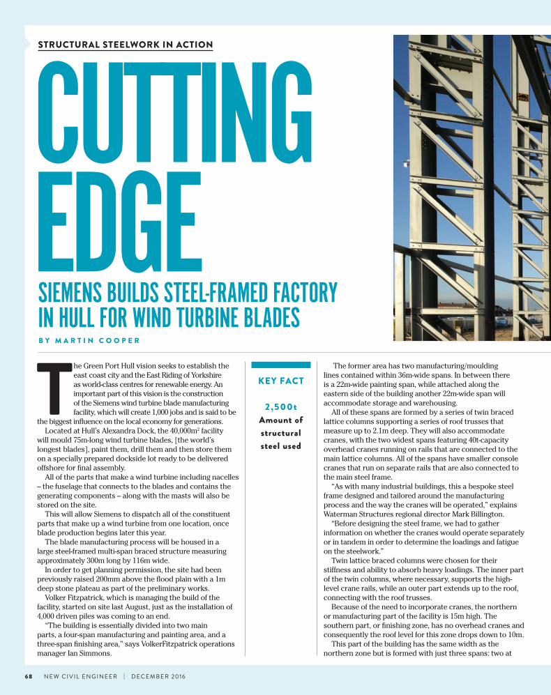
The Green Port Hull vision seeks to establish the east coast city and the East Riding of Yorkshire as world-class centres for renewable energy. An important part of this vision is the construction of the Siemens wind turbine blade manufacturing facility, which will create 1,000 jobs and is said to be
the biggest influence on the local economy for generations.Located at Hull’s Alexandra Dock, the 40,000m2 facility
will mould 75m-long wind turbine blades, [the world’s longest blades], paint them, drill them and then store them on a specially prepared dockside lot ready to be delivered offshore for final assembly.
All of the parts that make a wind turbine including nacelles – the fuselage that connects to the blades and contains the generating components – along with the masts will also be stored on the site.
This will allow Siemens to dispatch all of the constituent parts that make up a wind turbine from one location, once blade production begins later this year.
The blade manufacturing process will be housed in a large steel-framed multi-span braced structure measuring approximately 300m long by 116m wide.
In order to get planning permission, the site had been previously raised 200mm above the flood plain with a 1m deep stone plateau as part of the preliminary works.
Volker Fitzpatrick, which is managing the build of the facility, started on site last August, just as the installation of 4,000 driven piles was coming to an end.
“The building is essentially divided into two main parts, a four-span manufacturing and painting area, and a three-span finishing area,” says VolkerFitzpatrick operations manager Ian Simmons.
KEY FACT
2,500tAmount of structural steel used
The former area has two manufacturing/moulding lines contained within 36m-wide spans. In between there is a 22m-wide painting span, while attached along the eastern side of the building another 22m-wide span will accommodate storage and warehousing.
All of these spans are formed by a series of twin braced lattice columns supporting a series of roof trusses that measure up to 2.1m deep. They will also accommodate cranes, with the two widest spans featuring 40t-capacity overhead cranes running on rails that are connected to the main lattice columns. All of the spans have smaller console cranes that run on separate rails that are also connected to the main steel frame.
“As with many industrial buildings, this a bespoke steel frame designed and tailored around the manufacturing process and the way the cranes will be operated,” explains Waterman Structures regional director Mark Billington.
“Before designing the steel frame, we had to gather information on whether the cranes would operate separately or in tandem in order to determine the loadings and fatigue on the steelwork.”
Twin lattice braced columns were chosen for their stiffness and ability to absorb heavy loadings. The inner part of the twin columns, where necessary, supports the high-level crane rails, while an outer part extends up to the roof, connecting with the roof trusses.
Because of the need to incorporate cranes, the northern or manufacturing part of the facility is 15m high. The southern part, or finishing zone, has no overhead cranes and consequently the roof level for this zone drops down to 10m.
This part of the building has the same width as the northern zone but is formed with just three spans: two at
STRUCTURAL STEELWORK IN ACTION
68 N E W C I V I L E N G I N E E R | D E C E M B E R 2016
B Y M A R T I N C O O P E R

47m and a third measuring 22m wide. As this area does not have to support any cranes, the truss supporting columns are not twin lattice sections but 610 UBs.
“The longest trusses were brought to site in three sections, while the 22m-long trusses were fabricated in two pieces,” explains Caunton Engineering contract manager Michael Firth. “Once on site they were bolted and assembled into complete trusses and then lifted into place by a single mobile crane.”
Caunton Engineering had up to five mobile cranes working on its steel programme, with multiple spans of the building being erected at any one time.
The facility also features a two-storey office block that is structurally independent as it gains its stability not from bracing but from a series of moment frames. It features a steel frame supporting precast planks on the beam’s bottom flange, a construction method chosen as the client wanted exposed soffits.
The first wind farm to receive turbines from the Hull facility later this year is expected to be Dudgeon, which is located off the Norfolk coast.
Associated British Ports, which owns the site, has appointed Graham Lagan Construction Group JV to develop the overall Alexandra Dock for the Siemens facilities.
The blade manufacturing facility is being built under a separate contract and so all around this site other important works are ongoing.
The JV is responsible for the partial reclamation and infill of the existing dock, the construction of three new berths and a roll-on, roll-off ramp.
On the opposite side of the dock to the blade facility, a separate steel-framed structure for the servicing and refurbishment of blades is being erected.
Project : Siemens wind turbine blade manufacturing facility, HullMain c l ient : SiemensArchitect : Pringle Brandon Perkins + WillMain contractor : VolkerFitzpatrickStructural engineer : Waterman StructuresSteelwork contractor : Caunton Engineering
ALEXANDRA DOCK: THE WHOLE STORY
PROJECT TEAM
“ The longest trusses were brought to site in three
sections, while the 22m-long trusses were fabricated in two pieces
The facility has a high roof to accommodate gantry cranes
69D E C E M B E R 2016 | N E W C I V I L E N G I N E E R
Computer rendering of the turbine blades factory
STEEL DELIVERS THE REQUIRED VIBRATION PERFORMANCE FOR MULTI-STOREY BUILDINGS
T here has been an increase in demand for buildings that are fast to construct, have large uninterrupted fl oor areas and are fl exible in their intended fi nal use. Modern design and construction techniques enable steel construction to satisfy these demands and deliver
structures, which are competitive in terms of overall cost.When it comes to long-span applications, most
commonly found in commercial projects, good dynamic performance is the norm, despite some preconceptions that steel composite fl oors are livelier than concrete ones.
The reason for this good performance is because the stiffer beams and large mass of the long-span fl oorplates, which participates in any motion, reduce the magnitude of the vibration response. The steel sector has extensive experience in designing steel structures to ensure compliance with even the strictest vibration performance criteria.
To help designers in the steel construction sector, new vibration and design guidance that lays to rest misconceptions about the dynamic performance of steel-framed structures is available.
The guidance is entitled Steel Construction: Floor Vibration and it summarises the issue of fl oor dynamics and what the designer should do to confi rm there are no problems.
The guide provides an overview of the dynamic behaviour of fl oors, the acceptance criteria commonly
adopted and, importantly, the techniques for actually calculating the fl oor response.
Traditionally, a very basic approach was taken to calculate the natural frequency of a fl oor based on defl ection and to avoid resonance with walking activity. Up-to-date assessment requires the calculation of a response factor, with different limits appropriate for different environments, such as offi ces, bedrooms,
hospitals etc.The calculation of the fl oor response is complex,
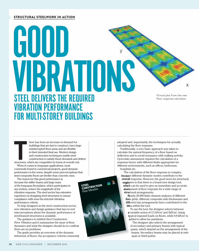
because different dynamic modes contribute to the overall response. However, the good news for structural engineers is that there is a brand new design tool, which can be used to give an immediate and accurate assessment of fl oor response for a wide range of structural arrangements.
Nearly 20,000 fi nite element analyses of different fl oor grids, different composite slab thicknesses and different bay arrangements have contributed to the data within the tool.
To use the tool, the designer selects between a variable action of 2.5 kN/m2 and 5kN/m2, being typical imposed loads on fl oors, while 0.8 kN/m2 is added to allow for partitions.
The designer also selects the arrangement of secondary and primary beams with typical spans, which depend on the arrangement of the beams. Secondary beams may be placed at mid-span or third points.
GOOD VIBRATIONS
STRUCTURAL STEELWORK IN ACTION
70 N E W C I V I L E N G I N E E R | D E C E M B E R 2016
dynamics and what the designer should do to confi rm
behaviour of fl oors, the acceptance criteria commonly
because different dynamic modes contribute to the overall response. However, the good news for structural engineers is that there is a brand new design tool, which can be used to give an immediate and accurate assessment of fl oor response for a wide range of structural arrangements.
Nearly 20,000 fi nite element analyses of different fl oor grids, different composite slab thicknesses and different bay arrangements have contributed to the data within the tool.
a variable action of 2.5 kN/mtypical imposed loads on fl oors, while 0.8 kN/madded to allow for partitions.
Virtual plot from the new floor response calculator

Creechurch Place is a 19-storey T-shaped office development being built in the City of London. The aim of the project is to deliver a new, modern, flexible and efficient office building of the highest quality.
The structure will comprise two levels of basement, ground floor and 17 upper levels, plus rooftop plant, all providing 25,350m2 of flexible Grade A commercial office space and 284m2 of retail/café space. The design
for the majority of the tower was always a steel building as the material enables the structure to have long clear spans, which would not have been possible with concrete.
The steel frame is based around a regular grid offering open-plan office space with column-free spans of up to 16.5m-long. Only two internal columns are present throughout the entire structure.
Steel contractor William Hare has installed cellular beams throughout the majority of the structural frame to allow
the building’s services to be accommodated within the structural void.
Despite the long spans, the use of cellular beams was not an issue for the floor vibrations.
Ramboll used its experience of in-situ testing to demonstrate that through careful consideration of the layout and interactions between the cellular beams, they could still be used efficiently, without having to adopt the more traditional method of using heavier beams to increase the stiffness.
C R E E C H U R C H P L A C E
Computer visualisation of the Collaboration Space building
The pre-set damping ratio of 3% is recommended for furnished floors in normal use. When a decking profile is chosen, an appropriate range of slab depths is then available to be selected.
The primary and secondary beams are selected automatically from the UB range (grade S355) as the lightest sections, which satisfy strength and deflection requirements. The selection of the lightest sections is made to produce the most conservative dynamic response, as stiffer beams will reduce the response.
A visual plot of the response is also provided for the steady state and transient response. Hovering over the plotting points shows the response factor.
Although there are clearly infinite permutations of spans,
71D E C E M B E R 2016 | N E W C I V I L E N G I N E E R
layout, beam sizes, slabs, etcetera, if the proposed solution differs from the pre-set arrangements in the tool, the designer simply has to recognise that stiffer beams than assumed will reduce the response, as will using thicker slabs (with corresponding stiffer beams).
The new guide and the on-line design tool provide the background and the practical implementation of what would otherwise be a complicated and time-consuming assessment. By using these, engineers will find it straightforward to demonstrate that a proposed floor solution will have a satisfactory response.
The guide and web-based floor response calculator are freely available at www.steelconstruction.info
SPACE PLACESTEEL FRAME BOOSTS SQUARE FOOTAGE FOR CITY DEVELOPMENT
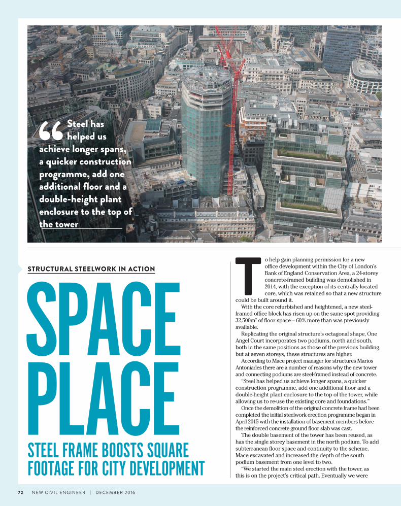
T o help gain planning permission for a new offi ce development within the City of London’s Bank of England Conservation Area, a 24-storey concrete-framed building was demolished in 2014, with the exception of its centrally located core, which was retained so that a new structure
could be built around it. With the core refurbished and heightened, a new steel-
framed offi ce block has risen up on the same spot providing 32,500m2 of fl oor space – 60% more than was previously available.
Replicating the original structure’s octagonal shape, One Angel Court incorporates two podiums, north and south, both in the same positions as those of the previous building, but at seven storeys, these structures are higher.
According to Mace project manager for structures Marios Antoniades there are a number of reasons why the new tower and connecting podiums are steel-framed instead of concrete.
“Steel has helped us achieve longer spans, a quicker construction programme, add one additional fl oor and a double-height plant enclosure to the top of the tower, while allowing us to re-use the existing core and foundations.”
Once the demolition of the original concrete frame had been completed the initial steelwork erection programme began in April 2015 with the installation of basement members before the reinforced concrete ground fl oor slab was cast.
The double basement of the tower has been reused, as has the single storey basement in the north podium. To add subterranean fl oor space and continuity to the scheme, Mace excavated and increased the depth of the south podium basement from one level to two.
“We started the main steel erection with the tower, as this is on the project’s critical path. Eventually we were
STRUCTURAL STEELWORK IN ACTION
“ Steel has helped us
achieve longer spans, a quicker construction programme, add one additional fl oor and a double-height plant enclosure to the top of the tower
72 N E W C I V I L E N G I N E E R | D E C E M B E R 2016

Open-plan office space continues from the tower into the two adjoining podiums, which have spans up to 17m long. While the tower’s beams are shallow UB sections installed to maximise the structure’s floor-to-ceiling heights, the podiums have been formed with a series of Fabsec cellular members erected around centrally-positioned slipformed cores.
“With the long spans we wanted to achieve in the podiums, cellular beams were chosen as UB sections of that length would have been too heavy,” says Bergbaum. “As we are reusing the foundations, it was important to make the steel frame as light as possible.”
To aid the construction programme, the podiums’ perimeter beams and columns were all concrete-encased prior to arriving on site.
As the podiums reach a maximum of seven-storeys high, and in order to avert the need to splice the members, the perimeter columns were delivered and erected in lengths of up to 19m, weighing just under 10t each.
The most visually outstanding feature of the podium are the terraces, formed with steps in the steel frame at levels three, four and five, and the rooftop gardens.
A series of 11t, 500mm-deep fabricated beams were installed throughout both of the podiums to form these terraces.
The main entrance for the scheme is via a double-height space set back along the western elevation. This faces Angel Court, a previously narrow and dark passageway linking Copthall Avenue with Throgmorton Street.
According to Fletcher Priest Architects, the development has added 30% to the public realm, turning Angel Court into an attractive pedestrian street lined with shops and restaurants, which catch midday sun, rather than a dark alleyway reached through a hole in the wall.
The project is due to be finished by the end of this year.
KEY FACT
3,900tAmount of structural steel used
working on three fronts once the podiums started,” explains Severfield senior project manager David Managh.
From ground floor up to seventh floor, the tower’s columns are inclined, before straightening up for the upper floors. This means for the uppermost 17 levels, the tower is approximately 3m wider than the original building thereby increasing its available floor space.
The tower features 9m clear spans from the centrally positioned core to the perimeter steelwork. Supporting composite metal decking, the radial beams are 254UBs, while the perimeter members are slightly larger 525UBs.
Using a refurbished core within the tower presented a steel erection challenge.
“Each floor had to be thoroughly surveyed prior to the steelwork being installed as the fixing plates were in slightly varying positions on each level, because it was important to miss the core’s rebar when they were put in place,” says Managh. “So although the beams are in the same arrangement, each floor is slightly different.”
Topping the tower is a steel structure known as the “birds nest”, which spans the roof plant deck at level 27. To allow construction of this roof and level 26, which is another plant deck, the core was heightened with the addition of a three-storey steel framework.
“The original concept for the roof enclosure would have involved a very high piece count, so to speed up the construction schedule the birds nest was designed as a light and slender steel frame, stabilised by the core and,importantly, prefabricated offsite in large sections,” says Waterman regional director Edwin Bergbaum.
Spanning around and over the roof of the tower, the birds nest steelwork was prefabricated as a series of galvanized two dimensional trusses measuring 3m deep and up to 18m long.
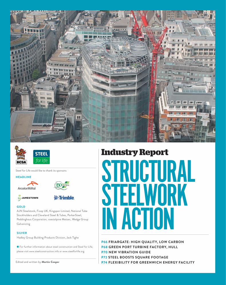
Left: The steel frame was built around an existing concrete coreFar right: Artists impression of the completed building
Project : One Angel Court, LondonMain c l ient : Stanhope/Mitsui Fudosan UKArchitect : Fletcher Priest ArchitectsConstruct ion manager : MaceStructural engineer : Waterman StructuresSteelwork contractor : Severfield
PROJECT TEAM
73D E C E M B E R 2016 | N E W C I V I L E N G I N E E R
POwer PrOviderSteel Structure giveS NOrth greeNwich eNergy facility maximum flexibility
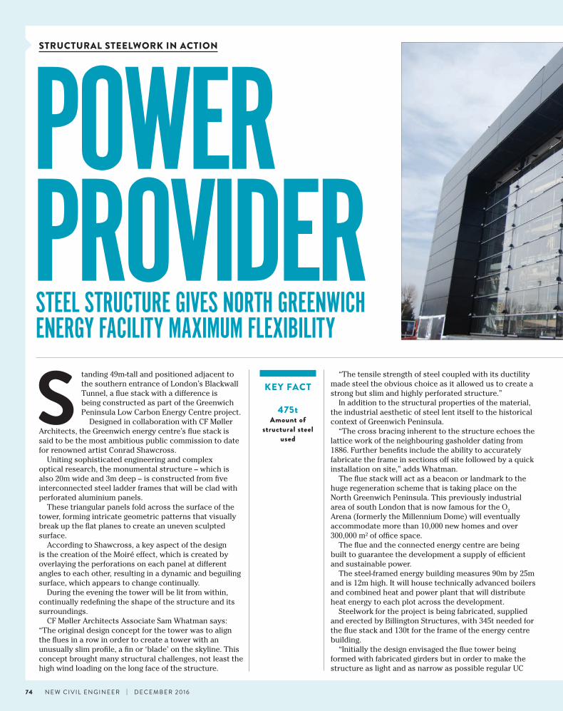
S tanding 49m-tall and positioned adjacent to the southern entrance of London’s Blackwall Tunnel, a flue stack with a difference is being constructed as part of the Greenwich Peninsula Low Carbon Energy Centre project.
Designed in collaboration with CF Møller Architects, the Greenwich energy centre’s flue stack is said to be the most ambitious public commission to date for renowned artist Conrad Shawcross.
Uniting sophisticated engineering and complex optical research, the monumental structure – which is also 20m wide and 3m deep – is constructed from five interconnected steel ladder frames that will be clad with perforated aluminium panels.
These triangular panels fold across the surface of the tower, forming intricate geometric patterns that visually break up the flat planes to create an uneven sculpted surface.
According to Shawcross, a key aspect of the design is the creation of the Moiré effect, which is created by overlaying the perforations on each panel at different angles to each other, resulting in a dynamic and beguiling surface, which appears to change continually.
During the evening the tower will be lit from within, continually redefining the shape of the structure and its surroundings.
CF Møller Architects Associate Sam Whatman says: “The original design concept for the tower was to align the flues in a row in order to create a tower with an unusually slim profile, a fin or ‘blade’ on the skyline. This concept brought many structural challenges, not least the high wind loading on the long face of the structure.
“The tensile strength of steel coupled with its ductility made steel the obvious choice as it allowed us to create a strong but slim and highly perforated structure.”
In addition to the structural properties of the material, the industrial aesthetic of steel lent itself to the historical context of Greenwich Peninsula.
“The cross bracing inherent to the structure echoes the lattice work of the neighbouring gasholder dating from 1886. Further benefits include the ability to accurately fabricate the frame in sections off site followed by a quick installation on site,” adds Whatman.
The flue stack will act as a beacon or landmark to the huge regeneration scheme that is taking place on the North Greenwich Peninsula. This previously industrial area of south London that is now famous for the O2 Arena (formerly the Millennium Dome) will eventually accommodate more than 10,000 new homes and over 300,000 m² of office space.
The flue and the connected energy centre are being built to guarantee the development a supply of efficient and sustainable power.
The steel-framed energy building measures 90m by 25m and is 12m high. It will house technically advanced boilers and combined heat and power plant that will distribute heat energy to each plot across the development.
Steelwork for the project is being fabricated, supplied and erected by Billington Structures, with 345t needed for the flue stack and 130t for the frame of the energy centre building.
“Initially the design envisaged the flue tower being formed with fabricated girders but in order to make the structure as light and as narrow as possible regular UC
KEY FACT
475tAmount of
structural steel used
STRUCTURAL STEELWORK IN ACTION
74 N E W C I V I L E N G I N E E R | D E C E M B E R 2016
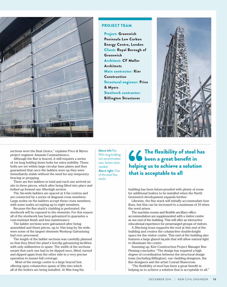
sections were the final choice,” explains Price & Myers project engineer Amanda Constantinesco.
Although the flue is braced, it still requires a series of 1m long holding down bolts for extra stability. These bolts are set within large circular base plates and they guaranteed that once the ladders were up they were immediately stable without the need for any temporary bracing or propping.
There are five ladders in total and each one arrived on site in three pieces, which after being lifted into place and bolted up formed one 49m-high section.
The 3m-wide ladders are spaced at 4.5m centres and are connected by a series of diagonal cross members. Large nodes on the ladders accept these cross members, with some nodes accepting up to eight members.
Because the flue stack’s cladding is perforated, the steelwork will be exposed to the elements. For this reason all of the steelwork has been galvanized to guarantee a rust-resistant finish and less maintenance.
The ladder sections were galvanized after being assembled and these pieces, up to 16m long by 3m wide, were some of the largest elements Worksop Galvanizing had ever processed.
The length of the ladder sections was carefully planned so that they fitted the plant’s hot-dip galvanizing facilities with only millimetres to spare. The width of the sections meant that each one had to be dipped once, lifted, turned and dipped again from the other side in a very precise operation to ensure full coverage.
Most of the energy centre is a large braced box offering open column-free spans of 20m into which all of the boilers are being installed. At 90m long the
Project: Greenwich Peninsula Low Carbon Energy Centre, LondonClient: Royal Borough of GreenwichArchitect: CF Møller ArchitectsMain contractor: Kier Construction Structural engineer: Price & MyersSteelwork contractor: Billington Structures
PROJECT TEAM
Above left:The 90m long building can accommodate exta boilers when needed.Above right: One of the steel flue stacks
building has been future-proofed with plenty of room for additional boilers to be installed when the North Greenwich development expands further.
Likewise, the flue stack will initially accommodate four flues, but this can be increased to a maximum of 10 when the need arises.
The machine rooms and flexible ancillary office accommodation are supplemented with a visitor centre at one end of the building. This will offer an interactive educational experience for prearranged groups of visitors.
A 20m-long truss supports the roof at this end of the building and creates the column-free double-height space for the visitor centre. This end of the building also features a large glazed façade that will allow natural light to illuminate the centre.
Summing up, Kier Construction Project Manager Ben Fleming concludes: “The design has required a high degree of co-ordination between the structural design team (including Billington), our cladding designers, the flue designers and the artist Conrad Shawcross.
“The flexibility of steel has been a great benefit in helping us to achieve a solution that is acceptable to all.”
“The flexibility of steel has been a great benefit in
helping us to achieve a solution that is acceptable to all
75D E C E M B E R 2016 | N E W C I V I L E N G I N E E R