Industrial Upscaling of Electrospinning and Applications...
17
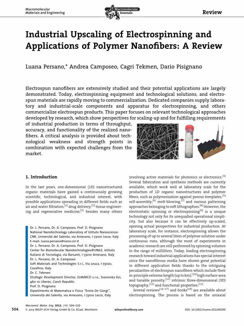
Industrial Upscaling of Electrospinning and Applications of Polymer Nanofibers: A Review Luana Persano,* Andrea Camposeo, Cagri Tekmen, Dario Pisignano 1. Introduction In the last years, one-dimensional (1D) nanostructured organic materials have gained a continuously growing scientific, technological, and industrial interest, with possible applications spreading in different fields such as air and water filtration, [1] drug delivery, [2] tissue engineer- ing and regenerative medicine, [3] besides many others involving active materials for photonics or electronics. [4] Several fabrication and synthesis methods are currently available, which work well at laboratory scale for the production of 1D organic nanostructures and polymer fibers, such as polymerization against porous templates, [5] self-assembly, [6] melt-blowing, [7] and various patterning approaches belonging to soft lithographies. [8] However, the electrostatic spinning or electrospinning [9] is a unique technology not only for its unequalled operational simpli- city, but also because it can be effectively up-scaled, opening actual perspectives for industrial production. At laboratory scale, for instance, electrospinning allows the processing of up to several liters of polymer solution under continuous runs, although the most of experiments in academic research are still performed by spinning volumes in the range of milliliters. Today, leading electrospinning research toward industrial applications has special interest since the nanofibrous media have shown great potential in different application fields thanks to the intriguing peculiarities of electrospun nanofibers which include their in-principle extreme length (up to km), [10] high surface-area and tunable porosity, [11] intrinsic three-dimensional (3D) topography, [12] and functional properties. [13] Several reviews [14–17] and books [18] are available about electrospinning. The process is based on the uniaxial Review Dr. L. Persano, Dr. A. Camposeo, Prof. D. Pisignano National Nanotechnology Laboratory of Istituto Nanoscienze- CNR, Universita ` del Salento, via Arnesano, I-73100 Lecce, Italy E-mail: [email protected] Dr. L. Persano, Dr. A. Camposeo, Prof. D. Pisignano Center for Biomolecular Nanotechnologies@UNILE, Istituto Italiano di Tecnologia, via Barsanti, I-73010 Arnesano, Italy Dr. L. Persano, Dr. A. Camposeo Soft Materials and Technologies S.r.l., Via Leuca, I-73020, Cavallino, Italy Dr. C. Tekmen Strategic Development Director, ELMARCO s.r.o., Svarovska 621, 460 10 Liberec, Czech Republic Prof. D. Pisignano Dipartimento di Matematica e Fisica ‘‘Ennio De Giorgi’’, Universita ` del Salento, via Arnesano, I-73100 Lecce, Italy Electrospun nanofibers are extensively studied and their potential applications are largely demonstrated. Today, electrospinning equipment and technological solutions, and electro- spun materials are rapidly moving to commercialization. Dedicated companies supply labora- tory and industrial-scale components and apparatus for electrospinning, and others commercialize electrospun products. This paper focuses on relevant technological approaches developed by research, which show perspectives for scaling-up and for fulfilling requirements of industrial production in terms of throughput, accuracy, and functionality of the realized nano- fibers. A critical analysis is provided about tech- nological weakness and strength points in combination with expected challenges from the market. 504 Macromol. Mater. Eng. 2013, 298, 504–520 ß 2013 WILEY-VCH Verlag GmbH & Co. KGaA, Weinheim wileyonlinelibrary.com DOI: 10.1002/mame.201200290
Transcript of Industrial Upscaling of Electrospinning and Applications...
Review
504
Industrial Upscaling of Electrospinning andApplications of Polymer Nanofibers: A Review
Luana Persano,* Andrea Camposeo, Cagri Tekmen, Dario Pisignano
Electrospun nanofibers are extensively studied and their potential applications are largelydemonstrated. Today, electrospinning equipment and technological solutions, and electro-spun materials are rapidly moving to commercialization. Dedicated companies supply labora-tory and industrial-scale components and apparatus for electrospinning, and otherscommercialize electrospun products. This paper focuses on relevant technological approachesdeveloped by research, which show perspectives for scaling-up and for fulfilling requirementsof industrial production in terms of throughput,accuracy, and functionality of the realized nano-fibers. A critical analysis is provided about tech-nological weakness and strength points incombination with expected challenges from themarket.
1. Introduction
In the last years, one-dimensional (1D) nanostructured
organic materials have gained a continuously growing
scientific, technological, and industrial interest, with
possible applications spreading in different fields such as
air and water filtration,[1] drug delivery,[2] tissue engineer-
ing and regenerative medicine,[3] besides many others
Dr. L. Persano, Dr. A. Camposeo, Prof. D. PisignanoNational Nanotechnology Laboratory of Istituto Nanoscienze-CNR, Universita del Salento, via Arnesano, I-73100 Lecce, ItalyE-mail: [email protected]. L. Persano, Dr. A. Camposeo, Prof. D. PisignanoCenter for Biomolecular Nanotechnologies@UNILE, IstitutoItaliano di Tecnologia, via Barsanti, I-73010 Arnesano, ItalyDr. L. Persano, Dr. A. CamposeoSoft Materials and Technologies S.r.l., Via Leuca, I-73020,Cavallino, ItalyDr. C. TekmenStrategic Development Director, ELMARCO s.r.o., Svarovska 621,460 10 Liberec, Czech RepublicProf. D. PisignanoDipartimento di Matematica e Fisica ‘‘Ennio De Giorgi’’,Universita del Salento, via Arnesano, I-73100 Lecce, Italy
Macromol. Mater. Eng. 2013, 298, 504–520
� 2013 WILEY-VCH Verlag GmbH & Co. KGaA, Weinheim wileyonline
involving active materials for photonics or electronics.[4]
Several fabrication and synthesis methods are currently
available, which work well at laboratory scale for the
production of 1D organic nanostructures and polymer
fibers, such as polymerization against porous templates,[5]
self-assembly,[6] melt-blowing,[7] and various patterning
approaches belonging to soft lithographies.[8] However, the
electrostatic spinning or electrospinning[9] is a unique
technology not only for its unequalled operational simpli-
city, but also because it can be effectively up-scaled,
opening actual perspectives for industrial production. At
laboratory scale, for instance, electrospinning allows the
processing of up to several liters of polymer solution under
continuous runs, although the most of experiments in
academic research are still performed by spinning volumes
in the range of milliliters. Today, leading electrospinning
research toward industrial applications has special interest
since the nanofibrous media have shown great potential
in different application fields thanks to the intriguing
peculiarities of electrospun nanofibers which include their
in-principle extreme length (up to km),[10] high surface-area
and tunable porosity,[11] intrinsic three-dimensional (3D)
topography,[12] and functional properties.[13]
Several reviews[14–17] and books[18] are available about
electrospinning. The process is based on the uniaxial
library.com DOI: 10.1002/mame.201200290
Luana Persano, received her Ph.D. in InnovativeMaterials and Technologies (2006) and is cur-rently a staff researcher at the National ResearchCouncil-Nanoscience Institute. She has been aMarie-Curie fellow at FORTH, Greece, and visitingscientist at Harvard University. Her research inter-ests include nano-manufacturing and lithographicprocesses on organics and nanocomposite semi-conductors, nanophotonic devices, and electro-spinning technology transfer. She has authored60 papers in international journals and one inter-national patent. Among other prizes, she hasreceived the ‘‘CNR-Start-Cup’’ award in 2010 andthe ‘‘Bellisario’’award as Young Talent in Indus-trial Engineering in 2011.Andrea Camposeo, gained his Ph.D. in Physics atthe University of Pisa, and is currently a staffresearcher at the National Research Council-Nanoscience Institute. He has been visiting scien-tist at the University of Bonn, Toronto, Harvard,and FORTH and has authored more than 70papers. His research activities include investi-gation of the optical properties of light-emittingpolymers, composites, organic crystals, and poly-mer nanofibers; the design and characterizationof organic-based light-emitting devices; and thedevelopment of optically-active nanostructures byelectrospinning and two-photon lithography fornanophotonic applications.Cagri Tekmen is a Mechanical Engineer and gainedhis Ph.D. in Materials Science. After graduation, heworked at Toyota Technological Institute,Elmarco, and Nano109. Dr. Tekmen worked as avistiting researcher in electrospinning technologyat the University of Florida. He then dedicatedhimself to connect the vast world of electrospin-ning researchers together through his Electrospin-ning Linkedin Group. He is Member of the EditorialBoard of The Scientific World Journal and haspublished more than 70 papers in internationaljournals and conference proceedings and holds apatent.
Industrial Upscaling of Electrospinning and Applications of Polymer Nanofibers: . . .
www.mme-journal.de
elongation of a jet, ejected from the surface of a charged
polymer solution possessing sufficient molecular entangle-
ments, in the presence of an intense electric field
(typically 105–106 V �m�1) which is applied between the
spinneret and a conductive collector. Electrospinning
comprises therefore various, sequential stages involving
the extruded polymer jet, all of which have been the subject
of extensive experimental and modeling[19] works, in an
effort to rationalize the underlying physical mechanisms
and to improve the capability of predicting the key features
of the resulting nanofiber morphologies depending on
the processing parameters. Once formed because of the
application of an electrostatic potential (�5–30 kV), the jet
undergoes substantial stretching and whipping processes
induced by Coulombic repulsion among surface charges,
and concomitant solvent evaporation. During the jet flight,
the stream cross-section can be reduced up to six orders of
magnitude. Finally, polymer nanofibers are collected on
target electrodes. Once sufficient throughput and process
stability and reliability are accomplished, fibers are then
available to be used in technical applications.
Examination of past research allows the appreciation
that many fundamental studies and, at a later stage,
important issued patents, have contributed to lay the
foundation of today’s electrospinning technologies.[20] In
1600 the English physician W. Gilbert noticed that a water
drop sitting on a dry surface is deformed into a conical shape
when a piece of rubbed amber is held in its proximity. This
was the first experimental observation of deformed liquid–
air interfaces under the influence of an external electric
field,[21] followed in 1749 by Nollet who studied how a
charged water jet rapidly generates separated drops.[22]
About 150 years later, the commercialization potential of
electric-field-induced spinning processes was recognized,
and the first related patents were deposited by Cooley[23]
and Morton.[24] In Morton’s device, for instance, fibers are
spun and collected onto a negatively charged metallic
chain. Zeleny studied the discharge processes from
electrified liquid surfaces by a needle/capillary appara-
tus,[25] and Formhals in 1930s was the first to file patents
about electrospinning of plastics in the United States, based
on a needleless set-up equipped with a rotating collector.[26]
However, none of these early patents could be finalized by
actual industrial application, likely because of the complete
lack of characterization equipment suitable to investigate
the sub-mm features of the physical processes involved and
of the fibrous structures generated. Developments in the
USSR advanced much faster toward applications.
In late 1930s, I. V. Petryanov-Sokolov and collaborators
carried out experiments that rapidly led to the first
industrial facility for production of electrospun fibrous
materials (Petryanov filters) for gas masks.[27] During the
1950–1960s the factory production capacity reached an
equivalent of 6.5 kg �h�1.[17,28] It has been pointed out that
www.MaterialsViews.com
Macromol. Mater. Eng. 2
� 2013 WILEY-VCH Verlag Gmb
reports on the scientific activity and technologies related
to the production of these filters never circulated outside
USSR because they were considered as military secrets in
view of their possible use for protection against radioactive
aerosols.[27] The first commercial products based on sub-mm
fibers were introduced in the early 1980s in the United
States by Donaldson Co., Inc.[29] In 1989, microdenier fibers
were spun by DuPont.[30] In 1995, Reneker and co-workers
finally rediscovered electrospinning, definitely evidencing
its nanoscale nature and the high added-value of the
resulting organic nanomaterials,[9,31] which is at the origin
of the great success of the method still used today.
013, 298, 504–520
H & Co. KGaA, Weinheim505
506
www.mme-journal.de
L. Persano, A. Camposeo, C. Tekmen, D. Pisignano
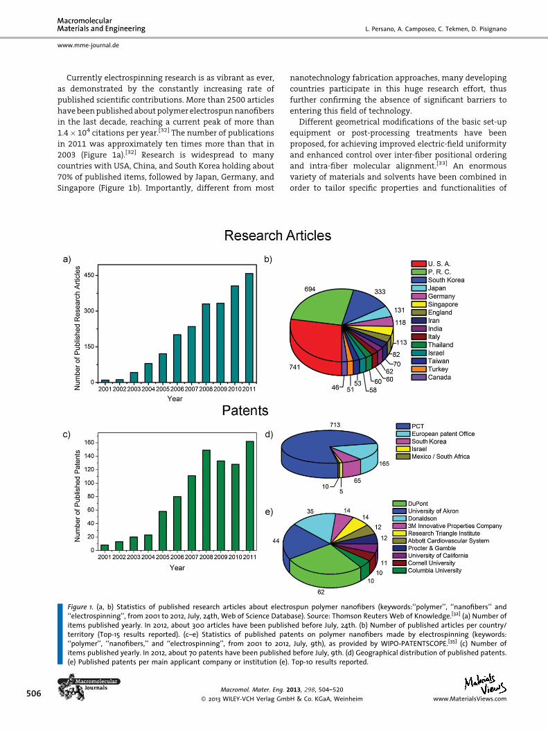
Currently electrospinning research is as vibrant as ever,
as demonstrated by the constantly increasing rate of
published scientific contributions. More than 2500 articles
have been published about polymer electrospun nanofibers
in the last decade, reaching a current peak of more than
1.4� 104 citations per year.[32] The number of publications
in 2011 was approximately ten times more than that in
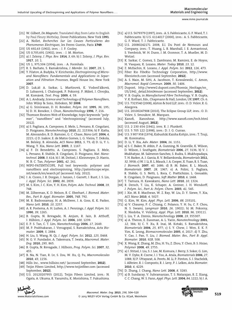
2003 (Figure 1a).[32] Research is widespread to many
countries with USA, China, and South Korea holding about
70% of published items, followed by Japan, Germany, and
Singapore (Figure 1b). Importantly, different from most
Figure 1. (a, b) Statistics of published research articles about electr‘‘electrospinning’’, from 2001 to 2012, July, 24th, Web of Science Databitems published yearly. In 2012, about 300 articles have been publishterritory (Top-15 results reported). (c–e) Statistics of published pat‘‘polymer’’, ‘‘nanofibers,’’ and ‘‘electrospinning’’, from 2001 to 2012items published yearly. In 2012, about 70 patents have been published(e) Published patents per main applicant company or institution (e)
Macromol. Mater. Eng. 2
� 2013 WILEY-VCH Verlag Gmb
nanotechnology fabrication approaches, many developing
countries participate in this huge research effort, thus
further confirming the absence of significant barriers to
entering this field of technology.
Different geometrical modifications of the basic set-up
equipment or post-processing treatments have been
proposed, for achieving improved electric-field uniformity
and enhanced control over inter-fiber positional ordering
and intra-fiber molecular alignment.[33] An enormous
variety of materials and solvents have been combined in
order to tailor specific properties and functionalities of
ospun polymer nanofibers (keywords:‘‘polymer’’, ‘‘nanofibers’’ andase). Source: Thomson Reuters Web of Knowledge.[32] (a) Number ofed before July, 24th. (b) Number of published articles per country/ents on polymer nanofibers made by electrospinning (keywords:, July, 9th), as provided by WIPO-PATENTSCOPE.[35] (c) Number of
before July, 9th. (d) Geographical distribution of published patents.. Top-10 results reported.
013, 298, 504–520
H & Co. KGaA, Weinheim www.MaterialsViews.com
Industrial Upscaling of Electrospinning and Applications of Polymer Nanofibers: . . .
www.mme-journal.de
electrospun products.[10,34] However, not all these achieve-
ments are easily transferable to industrial production.
On one hand, the number of issued patents has hugely
increased, as shown in Figure 1c (more than 160 patents have
been issued in 2011). Of 960 patents published in the last
decade,[35] 75% are international applications (Patent Coop-
eration Treaty, PCT), whereas the remaining are mainly
European (17%) and South Korean (7%) (Figure 1d). The top
patent owners include both companies such as DuPont (6%)
and Donaldson (4%), and universities (Figure 1e), with a major
focus of the overall patent portfolio on the development of
filtration media, methods, and apparatus.
On the other hand, the process scale-up is still largely
an issue even for electrospinning technologies, with a lot
of space for further improvements. For many classes of
materials, the achievable length of electrospun nanofibers
still ranges from hundreds of micrometers to millimeters,
which is useless for most technical applications. In these
cases, the method often exhibits poor performances in
terms of reproducibility and accuracy in the production
stage. These aspects are easily understandable given the
general reliability issues inherent to most of nanofabrica-
tion approaches dealing with soft materials and organic
solutions, and which are affected, in the case of electro-
spinning, by the complex physical behavior of electrified
jets and by the plethora of solution-, equipment-, and
ambient-dependent process parameters. Many polymer
systems are difficult to optimize with electrospinning, due
to their poor viscoelastic behavior, lack of sufficient
molecular entanglements, limited solubility, and, more
generally, because only a few processing parameters can be
chosen directly. In addition, some of the involved para-
meters are either highly interdependent or derive from the
properties of the used polymer solution. Industrially
produced electrospun nanofibers reach a dimensional
spread of the order of ten percentage points or worse
among nominally identical samples. Therefore, a main
challenge related with the mass production of nanofiber
fabrics is the implementation of methods allowing increase
of the process and product reproducibility and to extend the
classes of utilizable materials.
This paper provides an overview on electrospinning
technologies with focus on those approaches that show
large-scale capability. In addition it aims to present a
picture of the industrial background related to fabrication
equipment and nanofiber-based products. Many compa-
nies supplying either laboratory and large-scale electro-
spinning equipment, or nanofibrous products (mainly for
filtration) already exist and possess well-defined market
segments. New interesting perspectives can emerge for
nanofibers in the fields of renewable energy sources, such as
in photovoltaic devices, and in energy storage and manage-
ment, such as in battery separators, and many small and
multi-national companies are testing nanofibrous products
www.MaterialsViews.com
Macromol. Mater. Eng. 2
� 2013 WILEY-VCH Verlag Gmb
for biomedical applications. Overall, a tighter interaction
between the academic and the industrial communities and
a critical assessment of the weakness and strength points of
electrospinning technologies for industrial processes can
certainly be useful to stimulate future developments.
2. Spinning Technologies
Spinning technologies for fibers manufacturing are based
on a spinneret extrusion process which allows the
continuous production of single or multi-filament materi-
als. The resulting product exhibits different properties
depending on the specific process and parameters adopted.
In particular, with regard to the state of the material to spin,
such methods can be classified as melt spinning, solution
spinning, and emulsion spinning. From a manufacturing
point of view, polymer melt processing offers unique
advantages in terms of high-throughput rate and process
safety, whereas solvent-based methods are advantageous
in terms of the large variety of materials that can be spun,
lower energy consumption, and frequently superior
mechanical, optical, and electrical properties of the result-
ing fibers. Emulsion spinning is a method of choice for
processing polymers exhibiting high melting point, e.g.,
for the production of flame-retardant fibers. With respect
to traditional spinning methods, electrospinning of melts,
solutions or emulsions has unique advantages, such as
the capability to encapsulate functional dopants, light-
emitting dyes, drug and biomolecules and to induce high
alignment of both polymer and nanocomposite fibers. The
diameter range and peculiar morphology of electrospun
fibers mimic those of the extracellular matrix thus making
them particularly suitable for bio-scaffolds, and are ideal for
filtration and catalysis applications. Finally, electrospin-
ning is an especially flexible process, that can be carried
out through needleless systems, thus overcoming limits
imposed by the spinneret. In the following paragraphs
we briefly overview traditional and contemporary fiber-
forming spinning methods. Poly(lactide) (PLA) is among
the most widely used and studied prototypical polymer,
allowing comparison of spinning techniques and obtained
fiber properties (Table 1).[36–45]
2.1. Melt Spinning
In conventional melt spinning a polymeric system in the
melt state is extruded through a spinneret. The diameter
of fibers is reduced by mechanically drawing the contin-
uous flow at the wind-up and fibers solidification is
achieved by rapid cooling.[46] The structural properties of
the extruded filaments are mainly dependent on take-up
speed, drawing temperature and draw ratio (which is
a measure of the amount of stretching undergone by
013, 298, 504–520
H & Co. KGaA, Weinheim507
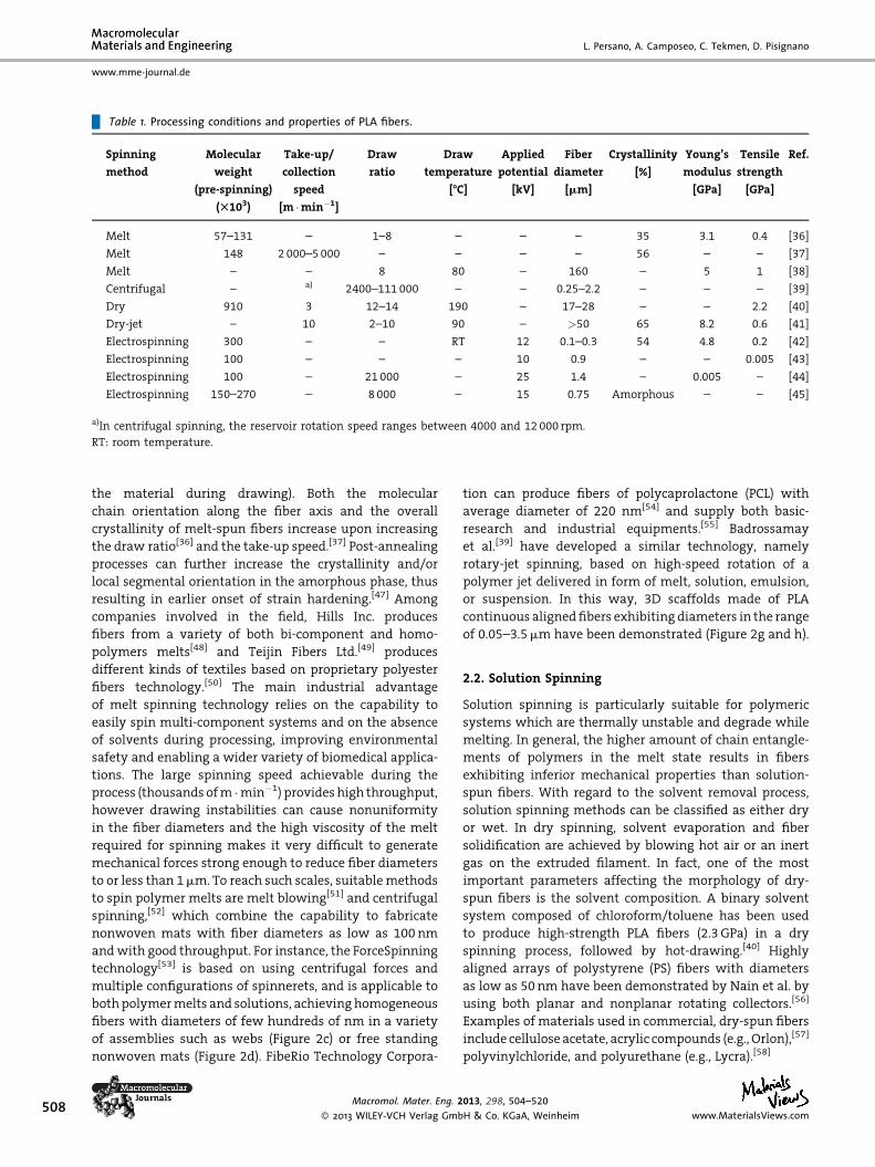
Table 1. Processing conditions and properties of PLA fibers.
Spinning
method
Molecular
weight
(pre-spinning)
(T103)
Take-up/
collection
speed
[m �min�1]
Draw
ratio
Draw
temperature
[-C]
Applied
potential
[kV]
Fiber
diameter
[mm]
Crystallinity
[%]
Young’s
modulus
[GPa]
Tensile
strength
[GPa]
Ref.
Melt 57–131 – 1–8 – – – 35 3.1 0.4 [36]
Melt 148 2 000–5 000 – – – – 56 – – [37]
Melt – – 8 80 – 160 – 5 1 [38]
Centrifugal – a) 2400–111 000 – – 0.25–2.2 – – – [39]
Dry 910 3 12–14 190 – 17–28 – – 2.2 [40]
Dry-jet – 10 2–10 90 – >50 65 8.2 0.6 [41]
Electrospinning 300 – – RT 12 0.1–0.3 54 4.8 0.2 [42]
Electrospinning 100 – – – 10 0.9 – – 0.005 [43]
Electrospinning 100 – 21 000 – 25 1.4 – 0.005 – [44]
Electrospinning 150–270 – 8 000 – 15 0.75 Amorphous – – [45]
a)In centrifugal spinning, the reservoir rotation speed ranges between 4000 and 12 000 rpm.
RT: room temperature.
508
www.mme-journal.de
L. Persano, A. Camposeo, C. Tekmen, D. Pisignano
the material during drawing). Both the molecular
chain orientation along the fiber axis and the overall
crystallinity of melt-spun fibers increase upon increasing
the draw ratio[36] and the take-up speed.[37] Post-annealing
processes can further increase the crystallinity and/or
local segmental orientation in the amorphous phase, thus
resulting in earlier onset of strain hardening.[47] Among
companies involved in the field, Hills Inc. produces
fibers from a variety of both bi-component and homo-
polymers melts[48] and Teijin Fibers Ltd.[49] produces
different kinds of textiles based on proprietary polyester
fibers technology.[50] The main industrial advantage
of melt spinning technology relies on the capability to
easily spin multi-component systems and on the absence
of solvents during processing, improving environmental
safety and enabling a wider variety of biomedical applica-
tions. The large spinning speed achievable during the
process (thousands of m �min�1) provides high throughput,
however drawing instabilities can cause nonuniformity
in the fiber diameters and the high viscosity of the melt
required for spinning makes it very difficult to generate
mechanical forces strong enough to reduce fiber diameters
to or less than 1 mm. To reach such scales, suitable methods
to spin polymer melts are melt blowing[51] and centrifugal
spinning,[52] which combine the capability to fabricate
nonwoven mats with fiber diameters as low as 100 nm
and with good throughput. For instance, the ForceSpinning
technology[53] is based on using centrifugal forces and
multiple configurations of spinnerets, and is applicable to
both polymer melts and solutions, achieving homogeneous
fibers with diameters of few hundreds of nm in a variety
of assemblies such as webs (Figure 2c) or free standing
nonwoven mats (Figure 2d). FibeRio Technology Corpora-
Macromol. Mater. Eng. 2
� 2013 WILEY-VCH Verlag Gmb
tion can produce fibers of polycaprolactone (PCL) with
average diameter of 220 nm[54] and supply both basic-
research and industrial equipments.[55] Badrossamay
et al.[39] have developed a similar technology, namely
rotary-jet spinning, based on high-speed rotation of a
polymer jet delivered in form of melt, solution, emulsion,
or suspension. In this way, 3D scaffolds made of PLA
continuous aligned fibers exhibiting diameters in the range
of 0.05–3.5 mm have been demonstrated (Figure 2g and h).
2.2. Solution Spinning
Solution spinning is particularly suitable for polymeric
systems which are thermally unstable and degrade while
melting. In general, the higher amount of chain entangle-
ments of polymers in the melt state results in fibers
exhibiting inferior mechanical properties than solution-
spun fibers. With regard to the solvent removal process,
solution spinning methods can be classified as either dry
or wet. In dry spinning, solvent evaporation and fiber
solidification are achieved by blowing hot air or an inert
gas on the extruded filament. In fact, one of the most
important parameters affecting the morphology of dry-
spun fibers is the solvent composition. A binary solvent
system composed of chloroform/toluene has been used
to produce high-strength PLA fibers (2.3 GPa) in a dry
spinning process, followed by hot-drawing.[40] Highly
aligned arrays of polystyrene (PS) fibers with diameters
as low as 50 nm have been demonstrated by Nain et al. by
using both planar and nonplanar rotating collectors.[56]
Examples of materials used in commercial, dry-spun fibers
include cellulose acetate, acrylic compounds (e.g., Orlon),[57]
polyvinylchloride, and polyurethane (e.g., Lycra).[58]
013, 298, 504–520
H & Co. KGaA, Weinheim www.MaterialsViews.com

Figure 2. (a) SEM micrograph of PEO fibers made by solution Force-spinning; (b) PS mats, (c) nanofibers web, and (d) free-standing nonwovenmats realized by the Force-spinning technology. Reproduced with permission.[53] Copyright 2010, Elsevier (e)-(f) Schematic illustrations ofthe rotary-jet spinning; (g)-(h) Images of a 3D scaffold made of PLA continuously aligned fibers; (j) SEM micrograph of rotary-jet spun fibersmade of PLA and produced under conditions of expedited solvent evaporation and high humidity; (k) PEO; (l)-(m) poly(acrylic acid);(n) gelatin fibers; (o) Laser scanning confocal image of PS beads encapsulated within PEO fibers; (p) SEM micrograph of gelatin/PLA fibersmade by emulsion Rotary-jet Spinning. Reproduced with permission.[39] Copyright 2010, American Chemical Society.
www.MaterialsViews.com
Macromol. Mater. Eng. 2013, 298, 504–520
� 2013 WILEY-VCH Verlag GmbH & Co. KGaA, Weinheim509
Industrial Upscaling of Electrospinning and Applications of Polymer Nanofibers: . . .
www.mme-journal.de
510
www.mme-journal.de
L. Persano, A. Camposeo, C. Tekmen, D. Pisignano
In wet spinning, the polymer solution is extruded in a
viscous coagulation bath consisting of a liquid which is
miscible with the spinning solvent, but is a nonsolvent for
the polymer. Exchange between solvent and nonsolvent
causes phase separation which leads to solvent removal
from the spun filaments, and fibers solidify while
precipitation occurs. The solidification involves mass
transfer through the polymeric solution–nonsolvent inter-
face, which can lead to defects, such as voids and cross
shape irregularities.[46] The formation of such defects can
be limited by introducing an air-gap (3–5 mm) between
the end of the spinneret and the coagulation bath. In this
approach, named dry-jet or air-gap wet spinning, the
filaments are firstly extruded through the air-gap, which
allows stress relaxation of polymer chains, and then
quenched in the bath.[46] An extensive study on PLA
fibers, carried out by varying dry-jet spinning parameters,
demonstrates high tensile strength (0.6 GPa) and
high Young’s modulus (8.2 GPa).[41] In 2008, Velev and
Alargova[59] have patented a method based on the
application of a shear force in wet spinning. In this way,
during precipitation polymer filaments are tightly
stretched, and nanofibers with high aspect ratios (100
or higher) and average diameter ranging from 100 nm to
5 mm can be obtained.[60] On a pilot commercial machine,
Xanofi demonstrate continuous production of fibers at
rates exceeding 60 g �min�1.[61]
2.3. Emulsion Spinning
This technique is usually employed to spin insoluble and
non-melting compounds. Such materials are typically
finely ground and mixed with solutions made of different
polymers. Catalysts and emulsifier agents are also added.
The emulsion is then extruded into a coagulation bath,
similarly to wet spinning, or in air, similarly to dry spinning.
The method allows the production of fibers made of
fluorocarbons exhibiting high melting point,[62] inorganic
materials such as ceramics[63] and blends with flame-
retardant properties.[64]
3. Electrospinning Production Technologies
The basic laboratory equipment for electrospinning con-
sists of three major components, i.e., (i) a high-voltage
power supply, (ii) a spinneret (a metallic needle), and (iii) a
metallic collector. A high-voltage direct current (DC) power
is supplied to the spinneret, whose fluidics are usually
connected to a syringe pump injecting the polymer solution
to be spun, while the collector is usually ground- or
negatively biased. When a high voltage is applied, a
pendent drop of the polymer solution experiences forces
due to surface tension and to the external field, together
Macromol. Mater. Eng. 2
� 2013 WILEY-VCH Verlag Gmb
with stresses related to electrostatic repulsion between
surface charges that deform the liquid–air interface into a
conical shape (Taylor cone).[65] When the electrostatic force
acting on the surface of the liquid overcomes the surface
tension, a charged liquid jet is pulled from the Taylor cone
and ejected toward the target electrode. Polymer nanofibers
are normally deposited on the collector in form of
nonwovens. Specific modifications to the basic experi-
mental set-up have been introduced for improving the
quality of nanofibers and for tuning their properties
according to requirements of different applications. In
particular, in view of large-scale production and of
applications that clearly show significant commercial
potential, in the next paragraphs we analyze some
technological improvements targeting the fields
of environment and energy, photonics and electronics,
filtration, and biomedicine (in turn including tissue
engineering, wound healing, and drug delivery).
3.1. Uniaxial Alignment of Nanofibers
The uniaxial alignment of nanofibers within ordered array
is demonstrated to be important for different applications,
thus becoming an important prerequisite to be taken into
account in scaling-up the electrospinning production
capability. In the field of tissue regeneration addressed to
muscles, bone and cartilage meniscus, and neural cells,
several groups show that cell cultures on uniaxially aligned
nanofibrous scaffolds preferentially elongate along the
fiber longitudinal axis.[66] In the field of photonics, mats
of uniaxially aligned nanofibers can be used as optical
polarizers[33d] and for decoupling sample emission and
excitation signals in lab-on-chip devices,[12d] whereas
composite samples containing aligned sulfonated poly-
imide nanofibers can be employed in proton-exchange
membrane fuel cells for converting chemical energy to
electrical energy with high efficiency and low emission of
pollutants.[67] Due to such high added value of uniaxially
aligned nanofiber yarns, many modifications of the
electrospinning collector geometry have been made,
specifically aimed to improve and control nanofiber
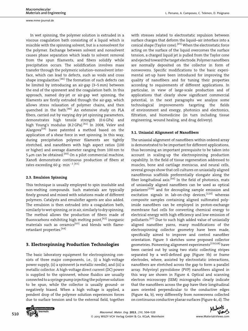
orientation. Figure 3 sketches some proposed collector
geometries. Pioneering alignment experiments[33d,68] have
been carried out by using two static collecting stripes
separated by a well-defined gap (Figure 3b) or frame
electrodes, where, assisted by electrostatic interactions,
nanofibers are stretched across the gap to form a parallel
array. Polyvinyl pyrrolidone (PVP) nanofibers aligned in
this way are shown in Figure 4. Optical and scanning
electron microscopy (SEM) micrographs clearly indicate
that the nanofibers across the gap have their longitudinal
axes oriented perpendicular to the conductive edges
(Figure 4a, b), very differently from nonwovens collected
on continuous conductive planar surfaces (Figure 4c, d). The
013, 298, 504–520
H & Co. KGaA, Weinheim www.MaterialsViews.com
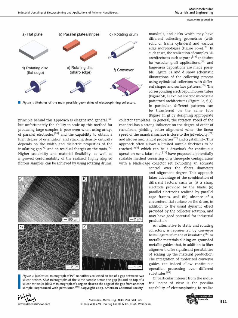
Figure 3. Sketches of the main possible geometries of electrospinning collectors.
Industrial Upscaling of Electrospinning and Applications of Polymer Nanofibers: . . .
www.mme-journal.de
principle behind this approach is elegant and general,[69]
but unfortunately the ability to scale-up this method for
producing large samples is poor even when using arrays
of parallel electrodes,[70] and the capability to obtain a
high degree of orientation and stacking density critically
depends on the width and dielectric properties of the
insulating gap[71] and on residual charges on the mats.[72]
Higher scalability and material flexibility, as well as
improved conformability of the realized, highly aligned
fibrous samples, can be achieved by using rotating drums,
Figure 4. (a) Optical micrograph of PVP nanofibers collected on top of a gap between twosilicon stripes. SEM micrographs of the same sample across the gap (b) and on top of asilicon stripe (c). (d) SEM micrograph of a region close to the edge of the gap from anothersample. Reproduced with permission.[33d] Copyright 2003, American Chemical Society.
www.MaterialsViews.com
Macromol. Mater. Eng. 2013, 298, 504–520
� 2013 WILEY-VCH Verlag GmbH & Co. KGaA, Weinhei
mandrels, and disks which may have
different collecting geometries (with
solid or frame cylinders) and various
edge morphologies (Figure 3c–e).[73] In
such cases, the realization of complex 3D
architectures such as yarns[74] and tubes
for vascular graft applications,[75] and
large-area depositions are made possi-
ble. Figure 5a and d show schematic
illustrations of the collecting process
using cylindrical collectors with differ-
ent shapes and surface patterns.[76] The
corresponding electrospun fibrous tubes
(Figure 5b, e) exhibit specific microscale
patterned architectures (Figure 5c, f, g).
In particular, different patterns can
be transferred on the same tube
(Figure 5f, g) by designing appropriate
collector templates. In general, the rotation speed of the
mandrel has a strong influence on the degree of order of
nanofibers, yielding better alignment when the linear
speed of the mandrel surface is close to the jet velocity,[77]
and also on mechanical properties[78] and crystallinity. This
approach often allows a limited sample thickness to be
reached,[33b] which can be a drawback for continuous
operation runs. Jafari et al.[79] have proposed a potentially
scalable method consisting of a three-pole configuration
with a blade-cage collector set exhibiting an accurate
control over the fibers diameters
and alignment degree. This approach
takes advantage of the combination of
different factors, such as (i) a sharp
electrode provided by the blade, (ii)
parallel electrodes realized by parallel
cage frames, and (iii) absence of a
circumferential surface on the drum, in
addition to the usual dynamic effect
provided by the collector rotation, and
may have good potential for industrial
production.
An alternative to static and rotating
collectors, is represented by conveyor
belts (Figure 3f) made of insulating[80] or
metallic materials sliding on grounded
metallic guides that, in addition to fiber
alignment, offer significant possibilities
of scaling up the material production.
The integration of motorized conveyor
guides can indeed allow continuous
operation processing over different
substrates.[81]
Of particular interest from the indus-
trial point of view is the peculiar
capability of electrospinning to realize
m511

Figure 5. (a) Scheme of specialized nanofibers collection processes during electrospin-ning (es), by using a cylindrical collector with equally spaced circular protrusions (pc,patterned collector). (b) An electrospun fibrous tube with patterned architectures (scalebar¼ 5 mm). (c) Magnified micrograph of a portion of the same tube in (b). Scalebar¼ 200 mm. (d) Scheme of a patterned collector (pc) and a fibrous tube (ft) exhibitingtwo different surface patterns. (e) An electrospun fibrous tube with two differentsurface patterns (scale bar¼ 5 mm). (f) and (g) are magnified images of two differentportions of the same tube in (e). Scale bars¼ 200 mm. Reproduced with permission.[76]
Copyright 2008, American Chemical Society.
512
www.mme-journal.de
L. Persano, A. Camposeo, C. Tekmen, D. Pisignano
complex bi- and tri-dimensional architectures in a single
run, and engineering the collector geometry is strategic in
this respect. Yarns, two-dimensional meshes and tubes can
exhibit interesting properties for prosthetic implant
devices[82] and for blood vessel reconstruction,[83] thus
being attractive for pharmaceutical companies. Zhang
and Chang have reported on a method to fabricate
3D fibrous tubes with multiple micropatterns composed
of electrospun nanofibers.[76] Micro- and macroscale
tubes (diameter 500 mm–5 mm) with different shapes,
structures, patterns, and T-shape interconnections have
been prepared.
Finally, a very high degree of order can be achieved by
coupling the application of additional centrifugal forces to
Macromol. Mater. Eng. 2013, 298, 504–520
� 2013 WILEY-VCH Verlag GmbH & Co. KGaA, Weinhe
the jet with electrostatic forces. Electro-
spinning experiments have been per-
formed both under high operating
voltage (� 5 kV) and rotational speed
(1 800 rpm) for the fabrication of PLA
fibers exhibiting improved mechanical
properties,[84] and under low operating
voltage (2.8 kV) and speed (390 rpm) for
the fabrication of PS, polymethyl metha-
crylate (PMMA) and PVP fibers exhibiting
(95.5� 2.9)% of fibers with mutual align-
ment within 58.[85]
3.2. Scaling Volumes Through
Injection Systems
Another important issue concerning
process up-scaling for commercial
purposes is related to the production
capacity of the set-up. High volumes are
especially desirable for biomedical
applications such as tissue engineering,
design of wound-healing materials,
drug-delivery for air/liquid filtration,
and for textile applications.
In the framework of tissue engineer-
ing, electrospinning is particularly
suitable for the fabrication of 3D scaf-
folds since the final products fit most of
requirements in terms of material por-
osity (defined as the number of 3D,
unfilled voids among nanofibers[11c]),
large surface-area-to-volume ratio, and
tunable mechanical properties.[86]
For wound healing, electrospun, inter-
connected porous structures are advan-
tageous for oozing fluids, controlling
drainage and facilitating oxygen per-
meation, and in addition the flexibility of
the electrospinning process allows the
addition of drugs in the nanofibers, for medical treatment
and antibacterial purposes. Figure 6a shows a prototype of
scaffold, made of PCL/gelatin nanofibers directly electro-
spun onto polyurethane for wound dressing.[87] SEM
micrographs of this construct (Figure 6b) show randomly
interconnected structures with fiber diameters in the range
300–600 nm.
The potentiality of nanofibers in drug delivery has been
investigated by several chemical drugs,[88] proteins,[89] and
macromolecules such as DNA[90] with clear advantages
over bulk materials due to the large specific surface and
short diffusion path lengths. In particular, taking these
scaffolds close to the market has to pass through in vivo
studies before clinical validations. The volume of related
im www.MaterialsViews.com
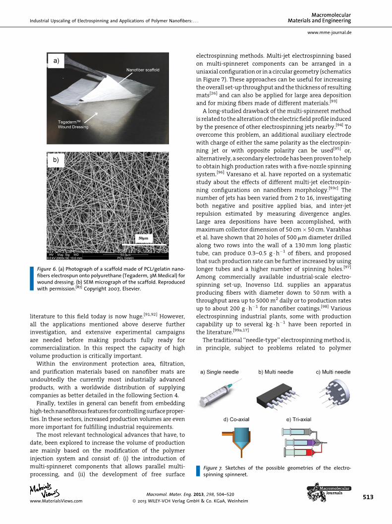
Figure 6. (a) Photograph of a scaffold made of PCL/gelatin nano-fibers electrospun onto polyurethane (Tegaderm, 3M Medical) forwound dressing. (b) SEM micrograph of the scaffold. Reproducedwith permission.[87] Copyright 2007, Elsevier.
Figure 7. Sketches of the possible geometries of the electro-spinning spinneret.
Industrial Upscaling of Electrospinning and Applications of Polymer Nanofibers: . . .
www.mme-journal.de
literature to this field today is now huge.[91,92] However,
all the applications mentioned above deserve further
investigation, and extensive experimental campaigns
are needed before making products fully ready for
commercialization. In this respect the capacity of high
volume production is critically important.
Within the environment protection area, filtration,
and purification materials based on nanofiber mats are
undoubtedly the currently most industrially advanced
products, with a worldwide distribution of supplying
companies as better detailed in the following Section 4.
Finally, textiles in general can benefit from embedding
high-technanofibrous features for controlling surfaceproper-
ties. In these sectors, increased production volumes are even
more important for fulfilling industrial requirements.
The most relevant technological advances that have, to
date, been explored to increase the volume of production
are mainly based on the modification of the polymer
injection system and consist of: (i) the introduction of
multi-spinneret components that allows parallel multi-
processing, and (ii) the development of free surface
www.MaterialsViews.com
Macromol. Mater. Eng. 2
� 2013 WILEY-VCH Verlag Gmb
electrospinning methods. Multi-jet electrospinning based
on multi-spinneret components can be arranged in a
uniaxial configuration or in a circular geometry (schematics
in Figure 7). These approaches can be useful for increasing
the overall set-up throughput and the thickness of resulting
mats[26] and can also be applied for large area deposition
and for mixing fibers made of different materials.[93]
A long-studied drawback of the multi-spinneret method
is related to the alteration of the electric field profile induced
by the presence of other electrospinning jets nearby.[94] To
overcome this problem, an additional auxiliary electrode
with charge of either the same polarity as the electrospin-
ning jet or with opposite polarity can be used[95] or,
alternatively, a secondary electrode has been proven to help
to obtain high production rates with a five-nozzle spinning
system.[96] Varesano et al. have reported on a systematic
study about the effects of different multi-jet electrospin-
ning configurations on nanofibers morphology.[93c] The
number of jets has been varied from 2 to 16, investigating
both negative and positive applied bias, and inter-jet
repulsion estimated by measuring divergence angles.
Large area depositions have been accomplished, with
maximum collector dimension of 50 cm� 50 cm. Varabhas
et al. have shown that 20 holes of 500 mm diameter drilled
along two rows into the wall of a 130 mm long plastic
tube, can produce 0.3–0.5 g �h�1 of fibers, and proposed
that such production rate can be further increased by using
longer tubes and a higher number of spinning holes.[97]
Among commercially available industrial-scale electro-
spinning set-up, Inovenso Ltd. supplies an apparatus
producing fibers with diameter down to 50 nm with a
throughput area up to 5000 m2 daily or to production rates
up to about 200 g �h�1 for nanofiber coatings.[98] Various
electrospinning industrial plants, some with production
capability up to several kg �h�1 have been reported in
the literature.[99a,17]
The traditional ‘‘needle-type’’ electrospinning method is,
in principle, subject to problems related to polymer
013, 298, 504–520
H & Co. KGaA, Weinheim513
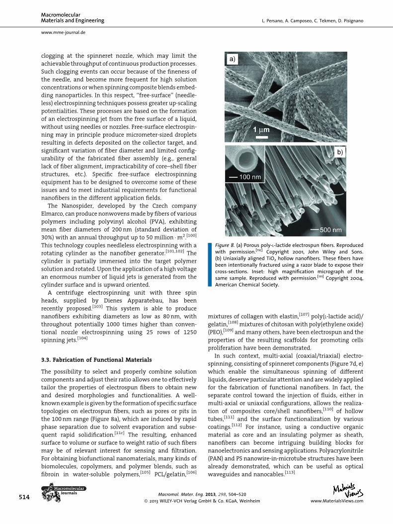
Figure 8. (a) Porous poly-L-lactide electrospun fibers. Reproducedwith permission.[11c] Copyright 2001, John Wiley and Sons.(b) Uniaxially aligned TiO2 hollow nanofibers. These fibers havebeen intentionally fractured using a razor blade to expose theircross-sections. Inset: high magnification micrograph of thesame sample. Reproduced with permission.[111] Copyright 2004,American Chemical Society.
514
www.mme-journal.de
L. Persano, A. Camposeo, C. Tekmen, D. Pisignano
clogging at the spinneret nozzle, which may limit the
achievable throughput of continuous production processes.
Such clogging events can occur because of the fineness of
the needle, and become more frequent for high solution
concentrations or when spinning composite blends embed-
ding nanoparticles. In this respect, ‘‘free-surface’’ (needle-
less) electrospinning techniques possess greater up-scaling
potentialities. These processes are based on the formation
of an electrospinning jet from the free surface of a liquid,
without using needles or nozzles. Free-surface electrospin-
ning may in principle produce micrometer-sized droplets
resulting in defects deposited on the collector target, and
significant variation of fiber diameter and limited config-
urability of the fabricated fiber assembly (e.g., general
lack of fiber alignment, impracticability of core–shell fiber
structures, etc.). Specific free-surface electrospinning
equipment has to be designed to overcome some of these
issues and to meet industrial requirements for functional
nanofibers in the different application fields.
The Nanospider, developed by the Czech company
Elmarco, can produce nonwovens made by fibers of various
polymers including polyvinyl alcohol (PVA), exhibiting
mean fiber diameters of 200 nm (standard deviation of
30%) with an annual throughput up to 50 million �m2.[100]
This technology couples needleless electrospinning with a
rotating cylinder as the nanofiber generator.[101,102] The
cylinder is partially immersed into the target polymer
solution and rotated. Upon the application of a high voltage
an enormous number of liquid jets is generated from the
cylinder surface and is upward oriented.
A centrifuge electrospinning unit with three spin
heads, supplied by Dienes Apparatebau, has been
recently proposed.[103] This system is able to produce
nanofibers exhibiting diameters as low as 80 nm, with
throughout potentially 1000 times higher than conven-
tional nozzle electrospinning using 25 rows of 1250
spinning jets.[104]
3.3. Fabrication of Functional Materials
The possibility to select and properly combine solution
components and adjust their ratio allows one to effectively
tailor the properties of electrospun fibers to obtain new
and desired morphologies and functionalities. A well-
known example is given by the formation of specific surface
topologies on electrospun fibers, such as pores or pits in
the 100 nm range (Figure 8a), which are induced by rapid
phase separation due to solvent evaporation and subse-
quent rapid solidification.[11c] The resulting, enhanced
surface to volume or surface to weight ratio of such fibers
may be of relevant interest for sensing and filtration.
For obtaining biofunctional nanomaterials, many kinds of
biomolecules, copolymers, and polymer blends, such as
fibroin in water-soluble polymers,[105] PCL/gelatin,[106]
Macromol. Mater. Eng. 2
� 2013 WILEY-VCH Verlag Gmb
mixtures of collagen with elastin,[107] poly(L-lactide acid)/
gelatin,[108] mixtures of chitosan with poly(ethylene oxide)
(PEO),[109] and many others, have been electrospun and the
properties of the resulting scaffolds for promoting cells
proliferation have been demonstrated.
In such context, multi-axial (coaxial/triaxial) electro-
spinning, consisting of spinneret components (Figure 7d, e)
which enable the simultaneous spinning of different
liquids, deserve particular attention and are widely applied
for the fabrication of functional nanofibers. In fact, the
separate control toward the injection of fluids, either in
multi-axial or uniaxial configurations, allows the realiza-
tion of composites core/shell nanofibers,[110] of hollow
tubes,[111] and the surface functionalization by various
coatings.[112] For instance, using a conductive organic
material as core and an insulating polymer as sheath,
nanofibers can become intriguing building blocks for
nanoelectronics and sensing applications. Polyacrylonitrile
(PAN) and PS nanowire-in-microtube structures have been
already demonstrated, which can be useful as optical
waveguides and nanocables.[113]
013, 298, 504–520
H & Co. KGaA, Weinheim www.MaterialsViews.com
Industrial Upscaling of Electrospinning and Applications of Polymer Nanofibers: . . .
www.mme-journal.de
Coaxial electrospinning is also useful for the encapsula-
tion of nonspinnable materials such as nanoparticles or
conjugated polymers exhibiting a poor thermoplastic
behavior,[114] enzymes, protein, and cells.[115] It has been
exploited to encapsulate self-healing materials (dicyclo-
pentadiene and isophorone diisocyanate),[116] the complex
hydride ammonia which find application for hydrogen
storage,[117] and several drugs within polymers. In parti-
cular, core–shell fibers provide a release pattern different
from bi-component monolithic fibers.[118] Additionally,
coaxial electrospinning offers the possibility to combine
product multi-functionality with good production volumes
by exploiting multi-coaxial systems, analogously to the
multi-needle configurations described above.
Coaxial electrospinning was first reported by Sun et al. in
2003.[119] In these early experiments, homopolymer core–
shell nanofibers as well as double-polymer fibers were
fabricated by a specifically engineered tip of concentric
capillaries (scheme in Figure 7d). The core–shell fiber
morphology is initiated by a structured Taylor cone
formed at the exit of the coaxial tubes. A liquid jet emerges
simultaneously from the vertices of the outer and
inner meniscus, forming a co-flowing jet. A stable jet is
generally formed if at least one of the involved polymer is
electrospinnable. The method has been adapted to prepare
hollow tubular nanofibers by using an extractable liquid as
core material and a sol–gel precursor as shell to make a
stronger inorganic sheath.[111,120] Hollow fibers made by Li
and Xia with PVP blended with titanium isopropoxide and
successive calcination are shown in Figure 8b.[111]
Other coaxial systems are based on pumping two
independent polymer solutions into two concentric capil-
laries, with the inner capillary tube which also acts as an
electrode for the spinning dopes, being positively biased
with respect to the collector.[121] Reznik et al. have showed
that the jetting effect at the tip of the shell nozzle does not
necessarily cause entrainment of the core fluid and in
such a case, core–shell nanofibers are not formed.[122] They
have suggested that co-electrospinning is greatly facilitated
by extending the core nozzle outside the shell outlet by
about half the radius of the latter. Bazilevsky et al. have
demonstrated that electrospinning of core–shell polymer
nanofibers is even possible in an ordinary single-nozzle
set-up by using an emulsion of the two polymer solutions.
The continuous phase experiences very strong stretching
forces leading to the formation of a core–shell jet.[123] Multi-
fluidic coaxial electrospinning has been recently developed
by three coaxial capillaries and a chemically inert middle
fluid that works as spacer between the outer and inner
fluids.[124] Finally, combining co-electrospinning with a
high speed gas jet allows the fabrication of core–shell
PMMA/PAN nanofibers that, after carbonization, yield
carbon tubes with inner diameter 50–150 nm and outer
diameter 400–600 nm.[125]
www.MaterialsViews.com
Macromol. Mater. Eng. 2
� 2013 WILEY-VCH Verlag Gmb
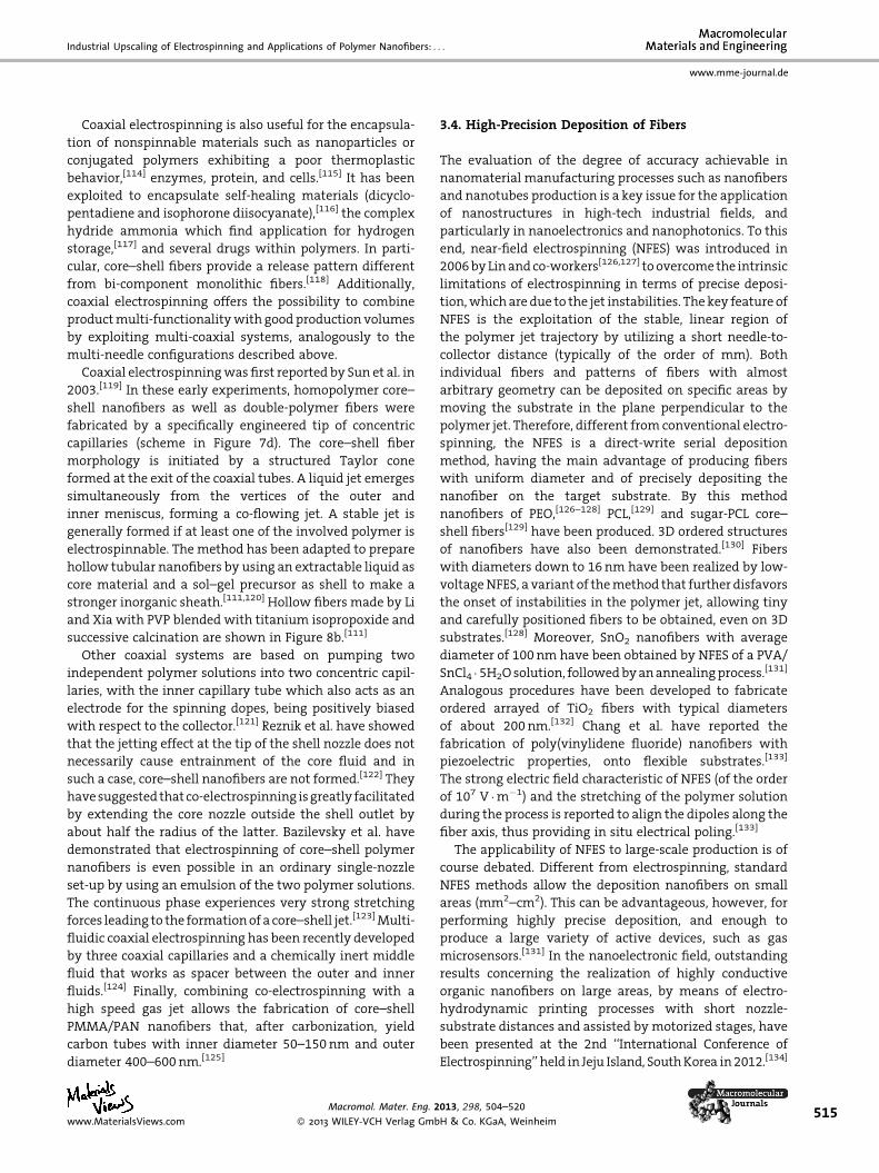
3.4. High-Precision Deposition of Fibers
The evaluation of the degree of accuracy achievable in
nanomaterial manufacturing processes such as nanofibers
and nanotubes production is a key issue for the application
of nanostructures in high-tech industrial fields, and
particularly in nanoelectronics and nanophotonics. To this
end, near-field electrospinning (NFES) was introduced in
2006 by Lin and co-workers[126,127] to overcome the intrinsic
limitations of electrospinning in terms of precise deposi-
tion, which are due to the jet instabilities. The key feature of
NFES is the exploitation of the stable, linear region of
the polymer jet trajectory by utilizing a short needle-to-
collector distance (typically of the order of mm). Both
individual fibers and patterns of fibers with almost
arbitrary geometry can be deposited on specific areas by
moving the substrate in the plane perpendicular to the
polymer jet. Therefore, different from conventional electro-
spinning, the NFES is a direct-write serial deposition
method, having the main advantage of producing fibers
with uniform diameter and of precisely depositing the
nanofiber on the target substrate. By this method
nanofibers of PEO,[126–128] PCL,[129] and sugar-PCL core–
shell fibers[129] have been produced. 3D ordered structures
of nanofibers have also been demonstrated.[130] Fibers
with diameters down to 16 nm have been realized by low-
voltage NFES, a variant of the method that further disfavors
the onset of instabilities in the polymer jet, allowing tiny
and carefully positioned fibers to be obtained, even on 3D
substrates.[128] Moreover, SnO2 nanofibers with average
diameter of 100 nm have been obtained by NFES of a PVA/
SnCl4 � 5H2O solution, followed by an annealing process.[131]
Analogous procedures have been developed to fabricate
ordered arrayed of TiO2 fibers with typical diameters
of about 200 nm.[132] Chang et al. have reported the
fabrication of poly(vinylidene fluoride) nanofibers with
piezoelectric properties, onto flexible substrates.[133]
The strong electric field characteristic of NFES (of the order
of 107 V �m�1) and the stretching of the polymer solution
during the process is reported to align the dipoles along the
fiber axis, thus providing in situ electrical poling.[133]
The applicability of NFES to large-scale production is of
course debated. Different from electrospinning, standard
NFES methods allow the deposition nanofibers on small
areas (mm2–cm2). This can be advantageous, however, for
performing highly precise deposition, and enough to
produce a large variety of active devices, such as gas
microsensors.[131] In the nanoelectronic field, outstanding
results concerning the realization of highly conductive
organic nanofibers on large areas, by means of electro-
hydrodynamic printing processes with short nozzle-
substrate distances and assisted by motorized stages, have
been presented at the 2nd ‘‘International Conference of
Electrospinning’’ held in Jeju Island, South Korea in 2012.[134]
013, 298, 504–520
H & Co. KGaA, Weinheim515
516
www.mme-journal.de
L. Persano, A. Camposeo, C. Tekmen, D. Pisignano
4. Electrospinning: From Laboratoriesto Industry
Though the benefits of electrospinning technologies have
been largely demonstrated for many application fields
where polymer nanofibers can be used, there is still a strong
need to implement the production in the most efficient
way, in order to address the pressing issues concerning: (i)
large volume processing, (ii) accuracy and reproducibility in
all the fabrication stages, and (iii) safety and environmental
attributes of electrospinning.
The scaling capability of the process and the technolo-
gical issues explored to date evidence that free-surface
methods exhibit high up-scaling potentialities in terms of
production volumes. Also centrifugal electrospinning may
in principle become widespread industrially, and the
capability of this approach to achieve nanofiber diameters
down to 100 nm has been demonstrated.[103] On the other
side, higher flexibility toward materials and processing and
consequently more various functionalities of the resulting
nanofibers can be achieved by co-axial and multi-axial
technologies, that also offer possibility for scale-up if multi-
needle approaches are adopted together with suitable
methods to reduce multi-jet related instabilities.
Many advanced applications and active polymer materi-
als are still limited due to the lack of reliable and affordable
electrospinning approaches which can guarantee the very
high needed accuracy and reproducibility of the fabrication
process, and the convergence between theoretical model-
ing and real-time control over the involved parameters
which would be useful in this respect to offer new
processing solutions extending the variety of usable
compounds. Finally, it is largely demonstrated that
ambient conditions strongly influence the properties of
electrified jets and of resulting electrospun materials, and
even small environmental perturbations can cause sig-
nificant variations of the fiber properties. To address this
issue, many providers of commercial set-ups have devel-
oped proprietary climate-controlled electrospinning sys-
tems guaranteeing temperature and humidity control
within certain ranges. For example, IME Technologies
supplies a laboratory-scale system consisting of an
electrospinning chamber and a control cabinet that houses
the air conditioning, water filtration and control system.
They guarantee� 0.5 8C accuracy in the control of tem-
perature (for the working range 20–45 8C) and� 1% in
the control of relative humidity (for the working range:
10–90%).[135]
Another important concern regards process environ-
mental issues about solvent-electrospun materials. This
aspect is very important not only for safety reasons
during processing, but also for final products since solvent
residues could be trapped inside the produced nanofibers.
Solvent-based electrospinning with high control over
Macromol. Mater. Eng. 2
� 2013 WILEY-VCH Verlag Gmb
fiber morphology and functionality could be safely used
in nontextile applications where production volumes
are moderate (e.g., nanoelectronics), whereas an accurate
control over solvent residuals become crucial for biomedical
and pharmaceutical applications. Novel formulations
of electrospinning materials processable by aqueous
solutions should therefore be developed, possibly also
including active and conjugated polymers, to reduce as
much as possible the consumption of volatile organic
solvents.
4.1. Electrospinning Apparatus at Laboratory and
Industrial Scale
From the commercial viewpoint, the rising interest in
electrospinning has already produced increased competi-
tion among laboratory-scale equipment suppliers. To gain
more market shares, companies offer different spinning
and collecting-electrode devices and accessories. A wide
selection of laboratory-scale electrospinning equipment is,
therefore, available in the market. A few key players on the
industrial-scale equipment market also exist, and these
companies can be distinguished on the basis of equipment
types and applications. A list of representative companies
supplying electrospinning equipments includes: Elmarco
(www.elmarco.com), NaBond (www.electro-spinning.com),
Holmarc Opto-Mechatronics (www.holmarc.com), E-Spin
Nanotech (www.espinnanotech.com), Linari Engineering
(www.linaribiomedical.com), Kato Tech (www.keskato.co.jp),
Mecc Co. (www.mecc.co.jp), Toptec (www.toptec.co.kr),
Electrospinz (www.electrospinz.co.nz), Electrospunra
(www.electrospunra.com), IME Technologies (www.
imetechnologies.nl), Yflow (www.yflow.com), and Ino-
venso (www.inovenso.com). Most of the laboratory-scale
equipment is based on needle-type electrospinning, with
production rates relatively low, but definitely adequate
to implement applied research. Concerning accessories
and components, many different spinning and collecting
electrode systems are available, particularly for laboratory-
scale apparatus, including controllers and high-speed
cameras. In industrial systems, nanofibers are mainly
collected on a rotating drum or on substrates by using
winding–unwinding systems.
For commercial systems targeting academic research,
achieving multi-functionality and flexibility is very impor-
tant for an equipment to be capable of carrying out different
research projects. Key requirements to be fulfilled include:
(i) price reduction, since most customers are from academia
and governmental institutions, (ii) multi-functional set-up,
which is often challenging, given the difficulty to offer
‘‘all-in-one’’ set-ups to meet different requirements from
the customer, and (iii) compactness, which is critically
important for equipment to be installed in laboratories
with limited space. A few representative laboratory-
013, 298, 504–520
H & Co. KGaA, Weinheim www.MaterialsViews.com
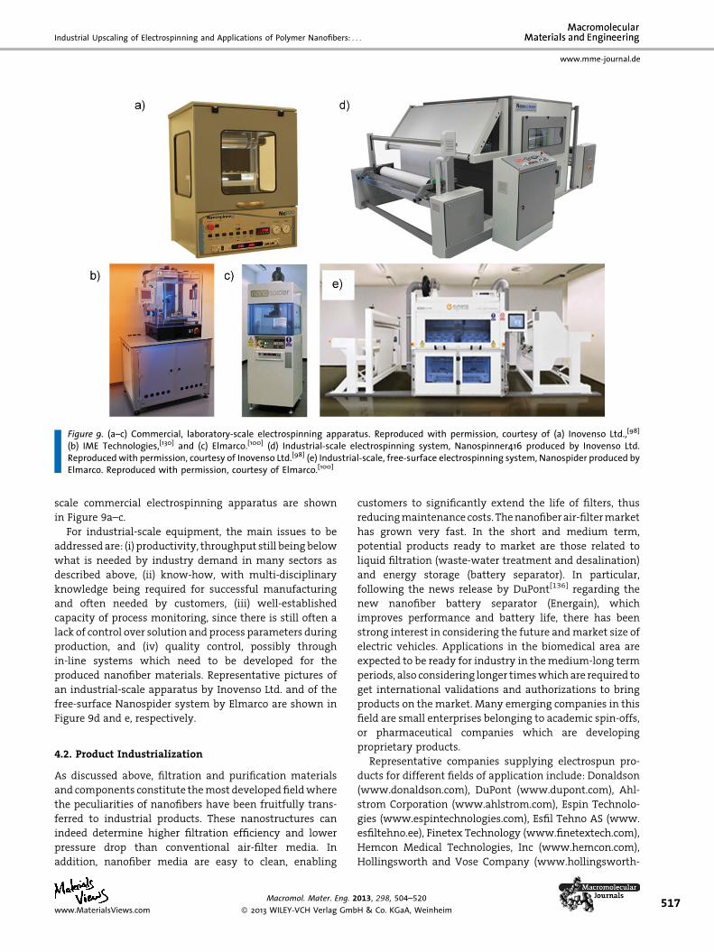
Figure 9. (a–c) Commercial, laboratory-scale electrospinning apparatus. Reproduced with permission, courtesy of (a) Inovenso Ltd.,[98]
(b) IME Technologies,[130] and (c) Elmarco.[100] (d) Industrial-scale electrospinning system, Nanospinner416 produced by Inovenso Ltd.Reproduced with permission, courtesy of Inovenso Ltd.[98] (e) Industrial-scale, free-surface electrospinning system, Nanospider produced byElmarco. Reproduced with permission, courtesy of Elmarco.[100]
Industrial Upscaling of Electrospinning and Applications of Polymer Nanofibers: . . .
www.mme-journal.de
scale commercial electrospinning apparatus are shown
in Figure 9a–c.
For industrial-scale equipment, the main issues to be
addressed are: (i) productivity, throughput still being below
what is needed by industry demand in many sectors as
described above, (ii) know-how, with multi-disciplinary
knowledge being required for successful manufacturing
and often needed by customers, (iii) well-established
capacity of process monitoring, since there is still often a
lack of control over solution and process parameters during
production, and (iv) quality control, possibly through
in-line systems which need to be developed for the
produced nanofiber materials. Representative pictures of
an industrial-scale apparatus by Inovenso Ltd. and of the
free-surface Nanospider system by Elmarco are shown in
Figure 9d and e, respectively.
4.2. Product Industrialization
As discussed above, filtration and purification materials
and components constitute the most developed field where
the peculiarities of nanofibers have been fruitfully trans-
ferred to industrial products. These nanostructures can
indeed determine higher filtration efficiency and lower
pressure drop than conventional air-filter media. In
addition, nanofiber media are easy to clean, enabling
www.MaterialsViews.com
Macromol. Mater. Eng. 2
� 2013 WILEY-VCH Verlag Gmb
customers to significantly extend the life of filters, thus
reducing maintenance costs. The nanofiber air-filter market
has grown very fast. In the short and medium term,
potential products ready to market are those related to
liquid filtration (waste-water treatment and desalination)
and energy storage (battery separator). In particular,
following the news release by DuPont[136] regarding the
new nanofiber battery separator (Energain), which
improves performance and battery life, there has been
strong interest in considering the future and market size of
electric vehicles. Applications in the biomedical area are
expected to be ready for industry in the medium-long term
periods, also considering longer times which are required to
get international validations and authorizations to bring
products on the market. Many emerging companies in this
field are small enterprises belonging to academic spin-offs,
or pharmaceutical companies which are developing
proprietary products.
Representative companies supplying electrospun pro-
ducts for different fields of application include: Donaldson
(www.donaldson.com), DuPont (www.dupont.com), Ahl-
strom Corporation (www.ahlstrom.com), Espin Technolo-
gies (www.espintechnologies.com), Esfil Tehno AS (www.
esfiltehno.ee), Finetex Technology (www.finetextech.com),
Hemcon Medical Technologies, Inc (www.hemcon.com),
Hollingsworth and Vose Company (www.hollingsworth-
013, 298, 504–520
H & Co. KGaA, Weinheim517
518
www.mme-journal.de
L. Persano, A. Camposeo, C. Tekmen, D. Pisignano
vose.com), Japan Vilene Company (www.vilene.co.jp),
Johns Manville (www.jm.com), Kertak Nanotechnology
(www.kertaknanotechnology.com), Nanofiber Solutions
(www.nanofibersolutions.com), Nano109 (www.nano109.
com), NanoSpun (www.nanospuntech.com), Yflow (www.
yflow.com), Polynanotec (www.polynanotec.com), Soft
Materials and Technologies s.r.l (www.smtnano.com),
and SNS NanoFiber Technology (www.snsnano.com).
5. Conclusion and Outlook
The market of electrospinning equipment, both for
laboratory research and for industrial production, is
expected to grow significantly due to the many advantages
of nanofibers and their application in a wide range of
industrial fields including environment, energy, electro-
nics, automotive, biotechnology, pharmaceutics, and
cosmetics. The continuous, still vibrant development of
electrospinning technologies driven by research can
undoubtedly both stimulate sustained demand for such
equipment, and highlight novel strategic applications for
electrospun nanofibers in the near future, thus opening
further commercialization perspectives for nanomaterials.
Many technological solutions are already being transferred
out of the laboratories, and exhibit clear industrialization
perspectives as here reviewed. Several companies are active
as providers of electrospinning specialized equipment as
well as of nanofiber-based products. To date, electrospin-
ning is a success story, one of the very few belonging to
the broad area of nanotechnologies which hold so great,
unprecedented promises. Notwithstanding some process
criticalities as discussed above, this manufacturing process
is offering actual opportunities of technology transfer,
economic development, and ultimately employment
which is especially important in the present unfavorable
socio-economic situation. Specific applications are already
in the most advanced phase of commercialization. How-
ever, some significant issues still need to be addressed.
Continuing research efforts in the near future will certainly
allow improvements in available technological alterna-
tives and eventually transfer forthcoming electrospinning
processes and products toward commercialization.
Acknowledgements: The authors gratefully acknowledge thesupport from the Italian Ministry of Education, Universities,and Research through the FIRB Projects RBNE08BNL7 ‘Merit’ andRBFR08DJZI ‘Futuro in Ricerca’; and from the Apulia RegionalProjects ‘Networks of Public Research Laboratories’, Wafitech (9)and M. I. T. T. (13). D.P. acknowledges the European ResearchCouncil for supporting, under the European Union’s SeventhFramework Programme (FP7/2007-2013), the ERC Starting Grant‘‘NANO-JETS’’ (grant agreement n. 306357).
Received: July 25, 2012; Revised: September 28, 2012; Publishedonline: January 8, 2013; DOI: 10.1002/mame.201200290
Macromol. Mater. Eng. 2
� 2013 WILEY-VCH Verlag Gmb
Keywords: electrospinning; large-scale production; nanofibers;polymers; scale-up
[1] a) P. Gibson, H. Schreuder-Gibson, D. Rivin, Colloids Surf., A:Physicochem. Eng. Aspects 2001, 187-188, 469; b) R. Gopal,S. Kaur, Z. Ma, C. Chan, S. Ramakrishna, T. Matsuura,J. Membr. Sci. 2006, 281, 581.
[2] a) T. Okuda, K. Tominaga, S. Kidoaki, J. Controlled Release2010, 143, 258; b) Y. Hong, X. Chen, X. Jing, H. Fan, B. Guo,Z. Gu, X. Zhang, Adv. Mater. 2010, 22, 754.
[3] a) H. S. Koh, T. Yong, C. K. Chan, S. Ramakrishna, Biomaterials2008, 29, 3574; b) D. Grafahrend, K.-H. Heffels, M. V. Beer,P. Gasteier, M. Moller, G. Boehm, P. D. Dalton, J. Groll, Nat.Mater. 2011, 10, 67.
[4] a) Y. Xia, P. Yang, Y. Sun, Y. Wu, B. Mayers, B. Gates, Y. Yin,F. Kim, H. Yan, Adv. Mater. 2003, 15, 353; b) F. S. Kim, G. Ren,S. A. Jenekhe, Chem. Mater. 2011, 23, 682.
[5] M. Ikegame, K. Tajima, T. Aida, Angew. Chem., Int. Ed. 2003,42, 2154.
[6] Y. S. Hong, R. L. Legge, S. Zhang, S. P. Chen, Biomacromolecules2003, 4, 1433.
[7] C. J. Ellison, A. Phatak, D. W. Giles, C. W. Macosko, F. S. Bates,Polymer 2007, 48, 3306.
[8] D. Pisignano, G. Maruccio, E. Mele, L. Persano, F. Di Benedetto,R. Cingolani, Appl. Phys. Lett. 2005, 87, 123109.
[9] J. Doshi, D. H. Reneker, J. Electrostat. 1995, 35, 151.[10] A. Frenot, I. S. Chronakis, Curr. Opin. Colloid Interface 2003,
8, 64.[11] a) Y. Zhang, H. Ouyang, C. T. Lim, S. Ramakrishna, Z.-M.
Huang, J. Biomed. Mater. Res. 2005, 72B, 156; b) A. Welle,M. Kroger, M. Doring, K. Niederer, E. Pindel, I. S. Chronakis,Biomaterials 2007, 28, 2211; c) M. Bognitzki, W. Czado,T. Frese, A. Schaper, M. Hellwig, M. Steinhart, A. Greiner,J. H. Wendorff, Adv. Mater. 2001, 13, 70; d) Y. K. Luu, K. Kim,B. S. Hsiao, B. Chu, M. Hadjiargyrou, J. Controlled Release2003, 89, 341.
[12] a) W. Sambaer, M. Zatloukal, D. Kimmer, Chem. Eng. Sci. 2011,66, 613; b) W. Sambaer, M. Zatloukal, D. Kimmer, Polym. Test.2010, 29, 82; c) B. Dhandayuthapani, A. C. Poulose, Y. Nagaoka,T. Hasumura, Y. Yoshida, T. Maekawa, D. S. Kumar, Biofabrica-tion 2012, 4, 025008; d) S. Pagliara, A. Camposeo, A. Polini,R. Cingolani, D. Pisignano, Lab Chip 2009, 9, 2851.
[13] H. Yang, W. Hong, L. Dong, Appl. Phys. Lett. 2012, 100,153510.
[14] D. H. Reneker, I. Chun, Nanotechnology 1996, 7, 216.[15] D. Li, Y. Xia, Adv. Mater. 2004, 16, 1151.[16] A. Greiner, J. Wendorff, Angew. Chem., Int. Ed. 2007, 46, 5670.[17] C. J. Luo, S. D. Stoyanov, E. Stride, E. Pelanb, M. Edirisinghe,
Chem. Soc. Rev. 2012, 41, 4708.[18] a) S. Ramakrishna, K. Fujihara, W.-E. Teo, T.-C. Lim, Z. Ma,
An Introduction to Electrospinning and Nanofibers, WorldScientific Publishing Co., Singapore 2005; b) J. H. Wendorff,S. Agarwal, A. Greiner, Electrospinning. Materials, Processingand Applications, Wiley-VCH, Weihneim, 2012.
[19] a) A. L. Yarin, S. Koombhongse, D. H. Reneker, J. Appl. Phys.2001, 90, 4836; b) D. H. Reneker, A. L. Yarin, H. Fong,S. Koombhongse, J. Appl. Phys. 2000, 87, 4531; c) M. M.Hohman, M. Shin, G. C. Rutledge, M. P. Brenner, Phys. Fluids2001, 36, 2201; d) S. V. Fridrikh, J. H. Yu, M. P. Brenner, G. C.Rutledge, Phys. Rev. Lett. 2003, 90, 144502; e) S. A. Theron,E. Zussman, A. L. Yarin, Polymer 2004, 45, 2017.
[20] N. Tucker, J. J. Stanger, M. P. Staiger, H. Razzaq, K. Hofman,J. Eng. Fibers Fabrics 2012, 7, 63.
013, 298, 504–520
H & Co. KGaA, Weinheim www.MaterialsViews.com
Industrial Upscaling of Electrospinning and Applications of Polymer Nanofibers: . . .
www.mme-journal.de
[21] W. Gilbert, De Magnete, Translated 1893 from Latin to Englishby Paul Fleury Mottelay, Dover Publications, New York 1991.
[22] A. Nollet, Recherches Sur Les Causes Particulieres desPhenomenes Electriques, les Freres Guerin, Paris 1749.
[23] US 692,63 (1902), invs. : J. F. Cooley.[24] US 0,705,691 (1902), invs. : J. M. Morton.[25] a) J. Zeleny, J. Phys. Rev. 1914, 3, 69; b) J. Zeleny, J. Phys. Rev.
1917, 10, 1.[26] US 1, 975,504 (1934), invs. : A. Formhals.[27] R. S. Barhate, S. Ramakrishna, J. Membr. Sci. 2007, 29, 1.[28] Y. Filatov, A. Budyka, V. Kirichenko, Electrospinning of Micro-
and Nanofibers: Fundamentals and Applications in Separ-ation and Filtration Processes, Begell House Inc, New York2007.
[29] D. Luk,as A. Sarkar, L. Martinova, K. Vodsed’alkova,D. Lubasova, J. Chaloupek, P. Pokorny, P. Mikes, J. Chvojka,M. Komarek, Text. Prog. 2009, 4, 59.
[30] A. L. Andrady, Science and Technology of Polymer Nanofibers,John Wiley & Sons, Hoboken, NJ 2008.
[31] a) G. Srinivasan, D. H. Reneker, Polym. Int. 1995, 36, 195;b) D. H. Reneker, I. Chun, Nanotechnology 1996, 7, 216.
[32] Thomson Reuters Web of Knowledge, topic keywords ‘‘poly-mer’’, ‘‘nanofibers’’ and ‘‘electrospinning’’ (accessed July,2012).
[33] a) S. Pagliara, A. Camposeo, E. Mele, L. Persano, R. Cingolani,D. Pisignano, Nanotechnology 2010, 21, 215304; b) P. Katta,M. Alessandro, R. D. Ramsier, G. C. Chase, Nano Lett. 2004, 4,2215; c) D. Isakov, E. de Matos Gomes, L. G. Vieira, T. Dekola,M. Belsley, B. Almeida, ACS Nano 2011, 5, 73; d) D. Li, Y. L.Wang, Y. Xia, Nano Lett. 2003, 3, 1167.
[34] a) F. Di Benedetto, A. Camposeo, S. Pagliara, E. Mele,L. Persano, R. Stabile, R. Cingolani, D. Pisignano, Nat. Nano-technol. 2008, 3, 614; b) J. M. Deitzel, J. Kleinmeyer, D. Harris,N. B. C. Tan, Polymer 2001, 42, 261.
[35] WIPO-PATENTSCOPE, Full text keywords: polymer andnanofibers and electrospinning, http://patentscope.wipo.int/search/en/search.jsf (accessed July, 2012).
[36] J. A. Cicero, J. R. Dorgan, J. Janzen, J. Garrett, J. Runt, J. S. Lin,J. Appl. Polym. Sci. 2002, 86, 2839.
[37] M. S. Kim, J. C. Kim, Y. H. Kim, Polym. Adv. Technol. 2008, 19,748.
[38] M. Zilberman, K. D. Nelson, R. C. Eberhart, J. Biomed. Mater.Res., Part B: Appl. Biomater. 2005, 74B, 792.
[39] M. R. Badrossamay, H. A. McIlwee, J. A. Goss, K. K. Parker,Nano Lett. 2010, 10, 2257.
[40] A. R. Postema, A. H. Luiten, A. J. Pennings, J. Appl. Polym. Sci.1990, 39, 1265.
[41] B. Gupta, N. Revagade, N. Anjum, R. Jain, B. Atthoff,J. Hilborn, J. Appl. Polym. Sci. 2006, 100, 1239.
[42] E. P. S. Tan, C. T. Lim, Nanotechnology 2006, 17, 2649.[43] M. P. Prabhakaran, J. Venugopal, S. Ramakrishna, Acta Bio-
mater. 2009, 5, 2884.[44] H. Liu, S. Wang, N. Qi, J. Appl. Polym. Sci. 2012, 125, E468.[45] N. G. V. Fundador, A. Takemura, T. Iwata, Macromol. Mater.
Eng. 2010, 295, 865.[46] B. Gupta, N. Revagade, J. Hilborn, Prog. Polym. Sci. 2007, 32,
455.[47] B. Na, N. Tian, R. Lv, S. Zou, W. Xu, Q. Fu, Macromolecules
2010, 43, 1156.[48] Hills Inc., www.hillsinc.net/ (accessed September, 2012).[49] Teijin Fibers Limited, http://www.teijinfiber.com (accessed
September, 2012).[50] U.S. 20120207955 (2012), Teijin Fibers Limited, invs.: N.
Ogata, A. Ukuma, R. Yasumitu, K. Morishima, T. Fukushima.
www.MaterialsViews.com
Macromol. Mater. Eng. 2
� 2013 WILEY-VCH Verlag Gmb
[51] a) U.S. 5679379 (1997), invs.: A. S. Fabbricante, G. F. Ward, T. J.Fabbricante. b) U.S. 6114017 (2000), invs.: A. S. Fabbricante,G. F. Ward, T. J. Fabbricante.
[52] U.S. 20080242171 2008, E.I. Du Pont de Nemours andCompany, invs.: T. Huang, L. R. Marshall, J. E. Armantrout,S. Yembrick, W. H. Dunn, J. M. Oconnor, T. A. Mueller, M. D.Wetzel.
[53] K. Sarkar, C. Gomez, S. Zambrano, M. Ramirez, E. de Hoyos,H. Vasquez, K. Lozano, Mater. Today 2010, 13, 12.
[54] Z. McEachin, K. Lozano, J. Appl. Polym. Sci. 2012, 126, 473.[55] Fiber Rio FibeRio Technology Corporation, http://www.
fiberiotech.com (accessed September, 2012).[56] A. S. Nain, M. Sitti, A. Jacobson, T. Kowalewski, C. Amon,
Macromol. Rapid Commun. 2009, 30, 1406.[57] Dupont, http://www2.dupont.com/Phoenix_Heritage/en_
US/1941_detail.html#more (accessed September, 2012).[58] V. B. Gupta, in Manufactured Fibre Technology, V. B. Gupta,
V. K. Kothari, Eds., Chapmann & Hall, London, UK 1997, Ch. 6.[59] U.S. 7323540 (2008), Alston & bird LLP, invs.: O. D. Velev, R. G.
Alargova.[60] U.S. 20100247908 (2010), The Eclipse Group LLP, invs.: O. D.
Velev, S. Smoukov, M. Marquez.[61] Xanofi, Xanoshear, http://www.xanofi.com/tech.html
(accessed August, 2012).[62] U.S. 2 230 654 (1941), invs. R. J. Plunkett.[63] U.S. 5 705 122 (1998), invs.: D. J. G. Curran.[64] U.S. 3 907 958 (1974), Kabushiki Kaisha Kohjin, invs.: T. Tsuji,
M. Korematsu.[65] D. Li, Y. Xia, Adv. Mater. 2004, 16, 1151.[66] a) S. C. Baker, N. Atkin, P. A. Gunning, N. Granville, K. Wilson,
D. Wilson, J. Southgate, Biomaterials 2006, 27, 3136; b) V. J.Mukhatyar, M. Salmeron-Sanchez, S. Rudra, S. Mukhopadaya,T. H. Barker, A. J. Garcia, R. V. Bellamkonda, Biomaterials 2011,32, 3958; c) W. J. Li, R. L. Mauck, J. A. Cooper, X. Yuan, R. S. Tuan,J. Biomech. 2007, 40, 1686; d) B. M. Baker, R. L. Mauck,Biomaterials 2007, 28, 1967; e) A. Polini, S. Pagliara,R. Stabile, G. S. Netti, L. Roca, C. Prattichizzo, L. Gesualdo,R. Cingolani, D. Pisignano, Soft Matter 2010, 6, 1668.
[67] T. Tamura, H. Kawakami, Nano Lett. 2010, 10, 1324.[68] R. Dersch, T. Liu, K. Schaper, A. Greiner, J. H. Wendorff,
J. Polym. Sci., Part A: Polym. Chem. 2003, 41, 545.[69] J. Xie, M. R. MacEwan, W. Z. Ray, W. Liu, D. Y. Siewe, Y. Xia,
ACS Nano 2010, 4, 5027.[70] G. Kim, W. Kim, Appl. Phys. Lett. 2006, 88, 233101.[71] a) V. Chaurey, P. C. Chiang, C. Polanco, Y. H. Su, C. F. Chou,
N. S. Swami, Langmuir 2010, 26, 19022; b) M. Pokorny,K. Niedoba, V. Velebny, Appl. Phys. Lett. 2010, 96, 193111.
[72] L. Liu, Y. A. Dzenis, Nanotechnology 2008, 19, 355307.[73] a) A. Theron, E. Zussman, A. L. Yarin, Nanotechnology 2001,
12, 384; b) C. Y. Xu, R. Inai, M. Kotaki, S. Ramakrishna,Biomaterials 2004, 25, 877; c) S. Y. Chew, J. Wen, E. K. F.Yim, K. Leong, Biomacromolecules 2005, 6, 2017; d) Y. Zhu,Y. Cao, J. Pan, Y. Liu, J. Biomed. Mater. Res., Part B: Appl.Biomater. 2010, 92B, 508.
[74] X. Wang, K. Zhang, M. Zhu, H. Yu, Z. Zhou, Y. Chen, B. S. Hsiao,Polymer 2008, 49, 2755.
[75] a) J. Stitzel, J. Liu, S. J. Lee, M. Komura, J. Berry, S. Soker, G. Lim,M. V. Dyke, R. Czerw, J. J. Yoo, A. Atala, Biomaterials 2006, 27,1088; b) P. Uttayarat, A. Perets, M. Li, P. Pimton, S. J. Stachelek,I. Alferiev, R. J. Composto, R. J. Levy, P. I. Lelkes, Acta Biomater.2010, 6, 4229.
[76] D. Zhang, J. Chang, Nano Lett. 2008, 8, 3283.[77] a) B. Sundaray, V. Subramanian, T. S. Natarajan, R. Z. Xiang,
C. C. Chang, W. S. Fann, Appl. Phys. Lett. 2004, 84, 1222; b) J. A.
013, 298, 504–520
H & Co. KGaA, Weinheim519
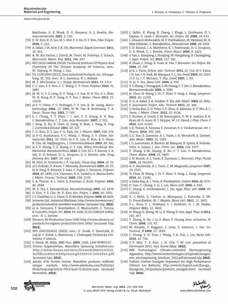
520
www.mme-journal.de
L. Persano, A. Camposeo, C. Tekmen, D. Pisignano
Matthews, G. E. Wnek, D. G. Simpson, G. L. Bowlin, Bio-macromolecules 2002, 3, 232.
[78] K. W. Kim, K. H. Lee, M. S. Khil, Y. S. Ho, H. Y. Kim, Fiber Polym.2004, 5, 122.
[79] A. Jafari, J.-H. Jeon, I.-K. Oh, Macromol. Rapid Commun. 2011,32, 921.
[80] A. M. dos Santos, J. Dierck, M. Troch, M. Podevijn, E. Schach,Macromol. Mater. Eng. 2011, 296, 637.
[81] WO 2010/148644 (2010), Technical Institute Of Physics AndChemistry Of The Chinese Academy Of Sciences, invs.:W. Dayong, H. Wang, J. Cao.
[82] US 12/852993 (2012), Zeus Industrial Products, Inc. (Orange-burg, SC, US), invs.: B. L. Anneaux, R. L. Ballard.
[83] M. T. McClendon, S. I. Stupp, Biomaterials 2012, 33, 5713.[84] C. C. Liao, S. S. Hou, C. C. Wang, C. Y. Chen, Polymer 2010, 51,
2887.[85] M. M. Li, Y. Z. Long, D. Y. Yang, J. S. Sun, H. X. Yin, Z. L. Zhao,
W. H. Kong, X. Y. Jiang, Z. Y. Fan, J. Mater. Chem. 2011, 21,13159.
[86] a) S. Y. Chew, T. C. Hufnagel, C. T. Lim, K. W. Leong, Nano-technology 2006, 17, 3880; b) W. Tan, R. Krishnaraj, T. A.Desai, Tissue Eng. 2001, 7, 203.
[87] E. J. Chong, T. T. Phan, I. J. Lim, Y. Z. Zhang, B. H. Bay,S. Ramakrishna, C. T. Lim, Acta Biomater. 2007, 3, 321.
[88] J. Zeng, X. Xu, X. Chen, Q. Liang, X. Bian, L. Yang, X. Jing,J. Controlled Release 2003, 92, 227.
[89] T. G. Kim, D. S. Lee, T. G. Park, Int. J. Pharm. 2007, 338, 276.[90] a) P.-O. Rujitanaroj, Y.-C. Wang, J. Wang, S. Y. Chew, Bio-
materials 2011, 32, 5915; b) Y. K. Luu, K. Kim, B. S. Hsiao,B. Chu, M. Hadjiargyrou, J. Controlled Release 2003, 89, 341.
[91] a) S. P. Zhong, Y. Z. Zhang, C. T. Lim, Wiley Interdiscip. Rev.Nanomed. Nanobiotechnol. 2010, 2, 510; b) C. P. Barnes, S. A.Sell, E. D. Boland, D. G. Simpson, G. L. Bowlin, Adv. DrugDelivery Rev. 2007, 59, 1413.
[92] M. Shin, H. Yoshimoto, J. P. Vacanti, Tissue Eng. 2004, 10, 33.[93] a) S. Kidoaki, K. Kwon, T. Matsuda, Biomaterials 2005, 26, 37;
b) B. Ding, E. Kimura, T. Sato, S. Fujita, S. Shiratori, Polymer2004, 45, 1895; c) A. Varesano, R. A. Carletto, G. Mazzuchetti,J. Mater. Process. Technol. 2009, 209, 5178.
[94] S. A. Theron, A. L. Yarin, E. Zussman, E. Kroll, Polymer 2005,46, 2889.
[95] W. E. Teo, S. Ramakrishna, Nanotechnology 2005, 16, 1878.[96] G. Kim, Y. S. Cho, W. D. Kim, Eur. Polym. J. 2006, 42, 2031.[97] J. S. Varabhas, G. G. Chase, D. H. Reneker, Polymer 2008, 49, 4226.[98] Inovenso Ltd., Industrial Machines, http://www.inovenso.com/
products/industrial-nanofiber-machines/ (accessed July, 2012).[99] a) A. Varesano, F. Rombaldoni, G. Mazzuchetti, C. Tonina,
R. Comotto, Polym. Int. 2010, 59, 1606; b) US 3280229 (1966),invs.: H. L. Simons.
[100] Elmarco, NS Production Lines 1600, http://www.elmarco.cz/products/ns-organic-production-lines-1600/ (accessed July,2012).
[101] WO 2005/024101 (2005), invs.: O. Jirsak, F. Sanetrnik, D.Luk,as V. Kotek, L. Martinova, J. Chaloupek (Technicka Uni-verzita V Liberci).
[102] S. Petrik, M. Maly, MRS Proc. 2009, 1240, 1240-WW03-07.[103] Dienes Apparatebau, Nanofiber Spinning Installations,
http://www.dienes.net/docs/Dienes%20Article%20-%20 Na nofiber%20Spi nni ng%202 010-10%20 en. pdf(accessed July, 2012).
[104] Adsale ATA Textile Online, Nanofiber products infiltrateunique markets, http://www.adsaleata.com/Publicity/ePub/lang-eng/article-7815/asid-72/Article.aspx (accessedNovember, 2012).
Macromol. Mater. Eng. 2
� 2013 WILEY-VCH Verlag Gmb
[105] L. Soffer, X. Wang, X. Zhang, J. Kluge, L. Dorfmann, D. L.Kaplan, G. Leisk, J. Biomater. Sci. Polym. Ed. 2008, 19, 653.
[106] L. Ghasemi-Mobarakeh, M. P. Prabhakaran, M. Morshed, M. H.Nasr-Esfahani, S. Ramakrishna, Biomaterials 2008, 29, 4532.
[107] E. D. Boland, J. A. Matthews, K. J. Pawlowski, D. G. Simpson,G. E. Wnek, G. L. Bowlin, Front. Biosci. 2004, 9, 1422.
[108] S. Yan, L. Xiaoqiang, L. Shuiping, W. Hongsheng, H. Chuanglong,J. Appl. Polym. Sci. 2010, 117, 542.
[109] B. Duan, C. Dong, X. Yuan, K. Yao, J. Biomater. Sci. Polym. Ed.2004, 15, 797.
[110] a) A. L. Yarin, Polym. Adv. Technol. 2011, 22, 310; b) V. Kalra,J. H. Lee, J. H. Park, M. Marquez, Y. L. Joo, Small 2009, 20, 2323;c) D. Li, J. T. McCann, Y. Xia, Small 2005, 1, 83.
[111] D. Li, Y. Xia, Nano Lett. 2004, 4, 933.[112] Y. Z. Zhang, J. Venugopal, Z.-M. Huang, C. T. Lim, S. Ramakrishna,
Biomacromolecules 2005, 6, 2583.[113] H. Chen, N. Wang, J. Di, Y. Zhao, Y. Song, L. Jiang, Langmuir
2010, 26, 11291.[114] D. Li, A. Babel, S. A. Jenekhe, Y. Xia, Adv. Mater. 2004, 16, 2062.[115] E. Zussmann, Polym. Adv. Technol. 2011, 22, 366.[116] S. Sinha-Ray, D. D. Pelot, Z. P. Zhou, A. Rahman, X.-F. Wu, A. L.
Yarin, J. Mater. Chem. 2012, 22, 9138.[117] Z. Kurban, A. Lovell, S. M. Bennington, D. W. K. Jenkins, K. R.
Ryan, M. O. Jones, N. T. Skipper, W. I. F. David, J. Phys. Chem. C2010, 114, 21201.
[118] S. K. Tiwari, R. Tzezana, E. Zussman, S. S. Venkatraman, Int. J.Pharm. 2010, 392, 209.
[119] Z. C. Sun, E. Zussman, A. L. Yarin, J. H. Wendorff, A. Greiner,Adv. Mater. 2003, 15, 1929.
[120] I. G. Loscertales, A. Barrero, M. Marquez, R. Spretz, R. Velarde-Ortiz, G. Larsen, J. Am. Chem. Soc. 2004, 126, 5377.
[121] Y. Zhang, Z.-M. Huang, X. Xu, C. T. Lim, S. Ramakrishna,Chem. Mater. 2004, 16, 3407.
[122] S. N. Reznik, A. L. Yarin, E. Zussman, L. Bercovici, Phys. Fluids2006, 18, 062101.
[123] A. V. Bazilevsky, A. L. Yarin, C. M. Megaridis, Langmuir 2007,23, 2311.
[124] H. Chen, N. Wang, J. Di, Y. Zhao, Y. Song, L. Jiang, Langmuir2010, 26, 11291.
[125] S. Sinha-Ray, A. L. Yarin, B. Pourdeyhimi, Carbon 2010, 48, 3575.[126] D. Sun, C. Chang, S. Li, L. Lin, Nano Lett. 2006, 6, 839.[127] C. Chang, K. Limkrailassiri, L. Lin, Appl. Phys. Lett. 2008, 93,
123111.[128] G. S. Bisht, G. Canton, A. Mirsepassi, L. Kulinsky, S. Oh,
D. Dunn-Rankin, M. J. Madou, Nano Lett. 2011, 11, 1831.[129] F.-L. Zhou, P. L. Hubbard, S. J. Eichhorn, G. J. M. Parker,
Polymer 2011, 52, 3603.[130] H. Wang, G. Zheng, W. Li, X. Wang, D. Sun, Appl. Phys. A 2011,
102, 457.[131] Y. Zhang, X. He, J. Li, Z. Miao, F. Huang, Sens. Actuators, B:
Chem. 2008, 132, 67.[132] M. Rinaldo, F. Ruggieri, L. Lozzi, S. Santucci, J. Vac. Sci.
Technol., B 2009, 27, 1829.[133] C. Chang, V. H. Tran, J. Wang, Y.-K. Fuh, L. Lin, Nano Lett.
2010, 10, 726.[134] S.-Y. Min, T. S. Kim, J. H. Cho, T.-W. Lee, presented at
Electrospin 2012, Jeju, Korea (May, 2012).[135] IME Technologies, Climate-controlled Electrospinning
Apparatus, http://www.imetechnologies.nl/uploads/images/ime_electrospinning_brochure_2012.pdf (accessed July, 2012).
[136] DuPont, DuPont Energain Separators for High PerformanceLithium Ion Batteries, http://www2.dupont.com/Energy_Storage/en_US/products/products_energain.html (accessedJuly, 2012).
013, 298, 504–520
H & Co. KGaA, Weinheim www.MaterialsViews.com