Industrial Training at Electrosteel
42
Supreme Knowledge Foundation Group of Institutions, Mankundu Electrosteel Castings Limited Haldia Works, Haldia
-
Upload
souptik-chatterjee -
Category
Documents
-
view
34 -
download
0
Transcript of Industrial Training at Electrosteel
Supreme Knowledge Foundation
Group of Institutions, Mankundu
Electrosteel Castings Limited
Haldia Works, Haldia
Industrial Training Report
Submitted by : Arvind Kumar Dhobi
Ashish Kumar Prasad
Debnirmalyo Ghosh
Krishna Choudhary
Mukul Gopal Mukherjee
Shahbaz Aslam
Shubhendu Pal
Sonu Kumar Mahato
Souptik Chatterjee
Subhadip Bera
OF
Department of Mechanical Engineering
Supreme Knowledge Foundation Group of Institutions

Acknowledgement Training at Electrosteel Castings Limited, Haldia has been very insightful and
valuable, helping us to increase our skill capability and ability to understand what we have studied so far and going to study in our engineering course. Here we gained knowledge about various processes and equipment related to the Coke Oven Plant, Sponge Iron Plant and well as Thermal Power Plant.
We would like to take this opportunity to express our feelings of gratitude & respect towards the people at Electrosteel Castings Limited, Haldia who have always helped & guided us in understanding various concepts, which were previously unknown to us.
First of all, we would like thank Mr. Piyush Khila, Manager (HR Division) for providing us such a fruitful opportunity to have a firsthand industrial visit to ECL Plant. After that, we would like to thank Mr. Biplob Gorai, HOD (M.E), who helped us a lot in understanding the basic know-hows of the plant process. We would like to thank Mr. Tarun Kumar Das, (Incharge of Power Plant), Ms. Nabanita Das & Mr. Jahangir Hussain, (Incharge of DM Plant), and Mr. Satra (Of Sponge Iron Plant) for guiding us at different Mechanical and Instrumental aspects of the Plant in our journey.
Last but not the least, we would love to thank our Head of the Department, Prof. Swarup Mukherjee for giving us such a golden opportunity for the real industrial visit. Thanking you all ! Trainee Students
Dept. of Mechanical Engineering

Electrosteel Castings Limited – An Overview
At Electrosteel Castings, the focus is always on continuous improvement when it comes to organizational quality and performance with the objective of improving customer satisfaction evolving the product portfolio. Customers are becoming more and more conscious not only regarding the value of the product but also demanding compliance of social and environmental issue prevailing at the premises of the manufacturer. Company is constantly upgrading its processes and has undertaken several initiatives to enhance its position of leadership by offering quality products and services.
Achievements
Some of the recent achievements in this direction include –
TPM and Kaizen Culture have percolated, both upward and downward and continue to be maintained with all the enthusiasm involving and motivating personnel at all the levels. TPM excellence award achieved by Khardah works has further motivated the teams to take up the challenge of competing with the best in the industry worldwide.
The Company has achieved the French NF approval for its products for several applications.
The Company continues to maintain the approval of its quality system and products by agencies like DVGW (Germany), BSI (UK), SIRIM (Malaysia), Middle East and approval from USA Certifying agencies.
At the core of its policy for Corporate Social Responsibility, the Company undertakes a range of activities to improve living conditions in its operational areas. It also conducts regular training programs to create awareness regarding health, hygiene and safety among the people.
ECL at Haldia Works
Electrosteel has established a 12 MW Power Plant at Haldia as a Clean Development Mechanism (CDM) project, the sensible heat in the waste gas emissions from the Coke Oven and the Sponge Iron Plant is utilized for power generation, saving approximately 78,000 MT of Carbon Dioxide emissions to atmosphere every year. The Haldia project is registered as a CDM project with UNFCCC (United Nations Framework Convention for Climate Change) under Kyoto Protocol. 92% of the Waste Water at the Company’s plant is recycled and reused.
History
1955 – The Company was incorporated on 26th November, at Rajgangpur. The Company Manufactured Steel Castings, Grinding media & Spun-Cast iron pipes.
1965 – Towards the end of the year, the name of Company was changed from Dalmia Iron and Steel Ltd. To Electrosteel Castings Ltd.
1968 – The Company undertook to set up a new integrated electrical steel melting shop & wire rod mills in Ghaziabad, U.P. at a cost of about Rs 2 crores.
1987 – There was a fall in the production in pipes mainly due to non-availability of raw material resulting in frequent stoppage of production.
1988 – During the year, the Company undertook to set up a new unit at Khardah for production of ductile iron pipes with an annual capacity of 60,000 tonnes per annum.
1994 – A new Ductile Iron Pipe plant was being set up at Elavur with an installed capacity of 30,000 tonnes of D.I. pipes per annum.
1996 – The Company proposed to put up a pig iron plant at Khardah where the pipe plants are located at an estimated capital cost of Rs 55 crores. It is also proposed to provide facilities at Elavur plant for making Ductile iron pipes in addition to the current production of cast iron pipes at an estimated cost of Rs 20 crores.
1997 – The Company had a technical collaboration with Luitpoldhut AG and technocomplex GmbH, both of Germany who have provided the technical basic manufacturing & process know how with technology for molding and annealing D.I. and C.I. pipes. The Company engaged in the manufacture of Cast Iron & Ductile Iron pipes at its plant in Khardah in West Bengal.

- A forty year old Company manufacturing Ductile Iron (DIs) & Cast Iron (Cis) pipes. Electrosteel Castings Ltd. is the only Indian manufacturer of DI spun pipes conforming to International Standards.
- The Company proposes to set up its manufacturing facilities for Ductile Iron pipe in Gujrat.
1998 – Electrosteel Castings Ltd. one of the largest manufacturer of cast iron pipes in the country, has decided to relocate its Rs 55 crore ductile iron pipe (DIPs) project from Elavur in Tamil Nadu to Kolhapur in Maharashtra. The Elavur unit currently manufactures cast iron pipes.
2003 – Electrosteel Castings Ltd. has enhanced its presence in the European market through setting up a wholly owned subsidiary in Spain. Electrosteel Castings Board has approved for setting up a Coke Oven Plant at Haldia with a capacity of 35,000 tonnes per annum along with a capacity of 150,000 tonnes of coke per annum.
Coke Oven Plant (COP) Introduction: From the name we can easily say the main objective of the COP is to produce coke. Coke is produced from a special type of coal which is Bituminous coal. The whole process for making Coke from bituminous coal is done in the COP. There are four batteries in the ECL, Haldia works. One battery is made by two blocks. Each block consists of 17 ovens. First and second battery are connected with the boiler 1 and boiler 2 of the CPP. Other are free to environmental. Here the raw material is the bituminous cake and the final product is the cake. The byproduct of making coke is the flue gas. This is a very hot gas. This flue gas's heat is to produce power in the CPP.
The Beehive Coke Oven:
A fire brick chamber shaped like a dome is used, commonly known as a beehive oven. It is typically between 4 meters wide and 2.5 meters high. In past time its roof has a hole for charging the coal or other kindling from the top. The discharging hole for charging the coal or other kindling from the top. The discharging car hole is provided in the circumference of the lower part of the wall. But nowadays charging car and discharging car is used to charge and discharge the coke oven respectively. In a coke oven battery, a number of ovens are built in a row with common walls between neighboring ovens. A batter consisted of a great many ovens, sometimes hundreds of ovens, in a row.
Air is supplied initially to ignite the coal. Carbonization proceeds from top to bottom and is completed in two to three days. Heat is supplied by the burning volatile matter so no by-products are recovered. The exhaust gases are allowed to escape to atmosphere. The hot coke is quenched with water and discharged, manually through the side door. The walls and roof retain enough heat to initiate Carbonization of the next charge.
When coal was burned in a coke oven, the impurities of the coal not already driven off as gases accumulated to from slag, which was effectively a conglomeration of the removed impurities. Since it was not the desired coke product, slag was initially nothing more than an unwanted by-product and was discarded. Later, however, it was found to have many beneficial uses and has since been used as an ingredient in brick-making, mixed cement, granule - covered shingles, and even as a fertilizer.
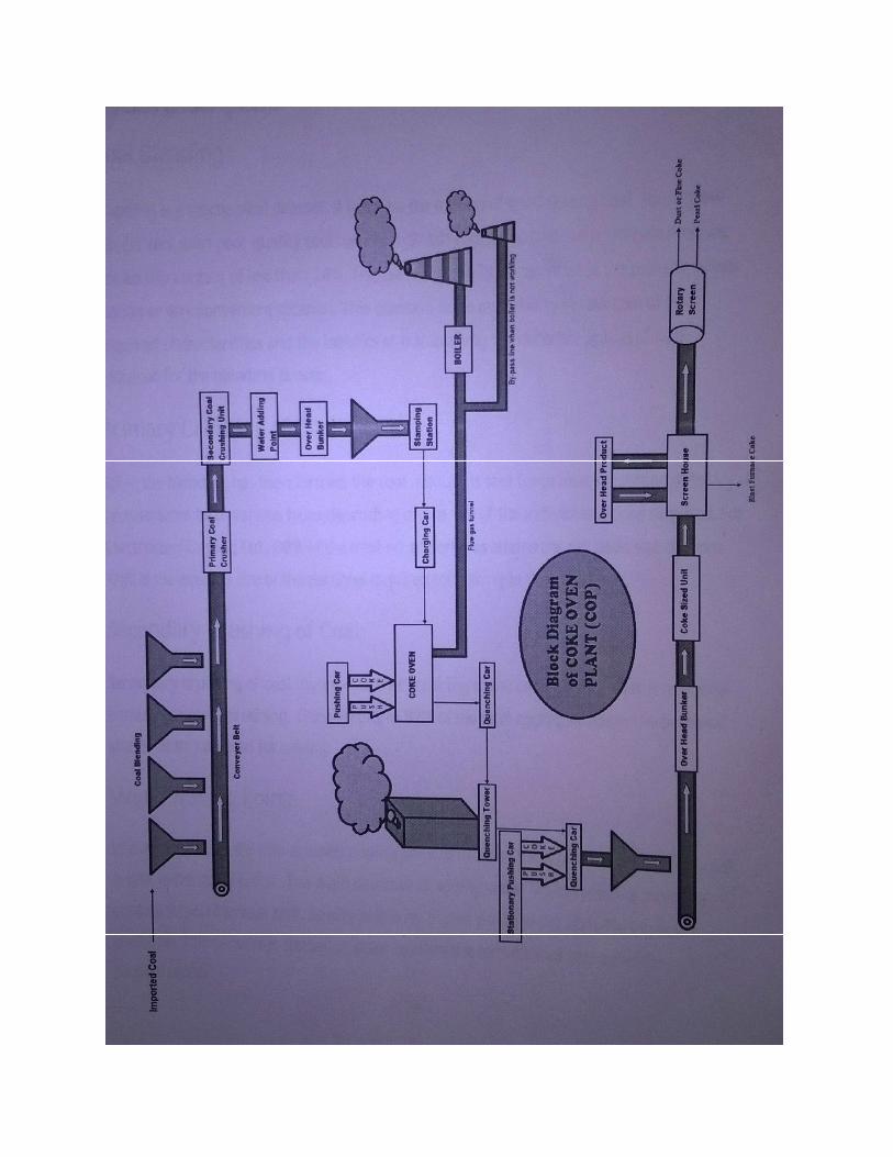
Process Description
Coal Blenching:
Blending is a mechanical process l. It involves the mixing of good quality coal having low ash content with poor quality coal having high ash content so that the aggregate mixture has an ash content of less than 34%. This blending can be done either at the pitched, power station or any convenient location. This question is the availability of raw coal of the required characteristics and the logistics of transporting the different grades of coal required for the blending process.
Primary crushing of coal:
After the blending has been formed, the coal mixture is sent for primary crushing. Primary crushers can be of various types depending on the size of the individual grains required. For Electro steel Casting Ltd., 88% of the total no. of particles attains the net basic size of 3 mm. This is the average size of the particle required for coking in the coke oven.
Secondary crushing of coal:
Secondary crushing of coal involves further crushing of the coal mixture after it has gone through primary crushing. These result in 97% of the total aggregate attain the net basic size of 3mm required for coking.
Water adding point:
Water is added to the coal at water adding point to increase the moisture content. The coal is sent to the coal bunker. The main objective of adding water is increase bulk density that is for higher productivity and offering less pollution. This process is applied in order to allow the formation of coal cakes for carbonization.
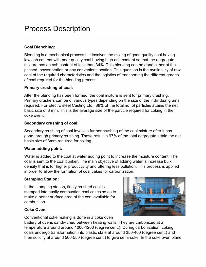
Stamping Station:
In the stamping station, finely crushed coal is stamped into easily combustion coal cakes so as to make a better surface area of the coal available for combustion.
Coke Oven:
Conventional coke making is done in a coke oven battery of ovens sandwiched between heating walls. They are carbonized at a temperature around around 1000-1200 (degree cent.). During carbonization, coking coals undergo transformation into plastic state at around 350-400 (degree cent.) and then solidify at around 500-550 (degree cent.) to give semi-coke. In the coke oven plane
at ECL- Haldia, there are 4 batteries. Each of the battery has two slots. The first 3 batteries contains 34 ovens each i.e. each slots. The last battery has 30 oven I.e. Each slot contain 15 oven.
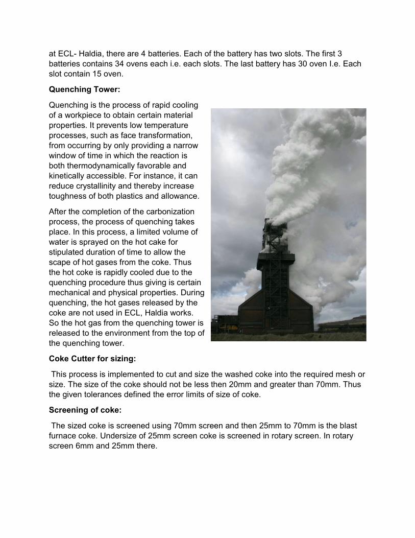
Quenching Tower:
Quenching is the process of rapid cooling of a workpiece to obtain certain material properties. It prevents low temperature processes, such as face transformation, from occurring by only providing a narrow window of time in which the reaction is both thermodynamically favorable and kinetically accessible. For instance, it can reduce crystallinity and thereby increase toughness of both plastics and allowance.
After the completion of the carbonization process, the process of quenching takes place. In this process, a limited volume of water is sprayed on the hot cake for stipulated duration of time to allow the scape of hot gases from the coke. Thus the hot coke is rapidly cooled due to the quenching procedure thus giving is certain mechanical and physical properties. During quenching, the hot gases released by the coke are not used in ECL, Haldia works. So the hot gas from the quenching tower is released to the environment from the top of the quenching tower.
Coke Cutter for sizing:
This process is implemented to cut and size the washed coke into the required mesh or size. The size of the coke should not be less then 20mm and greater than 70mm. Thus the given tolerances defined the error limits of size of coke.
Screening of coke:
The sized coke is screened using 70mm screen and then 25mm to 70mm is the blast furnace coke. Undersize of 25mm screen coke is screened in rotary screen. In rotary screen 6mm and 25mm there.
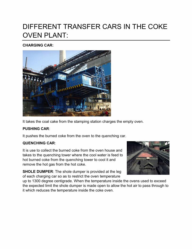
DIFFERENT TRANSFER CARS IN THE COKE OVEN PLANT: CHARGING CAR:
It takes the coal cake from the stamping station charges the empty oven.
PUSHING CAR:
It pushes the burned coke from the oven to the quenching car.
QUENCHING CAR:
It is use to collect the burned coke from the oven house and takes to the quenching tower where the cool water is feed to hot burned coke from the quenching tower to cool it and remove the hot gas from the hot coke.
SHOLE DUMPER: The shole dumper is provided at the leg of each charging car so as to restrict the oven temperature up to 1300 degree centigrade. When the temperature inside the ovens used to exceed the expected limit the shole dumper is made open to allow the hot air to pass through to it which reduces the temperature inside the coke oven.
INSTRUMENTS USED IN THE COKE OVEN PLANT
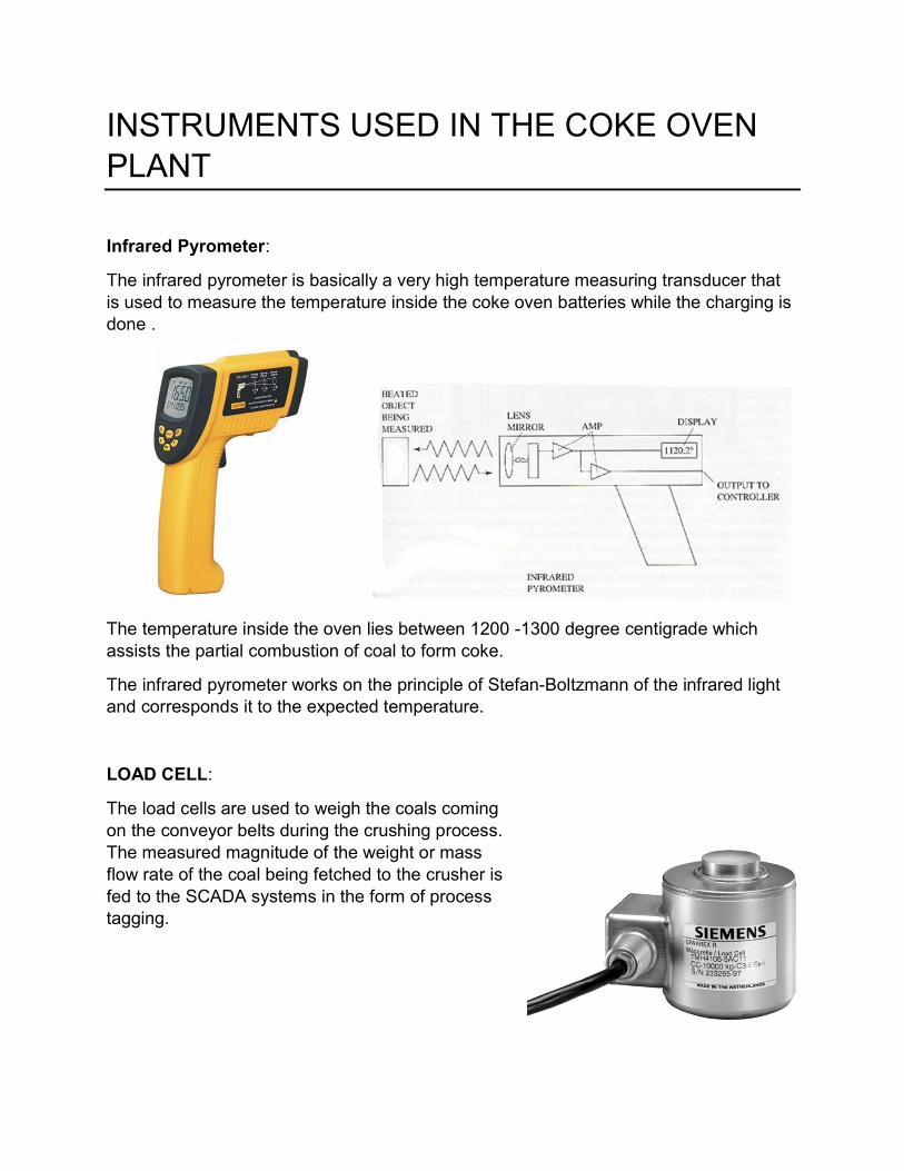
Infrared Pyrometer:
The infrared pyrometer is basically a very high temperature measuring transducer that is used to measure the temperature inside the coke oven batteries while the charging is done .
The temperature inside the oven lies between 1200 -1300 degree centigrade which assists the partial combustion of coal to form coke.
The infrared pyrometer works on the principle of Stefan-Boltzmann of the infrared light and corresponds it to the expected temperature.
LOAD CELL:
The load cells are used to weigh the coals coming on the conveyor belts during the crushing process. The measured magnitude of the weight or mass flow rate of the coal being fetched to the crusher is fed to the SCADA systems in the form of process tagging.
Sponge Iron Plant (SIP)
Introduction
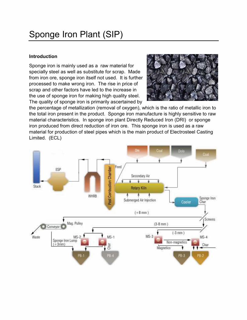
Sponge iron is mainly used as a raw material for specially steel as well as substitute for scrap. Made from iron ore, sponge iron itself not used. It is further processed to make wrong iron. The rise in price of scrap and other factors have led to the increase in the use of sponge iron for making high quality steel. The quality of sponge iron is primarily ascertained by the percentage of metallization (removal of oxygen), which is the ratio of metallic iron to the total iron present in the product. Sponge iron manufacture is highly sensitive to raw material characteristics. In sponge iron plant Directly Reduced Iron (DRI) or sponge iron produced from direct reduction of iron ore. This sponge iron is used as a raw material for production of steel pipes which is the main product of Electrosteel Casting Limited. (ECL)

Sponge Iron:
Sponge iron is a metallic product produced through direct reduction of iron ore in the solid state. It is a substitute for scrap and is mainly used in making steel through the secondary route. The process of sponge iron making aims to remove the oxygen from iron ore.the quality of sponge iron primarily ascertained by the percentage of metallization, which is the ratio of metallic iron present in the product.
Sponge iron manufacture is highly sensitive to raw material characteristics. Therefore, it is essential to examine the chemical and physical characteristics of raw materials, both individually and in combination. The basic raw materials for the production of sponge iron are iron ore, non-coking coal and dolomite. Sizing of raw materials also play vital role in sponge iron manufacturing process. The required size of iron ore, MPS, its physical properties like T.I, A.I, & chemical properties like Fe, LOI, gangue content
In Iron Process, two types of coal are being used such as feed coal and injection coal.
PROPERTIES OF SPONGE IRON
High iron content and high degree of metallization Uniform and consist quality Lower Sulphur and phosphorus content Negligible tramp element Minimum dust generation during material handling.
Process Description:
For the direct reduction of iron ore the main furnace used is Rotary kiln. The Rotary kiln is the refractory line cylindrical vessel on which blowers are mounted and the air pipes to provide combustion air to the inside of the kiln. During lite up there is a startup burner at the kiln discharge end which is oil fired to heat up the Rotary kiln. To ignite the injected coal from outlet of the kiln. When the Desired temperature is reached Iron ore, coal and limestone or dolomite are fed from kiln feed and also coal is injected from kiln discharge end.
The startup burner which uses oil for initial heat up is withdrawn after getting the ignition temperature of the injected coal. Now the coal if the desired temperature for reduction process is obtained, iron ore with dolomite is fed from inlet of the kiln. Since the kiln has a downward slope of 2.5 % from the feed end side to discharge end side, its rotation causes the iron ore and coal to mix and travel to the system.
The rotational speed of the kiln is adjustable as per the feed rate and percentage of metallization. The percentage of inclination, rotational speed the length of the kiln and time the material is exposed to the reducing agent CO, the temperature all to be taken into consideration the kiln has three functions.
It has a heat exchanger It is a vessel for chemical reaction It is conveyor of solids.
That following reaction take place inside the kiln.
C+O2=CO2;
CO2+C=2CO;
The above reaction is known as bound ward reaction which is reversible.
fe2O3+CO=fe3O4+CO2;
fe3O4+CO=feO+CO2;
FeO+CO=Fe (Metallic)+CO2;
However the reduction form oxide to metal does not occurs in one step but by
A gradual removal of oxygen giving rise to various intermediate oxides the
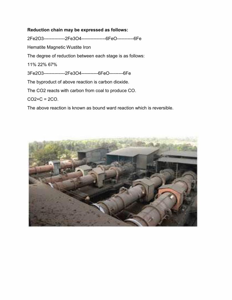
Reduction chain may be expressed as follows:
2Fe2O3--------------2Fe3O4----------------6FeO-----------6Fe
Hematite Magnetic Wustite Iron
The degree of reduction between each stage is as follows:
11% 22% 67%
3Fe2O3--------------2Fe3O4-----------6FeO---------6Fe
The byproduct of above reaction is carbon dioxide.
The CO2 reacts with carbon from coal to produce CO.
CO2+C = 2CO.
The above reaction is known as bound ward reaction which is reversible.

RAW MATERIALS FOR SPONGE IRON MAKING
Coal
Important factors determining coal quality are:
Chemical properties such as fixed carbon, ash content, volatile matter, etc; & Physical properties viz., reactivity and fusion temperature.
Iron Ore
In sponge iron making, iron ore is reduced in solid state. Unlike in the conventional steel melting process, the gangue content if iron ore cannot be separated as a slag. Therefore it becomes imperative to select with a high Fe content and a low gangue content, to optimize yield during steel making. Apart from this to ensure a better kiln campaign life and output, the iron is subjected to undergo a series of other tests viz shatter, tumbler& abrasion indices reducibility etc.at present iron ore pellet is used in the DRI section.
DOLOMITE
Dolomite acts in the process as a desulphuriser, removing sulphur from the feed mix during the reduction process.it is mixed in small proportion along with other raw materials before charging into the kiln.
Thermal Power Plant at ECL, Haldia
(12 MW) Introduction:
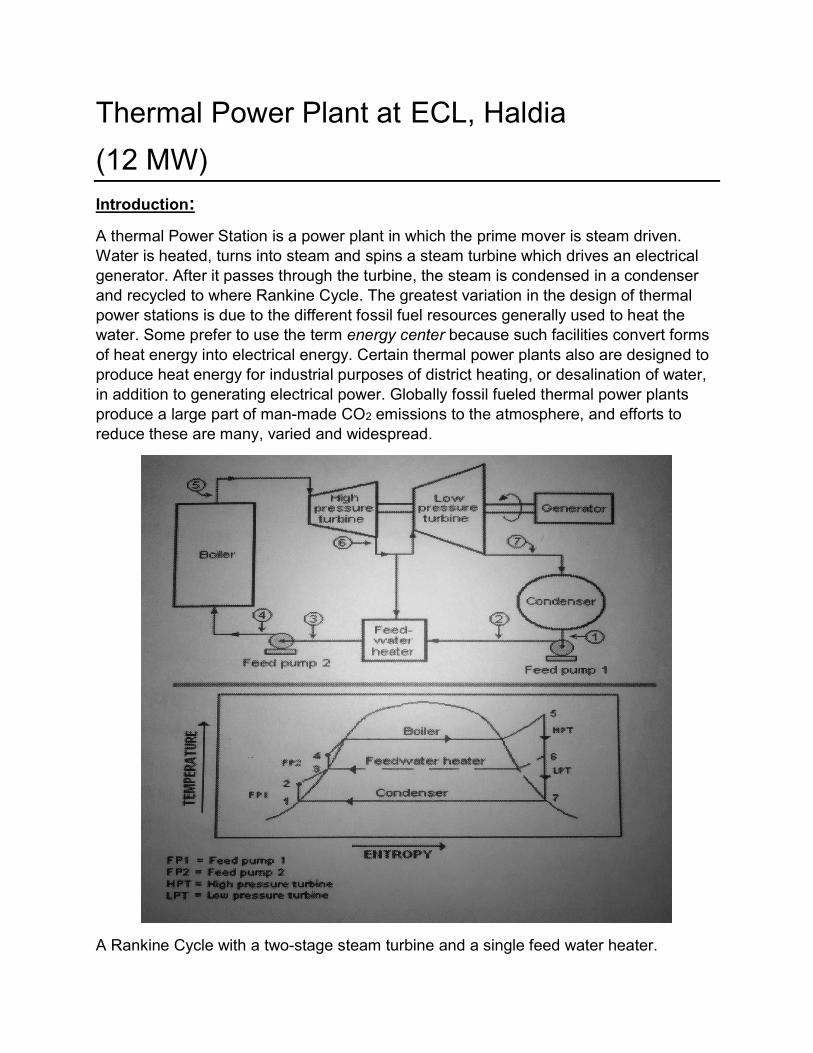
A thermal Power Station is a power plant in which the prime mover is steam driven. Water is heated, turns into steam and spins a steam turbine which drives an electrical generator. After it passes through the turbine, the steam is condensed in a condenser and recycled to where Rankine Cycle. The greatest variation in the design of thermal power stations is due to the different fossil fuel resources generally used to heat the water. Some prefer to use the term energy center because such facilities convert forms of heat energy into electrical energy. Certain thermal power plants also are designed to produce heat energy for industrial purposes of district heating, or desalination of water, in addition to generating electrical power. Globally fossil fueled thermal power plants produce a large part of man-made CO2 emissions to the atmosphere, and efforts to reduce these are many, varied and widespread.
A Rankine Cycle with a two-stage steam turbine and a single feed water heater.

The energy efficiency of a conventional thermal power station, considered salable energy produced as a percent of the heating value of the fuel consumed, its typically 33% to 48%. As with all heat engines, their efficiency is limited, and governed by the laws of thermodynamics.
Electrosteel has commissioned a 12 MW power plant at Haldia, which generates power using the waste gas of Coke Oven Plant and Sponge Iron Plant and supplies into West Bengal State Electricity Distribution Corporation Limited (WBSEDCL). The plant itself uses about 2 MW of the produced electricity for the functioning of its Coke Oven Plant and Sponge Iron Plant and supplies the rest (about 10 MW) to the Grid. The power plant has two distinct power transformer for this sake (11KV : 33KV step up & 11KV : 440V step down). Haldia’s 12 MW based power plant has been developed as a Clean Development Mechanism (CDM) project since waste gasses are used instead of burning fossil fuels for power making. This project will reduce appx. 78000 MT of CO2 emissions to the atmosphere every year, thus helping in erratic climate changes.

Rankine’s Cycle The Thermal (Steam) Power Plant uses a dual (Vapour + Liquid) phase cycle. It is a closed cycle to enable the working fluid (Water) to be used again and again. The cycle used is “Rankine Cycle” modified to include super heating of steam, re-generative feed water heating and re-heating of steam of figure above shows this cycle and its self-explanatory. On large turbines, it becomes economical to increase the cycle efficiency by using reheat, which is a way of partially overcoming temperature limitations. By returning partially expanded steam, to reheat, the average temperature at which heat is added, is increased and, by expanding this reheated steam to the remaining stages of the turbine, the exhaust wetness is considerably less than it would otherwise be conversely, if the maximum tolerable wetness is allowed, the initial pressure of the steam can be appreciably increased.
Bleed Steam extraction. For regenerative system, nos. of non-regulated extractions are taken from HP, IP Turbine.
Regenerative heating of the boiler feed water is widely used in modern power plants; the effects being to increase the average temperature at which heat is added to the cycle, thus improving the cycle efficiency.
Factors Affecting Thermal Cycle Efficiency
The Thermal Efficiency is affected by following
Initial Steam Pressure Initial Steam Temperature Whether reheat is used or not, and if used reheat pressure & temperature Condenser Pressure Regenerative feed water heating
Non-condensing or back pressure turbine are most widely used for process steam applications. exhaust pressure is controlled by a regulating valve to suit the needs of the process steam pressure. There are commonly found at refineries, district heating unit, pulp and paper plant, are desalination facilities where large amounts of low pressure process steam are available.
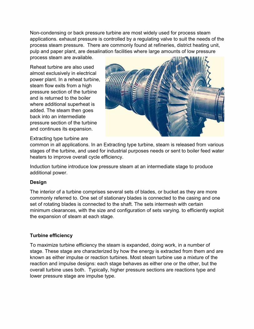
Reheat turbine are also used almost exclusively in electrical power plant. In a reheat turbine, steam flow exits from a high pressure section of the turbine and is returned to the boiler where additional superheat is added. The steam then goes back into an intermediate pressure section of the turbine and continues its expansion.
Extracting type turbine are common in all applications. In an Extracting type turbine, steam is released from various stages of the turbine, and used for industrial purposes needs or sent to boiler feed water heaters to improve overall cycle efficiency.
Induction turbine introduce low pressure steam at an intermediate stage to produce additional power.
Design
The interior of a turbine comprises several sets of blades, or bucket as they are more commonly referred to. One set of stationary blades is connected to the casing and one set of rotating blades is connected to the shaft. The sets intermesh with certain minimum clearances, with the size and configuration of sets varying. to efficiently exploit the expansion of steam at each stage.
Turbine efficiency
To maximize turbine efficiency the steam is expanded, doing work, in a number of stage. These stage are characterized by how the energy is extracted from them and are known as either impulse or reaction turbines. Most steam turbine use a mixture of the reaction and impulse designs: each stage behaves as either one or the other, but the overall turbine uses both. Typically, higher pressure sections are reactions type and lower pressure stage are impulse type.
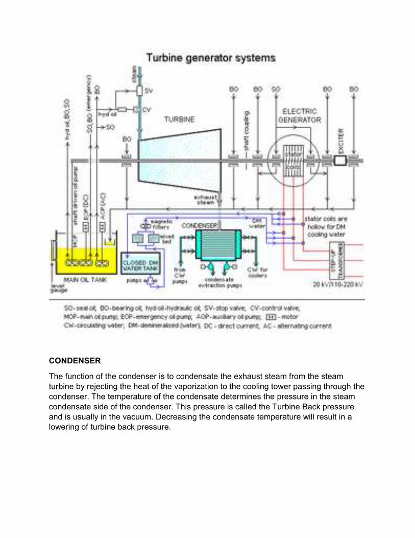
CONDENSER
The function of the condenser is to condensate the exhaust steam from the steam turbine by rejecting the heat of the vaporization to the cooling tower passing through the condenser. The temperature of the condensate determines the pressure in the steam condensate side of the condenser. This pressure is called the Turbine Back pressure and is usually in the vacuum. Decreasing the condensate temperature will result in a lowering of turbine back pressure.

DEAERATOR
A deaerator is a device that is widely used for the removal of oxygen and other dissolve gases from the feed water to steam-generating boilers. In particular, dissolve oxygen in boiler feed waters. will cause serious corrosion damage in steam systems by attaching to the walls of metal piping and other metallic equipment and. forming oxides(rust). Dissolved carbon dioxide combines with water to form carbonic acid that causes further corrosion. Most deaerators are designed to remove. Oxygen down to levels of 7 ppb by weight (0.005 cm^3/L) or less as essentially eliminating carbon dioxide.
There are two types of dearators: The Tray Type
It includes a vertical domed dearation section mounted on top of a horizontal cylindrical vessel which serves as the dearator boiler feed water storage tank.
The Spray Type
It consists only of a horizontal or vertical cylindrical vessel which serves as both the dearation section and the boiler feed water storage tank.
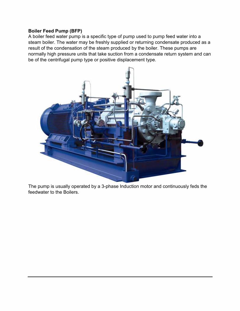
Boiler Feed Pump (BFP) A boiler feed water pump is a specific type of pump used to pump feed water into a steam boiler. The water may be freshly supplied or returning condensate produced as a result of the condensation of the steam produced by the boiler. These pumps are normally high pressure units that take suction from a condensate return system and can be of the centrifugal pump type or positive displacement type.
The pump is usually operated by a 3-phase Induction motor and continuously feds the feedwater to the Boilers.

Construction and operation
Feed water pumps range in size up to many horsepower and the electronic motor is usually separate from the pump body by some from of mechanical coupling. Large industrial condensate pumps may also serve as the feed water pump. In either case, to force the water into the boiler, the pump must generate sufficient pressure to overcome the steam pressure developed by the boiler. This is usually accomplished through the use of a centrifugal pump. Feed water pumps sometimes run intermittently and are controlled by a float switch or other similar level-sensing device energizing the pump when it detects a lowered liquid level in the boiler. The pump then runs until the level of liquid in the boiler is substantially increased. Some pump contain a two-stage switch. As liquid lowers to the trigger point of the first stage, the pump is activated. If the liquid continues to drop (perhaps because the pump has failed, its supply has been cut off or exhausted, or its discharge is blocked), the second stage will be triggered. This stage may switch off the boiler equipment, trigger an alarm, or both.

Step 3. Conversion of Mechanical Energy into Electrical Energy Generator Working Principle The A.C Generator or alternator is based upon the principle of electromagnetic induction and consists of stationary part called Stator & rotating part called Rotor. The armature windings are placed in the stator. Field winding is placed in the Rotor & DC supply is given to the field winding. When rotor is rotated, the lines of magnetic flux (viz magnetic field) cut through the stator windings. This includes an electromagnetic force (e.m.f) in the stator windings. Generator Components
1. Stator
2. Stator Windings
3. Rotor
4. Rotor Windings
Diesel Generator (DG) Room: It is used for extreme condition, when there is no power coming from power plant or WBSEDCL It is generally used for running the induction motor and cooling pump in the sponge Iron Plant.
Working Principle
It is used to convert mechanical energy into electrical energy. The energy conversion is based on the principle of production of dynamically induced emf. Whenever a conductor cuts magnetic flux dynamically induced emf is produced in it according to the Faraday's Law of electromagnetic induction.
This emf causes a current to flow if the conductor circuit is closed
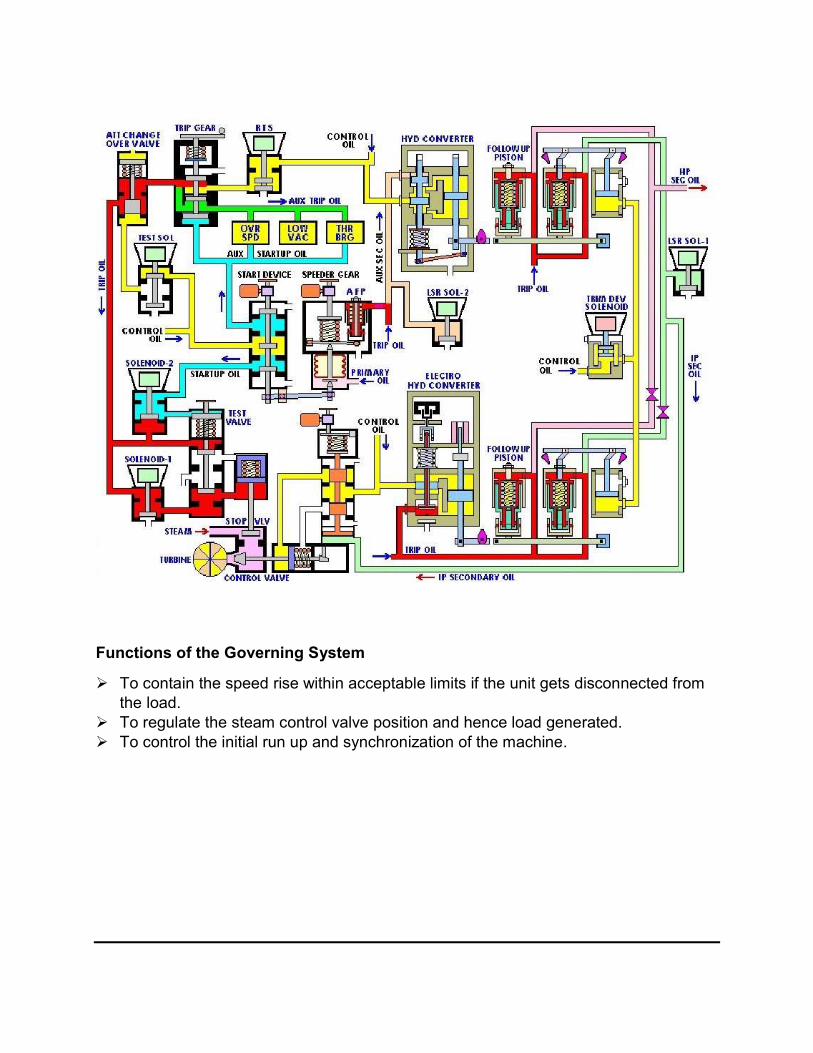
Functions of the Governing System
To contain the speed rise within acceptable limits if the unit gets disconnected from the load.
To regulate the steam control valve position and hence load generated. To control the initial run up and synchronization of the machine.
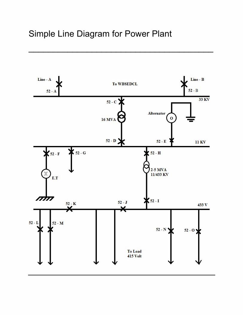
Simple Line Diagram for Power Plant
______________________________________

Demineralized Water (DM) Treatment Plant Demineralized water also known as deionized water, water that has its mineral ions removed. Mineral ions such as actions if sodium iron copper etc. And anions such as chloride, sulphite nitrate etc. are common in water. Deionization is a physical process which uses specially a manufactured ion exchange resins which provides ion exchange site for the replacement of the mineral salts I water. Because the majority of water impurities are dissolved salts, deionization produces a high purity water that is generally similar to distilled water. And this process is quick and without scale buildup.
Demineralization is process of removing mineral salts from water by using iron exchange process.
Demineralized water is water completely free of dissolved minerals as a result of one of the following process
Distillation Deionization electrodyalisis or other technologies.
Demineralized water system finds wide application In the field power, process and cooling.
Principle
Raw water is passed via two small polystyrene bead filled beds while the actions get exchanged with hydrogen ions in 1st bed the anions are exchanged with hydroxyl ions, in the second one.

Process
In the context of water purification, ion -exchange is a rapid and reversible process in which impurity ions present in the water are replaced by ions exchange resin. The impurity ions are taken up by the resin, which must be periodically regenerated to restore it to the original ionic form. Positively- charged ions are called actions and are usually metals; negatively- charged ions are called anions and usually nonmetals.
The following ions are widely found in raw waters:
Cations
Calcium
Magnesium
Sodium
Potassium
Anions
Chloride
Bicarbonate
Ion Exchange Resins:
There are 2 basic types of resin action exchange resins. Action exchange resins will release H+ ions or other positively charged ions in exchange for impurity actions present in the water. Anion exchange resins will release OH- ions or other negatively charged ions in exchange for impurity anions present in water.
The application of ion exchange to water treatment and purification. There are 3 ways in which ion exchange technology can be used in water treatment and:
1st cation exchange resins alone can be employed to soften water by base exchange; secondly, anions exchange resins alone can be used for organic scavenging and 3rd ly combinations of action exchange and anions resins can be used to remove virtually all ionic impurities present in feed water, a process known as deionization. Water deionizers purification process result in water of exceptionally high quality
Deionization
For many laboratory and industrial applications, high purity water which is essentially free from ionic contaminants is required. Water of this quality can be produced by deionization. The two most common types of deionization are:
Two- bed deionization Mixed bed deionization
Two- bed deionization:
The two bed deionizer consists of 2 vessels one containing a action exchange resin in the OH- form. Water flows through the action column, whereupon all the actions are exchanged for hydrogen ions. To keep the water electrically balanced, for every monovalent cation.one hydrogen ion is exchanged and for every divalent cation, two hydrogen ions are exchanged. The same principle applies when considering anions exchange. The decationised water then flows through the anions columns. This time all negatively charged ions are exchanged for hydroxide ions which then combine with the hydrogen ions to form water.
Mixed bed deionization:
In mixed bed deionizers the action exchange and anion exchange resins are intimately mixed and contained in a single pressure vessel. As a result the water quality obtained from a mixed bed deionized is appreciably higher than produced by a 2 bed plant.
Mixed bed deionizers are normally used to polish the water to higher levels of purity after it has been initially treated by either a two bed deionized or a reverse osmosis unit.
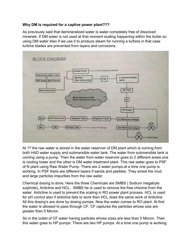
Why DM is required for a captive power plant???
As previously said that demineralized water is water completely free of dissolved minerals. If DM water is not used at that moment scaling happening within the boiler.so using DM water Also if we use it to produce steam for running a turbine in that case turbine blades are prevented from layers and corrosions.
At 1st the raw water is stored in the water reservoir of DM plant which is coming from both HAD water supply and submersible water tank. The water from submersible tank is coming using a pump. Then the water from water reservoir goes to 2 different areas.one is cooling tower and the other is DM water treatment plant. This raw water goes to PSF of N plant using Raw Water Pump. There are 2 water pumps.at a time one pump is working. In PSF there are different layers if sands and pebbles. They arrest the mud and large particles impurities from the raw water.
Chemical dosing is done. Here the three Chemicals are SMBS ( Sodium megabyte sulphide), Anticline and HCL. SMBS he is used to remove the free chlorine from the water. Anticline is used to prevent the scaling in RO power plant process. HCL is used for pH control also if anticline fails to work then HCL does the same work of Anticline. All this dosing’s are done by dosing pumps. Now the water comes to RO plant. At first the water is allowed to pass through CF. CF captures the particles whose size are greater than 5 Micron.
So in the outlet of CF water having particles whose sizes are less than 5 Micron. Then this water goes to HP pumps. There are two HP pumps. At a time one pump is working.
The outlet of HP pump goes to the membrane system. There are two stages in the membrane system. In the first stage of membrane system the particles having size less than 5 Micron are captured. The first stage membrane system has two outlets. One outlet goes to the second stage membrane system. From the second stage some water is rejected and some water goes to the HP pump suction side. This is known as recirculation and the other outlet of the first stage goes to the inlet of Degasser Tower. There are two part in this tower. In the above part there are polypropylene Pall rings and in the below part is air blower. There is a small gap on this tower. The small gap help to remove the CO2. Finally the water from this Tower store in the Degasser Tank. Actually it can be said directly that the RO plant production water is stored in the Degasser Tank. TDS (total dissolved solid) and the alkality is low by the RO plant process. Water from the Degasser tank goes to the SAC tank. Then the outlet of SBA goes to the inlet of MB tank. In MB both positive and negative ion is removed. Different kinds of resins are present in all SBA, SAC and MB tank. From this tank the DM water goes to the different portion of the plant where DM water is required.
An air blower is used to remove the scaling in the PSF tank. That technique is known as backwash. When this is done at that time the outlet water of the PSF does not go to the actual process of the DM and RO plant but the dirt (I.e. Scaling)are come out with the raw
Water to the drain from the PSF tank.at this time the plant is running with the help of the
Storage water of Degassed tank.
A totalizer is used to show the total amount of water production.in this plant DM
Water is produced with the rate of 4000ilr/hr.
A conductivity meter is used to measure the conductivity of the water. Also Ph meter is
Used to show the PH of the DM water after Morph Olin chemical dosing.
Also various type of instruments are used to detect the pressure, flow, level in the process.
Rotameter is used to measure the flow of inlet water of SAC and SBA tank or Bed. A pressure
Gauge is used to measure the flow (in terms of differential pressure across an orifice plate)
Of water in the process. Also pressure gauge is used to measure the pressure of air in the
Outlet of air -blower. Sight Glasses are used to measure the water level in various tanks.
Sometimes pressure gauge is used to measure the level of water in tank.

Instruments used in DM Water Plant
TOTALISER
A flow indicator totalizer is a device that measures electrical signal from a flow sensing device flow sensor. The electrical signal can be 4-20 mA or 12vdc/ 24vdc pulse type. A flow indicator totalizer scales this signal in terms of M^3/ Hr, Klr/Hr, Kg/Hr etc. And displays it. This is an instantaneous flow rate.
Now a day’s most of the flow indicator totalizer are microcontroller based. They have facilities of serial communication to connect the SCADA/PLC/DCS relay output based of flow rate of totalizer, totalizer reset retransmission of flowrate signal to other devices. Flow totalizer accept signal from various types of flow metre like ultrasonic, electromagnetic,
differential Pressure transmitter and orifice plate turbine type etc.
CONDUCTIVITY METER
An electrical conductivity metre measures the electrical conductivity in a solution. Commonly used in hydroponics aquaculture and freshwater system to monitor the amount of nutrients, salt of impurities in the water.
PRINCIPLE OF OPERATION
The common laboratory conductivity measures employ a potentiometric method and four electrodes. Often the electrodes are cylindrical and arranged concentrically. The electrodes are usually made of platinum metal. An alternating current is applied to the outer pair of the electrodes. The potential between the inner pair is measured. Conductivity could in principle be determined using the distance between the electrodes and their surface area using the Ohm’s law but generally, for accuracy, a calibrations employed using electrolytes.
Of well-known conductivity. Industrial conductivity probes often employ an inductive method, which has the advantage. That the fluid does not wet the electrical parts of the sensor. Here, two inductively-coupled coils are used. One is the driving coil producing a magnetic field and It is supplied with accurately-know voltage. The Other forms a secondary coil of a transformer. The Liquid passing through a channel in the sensor forms One turn in the secondary winding of the transformer. The induced current is the output of the sensor.
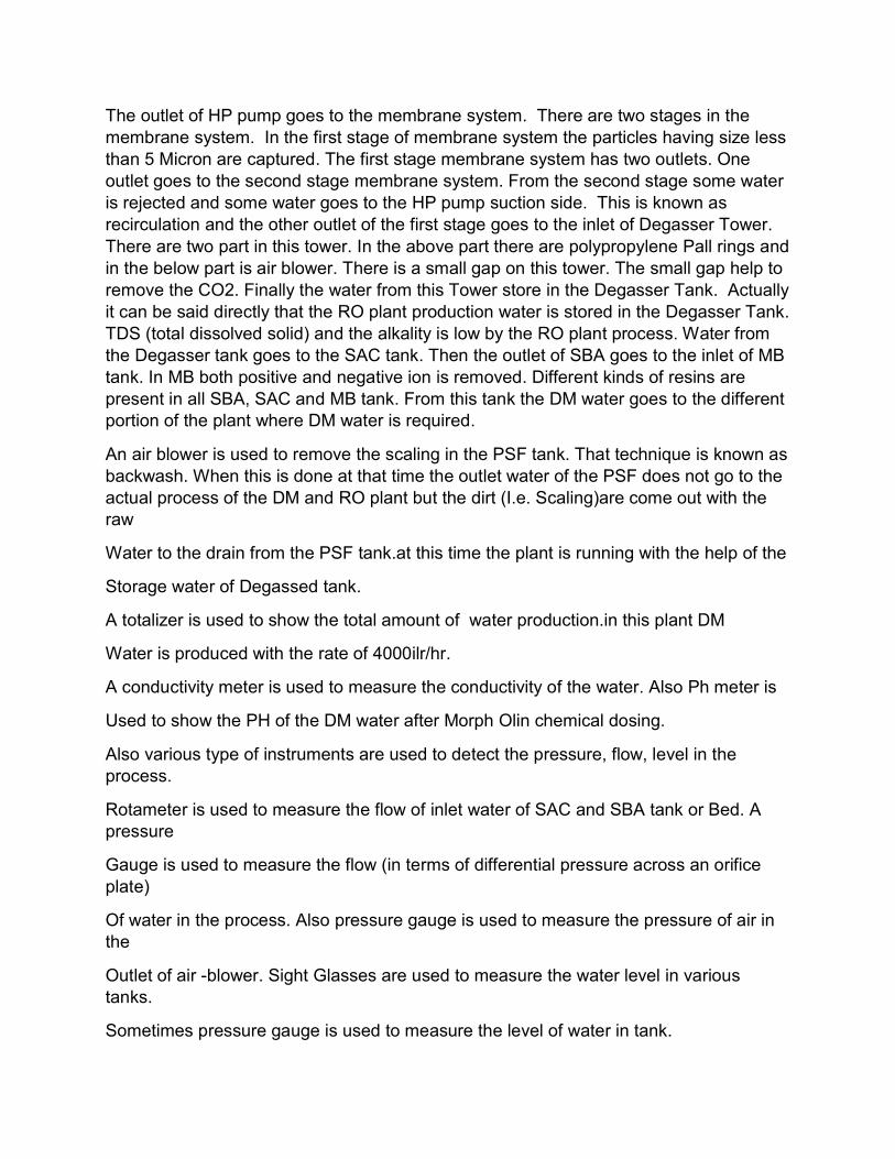
PH METER
A pH meter is an electronic device used for measuring the pH (acidity or alkalinity) of a Liquid(though special probes are sometimes used to measure the pH of semi-solid Substances).A typical pH meter consists of a special measuring probe(a glass electrode) connected to an electronic meter that measures and displays the pH reading.
Calibration & use
For very precise work the pH meter should be calibrated be for each measurement. For
Normal used calibrated should be performed at the beginning of each day for general
Purposes buffers at pH 4.01 and pH 10.00 are acceptable. A third control allows the temp to be set. Stander buffer sachets ,which can be obtained from a variety of suppliers,
Usually state how the buffer value changes with temp. For more precise measurements, a three buffer solution calibration is preferred.as pH 7 is essentially. A zero point calibration calibrating at pH7 fast closest to the point of interest second and checking the third point will provide a more linear accuracy to what is essentially a nonlinear problem. Some meters allow a three point calibration and that is the preferred scheme for the most accurate work. Higher quality metres will have a provision to account for temperature Coefficient correction and high end pH probe have temperature probes built in. The calibration process correlates the voltage produced by the probe with the pH scale. After each signal measurement, the probe is rinsed with distilled water or deionized water to remove any traces of the solution being measured, blotted with a scientific wipe to absorb any remaining water which could dilute the sample and thus alter the reading, and then quickly immersed in another solution.
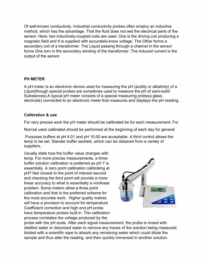
ROTAMETER
A Rotameter is a variable area type of flow metre that is used to widely used to measure the flow rate of a fluid in a plant. That rotameter is an industrial flow metre used to measure the flow rate of liquids and gases. The rotameter consists of a tube and float. The float response to flowrate changes is linear, and a 10-to-1 flow range or turndown is standard.
PRINCIPLE OF OPERATION
The rotameter’s operation is based on the variable area principle fluid flow raises float in a tapered tube, increasing the area for passage of the fluid. The greater the flow the higher the float is raised. The height of the float is directly proportional to the flowrate. With liquids, the float is raised by the combination of buoyancy of the liquid and the velocity head of the fluid. With gases, buoyancy is negligible, and the float responds to the velocity head alone.
The float moves up or down in the tube in proportion to the fluid flow rate and the annular area between the float and the tube wall. The float reaches a stable position in the tube When the upward force exerted by the flowing fluids equals the downward gravitational force exerted by the weight of the float .A change in flow rate upsets this balance of forces. The float then moves up or down, changing the annular area until it again reaches a position where the forces are in equilibrium. To satisfy the force equation, the perimeter floats assumes a distinct position for every constant flow rate. However, it is important to note that because the float position is gravity dependent, rotameters must be vertically oriented and mounted.

BOURDEN TUBE PRESSURE GAUGE
A Bourden gauge is a pressure indicator; it works with a "C" shaped tube oval in cross section that tries to straighten under pressure .when the tube tries to straighten it pulls on a connecting arm which turns a needle that is against a card that states the pressure .The device was invented by Eugene Bourden in the year 1849 .The basics idea behind the device is that, cross sectional tubing when deformed any way tend to regain its circular form under the action of pressure. The Bourden Pressure Gauges used today have a slight elliptical cross-section and the tube is generally bent in a “C” shape of arc length of about 27 degree. The detailed diagram of Bourden tube is shown below.
As seen in the figure, the pressure input is given to a socket which is soldered to the tube at the base. The other end or free end of the device is sealed by a tip. This tip is connected to a segmental lever through an adjustable length link. The lever length may also be adjustable. The segmental lever is suitably pivoted and the spindle holds the pointer as shown in the figure. A hair spring is sometimes used to fasten the spindle of the frame of the instrument to provide necessary for proper machining of the gear teeth and thereby freeing the system from the backlash. Any error due to friction in the spindle bearings is known as lost motion. The mechanical construction has to be highly accurate in the case of Bourden Tube Gauge. If we consider a cross-section of the tube, its outer edge will have a large surface than the inner portion. The tube walls have a thickness between 0.01 and 0.05 inches.
Parts of Bourden Gauge
An elastic transducer that is Bourden Tube which is fixed and open at one end to receive the pressure which is to be measured. The other end of the Bourden Tube is free and closed. The cross-section of the Bourden Tube is elliptical. The Bourden Tube is in a bent from to look like a circular arc. To the free end of the Bourden Tube is attached an adjustable link, which is in turn connected to a sector and pinion as shown in the diagram. To the shaft of the pinion is connected a pointer which sweeps over a pressure calibrated scale.
INSTRUMENTATION AT ECL, HALDIA
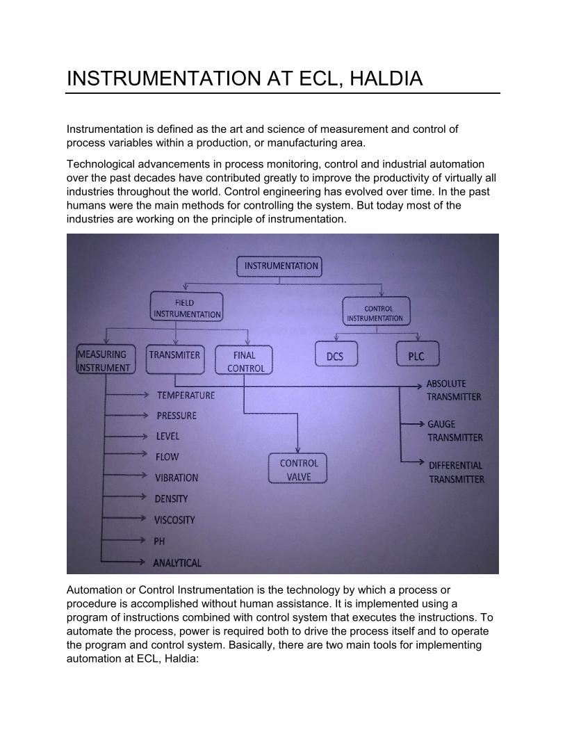
Instrumentation is defined as the art and science of measurement and control of process variables within a production, or manufacturing area.
Technological advancements in process monitoring, control and industrial automation over the past decades have contributed greatly to improve the productivity of virtually all industries throughout the world. Control engineering has evolved over time. In the past humans were the main methods for controlling the system. But today most of the industries are working on the principle of instrumentation.
Automation or Control Instrumentation is the technology by which a process or procedure is accomplished without human assistance. It is implemented using a program of instructions combined with control system that executes the instructions. To automate the process, power is required both to drive the process itself and to operate the program and control system. Basically, there are two main tools for implementing automation at ECL, Haldia:
1. PLCs with SCADA control. 2. PLCs and controllers with DCS control.
PLCs being remotely controlled with the SCADA based PC system are installed to acquire the control of conveyer belts and feeders. The conveyer belts and feeders are more often operated by a 3 Phase Induction Motor which is controlled by the PLCs and acquired SCADA systems. DCS control is used as more advanced tool of industrial automation and serves the plant portions that need a multi-tagging sort of structure. It basically serves instrumentations for different types of process parameters unlike PLCs that more often used for similar tagging. One more point of concern is that PLCs can time is much lesser than that of DCS as a result of which the section of plant that needs a quicker operation or trip are preferably controlled over PLCs.
Conclusion
During our visit to the ECL plant we saw a Number of industrial tools and equipment to help and support different process in sponge iron plant the system for a more often PLC based DCS operating system in the plant there was a Number of controllers and control equipment to fulfil the need of the plant in different aspects basically in SAP Da systems consisted of PC DLC test control of 3 phase induction motors that why are responsible for moving of the conveyor belts for Pal Rotary claim ID fan and FD fans at cetera this system control and there from the motor control Centre FDA and star delta starters for serving the operators Motors in the Coke oven plant the entire system was monitored on the AC Ada best PC systems and of course utilizing the process taking under PLC software being used for the ST Idea system was Win CC 7.2 and the PL CS being frequently used for a schematic S7 300 buy Siemens for the power plant control the plant used in DCS control mechanism that is in each and every part of the system there are controllers and transmitter for regular monitoring as well as control of the process the prescribed speed of turbine was 3000 RPM to achieve a generator 50 power signal. A major part of this generate power is exported to WBSEDCL read is 10 and only accessible portion of The generated power has been consumed in order to sub for the production of raw materials that is sponge Iron and coke for the production of ductile iron pipes and Fittings at Khardah it has been a great experience being training at CCL Haldia and the knowledge gained hair seems quite fruitful for us.
It has been a great experience being trainees at ECL, Haldia and the knowledge we gained here seems quite fruitful for us.
Might we be able to serve for humanity with what we have gained here ,
Trainee Students

Bibliography
Industrial Training at Electrosteel Castings Ltd. Haldia
Wikipedia
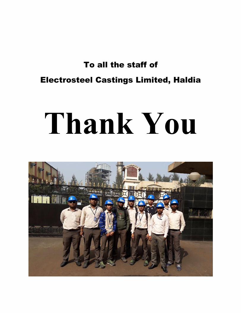
To all the staff of
Electrosteel Castings Limited, Haldia