Industrial Mufflers
12
NCS Acoustics Ltd | +64 9 269 0001 | [email protected] | www.ncsacoustics.co.nz | New Zealand Industrial Mufflers Absorptive, Reactive, Reactive Lined, Reactive Side Entry, Reactive Side Entry Lined V1 NCS Acoustics provide a range of Mufflers for industrial applications; Absorptive, Reactive and Lined Reactive. Call us and let our expert acoustic engineers provide you with suitable options. • Guaranteed to comply with specified performance. • Durable internal and exterior construction. • Designed and manufactured to individual requirements, based on a standard design. • Straight through or side entry. • Can be supplied with welded cradle or cleat mounts.
Transcript of Industrial Mufflers
NCS Acoustics Ltd | +64 9 269 0001 | [email protected] | www.ncsacoustics.co.nz | New Zealand
Industrial Mufflers Absorptive, Reactive, Reactive Lined, Reactive Side Entry, Reactive Side Entry Lined
V1
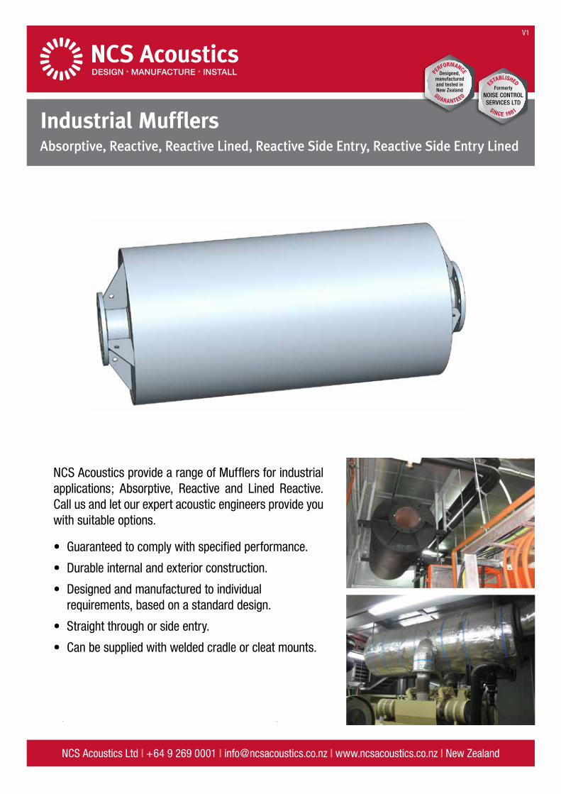
NCS Acoustics provide a range of Mufflers for industrial applications; Absorptive, Reactive and Lined Reactive. Call us and let our expert acoustic engineers provide you with suitable options.
• Guaranteed to comply with specified performance.
• Durable internal and exterior construction.
• Designed and manufactured to individual requirements, based on a standard design.
• Straight through or side entry.
• Can be supplied with welded cradle or cleat mounts.
2 | Mufflers
STATIC INSERTION LOSS (dB)
ModelTemp (C˚)
Frequency (Hz)
63 125 250 500 1k 2k 4k 8k
A-05020 10 18 34 50 50 50 50 46
500 5 13 24 40 50 50 50 48
A-08020 16 22 39 50 50 50 50 39
500 12 18 28 43 50 50 50 46
A-10020 16 25 40 50 50 50 47 31
500 10 19 31 44 50 50 49 41
A-12520 16 25 39 47 50 50 39 28
500 10 19 30 42 48 50 46 35
A-15020 16 24 34 42 50 44 31 25
500 11 19 28 37 45 48 39 29
A-20020 14 22 29 36 39 26 19 14
500 9 17 25 32 37 34 23 17
A-25020 14 26 45 45 42 25 16 13
500 7 19 33 45 44 36 22 15
A-30020 17 28 36 38 42 25 12 10
500 10 21 31 37 40 36 20 11
A-35020 20 34 40 42 50 31 13 11
500 11 25 36 41 45 43 24 12
A-40020 20 34 43 43 42 20 12 9
500 11 25 37 43 43 34 17 11
A-45020 20 34 43 39 39 15 10 8
500 11 25 37 41 39 30 13 9
A-50020 20 34 39 39 34 13 9 7
500 11 25 36 39 37 26 11 8
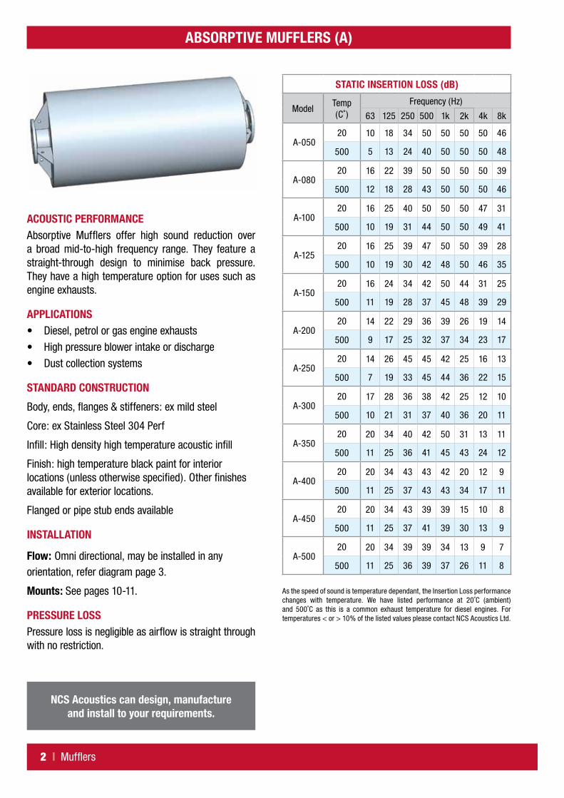
ABSORPTIVE MUFFLERS (A)
ACOUSTIC PERFORMANCEAbsorptive Mufflers offer high sound reduction over a broad mid-to-high frequency range. They feature a straight-through design to minimise back pressure. They have a high temperature option for uses such as engine exhausts.
APPLICATIONS• Diesel, petrol or gas engine exhausts
• High pressure blower intake or discharge
• Dust collection systems
STANDARD CONSTRUCTION
Body, ends, flanges & stiffeners: ex mild steel
Core: ex Stainless Steel 304 Perf
Infill: High density high temperature acoustic infill
Finish: high temperature black paint for interior locations (unless otherwise specified). Other finishes available for exterior locations.
Flanged or pipe stub ends available
INSTALLATION
Flow: Omni directional, may be installed in any orientation, refer diagram page 3.
Mounts: See pages 10-11.
PRESSURE LOSSPressure loss is negligible as airflow is straight through with no restriction.
NCS Acoustics can design, manufacture and install to your requirements.
As the speed of sound is temperature dependant, the Insertion Loss performance changes with temperature. We have listed performance at 20˚C (ambient) and 500˚C as this is a common exhaust temperature for diesel engines. For temperatures < or > 10% of the listed values please contact NCS Acoustics Ltd.

Mufflers | 3
DIMENSIONS & MASS
Model
Dimensions (mm)Mass (kg)Nominal
BoreBody
DiameterLength Over
Flanges
A-50 50 200 1050 27
A-80 80 320 1050 47
A-100 100 400 1400 80
A-125 125 500 1400 108
A-150 150 600 1400 142
A-200 200 700 1450 241
A-250 250 750 1500 275
A-300 300 900 1800 428
A-350 350 1050 2100 611
A-400 400 1200 2400 819
A-450 450 1350 2700 1074
A-500 500 1500 3000 1629
NOTES
ABSORPTIVE MUFFLERS (A)
Inlet & Exit Flanges
Length Over Flanges
Body
Dia
FL FL
Nom
Bore

4 | Mufflers
REACTIVE MUFFLERS (R)
STATIC INSERTION LOSS (dB)
ModelTemp (C˚)
Frequency (Hz)
63 125 250 500 1k 2k 4k 8k
R-05020 5 35 35 30 15 15 15 15
500 0 16 35 33 24 15 15 15
R-08020 6 35 35 30 10 15 15 15
500 0 17 35 33 22 12 15 15
R-10020 10 35 35 30 15 15 15 15
500 0 19 35 33 24 15 15 15
R-12520 15 35 35 30 15 15 15 15
500 3 23 35 33 24 15 15 15
R-15020 20 35 35 25 15 15 15 15
500 11 26 35 31 21 15 15 15
R-20020 20 30 30 20 15 15 15 15
500 14 24 30 26 18 15 15 15
R-25020 20 30 30 20 15 15 15 15
500 14 24 30 26 18 15 15 15
R-30020 25 30 30 20 15 15 15 15
500 22 27 30 26 18 15 15 15
R-35020 28 29 29 17 16 15 15 15
500 23 29 29 24 17 15 15 15
R-40020 31 28 28 15 16 15 15 15
500 26 31 28 23 16 16 15 15
ACOUSTIC PERFORMANCEReactive Mufflers use resonance to achieve high attenuation at low-to-mid frequencies. These mufflers are particularly suitable for applications such as food processes where porous infill materials are not permitted.
APPLICATIONS• Diesel, petrol or gas engine exhausts
• Compressor intake or discharge
• Blowers
• Multi-lobe intake or exhausts
• Vacuum pump discharge
STANDARD CONSTRUCTION
Body, Ends, Flanges & Stiffeners: ex Mild Steel.
Interior Pipework: ex Mild Steel.
Finish: high temperature black paint for interior locations (unless otherwise specified). Other finishes available for exterior locations.
Flanged or pipe stub ends available.
INSTALLATION
Flow: Direction as indicated, may be installed in any orientation, refer diagram page 5.
Mounts: See pages 10-11.
PRESSURE LOSSRefer graphs on page 9.
NCS Acoustics can design, manufacture and install to your requirements.
As the speed of sound is temperature dependant, the Insertion Loss performance changes with temperature. We have listed performance at 20˚C (ambient) and 500˚C as this is a common exhaust temperature for diesel engines. For temperatures < or > 10% of the listed values please contact NCS Acoustics Ltd.

Mufflers | 5
REACTIVE MUFFLERS (R)
Inlet & Exit Flanges
Length Over Flanges
Body
Dia
Nom
Bore
Flow
Manufacturing Tag is on the Inlet End
FL FL
DIMENSIONS & MASS
Model
Dimensions (mm)Mass (kg)Nominal
BoreBody
DiameterLength Over
Flanges
R-050 50 200 1150 33
R-080 80 320 1350 65
R-100 100 400 1550 92
R-125 125 500 1600 128
R-150 150 600 1700 173
R-200 200 700 1750 304
R-250 250 750 2100 405
R-300 300 900 2450 601
R-350 350 1050 2700 800
R-400 400 1200 3000 1017
NOTES

6 | Mufflers
REACTIVE LINED MUFFLERS (RL)
STATIC INSERTION LOSS (dB)
ModelTemp (C˚)
Frequency (Hz)
63 125 250 500 1k 2k 4k 8k
RL-08020 6 35 38 35 20 25 25 25
500 0 17 36 37 29 22 25 25
RL-10020 10 35 38 35 25 25 25 25
500 0 19 36 37 31 25 25 25
RL-12520 15 35 38 30 25 25 25 25
500 2 22 36 35 28 25 25 25
RL-15020 20 35 38 25 25 25 25 25
500 11 26 36 33 25 25 25 25
RL-20020 20 30 33 25 25 25 25 25
500 14 24 31 30 25 25 25 25
RL-25020 20 30 33 25 25 25 25 25
500 14 24 31 30 25 25 25 25
RL-30020 25 30 33 25 25 25 25 25
500 22 27 31 30 25 25 25 25
RL-350
RL-400
ACOUSTIC PERFORMANCEReactive Lined Mufflers are a combination of a reactive muffler and absorptive muffler in one package. These offer high sound reduction over a very broad frequency range.
APPLICATIONSSpecifically designed for blower inlets and outlets.
STANDARD CONSTRUCTION
Reactive Lined Mufflers are Reactive Mufflers with the addition of a high density high temperature acoustic infill.
Body, Ends, Flanges & Stiffeners: ex Mild Steel.
Interior Pipework: ex Mild Steel.
Infill: High density high temperature acoustic infill
Finish: high temperature black paint for interior locations (unless otherwise specified). Other finishes available for exterior locations.
Flanged or pipe stub ends available.
INSTALLATION
Flow: Direction as indicated, may be installed in any orientation, refer Reactive Muffler diagram page 5.
Mounts: See pages 10-11.
PRESSURE LOSSRefer graphs on page 9.
DIMENSIONS & MASS
Model
Dimensions (mm)Mass (kg)Nominal
BoreBody
DiameterLength Over
Flanges
RL-080 80 320 1350 84
RL-100 100 400 1550 117
RL-125 125 500 1600 162
RL-150 150 600 1700 219
RL-200 200 700 1750 358
RL-250 250 750 2100 471
RL-300 300 900 2450 696
RL-350 350 1050 2700 923
RL-400 400 1200 3000 1173
NCS Acoustics can design, manufacture and install to your requirements.
As the speed of sound is temperature dependant, the Insertion Loss performance changes with temperature. We have listed performance at 20˚C (ambient) and 500˚C as this is a common exhaust temperature for diesel engines. For temperatures < or > 10% of the listed values please contact NCS Acoustics Ltd.
Mufflers in this size range are specially designed. For initial design purposes use acoustic performance
figures for R300L and contact NCS Acoustics.
Inlet & Exit Flanges
Length Over Flanges
Body
Dia
Nom
Bore
Flow
Manufacturing Tag is on the Inlet End
FL FL
Refer drawings on page 5.
Mufflers | 7
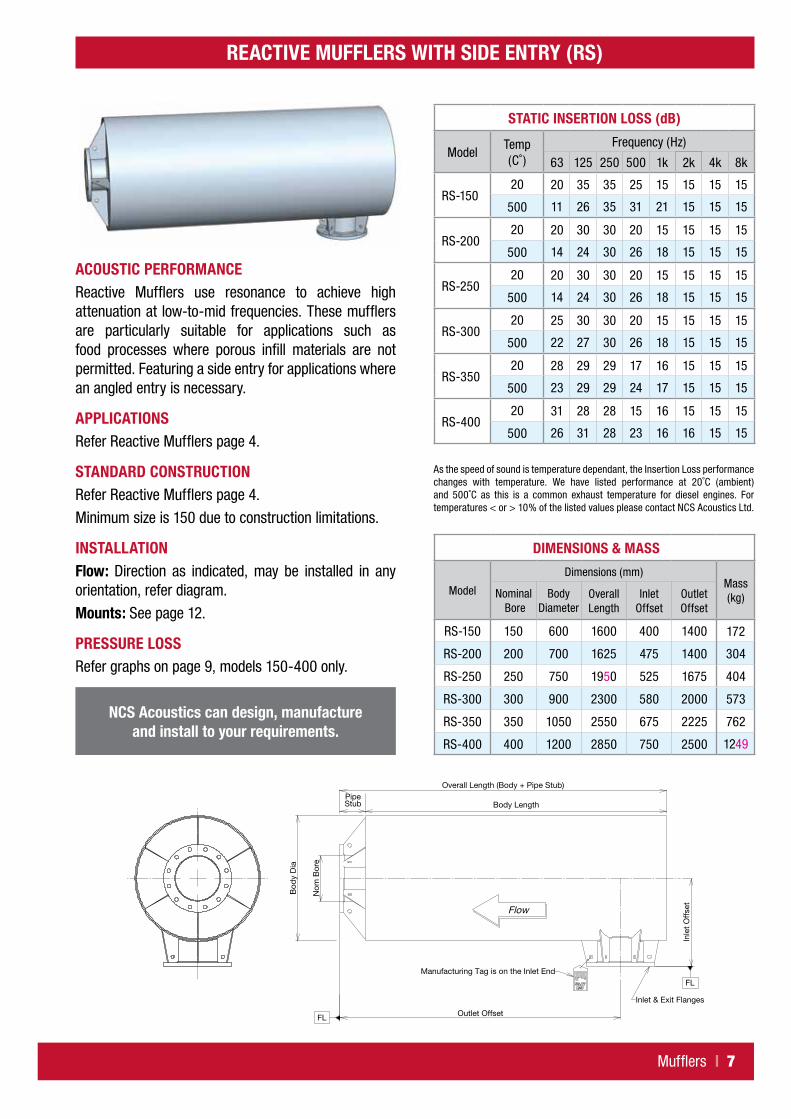
REACTIVE MUFFLERS WITH SIDE ENTRY (RS)
Bod
y D
ia
Nom
Bor
e
Outlet Offset
PipeStub
Inle
t O
ffse
t
Flow
Manufacturing Tag is on the Inlet End
Inlet & Exit Flanges
FL
FL
Overall Length (Body + Pipe Stub)
Body Length
STATIC INSERTION LOSS (dB)
ModelTemp (C˚)
Frequency (Hz)
63 125 250 500 1k 2k 4k 8k
RS-15020 20 35 35 25 15 15 15 15
500 11 26 35 31 21 15 15 15
RS-20020 20 30 30 20 15 15 15 15
500 14 24 30 26 18 15 15 15
RS-25020 20 30 30 20 15 15 15 15
500 14 24 30 26 18 15 15 15
RS-30020 25 30 30 20 15 15 15 15
500 22 27 30 26 18 15 15 15
RS-35020 28 29 29 17 16 15 15 15
500 23 29 29 24 17 15 15 15
RS-40020 31 28 28 15 16 15 15 15
500 26 31 28 23 16 16 15 15
DIMENSIONS & MASS
Model
Dimensions (mm)Mass (kg)Nominal
BoreBody
DiameterOverall Length
Inlet Offset
Outlet Offset
RS-150 150 600 1600 400 1400 172
RS-200 200 700 1625 475 1400 304
RS-250 250 750 1950 525 1675 404
RS-300 300 900 2300 580 2000 573
RS-350 350 1050 2550 675 2225 762
RS-400 400 1200 2850 750 2500 1249
ACOUSTIC PERFORMANCEReactive Mufflers use resonance to achieve high attenuation at low-to-mid frequencies. These mufflers are particularly suitable for applications such as food processes where porous infill materials are not permitted. Featuring a side entry for applications where an angled entry is necessary.
APPLICATIONSRefer Reactive Mufflers page 4.
STANDARD CONSTRUCTIONRefer Reactive Mufflers page 4.
Minimum size is 150 due to construction limitations.
INSTALLATIONFlow: Direction as indicated, may be installed in any orientation, refer diagram.
Mounts: See page 12.
PRESSURE LOSSRefer graphs on page 9, models 150-400 only.
NCS Acoustics can design, manufacture and install to your requirements.
As the speed of sound is temperature dependant, the Insertion Loss performance changes with temperature. We have listed performance at 20˚C (ambient) and 500˚C as this is a common exhaust temperature for diesel engines. For temperatures < or > 10% of the listed values please contact NCS Acoustics Ltd.
8 | Mufflers
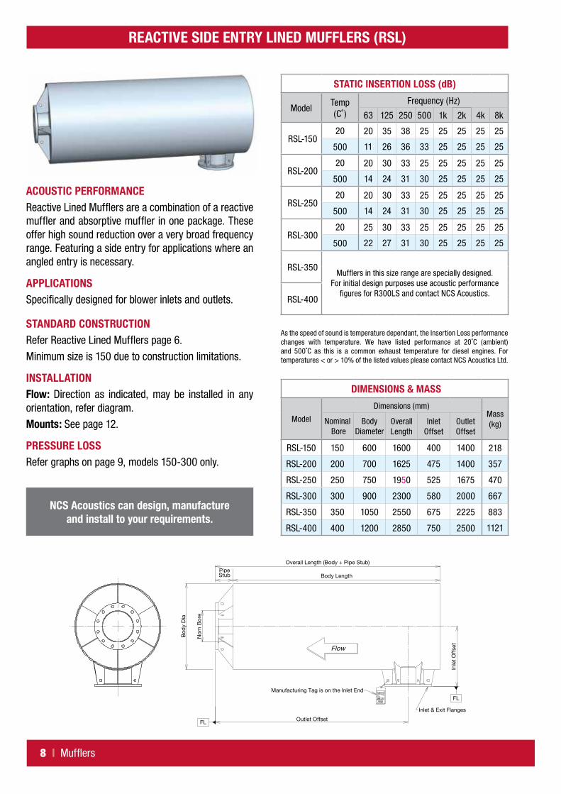
REACTIVE SIDE ENTRY LINED MUFFLERS (RSL)
Bod
y D
ia
Nom
Bor
e
Outlet Offset
PipeStub
Inle
t O
ffse
t
Flow
Manufacturing Tag is on the Inlet End
Inlet & Exit Flanges
FL
FL
Overall Length (Body + Pipe Stub)
Body Length
DIMENSIONS & MASS
Model
Dimensions (mm)Mass (kg)Nominal
BoreBody
DiameterOverall Length
Inlet Offset
Outlet Offset
RSL-150 150 600 1600 400 1400 218
RSL-200 200 700 1625 475 1400 357
RSL-250 250 750 1950 525 1675 470
RSL-300 300 900 2300 580 2000 667
RSL-350 350 1050 2550 675 2225 883
RSL-400 400 1200 2850 750 2500 1121
ACOUSTIC PERFORMANCEReactive Lined Mufflers are a combination of a reactive muffler and absorptive muffler in one package. These offer high sound reduction over a very broad frequency range. Featuring a side entry for applications where an angled entry is necessary.
APPLICATIONSSpecifically designed for blower inlets and outlets.
STANDARD CONSTRUCTIONRefer Reactive Lined Mufflers page 6.
Minimum size is 150 due to construction limitations.
INSTALLATIONFlow: Direction as indicated, may be installed in any orientation, refer diagram.
Mounts: See page 12.
PRESSURE LOSSRefer graphs on page 9, models 150-300 only.
STATIC INSERTION LOSS (dB)
ModelTemp (C˚)
Frequency (Hz)
63 125 250 500 1k 2k 4k 8k
RSL-15020 20 35 38 25 25 25 25 25
500 11 26 36 33 25 25 25 25
RSL-20020 20 30 33 25 25 25 25 25
500 14 24 31 30 25 25 25 25
RSL-25020 20 30 33 25 25 25 25 25
500 14 24 31 30 25 25 25 25
RSL-30020 25 30 33 25 25 25 25 25
500 22 27 31 30 25 25 25 25
RSL-350
RSL-400
NCS Acoustics can design, manufacture and install to your requirements.
As the speed of sound is temperature dependant, the Insertion Loss performance changes with temperature. We have listed performance at 20˚C (ambient) and 500˚C as this is a common exhaust temperature for diesel engines. For temperatures < or > 10% of the listed values please contact NCS Acoustics Ltd.
Mufflers in this size range are specially designed. For initial design purposes use acoustic performance
figures for R300LS and contact NCS Acoustics.
Mufflers | 9
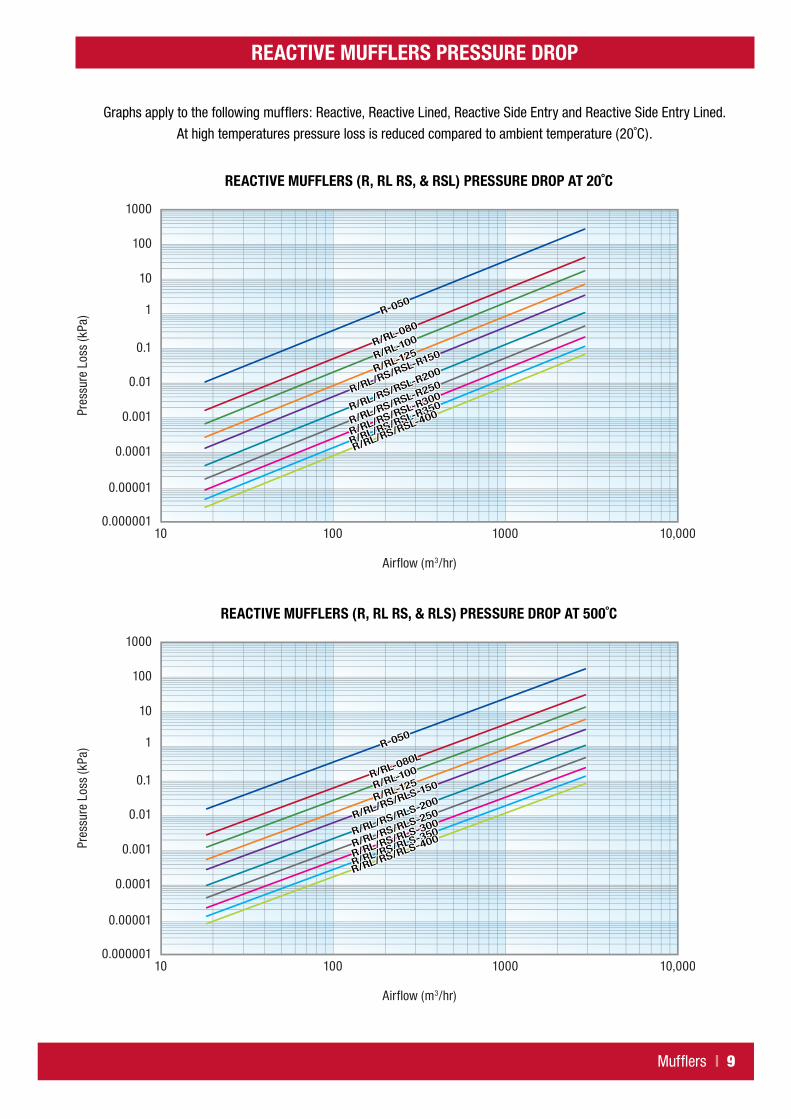
REACTIVE MUFFLERS PRESSURE DROP
Graphs apply to the following mufflers: Reactive, Reactive Lined, Reactive Side Entry and Reactive Side Entry Lined.
At high temperatures pressure loss is reduced compared to ambient temperature (20˚C).
R-050R-050R-050
R/RL-080
R/RL-080
R/RL-080
R/RL-100
R/RL-100
R/RL-100
R/RL-125
R/RL-125
R/RL-125
R/RL/RS/RSL-R150
R/RL/RS/RSL-R150
R/RL/RS/RSL-R150
R/RL/RS/RSL-R200
R/RL/RS/RSL-R200
R/RL/RS/RSL-R200
R/RL/RS/RSL-R250
R/RL/RS/RSL-R250
R/RL/RS/RSL-R250
R/RL/RS/RSL-R300
R/RL/RS/RSL-R300
R/RL/RS/RSL-R300
R/RL/RS/RSL-R350
R/RL/RS/RSL-R350
R/RL/RS/RSL-R350
R/RL/RS/RSL-400
R/RL/RS/RSL-400
R/RL/RS/RSL-400Pr
essu
re L
oss
(kPa
)
Airflow (m3/hr)
0.000001
0.00001
0.0001
0.001
0.01
0.1
1
10
100
1000
10 100 1000 10,000
REACTIVE MUFFLERS (R, RL RS, & RSL) PRESSURE DROP AT 20˚C
R-050R-050R-050
R/RL-080L
R/RL-080L
R/RL-080L
R/RL-100R/RL-100R/RL-100
R/RL-125R/RL-125R/RL-125
R/RL/RS/RLS-150
R/RL/RS/RLS-150
R/RL/RS/RLS-150
R/RL/RS/RLS-200
R/RL/RS/RLS-200
R/RL/RS/RLS-200
R/RL/RS/RLS-250
R/RL/RS/RLS-250
R/RL/RS/RLS-250
R/RL/RS/RLS-300
R/RL/RS/RLS-300
R/RL/RS/RLS-300
R/RL/RS/RLS-350
R/RL/RS/RLS-350
R/RL/RS/RLS-350
R/RL/RS/RLS-400
R/RL/RS/RLS-400
R/RL/RS/RLS-400Pres
sure
Los
s (k
Pa)
Airflow (m3/hr)
0.000001
0.00001
0.0001
0.001
0.01
0.1
1
10
100
1000
10 100 1000 10,000
REACTIVE MUFFLERS (R, RL RS, & RLS) PRESSURE DROP AT 500˚C

10 | Mufflers
FLANGES
STRAIGHT THROUGH MUFFLERS MOUNT INFORMATION
• Mounts are optional.
• Suitable for straight through or side entry design or can be custom made to specifications.
• Mounts are welded to muffler body.
• Finish is black high temperature paint unless otherwise specified.
STRAIGHT THROUGH CRADLE MOUNT
For base supported mufflers.
STRAIGHT THROUGH CLEAT MOUNT
For suspended mufflers.
Body Length
Bod
y D
ia
L1
W1
M1
50 Typ
=75= =75=
T
H
Body Length
Bod
y D
ia
L2
W2
M2
100
Typ
75 T
yp
=75==75=
Ex 100 x 50PFC
Body Length
Bod
y D
ia
L1
W1
M1
50 Typ
=75= =75=
T
H
Body Length
Bod
y D
ia
L2
W2
M2
100
Typ
75 T
yp
=75==75=
Ex 100 x 50PFC
BS10, Table E unless specified by client.
Inlet & Exit Flanges
TH
PCD
Nom Bore (mm)
Dimensions (mm) No. of HolesBody Dia TH PCD Bolt Hole
Dia
050 152 10 114 18 4
080 184 11 146 18 4
100 216 13 178 18 8
125 254 14 210 18 8
150 279 17 235 22 8
200 337 19 292 22 8
250 406 20 356 22 12
300 457 20 406 25 12
350 527 20 470 25 12
400 578 20 521 25 12
450 641 20* 584 25 16
500 704 20 641 25 16

Mufflers | 11
STRAIGHT THROUGH MUFFLERS MOUNT INFORMATION (A, R & RL)
STRAIGHT THROUGH MUFFLERS AND MOUNTS DIMENSIONS & MASS (REFER DRAWINGS ON PAGE 10)
MUFFLER BODY MUFFLER ON CRADLE MUFFLER WITH CLEATS
ModelDimensions (mm)
Mass (kg)
Dimensions (mm)Mass (kg)
Dimensions (mm)Mass (kg)Body
DiaBody
Length T H M1 for Fixing Size L1 W1 M2 for
Fixing Size L2 W2
ABSO
RPTI
VE (A
)
A-050 200 900 27 100 200 14 for M12 750 150 29 14 for M12 750 350 30
A-080 320 900 47 100 260 14 for M12 750 270 52 14 for M12 750 470 51
A-100 400 1200 80 100 300 14 for M12 1050 350 85 14 for M12 1050 550 83
A-125 500 1200 108 100 350 14 for M12 1050 450 115 14 for M12 1050 650 111
A-150 600 1200 142 150 450 14 for M12 1050 550 153 14 for M12 1050 750 145
A-200 700 1200 241 150 500 14 for M12 1050 650 254 14 for M12 1050 850 244
A-250 750 1200 275 150 525 18 for M16 1050 700 289 18 for M16 1050 900 278
A-300 900 1500 428 150 600 18 for M16 1350 850 446 18 for M16 1350 1050 431
A-350 1050 1800 612 200 725 18 for M16 1650 1000 636 18 for M16 1650 1200 615
A-400 1200 2100 819 200 800 18 for M16 1950 1150 849 18 for M16 1950 1350 822
A-450 1350 2400 1074 200 875 18 for M16 2250 1300 1108 18 for M16 2250 1500 1077
A-500 1500 2700 1629 200 950 18 for M16 2550 1450 1662 18 for M16 2550 1650 1632
REAC
TIVE
(R
)
R-050 200 1000 33 100 200 14 for M12 850 150 35 14 for M12 850 350 36
R-080 320 1200 65 100 260 14 for M12 1050 270 69 14 for M12 1050 470 68
R-100 400 1350 92 100 300 14 for M12 1200 350 97 14 for M12 1200 550 95
R-125 500 1400 128 100 350 14 for M12 1250 450 135 14 for M12 1250 650 131
R-150 600 1500 173 150 450 14 for M12 1350 550 184 14 for M12 1350 750 177
R-200 700 1500 304 150 500 14 for M12 1350 650 318 14 for M12 1350 850 308
R-250 750 1800 405 150 525 18 for M16 1650 700 421 18 for M16 1650 900 408
R-300 900 2150 601 150 600 18 for M16 2000 850 619 18 for M16 2000 1050 605
R-350 1050 2400 800 200 725 18 for M16 2250 1000 825 18 for M16 2250 1200 803
R-400 1200 2700 1017 200 800 18 for M16 2550 1150 1047 18 for M16 2550 1350 1020
REAC
TIVE
LIN
ED (
RL)
RL-080 320 1200 84 100 260 14 for M12 1050 270 88 14 for M12 1050 470 87
RL-100 400 1350 117 100 300 14 for M12 1200 350 122 14 for M12 1200 550 120
RL-125 500 1400 162 100 350 14 for M12 1250 450 170 14 for M12 1250 650 166
RL-150 600 1500 219 150 450 14 for M12 1350 550 230 14 for M12 1350 750 222
RL-200 700 1500 358 150 500 14 for M12 1350 650 372 14 for M12 1350 850 362
RL-250 750 1800 471 150 525 18 for M16 1650 700 468 18 for M16 1650 900 475
RL-300 900 2150 696 150 600 18 for M16 2000 850 714 18 for M16 2000 1050 699
RL-350 1050 2400 923 200 725 18 for M16 2250 1000 948 18 for M16 2250 1200 926
RL-400 1200 2700 1173 200 800 18 for M16 2550 1150 1203 18 for M16 2550 1350 1176
ADDITIONAL INFORMATION
Visit our website or contact us for information on installation, testing, monitoring, maintenance services and technical guides.
Got a question? Call us to discuss with an experienced engineer: +64 9 269 0001
Or visit our website for more information:
www.ncsacoustics.co.nzData correct at time of publication, please ensure you have the latest version by checking our website. NCS Acoustics Limited accepts no liability for use of data within this brochure. Materials may be updated at any time without notice.
12 | Mufflers
Bod
y D
ia
Body Length
50 Typ Foot
W1
L1
=10 Ref= =10 Ref=
M1
Offset 1
Bod
y D
ia
Body Length
Offset 2
L2
W2
=75 Ref==75 Ref=
M2
100
Typ
75 T
yp
Cleats Ex 100 x 50 PFC
HT
Cradle Mounted Cleat MountsB
ody
Dia
Body Length
50 Typ Foot
W1
L1
=10 Ref= =10 Ref=
M1
Offset 1
Bod
y D
ia
Body Length
Offset 2
L2
W2
=75 Ref==75 Ref=
M2
100
Typ
75 T
yp
Cleats Ex 100 x 50 PFC
HT
Cradle Mounted Cleat Mounts
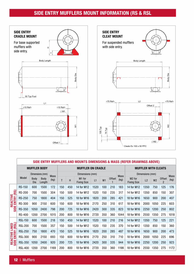
SIDE ENTRY MUFFLERS MOUNT INFORMATION (RS & RSL
SIDE ENTRY CRADLE MOUNT
For base supported mufflers with side entry.
SIDE ENTRY CLEAT MOUNT
For suspended mufflers with side entry.
Bod
y D
ia
Body Length
50 Typ Foot
W1
L1
=10 Ref= =10 Ref=
M1
Offset 1
Bod
y D
ia
Body Length
Offset 2
L2
W2
=75 Ref==75 Ref=
M2
100
Typ
75 T
yp
Cleats Ex 100 x 50 PFC
HT
Cradle Mounted Cleat Mounts
Bod
y D
iaBody Length
50 Typ Foot
W1
L1
=10 Ref= =10 Ref=
M1
Offset 1
Bod
y D
ia
Body Length
Offset 2
L2
W2
=75 Ref==75 Ref=
M2
100
Typ
75 T
yp
Cleats Ex 100 x 50 PFC
HT
Cradle Mounted Cleat Mounts
SIDE ENTRY MUFFLERS AND MOUNTS DIMENSIONS & MASS (REFER DRAWINGS ABOVE)
MUFFLER BODY MUFFLER ON CRADLE MUFFLER WITH CLEATS
ModelDimensions (mm)
Mass (kg)
Dimensions (mm)Mass (kg)
Dimensions (mm)Mass (kg)Body
DiaBody
LengthT H
M1 for Fixing Size
L1 W1Offset
1M2 for
Fixing SizeL2 W2
Offset 2
REAC
TIVE
SI
DE E
NTR
Y (R
S)
RS-150 600 1500 172 150 450 14 for M12 1520 100 210 183 14 for M12 1350 750 125 176
RS-200 700 1500 304 150 500 14 for M12 1520 150 235 317 14 for M12 1350 850 150 307
RS-250 750 1800 404 150 525 18 for M16 1820 200 285 421 18 for M16 1650 900 200 407
RS-300 900 2150 600 150 600 18 for M16 2170 250 310 617 18 for M16 2000 1050 225 603
RS-350 1050 2400 798 200 725 18 for M16 2420 300 335 823 18 for M16 2250 1200 250 802
RS-400 1200 2700 1015 200 800 18 for M16 2720 350 360 1044 18 for M16 2550 1350 275 1018
REAC
TIVE
LIN
ED
SIDE
EN
TRY
(RSL
) RSL-150 600 1500 218 150 450 14 for M12 1520 100 210 216 14 for M12 1350 750 125 221
RSL-200 700 1500 357 150 500 14 for M12 1520 150 235 370 14 for M12 1350 850 150 360
RSL-250 750 1800 470 150 525 18 for M16 1820 200 285 487 18 for M16 1650 900 200 473
RSL-300 900 2150 693 150 600 18 for M16 2170 250 310 710 18 for M16 2000 1050 225 696
RSL-350 1050 2400 920 200 725 18 for M16 2420 300 335 944 18 for M16 2250 1200 250 923
RSL-400 1200 2700 1169 200 800 18 for M16 2720 350 360 1198 18 for M16 2550 1350 275 1172