Industrial Injections Compound Turbo Installation For 6.7L
48
Industrial Injections Compound Turbo Installation For 6.7L Scorpion
Transcript of Industrial Injections Compound Turbo Installation For 6.7L

Industrial Injections Compound Turbo Installation
For 6.7L Scorpion
Pg. 2
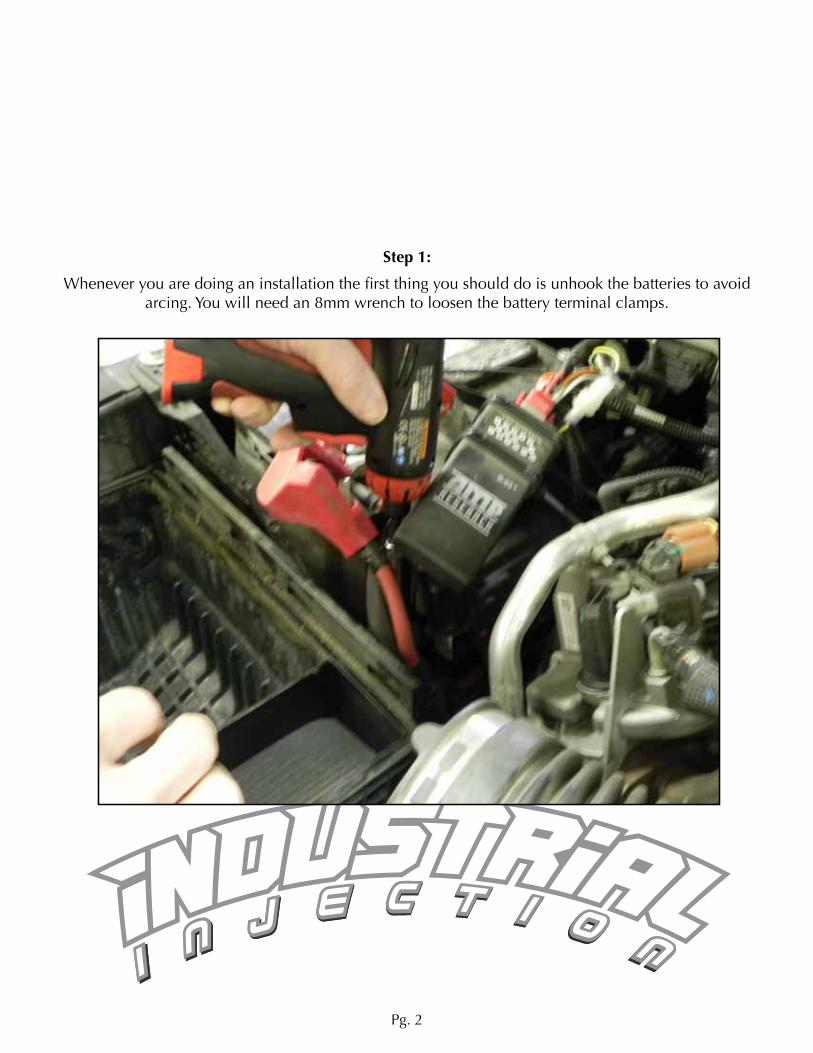
Step 1:
Whenever you are doing an installation the first thing you should do is unhook the batteries to avoid arcing. You will need an 8mm wrench to loosen the battery terminal clamps.
Pg. 3
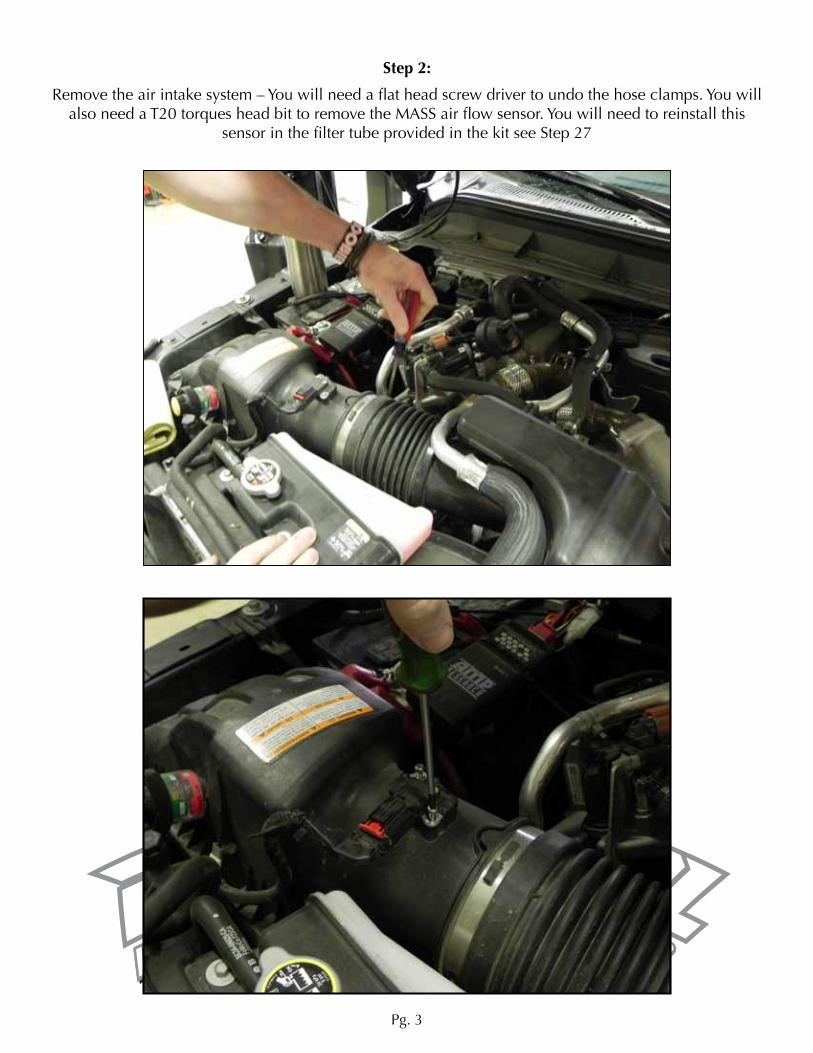
Step 2:
Remove the air intake system – You will need a flat head screw driver to undo the hose clamps. You will also need a T20 torques head bit to remove the MASS air flow sensor. You will need to reinstall this
sensor in the filter tube provided in the kit see Step 27

Pg. 4
Step 3:
Remove the factory air box using an 8mm socket, the bolt is located underneath the passenger’s side positive battery cable.
Step 4:
Remove the factory intake resonator box, there is one 8mm bolt holding this on.

Pg. 5
Step 5:
Remove the coolant lines from the EGR cooler & overflow tank. You will need a set of needle nosed pliers or vise grips.

Pg. 6
NOTE* You will need to remove the intake air box bracket using a 13mm socket in order to access the lower end of the coolant line running from the EGR cooler to
the radiator. You will also have to drain the coolant out of the radia-tor using your needle nose pliers
to turn the drain valve.

Pg. 7
Step 6:
Remove the factory boost sensor located in the upper intake manifold using a 7mm socket.Then using an 8mm socket remove the plastic upper intake manifold.

Pg. 8
Step 7:
Remove the factory up pipes running into the EGR cooler, use an 8mm socket for these bolts as well.

Pg. 9
Step 8:
Removing the Intake Manifold *
Whenever you are removing an intake manifold make sure you have shop rags handy to plug the ex-posed holes leading into the intake runners, this will avoid any lose nuts and bolts from being dropped
into the engine *
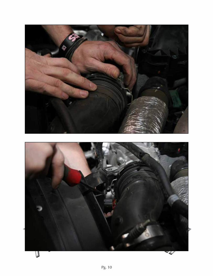
Remove the intake manifold using your 8mm wrench, you will need a flat head screw driver to pry up the wire keeper attaching the inter-cooler pipe to the intake manifold.
Pg. 10
Pg. 11
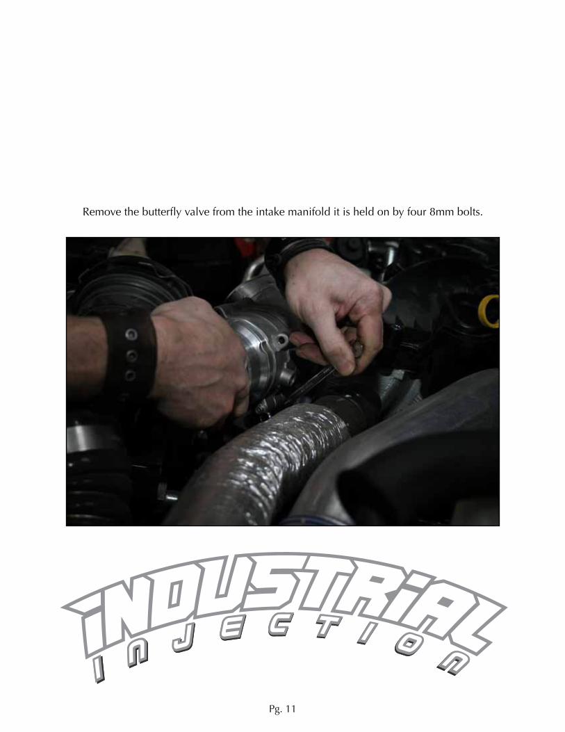
Remove the butterfly valve from the intake manifold it is held on by four 8mm bolts.

Pg. 12
Remove the crank case vent tube from the intake manifold by spinning the gray locking collar clockwise, then pull.

Pg. 13
Step 9:
EGR Cooler removal
There are seven 8mm bolts holding the EGR Cooler to the top of the passenger’s side intake manifold. There are 3 down each side and one in the center towards the front of the EGR Cooler.
Remove the 8mm nut holding the EGT probe sensor to the back of the EGR Cooler.

Pg. 14
Pg. 15
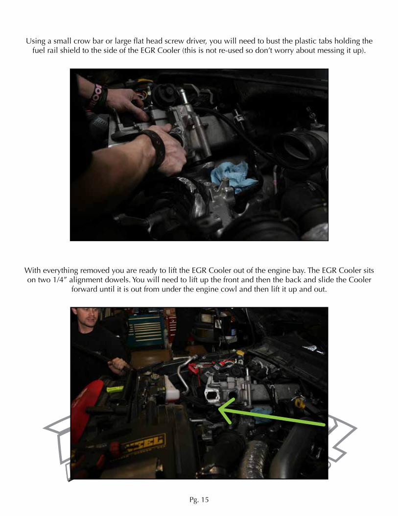
Using a small crow bar or large flat head screw driver, you will need to bust the plastic tabs holding the fuel rail shield to the side of the EGR Cooler (this is not re-used so don’t worry about messing it up).
With everything removed you are ready to lift the EGR Cooler out of the engine bay. The EGR Cooler sits on two 1/4” alignment dowels. You will need to lift up the front and then the back and slide the Cooler
forward until it is out from under the engine cowl and then lift it up and out.

Pg. 16

Pg. 17
Step 10:
Remove the factory up pipe using a 7/16” ratcheting wrench to loosen the V-Band clamp. Then there are three 13mm nuts holding the flange to the exhaust manifold.

Pg. 18
Step 11:
Once the up pipe is removed you will be able to see/feel the V-Band clamp connecting the factory down-pipe to the back of the factory turbo. Take the nut all the way off so you can spread the clamp far enough to slide it over the flange. These clamps are under extreme heat and are usually baked on, use
either a small pry bar or flat head screw driver to pry it off.
Underneath the truck you will need a 16mm and 17mm ratcheting wrench to undo the bolts connecting the down-pipe flange to the exhaust system.
The factory down-pipe is a two piece pipe, to remove the lower half of the down-pipe you will need a 15mm deep socket and ratchet to remove the large band clamp holding the two halves of the down-pipe together.
Now you can completely remove the factory down-pipe from the truck.

Pg. 19
Step 12:
With the EGR Cooler removed you can now install the provided EGR Blocker plates. There are three bolts that hold the large blocker plate down, leave the lower bolt out for now. It will be installed later to
hold down the provided heat shield.

Pg. 20
Install the factory EGT Probe into the small EGR blocker plate using a 14mm wrench.

Pg. 21
Step 13:
Install the aftermarket up-pipe provided in the kit using the factory 13mm nuts that where used to hold the factory up-pipe to the exhaust manifold.
Connect the factory EGT sensor to the aftermarket up-pipe using a 16mm wrench.
Using a 7/16 wrench or deep socket you can re-install and tighten the V-Band clamp to the upper end of the up-pipe
Step 14:
With the up-pipe in, install the provided head shield. You will see a reflective sheet of heat shield prod-uct in the kit, it has a sticky back and will be used to line the upper side of the metal heat shield. Com-
plete this before putting the heat shield into the engine bay. Use a razor knife to trim accordingly.

Pg. 22
Drop the heat shield into the engine bay on top of the factory intake manifold on the passenger’s side. One bolt will go through the lower side towards the front and into the large EGR Blocker plate. The other
bolt goes through the tab at the back of the shield towards the top by the small EGR Blocker plate.
Note: This nut needs to be installed after the heat shield is in place. If you installed the nut before hand the shield will not sit flat.

Pg. 23
Pg. 24
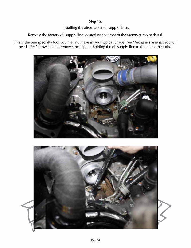
Step 15:
Installing the aftermarket oil supply lines.
Remove the factory oil supply line located on the front of the factory turbo pedestal.
This is the one specialty tool you may not have in your typical Shade Tree Mechanics arsenal. You will need a 3/4” crows foot to remove the slip nut holding the oil supply line to the top of the turbo.
Pg. 25
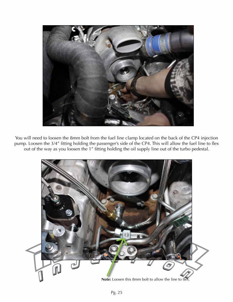
You will need to loosen the 8mm bolt from the fuel line clamp located on the back of the CP4 injection pump. Loosen the 3/4” fitting holding the passenger’s side of the CP4. This will allow the fuel line to flex
out of the way as you loosen the 1” fitting holding the oil supply line out of the turbo pedestal.
Note: Loosen this 8mm bolt to allow the line to flex.

Pg. 26
With the factory oil supply line removed you are ready to install the provided JIC fitting into the turbo pedestal. Then connect the T fitting to the JIC Fitting. There is one 90 degree fitting that will attach to one
side of the T fitting facing towards the driver’s side of the engine facing downwards, attach one of the stainless braided lines to the 90 degree fitting a route it upwards to the stock turbo.

Pg. 27
Pg. 28
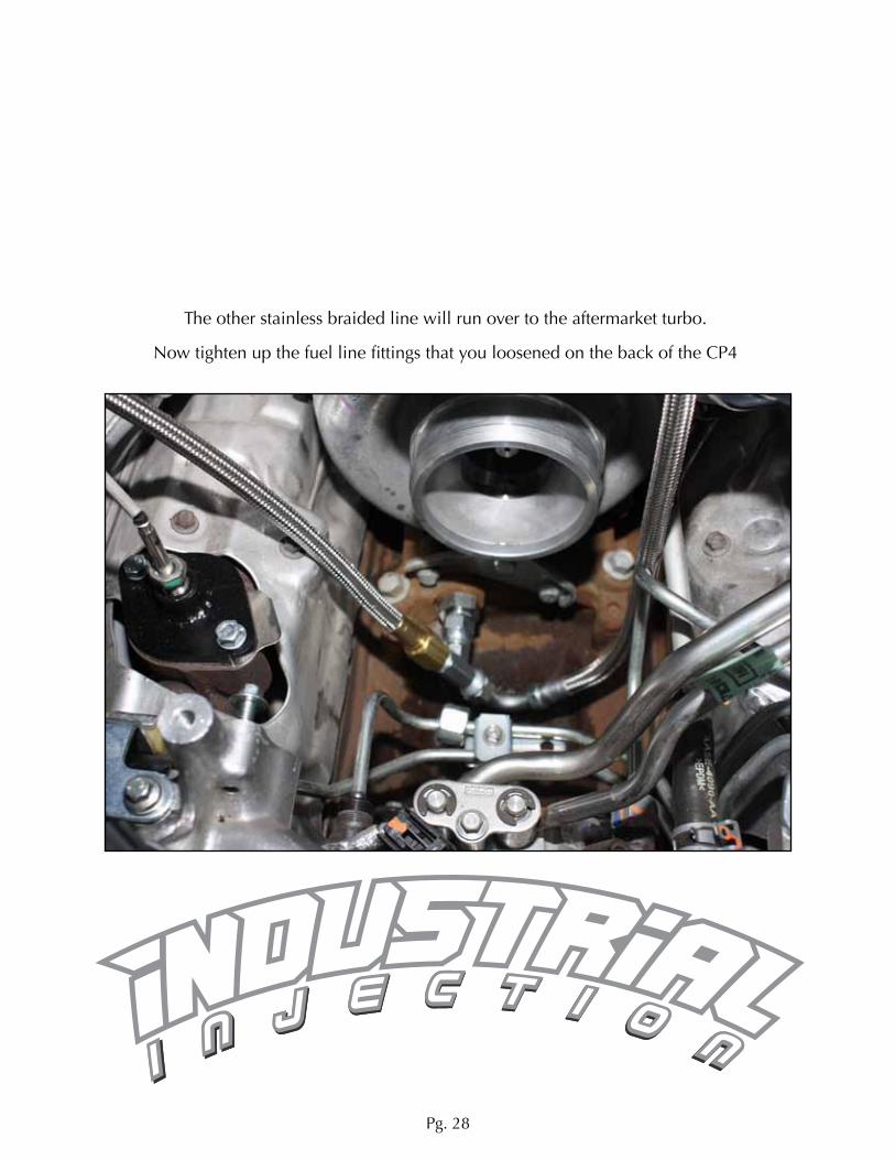
The other stainless braided line will run over to the aftermarket turbo.
Now tighten up the fuel line fittings that you loosened on the back of the CP4

Pg. 29
Step 16:
Install the provided intake air tube that connects to the doubled compressor housing of the factory turbo. Use hair spray to coat the inside of the provided rubber boots, this will make them temporarily slip-
pery to slide them all the way onto the aftermarket pipe. You have to do this to get the pipe lowered into place, once it is in you can then slide the boots onto the compressor housing. Tighten the clamps and the hair spray will become extremely sticky which will help avoid the boots from ever being blown off
under pressure.

Pg. 30
Step 17:
Install the aftermarket Y-Bridge.

Pg. 31
You will use the orange O-ring gaskets in the bottom of the factory Upper Intake manifold. There are little tabs that you will need to cut off for the O-rings to fit into the aftermarket Y-bridge.
Drop the Y-bridge into place and thread in the four bolts on the driver’s side flange first. Only thread them in about 2 or 3 threads.
Then move to the passenger’s side and thread those bolts in a couple of threads. If you are having trou-ble getting a bolt to thread in you will be able to lift the pipe up and down since the driver’s side bolts
where left loose.

Pg. 33
Step 18:
Installing the Turbo support bracket.
Before you install the bracket on the truck you need to install the oil return line fitting and hose. Once the bracket is permanently installed on the truck it will be very hard to install the fitting and hose.

Pg. 34
Now you will need to remove the inner fender liner in order to do this installation.
Once the fender liner is removed you will see two empty bolt holes near the front of the cylinder head. These two holes will accept the two 13mm bolts provided in the kit for the turbo bracket. Lower the
turbo bracket into place from the top, the upper section will slide into the notch in the heat shield previ-ously installed.
Pg. 35
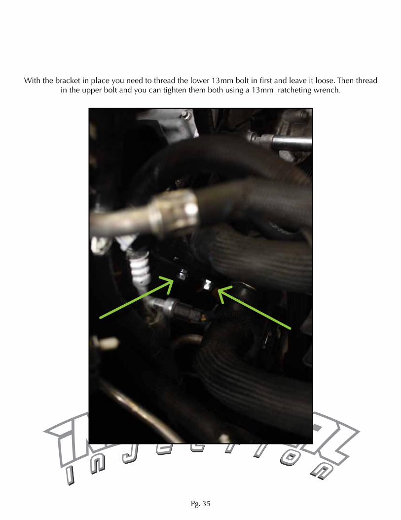
With the bracket in place you need to thread the lower 13mm bolt in first and leave it loose. Then thread in the upper bolt and you can tighten them both using a 13mm ratcheting wrench.

Pg. 36
NOTE: Check the top side of the bracket where the oil drain gasket goes between the bracket and the center cartridge of the turbo. This surface needs to be perfectly flat. If you see bubbling in the powder
coat finish, then you need to flatten the surface with a file or sander until it is perfectly smooth. If you do not get this surface flat it WILL LEAK.
Note: Notice the bubbleing in the powder coat. This will not seal.

Pg. 37
Pg. 38
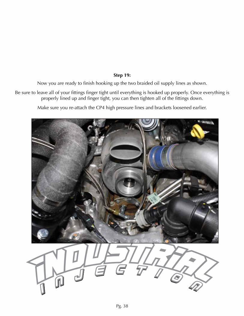
Step 19:
Now you are ready to finish hooking up the two braided oil supply lines as shown.
Be sure to leave all of your fittings finger tight until everything is hooked up properly. Once everything is properly lined up and finger tight, you can then tighten all of the fittings down.
Make sure you re-attach the CP4 high pressure lines and brackets loosened earlier.

Pg. 39
Step 20:
Installing the new hot pipe and down pipe.
Make sure the V-Band clamp on the Hot Pipe is lose. This will allow you to make fine little adjustments needed when you drop the turbo into place.

Pg. 40
Slide the heat wrapped aftermarket down pipe along the heat shield until it drops off the back and is lying on top of the heat shield.
Pg. 41
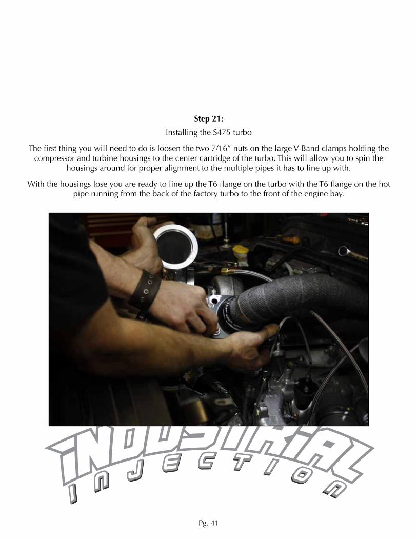
Step 21:
Installing the S475 turbo
The first thing you will need to do is loosen the two 7/16” nuts on the large V-Band clamps holding the compressor and turbine housings to the center cartridge of the turbo. This will allow you to spin the
housings around for proper alignment to the multiple pipes it has to line up with.
With the housings lose you are ready to line up the T6 flange on the turbo with the T6 flange on the hot pipe running from the back of the factory turbo to the front of the engine bay.
Pg. 42
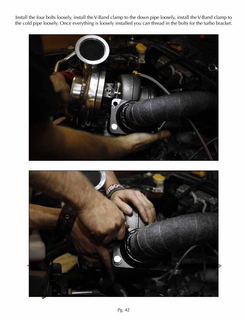
Install the four bolts loosely, install the V-Band clamp to the down pipe loosely, install the V-Band clamp to the cold pipe loosely. Once everything is loosely installed you can thread in the bolts for the turbo bracket.

Pg. 43
Tighten up the two 13mm bolts on the bottom of the turbo first, then proceed to tighten up your V-Band clamps and the 7/16” nuts on the large clamps of the Compressor and turbine housings, as well as the
T6 flange bolts.
Install the provided intake filter elbow on the front of the Turbo. You will need to use a red hot knife to cut a rectangular hole in the rubber elbow for the MASS airflow sensor. This rubber is very hard, you can
use a drill bit to pre drill holes for the two screw holding the sensor in.
Pg. 44
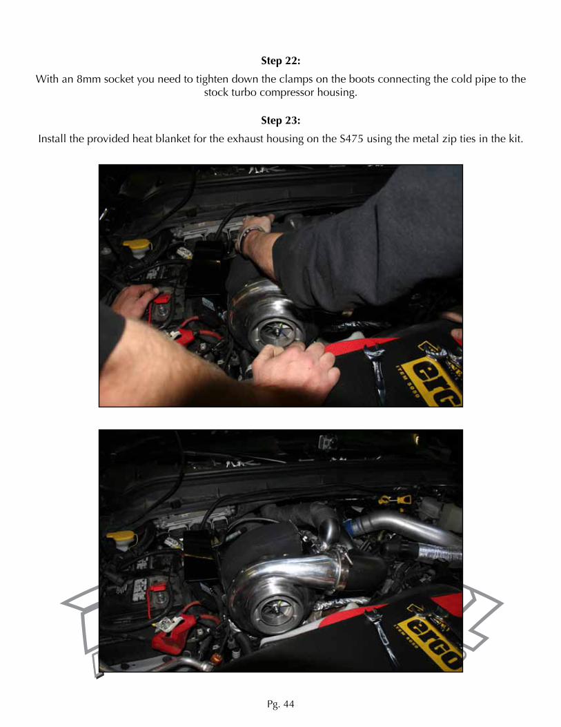
Step 23:
Install the provided heat blanket for the exhaust housing on the S475 using the metal zip ties in the kit.
Step 22:
With an 8mm socket you need to tighten down the clamps on the boots connecting the cold pipe to the stock turbo compressor housing.
Pg. 45
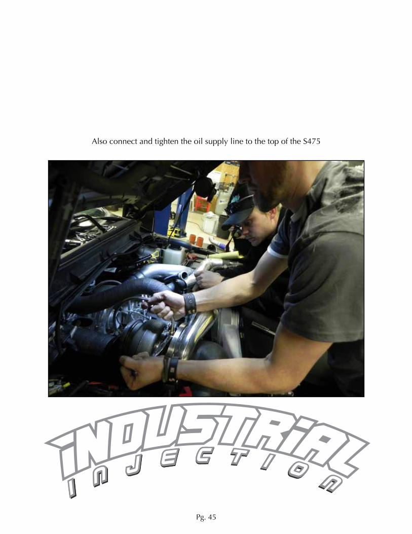
Also connect and tighten the oil supply line to the top of the S475

Pg. 46
Step 24:
Drilling and tapping the upper oil pan.
You need to remove the lower oil pan using an 8mm socket. Remove the oil filter and the oil filter housing.

Pg. 47
You need a 37/64 drill bit to drill a hole as shown in this exact location. Once the hole is drilled use a 3/8 by 18NPT tap if the tap becomes hard to turn, reverse it and clear any debris from the threads before
proceeding. This will prevent stripping the threads.

Pg. 48
Thread in the provided fitting and cut the oil return line to the proper length before sliding it onto the fitting.

Pg. 49
Go over everything you have installed and be sure all bolts and clamps are properly tightened.
Fire up the engine and use a bottle of soapy water to check for any boost leaks by spraying down all of your connections. If you see bubbles you will know there is a clamps or bolt that needs to be tightened.
Step 25:
Finish your installation by attaching the lower portion of the down pipe with the provided clamps.