
Industrial HSPA Cellular Routers - Cell Phone … HSPA Cellular Routers NTC-6000 SERIES. NTC-6000...
63
USER GUIDE NETCOMM CALLDIRECT™ SERIES Industrial HSPA Cellular Routers NTC-6000 SERIES
-
Upload
nguyenngoc -
Category
Documents
-
view
218 -
download
2
Transcript of Industrial HSPA Cellular Routers - Cell Phone … HSPA Cellular Routers NTC-6000 SERIES. NTC-6000...

USER GUIDE
NETCOMM CALLDIRECT™ SERIES
Industrial HSPA Cellular Routers NTC-6000 SERIES

NTC-6000 Series User Guide YML60002 www.netcomm.com.au
Wireless M2M
PrefaceThis manual provides information relating to the installation, operation, and application of this device. The individual reading this manual is presumed to have a basic understanding of telecommunications terminology and concepts.
If you find the product to be broken or malfunctioning, please contact technical support for immediate service by email at [email protected]
For product updates, new product releases, manual revisions, or software upgrades, please visit our website at www.netcomm-commercial.com.au
Important Safety InstructionsWith reference to unpacking, installation, use and maintenance of your electronic device, the following basic guidelines are recommended:
Do not use or install this product near water to avoid fire or shock hazard. For example, near a bathtub, kitchen sink, laundry tub, or near a swimming pool. Also, do not expose the equipment to rain or damp areas (e.g. a wet basement).
Do not connect the power supply cord on elevated surfaces. Allow it to lie freely. There should be no obstructions in its path and no heavy items should be placed on the cord. In addition, do not walk on, step on or mistreat the cord.
To safeguard the equipment against overheating, make sure that all openings in the unit that offer exposure to air are unobstructed.
WARNING
• Disconnect the power line from the device before servicing.
Copyright
Copyright©2011 NetComm Limited. All rights reserved. The information contained herein is proprietary to NetComm Limited. No part of this document may be translated, transcribed, reproduced, in any form, or by any means without prior written consent of NetComm Limited.NOTE: This document is subject to change without notice.
Save Our EnvironmentWhen this equipment has reached the end of its useful life, it must be taken to a recycling centre and processed separately from domestic waste.
The cardboard box, the plastic contained in the packaging, and the parts that make up this router can be recycled in accordance with regionally established regulations. Never dispose of this electronic equipment along with your household waste. You may be subject to penalties or sanctions under the law. Instead, ask for disposal instructions from your municipal government.
Please be responsible and protect our environment.
Revision History
Level Date History
1.0 June 2010 Internal Release Version (FW 1.52)
2.0 November 2010 Initial Public Release (FW v1.57)
2.1 February 2011 Update - GPS and modem configuration (FW v1.7.0)
2.2 June 2011 Update - SMS Tools configuration (FW v1.7.1.5)

YML6000 NTC-6000 User Guidewww.netcomm.com.au 3
NetComm CallDirect™ Series - NTC-6000 Series
Table of ContentsIntroduction ������������������������������������������������������������������������������������������������������������������������������������������������������������������������������������������������5
1.1 Hardware overview ....................................................................................................................................................................................................6
Configuring your Router �����������������������������������������������������������������������������������������������������������������������������������������������������������������������������92.1 Inserting the SIM card ...............................................................................................................................................................................................92.2 Setting up the cellular router ......................................................................................................................................................................................92.3 Preparing your computer .........................................................................................................................................................................................102.4 Accessing your router’s configuration pages ............................................................................................................................................................142.5 Unlocking the SIM ...................................................................................................................................................................................................15
Band / Provider Selection ������������������������������������������������������������������������������������������������������������������������������������������������������������������������203.1 Locking to a specific band ......................................................................................................................................................................................203.2 Choosing your provider manually.............................................................................................................................................................................20
How to Establish a Connection to the Cellular Network ������������������������������������������������������������������������������������������������������������������������214.1 Initiating a PPP connection directly from the router ..................................................................................................................................................214.2 Initiating a connection using the router in transparent PPPoE mode .......................................................................................................................23
5Ethernet Related Commands�����������������������������������������������������������������������������������������������������������������������������������������������������������������245.1 How to configure the Ethernet IP address ...............................................................................................................................................................245.2 How to configure DNS Masquerading .....................................................................................................................................................................245.3 How to configure the DHCP Server .........................................................................................................................................................................245.4 How to configure your device’s IP address manually (no DHCP) .............................................................................................................................26
Virtual Private Networks ���������������������������������������������������������������������������������������������������������������������������������������������������������������������������276.1 How to configure a PPTP / GRE connection .............................................................................................................................................................27
Routing Configuration ������������������������������������������������������������������������������������������������������������������������������������������������������������������������������307.1 Configuring Static Routes .........................................................................................................................................................................................307.2 How to configure RIP ................................................................................................................................................................................................317.3 How to configure VRRP ............................................................................................................................................................................................317.4 NAT configuration .....................................................................................................................................................................................................32
Services Features �������������������������������������������������������������������������������������������������������������������������������������������������������������������������������������348.1 How to configure the dynamic DNS client .................................................................................................................................................................348.2 How to configure SNMP ...........................................................................................................................................................................................348.3 How to configure NTP ..............................................................................................................................................................................................358.4 How to configure the Periodic Ping Reset Monitor ....................................................................................................................................................358.5 How to configure a Periodic Reset Timer ..................................................................................................................................................................368.6 How to configure the modem ...................................................................................................................................................................................368.7 GPS ..........................................................................................................................................................................................................................37
SMS Tools �������������������������������������������������������������������������������������������������������������������������������������������������������������������������������������������������399.1 SMS Tools Setup ......................................................................................................................................................................................................409.2 SMS Configuration for Redirection ............................................................................................................................................................................419.3 SMS Configuration for Remote Diagnostics ..............................................................................................................................................................419.4 New Message ...........................................................................................................................................................................................................419.5 Inbox/Outbox ............................................................................................................................................................................................................429.6 Diagnostics and Command Execution Setup ............................................................................................................................................................429.7 Security ....................................................................................................................................................................................................................449.8 SMS Command format .............................................................................................................................................................................................449.9 Replies......................................................................................................................................................................................................................449.10List of valid commands (which can be used in conjunction with the execute command): ..........................................................................................459.11List of valid variables: ...............................................................................................................................................................................................459.12SMS Diagnostics Examples ......................................................................................................................................................................................46
System Features ��������������������������������������������������������������������������������������������������������������������������������������������������������������������������������������4810.1 Remote administration ............................................................................................................................................................................................4810.2 To save a copy of the routers configuration .............................................................................................................................................................4910.3 To restore a copy of the routers configuration .........................................................................................................................................................4910.4 To restore the routers configuration to the factory defaults ......................................................................................................................................4910.5 To upgrade the router’s system or recovery console software version .....................................................................................................................50
11 Troubleshooting �����������������������������������������������������������������������������������������������������������������������������������������������������������������������������������5511.1 Viewing the system log ...........................................................................................................................................................................................5511.2 Common problems and solutions. ...........................................................................................................................................................................55
Specifications ������������������������������������������������������������������������������������������������������������������������������������������������������������������������������������������5812.1 Hardware specifications ..........................................................................................................................................................................................5812.2 RJ-45 Ethernet port integration parameters.............................................................................................................................................................5812.3 RS-232 serial port integration parameters ...............................................................................................................................................................5912.4 Custom Application and Scripting ...........................................................................................................................................................................59
Legal & Regulatory Information ���������������������������������������������������������������������������������������������������������������������������������������������������������������61

Introduction

YML6000 NTC-6000 User Guidewww.netcomm.com.au 5
NetComm CallDirect™ Series - NTC-6000 Series
IntroductionThank you for purchasing an Industrial HSPA Cellular Network Router from NetComm. This manual illustrates how to set-up and configure your router appropriately for your chosen task. The router is primarily managed and configured via a web browser. This manual will take you through the steps required to configure and use your unit correctly.
Additionally, the router may be configured via the serial (V.24) port using “AT” (V.250) commands. This method of operation is further detailed in the document: NTC-6000Series_V250(AT)Manual_V1-1-0.
1.1 OverviewAn NTC-6000 series router allows you to build wide area networks utilising the superior speeds supported by 3G UMTS networks. Employing an embedded 3G modem module the router offers downlink speeds of up to 7.2Mbps and uplink speeds of up to 5.76Mbps. The NTC-6000 series provides the user a point-to-point or point-to-multi-point communications link in a single, compact and resilient unit. As a fully featured cellular router, it supports a large number of communication interfaces and protocols to meet the demands of today’s telemetry and WAN applications.
Designed with remote installation in mind the NTC-6000 series supports multi-level system monitoring giving the user peace of mind the device will keep the lines of communication up and open.
In the event of system corruption, a built-in recovery mode provides the facility to re-install the system software to the router and resume normal operations quickly. Using the recovery console is further detailed in the document NTC-6XXX Firmware Upgrade VX.X.X.pdf that is part of all NTC-6000 series firmware upgrade packs released, which are available for download in the support section of our website: www.netcomm-commercial.com.au/.
1.2 Features Intelligent industrial cellular router platform supporting various networks and service types UMTS/HSDPA/HSUPA & GSM/
GPRS/EDGE
High-speed Atmel 400MHz ARM9-based Microcontroller
Embedded Sierra HSPA modem module MC8790V (NTC-6908) or MC8792V (NTC-6909) with Qualcomm MSM6290 chipset
Wide area data access speeds in 3G mode up to 7.2Mbps in downlink (HSDPA category 8) and up to 5.76Mbps in uplink (HSUPA category 6)
Wide area data access speeds in 2G mode up to 236 kbps (EDGE multi slot class 12)
Antenna diversity to improve fringe performance on global HSPA networks
Rugged metal housing and temperature-hardened electronic components - extended operating temperature -30 to 70°C
Wide input voltage range 8 – 28 V DC suitable for diverse environments and applications
Embedded Linux operating system allowing for the installation of custom applications
Web user interface for easy centralized configuration and management from any computer or smartphone with multi-level administrator access
10/100Base-TX port for Ethernet connections
RS-232 port for connection to serial devices
PAD mode via the serial port
Integrated GPS for remote position tracking -location mapping via Google Maps
VPN client for establishing a secure connection over public networks
Supports SNMP with cellular specific MIB, PPPoE, MAC /NET address filtering,
DHCP/DHCP relay, Dynamic DNS and advanced routing RIP/VRRP
Supports NAT, Port forwarding and a DMZ host
Configurable APN profiles (drop-down list)
Supports manual network scan
System monitoring, diagnostic log viewer.
Web user interface for easy centralized configuration and management from any PC or smart phone
Remote diagnostics, configuration and firmware update over the air (FOTA)
SMS client allowing advanced SMS diagnostics and command execution
Software Development Kit (SDK) for the creation of custom applications
Dual system management - recovery mode to restore router system software in the event of corruptions locally or remotely

NTC-6000 Series User Guide YML60006 www.netcomm.com.au
Wireless M2M
1.3 Hardware overview1�3�1 Overview of indicator lights
There are a total of five LED’s on the router, one red, one amber and three green.
Listed below are the specifications of the LED’s and their corresponding colours.
LED Display Description
POWER (red) Solid ON The red Power LED indicates power is applied to the DC
power input jack.
Tx Rx (amber) Solid ON The amber LED will light upon data being sent to or received
from the cellular network.
DCD (green) Solid ON The green Data Carrier Detect LED illuminates to indicate a
data connection.
Service Type (green) The green LED will illuminate when cellular network coverage is detected.
Solid ON 3G: Indicates UMTS/HSPA available coverage
Flashing EDGE: Indicates EDGE available coverage
Off 2G: Indicates GSM/GPRS available coverage only.
RSSI (green) This green LED shows Received Signal Strength. There are three possible states that the RSSI LED can operate
in, based upon signal level.
Solid ON Strong:Indicates the RSSI level is -86dbm
Flashing once per second Medium: Indicates the RSSI level is -110dbm and -86dbm
Off Poor: Indicates the RSSI level is less than -110dbm
YML6000 NTC-6000 User Guidewww.netcomm.com.au 7
NetComm CallDirect™ Series - NTC-6000 Series
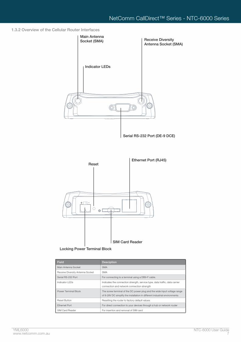
1�3�2 Overview of the Cellular Router Interfaces
Indicator LEDs
Main Antenna Socket (SMA)
Serial RS-232 Port (DE-9 DCE)
Ethernet Port (RJ45)Reset
SIM Card Reader
Locking Power Terminal Block
Receive Diversity Antenna Socket (SMA)
+ -
Field Desciption
Main Antenna Socket SMA
Receive Diversity Antenna Socket SMA
Serial RS-232 Port For connecting to a terminal using a DB9-F cable.
Indicator LEDs Indicates the connection strength, service type, data traffic, data carrier
connection and network connection strength
Power Terminal Block The screw terminal of the DC power plug and the wide input voltage range
of 8-28V DC simplify the installation in different industrial environments
Reset Button Resetting the router to factory default values
Ethernet Port For direct connection to your devices through a hub or network router
SIM Card Reader For insertion and removal of SIM card

Configure
YML6000 NTC-6000 User Guidewww.netcomm.com.au 9
NetComm CallDirect™ Series - NTC-6000 Series
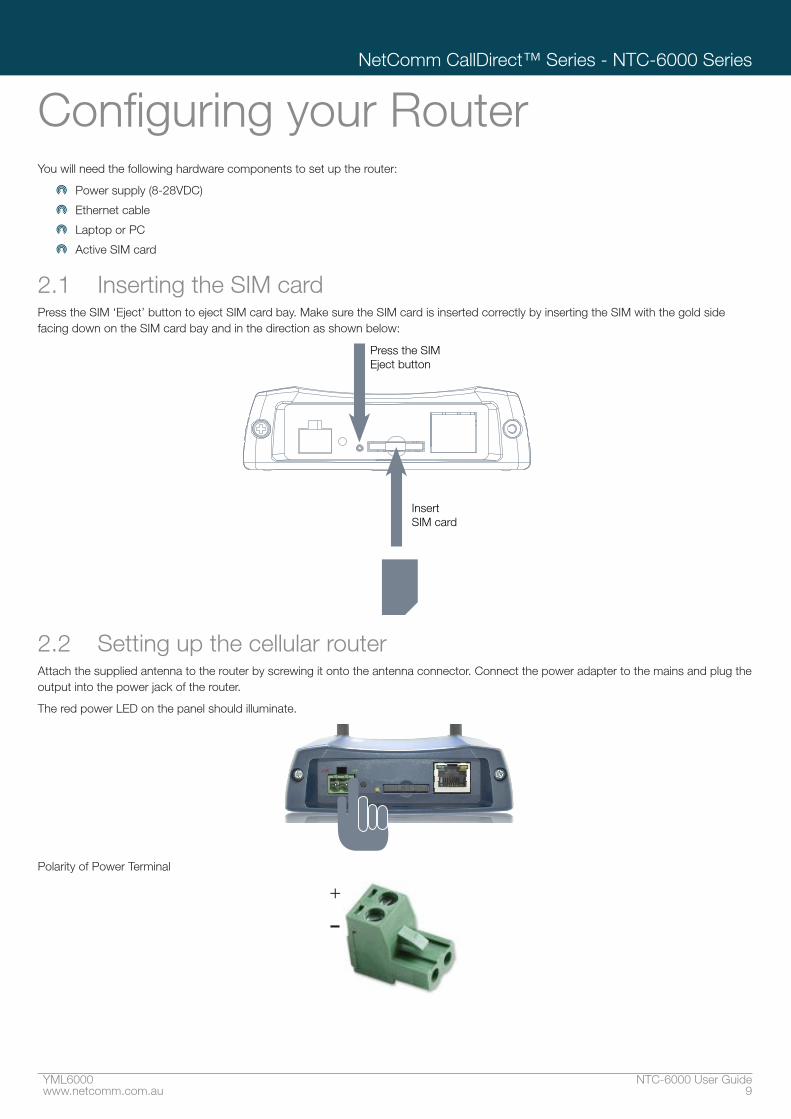
Configuring your RouterYou will need the following hardware components to set up the router:
Power supply (8-28VDC)
Ethernet cable
Laptop or PC
Active SIM card
2.1 Inserting the SIM cardPress the SIM ‘Eject’ button to eject SIM card bay. Make sure the SIM card is inserted correctly by inserting the SIM with the gold side facing down on the SIM card bay and in the direction as shown below:
Insert SIM card
Press the SIM Eject button
2.2 Setting up the cellular routerAttach the supplied antenna to the router by screwing it onto the antenna connector. Connect the power adapter to the mains and plug the output into the power jack of the router.
The red power LED on the panel should illuminate.
+VE -VE
Polarity of Power Terminal
-+

NTC-6000 Series User Guide YML600010 www.netcomm.com.au
Wireless M2M
2.3 Preparing your computerConnect one end of the supplied Ethernet cable to the Ethernet port of your router. Connect the other end of the cable to the LAN
port of your computer. Configure your PC’s Ethernet interface to use a dynamically assigned IP address by doing the following.
2.3.1 Ethernet interface configuration in Windows XPClick on the Start button, then the Control Panel and then Network Connections.
Right click on Local Area Connection and select Properties to open the configuration dialogue box of the Local Area Connection as below:
Find and click Internet Protocol (TCP/IP) from the protocol list box and then click the Properties button. The TCP/IP configuration window will pop up as illustrated below.
Under General tab, select radio button ‘Obtain an IP address automatically’ and ‘Obtain DNS server address automatically’.
Then press the OK button to close TCP/IP configuration window and then press the Close button to complete the computer preparation for the router.

YML6000 NTC-6000 User Guidewww.netcomm.com.au 11
NetComm CallDirect™ Series - NTC-6000 Series
2.3.2 Ethernet interface configuration in Windows VistaClick on the Start button, then the Control Panel and then Network and Sharing Center.
In the Manage network connections, click on “Manage network connections” to continue.
Single RIGHT click on “Local Area connection”, then click “Properties”.

NTC-6000 Series User Guide YML600012 www.netcomm.com.au
Wireless M2M
The screen will display the information “User Account Control” and click “Continue” to continue and then double click on “Internet Protocol Version 4 (TCP/IPv4)”.
Click“Obtain an IP address automatically” and “Obtain DNS server address automatically” then click on “OK” to continue.
Click on “OK” to complete the computer preparation for the router.
YML6000 NTC-6000 User Guidewww.netcomm.com.au 13
NetComm CallDirect™ Series - NTC-6000 Series
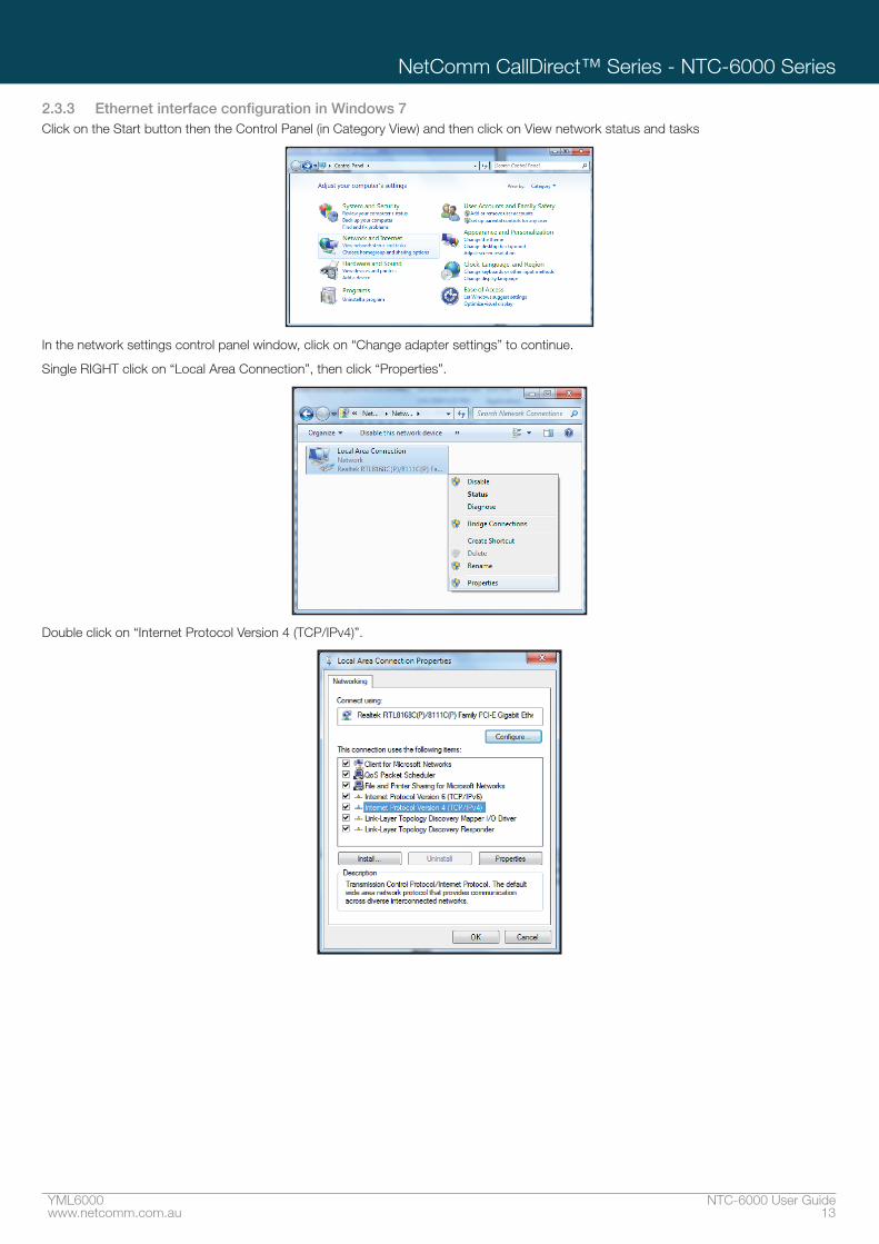
2.3.3 Ethernet interface configuration in Windows 7Click on the Start button then the Control Panel (in Category View) and then click on View network status and tasks
In the network settings control panel window, click on “Change adapter settings” to continue.
Single RIGHT click on “Local Area Connection”, then click “Properties”.
Double click on “Internet Protocol Version 4 (TCP/IPv4)”.

NTC-6000 Series User Guide YML600014 www.netcomm.com.au
Wireless M2M
Click on “Obtain an IP address automatically” and “Obtain DNS server address automatically” then click on “OK” to continue.
Click on “OK” to complete the computer preparation for the router.
2.4 Accessing your router’s configuration pagesFurthermore, there are two system management accounts for maintaining the system, root and admin, each of which has slightly different levels of management capabilities. The root manager account is empowered with full privileges while the admin manager (administrator) can manage all settings of the router except functions like Firmware Upgrade, Device Configuration Backup and Restore and Reset router to factory default.
To login to the router in root manager mode, please use the following login details:
http://192�168�20�1
USERNAME: root
PASSWORD: admin
To login to the router in admin manager mode, please use the following default login details.
http://192�168�20�1
USERNAME: admin
PASSWORD: admin
NOTE – Whenever you make changes, please refresh your web page to prevent errors occurring due to caching.
Below illustrates the steps required to access the router’s web browser configuration:
1. Open your web browser (e.g. Internet Explorer/Firefox/Safari) and navigate to http://192.168.20.1/
2. Click Login and type “admin” (without quotes) in the Username and Password fields. Then click on Submit.

YML6000 NTC-6000 User Guidewww.netcomm.com.au 15
NetComm CallDirect™ Series - NTC-6000 Series
2.5 Unlocking the SIMIf the SIM card is locked you will need to unlock it with a PIN provided with your SIM card. You can find out if the SIM is locked by viewing the SIM Status on the Status page:
If the SIM Status is SIM locked as above, you should be automatically redirected to the SIM unlock page. If not, then do the following: Click on the “Internet Settings” menu followed by “WWAN (3G)“ and then “SIM Security”:
When you click on the ‘SIM Security’ menu item you should see the following message:-
Click OK
Next, enter the PIN code and confirm the PIN code. Then click Save.

NTC-6000 Series User Guide YML600016 www.netcomm.com.au
Wireless M2M
Now Click on the link and the Home Status page should look as below with SIM Status ‘SIM OK’:
2�5�1 Enter PUKIf after three incorrect attempts at entering the PIN code, you are requested to enter a PUK code:
You will need to contact your carrier to obtain this number.
Your carrier will issue you a PUK code to enable you to unlock the SIM and enter a new PIN code. Enter the new PIN and PUK codes, click Save.
If you have entered the PUK correctly you should see the following message:

Band / Provider Selection

NTC-6000 Series User Guide YML600018 www.netcomm.com.au
Wireless M2M
Now click on the ”Status” menu item at the top left-hand side of the page. It should reflect the screenshot below and show a SIM Status of ‘SIM OK’
2�5�2 The ‘Remember PIN’ featureThis feature allows the router to automatically send the PIN to the SIM each time the SIM asks for it (usually at power up).
This enables the SIM to be PIN Locked (to prevent unauthorised re-use of the SIM elsewhere), while still allowing the router to connect to the cellular service.
When this feature is enabled the PIN entered by the user when they set the “Remember PIN” feature is encrypted and stored locally in the router. The next time the SIM asks the router for the PIN the router decrypts the PIN and automatically sends it to the SIM without user intervention.
When this feature is disabled and the SIM is PIN locked, the user must manually enter the PIN via the router‘s configuration interface. This is clearly not desirable where the router is unattended.

Connection

NTC-6000 Series User Guide YML600020 www.netcomm.com.au
Wireless M2M
Band / Provider Selection3.1 Locking to a specific bandYou may want to lock the router to a specific band. To do this, click on the “Internet Settings” menu followed by “WWAN (3G)“ and then the “Band / Provider” menu item on the right..
You may want to do this if you’re using the router in a country with multi frequency networks that may not all support HSPA. You can select the router to only connect on the network frequencies that suit your requirements.
Make your selection from the “Change Band:” drop down list.
The following band settings options are applicable.
Band Selection Options - NTC-6908
UMTS 850MHZ ONLY = UMTS 850 MHz Only
WCDMA ALL = UMTS 850/2100/1900MHz
UMTS 850MHZ, 2G = UMTS 850 MHz GSM/EDGE/GPRS 900/1800/1900MHz
2G = GSM/EDGE/GPRS 900/1800/1900MHz
ALL BANDS (AUTOBAND) = UMTS 850/2100/1900MHz GSM/EDGE/GPRS 850/900/1800/1900MHz
Band Selection Options - NTC-6909
UMTS 900MHZ ONLY = UMTS 900 MHz Only
WCDMA ALL = UMTS 900/2100/1900MHz
UMTS 900MHz, 2G = UMTS 900 MHz GSM/EDGE/GPRS 850/900/1800/1900MHz
2G = GSM/EDGE/GPRS 850/900/1800/1900MHz
ALL BANDS (AUTOBAND) = UMTS 850/900/2100/1900MHz GSM/EDGE/GPRS 850/900/1800/1900MHz
Click Save to confirm your new band settings.NOTE: After changing the band, if the change is not reflected on the frequency field on the “Status” page then you may need to reboot the router.
3.2 Choosing your provider manuallyThe default setting is “Automatic”. To scan manually for available cellular network operators (providers) follow the steps below:
1. If you are currently connected to the internet, disconnect your session and ensure “Auto Connect” is disabled in the current cellular connection profile you are using (You can check this by clicking on the “Internet Settings” menu followed by “WWAN (3G)“ and then the “Connection” menu item on the right)
2. Select the operator mode Manual
3. Click on the Scan button. A list of cellular operators in the vicinity of your router should appear below
4. Select your chosen provider from the list of detected operators and click the Apply button
The router will then use the chosen operator to attempt to connect to the cellular service profile you have elected to use.

YML6000 NTC-6000 User Guidewww.netcomm.com.au 21
NetComm CallDirect™ Series - NTC-6000 Series
How to Establish a Connection to the Cellular NetworkThis section describes how to set up the router to initiate a WWAN connection. There are 2 different ways to set up a WWAN connection via PPP:
Initiating the PPP Connection directly from the router (most common).
Initiating the PPP Connection from a different PPP client (i.e. laptop or router) with the router running in transparent PPPoE mode.
4.1 Initiating a PPP connection directly from the routerThe status page of the router should be displayed as below. Please ensure that the SIM Status is ‘SIM OK’ before you initiate a WWAN connection.
Click on the “Internet Settings” menu followed by “WWAN (3G)“ and then the “Connection” menu item on the right.
4.1.1 To connect using a connection profileThe router supports multiple APN profiles; these profiles allow you to configure the settings that the router will use to connect to the cellular network.
First examine the list of configured profiles
Select the profile that you wish to connect with and make sure that the APN name field is correct. This is very important
Select “Enable” for the Auto Connect option and click Save
From now on, Auto Connect will remain enabled and the router will automatically connect unless you come back to this page and disable it.
Ethernet Related Commands

YML6000 NTC-6000 User Guidewww.netcomm.com.au 23
NetComm CallDirect™ Series - NTC-6000 Series
4.1.2 To confirm successful connection
Now click on the link to return to the status page. Please pay close attention to WWAN section on the page. The WWAN status should be ’’up”. The Local field shows the current IP address that the network has allocated for the router.
Congratulations. Your new Cellular Router is now ready to use!
4.2 Initiating a connection using the router in transparent PPPoE modeTo enable PPPoE mode, firstly ensure the “Auto Connect” is disabled in all the profiles on the “Connection” configuration page by clicking on the “Internet Settings” menu followed by “WWAN (3G)“ and then the “Connection” menu item on the right and select each connection profile and disable the Auto Connection option and save the updated settings..
Select “Enable” to enable PPPoE.
Specify the APN you wish to use to suit your carrier
In addition you may specify an optional “Service Name”. When a “Service Name” is specified the connected device must use the same service name when connecting. This facility is particularly useful if you have more than one PPPoE router or modem on a single Ethernet network.
Finally click “Save” to save your settings and enable PPPoE.

NTC-6000 Series User Guide YML600024 www.netcomm.com.au
Wireless M2M
5 Ethernet Related Commands5.1 How to configure the Ethernet IP addressThis facility is available by clicking on the “Internet Settings” menu followed by “LAN“ and then the “IP Setup” menu item on the right.
The default IP of the Ethernet port is 192.168.20.1 with subnet mask 255.255.255.0.
If you wish to change this then simply enter the new IP address and click on the Save button at the bottom of the page.
Since the IP address has changed you will have to re-enter the new IP address configured in your browser to access the configuration pages.
5.2 How to configure DNS MasqueradingDNS masquerading allows the router to forward DNS requests to dynamically assigned DNS servers. Clients on the router’s LAN can then use the router as a DNS server without needing to know of the dynamically assigned DNS servers assigned by the cellular network.
There should be no need to disable this feature in most cases, however, if you need to do so simply select “Disable” and click Save.
5.3 How to configure the DHCP ServerUse the following procedure to change the router’s DHCP server default settings. Ensure your PC’s Ethernet connector is configured to automatically obtain an IP and DNS server address.
When you plug in the Ethernet cable to your PC, the router should automatically assign it an IP address within 10-15 seconds. Please be aware that you will be sharing the bandwidth of the router between all connected devices. You can manually set DNS1 and DNS2 or if DNS Masquerade is enabled the DHCP DNS1 address will automatically be set to the router’s LAN address.
This example has a start address of 100, an end address of 199, lease time of 86,400 seconds, and uses the DNS servers that are auto-assigned by the network upon connection.
If you do not enter the DNS1 and DNS2 addresses manually, then to browse the Internet from your Ethernet connected device you must enable DNS Masquerade (see above).
Upon enabling DNS Masquerade, you will notice that the DNS1 address is automatically set to the IP address of the Ethernet port. DNS addresses are then automatically assigned by the connection to the network.

Virtual Private Networks

NTC-6000 Series User Guide YML600026 www.netcomm.com.au
Wireless M2M
5.3.1 How to configure static DHCP assignmentsThis facility is available by clicking on the “Internet Settings” menu followed by “LAN“ and then the “DHCP” menu item on the right.
You may assign a particular IP address to a specific device every time that device makes a DHCP request as follows:
a. Click Add
b. Enter a name for the computer or device
c. Enter the computer or devices’ MAC address
d. Enter the IP address to assign
e. Click Save
5.4 How to configure your device’s IP address manually (no DHCP)If your device has a static IP address set, you can configure your device to work with the router by manually configuring your device to the following settings:
Set your device’s IP address to any valid IP between 192.168.20.2 and 192.168.20.99 or disable the DHCP server and use any address. Do not use the IP address assigned to the router’s Ethernet interface.
Set your device’s subnet to: 255.255.255.0.
Set your Gateway to the IP address of the router’s Ethernet interfacer: 192.168.20.1
DNS (if required) set to 192.168.20.1 or manually set to your carrier’s DNS Servers.

YML6000 NTC-6000 User Guidewww.netcomm.com.au 27
NetComm CallDirect™ Series - NTC-6000 Series
Virtual Private NetworksA Virtual Private Network (VPN) is a tunnel providing a private link between two networks or devices over a public network. Data to be sent via a VPN needs to be encapsulated and as such is generally not visible to public network.
PPTP and GRE are common encapsulation methods used to create a virtual private network (VPN) over public networks.
The advantages of the VPN feature includes:
Data Protection
AccessControl
Data Origin Authentication
Data Integrity
6.1 How to configure a PPTP / GRE connectionThis facility is available by clicking on the “Internet Settings” menu followed by the “VPN” menu item.
There are a couple of steps that you need to take before obtaining a PPTP/GRE interface:
There are a few configuration steps you will need to complete before obtaining a PPTP/GRE connection:
1: Get connected to the cellular broadband network:To do this click on the “Internet Settings” menu followed by “WWAN (3G)” and then the “Connection” menu item on the right and in the PPP Profile Connect section, click ‘enable’ for the appropriate profile.
To check that the PPP interface is connected, click on the Status menu at the top of the page and check the PPP status. The PPP status should be shown as “UP”.
For more details on enabling a data connection refer to the Connection configuration section of this guide.

Routing Configuration

YML6000 NTC-6000 User Guidewww.netcomm.com.au 29
NetComm CallDirect™ Series - NTC-6000 Series
2: Enable PPTP:Click on the VPN menu item (By clicking on the “Internet Settings” menu followed by the “VPN” menu item) and enter the PPTP/GRE server IP address and user name and passwords in the appropriate boxes and click “Enable“ and then “Save”.
To check that the PPTP/GRE interface is up, click on the Status menu and in the PPTP/GRE section, the status should be shown as “UP”.NOTE – It may be necessary to add a static route. The Gateway IP address is the same as the PPTP/GRE server address. Enter the PPTP/GRE server IP address in the Gateway IP address box.
Example:If the PPTP/GRE server address is 203.44.251.100 and the IP address of the local PPTP/GRE interface is 10.1.3.42 (i.e. a 10.0.0.0 address) then in the static routes section, you would need to enter the following:
10.0.0.0 in the destination IP address box
255.0.0.0 in the IP subnet mask box
203.44.251.100 in the Gateway IP address box.
1 in the metric box.
Editing the PPTP/GRE credentials:If you need to edit the PPTP/GRE credentials you need to disable the existing PPTP/GRE connection and then enter the new credentials and re-enable the connection.
Disabling PPTP/GRE:If you want to completely disconnect both the PPP and PPTP/GRE interface from the network then it is best to first disable the PPTP/GRE interface simply by clicking “Disable” and hitting “Save” and then disabling the PPP connection by clicking “Disable” for the appropriate profile number on the “Connection” configuration page.
However, if you want to leave the PPTP/GRE enabled for future use then just disable the PPP connection on the “Connection” configuration page. The next time a PPP connection is enabled the PPTP/GRE interface will also come up.Note: GRE TTL (Time to Live) limit is 255 on the period of transmissions.

NTC-6000 Series User Guide YML600030 www.netcomm.com.au
Wireless M2M
Routing Configuration7.1 Configuring Static RoutesThis facility is available by clicking on the “Internet Settings” menu followed by “Routing“ and then the “Static” menu item on the right.
Some routes are added by default by the router on initialisation such as the Ethernet subnet route for routing to a device on the Ethernet subnet. A PPP route is also added upon obtaining a WAN PPP connection.
However, if you have other routers (hence networks) on the Ethernet subnet for example, you may want to add some more static routes.
7�1�1 Adding Static Routes
Enter the values in the fields as above
Click ADDNOTE: You must increment the “Route no” by 1 for each route in the “Route no” field otherwise that route will be overwritten.
The Active Routing table at the bottom will show the new route added as shown below:
Example:If you have another router on the Ethernet side of the router with a gateway of 192.168.20.5 that interfaces to network 10.123.0.0/16 and you want to get to a device on that network then you enter:
10.123.0.0 in the Destination IP address field 255.255.0.0 in the IP Subnet Mask field
192.168.20.5 in the Gateway IP address field
The lower the metric value the higher the priority this routes has over other routes.
7�1�2 Deleting Static Routes
Select the “Delete Entry” text (in blue) for the route as shown above.
YML6000 NTC-6000 User Guidewww.netcomm.com.au 31
NetComm CallDirect™ Series - NTC-6000 Series
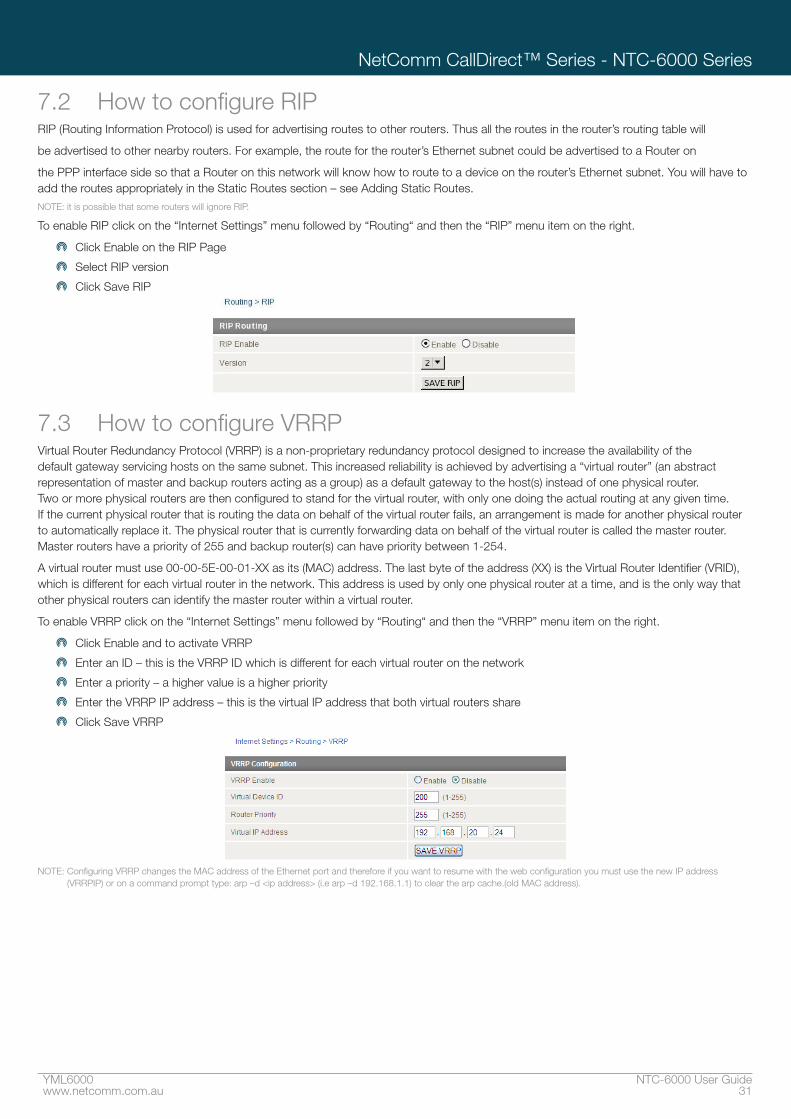
7.2 How to configure RIPRIP (Routing Information Protocol) is used for advertising routes to other routers. Thus all the routes in the router’s routing table will
be advertised to other nearby routers. For example, the route for the router’s Ethernet subnet could be advertised to a Router on
the PPP interface side so that a Router on this network will know how to route to a device on the router’s Ethernet subnet. You will have to add the routes appropriately in the Static Routes section – see Adding Static Routes.NOTE: it is possible that some routers will ignore RIP.
To enable RIP click on the “Internet Settings” menu followed by “Routing“ and then the “RIP” menu item on the right.
Click Enable on the RIP Page
Select RIP version
Click Save RIP
7.3 How to configure VRRPVirtual Router Redundancy Protocol (VRRP) is a non-proprietary redundancy protocol designed to increase the availability of the default gateway servicing hosts on the same subnet. This increased reliability is achieved by advertising a “virtual router” (an abstract representation of master and backup routers acting as a group) as a default gateway to the host(s) instead of one physical router. Two or more physical routers are then configured to stand for the virtual router, with only one doing the actual routing at any given time. If the current physical router that is routing the data on behalf of the virtual router fails, an arrangement is made for another physical router to automatically replace it. The physical router that is currently forwarding data on behalf of the virtual router is called the master router. Master routers have a priority of 255 and backup router(s) can have priority between 1-254.
A virtual router must use 00-00-5E-00-01-XX as its (MAC) address. The last byte of the address (XX) is the Virtual Router Identifier (VRID), which is different for each virtual router in the network. This address is used by only one physical router at a time, and is the only way that other physical routers can identify the master router within a virtual router.
To enable VRRP click on the “Internet Settings” menu followed by “Routing“ and then the “VRRP” menu item on the right.
Click Enable and to activate VRRP
Enter an ID – this is the VRRP ID which is different for each virtual router on the network
Enter a priority – a higher value is a higher priority
Enter the VRRP IP address – this is the virtual IP address that both virtual routers share
Click Save VRRP
NOTE: Configuring VRRP changes the MAC address of the Ethernet port and therefore if you want to resume with the web configuration you must use the new IP address (VRRPIP) or on a command prompt type: arp –d <ip address> (i.e arp –d 192.168.1.1) to clear the arp cache.(old MAC address).

NTC-6000 Series User Guide YML600032 www.netcomm.com.au
Wireless M2M
7.4 NAT configurationThis facility is available by clicking on the “Internet Settings” menu followed by “Routing“ and then the “NAT” menu item on the right. The router is in NAT mode by default.
7.4.1 How to configure Port ForwardingThis is only needed if you need to map inbound requests to a specific port on the WAN IP address to a device connected on the Ethernet interface, e.g. a web camera.
Enter the information as appropriate
Click Save
<MAPPING NO> 1 to as many as needed.
<PROTOCOL> TCP, UDP, All protocols
<SOURCE IP> Specifies either a “Friendly” IP address that is allowed to access the router or a wildcard IP address of 0.0.0.0 that allows all IP addresses to access the router.
<INCOMING PORT RANGE> External port(s) to listen to.
<DESTINATION IP> Local Area Network Address of device to forward inbound requests to.
<DESTINATION PORT RANGE> Local Area Network Port(s) to forward connections to.
Example:
Note:
If the “Incoming Port Range” specifies a single port (as above) then the destination port can be set to any port.
If the “Incoming Port Range” specifies a range of port numbers then the “Destination Port Range” MUST be the same as the “Incoming Port Range”.
Configured mappings are displayed as follows:
To delete a port forwarding rule, click on the corresponding “Delete Entry” link from the list of IP Mappings.
7.4.2 How to configure DMZThe Demilitarised Zone (DMZ) enables a device to utilise a direct connection to the WAN. This means any incoming connections are forwarded directly to this device.
This facility is available by clicking on the “Internet Settings” menu followed by “Routing“ and then the “DMZ” menu item on the right.

How to configure WEP/WPA-PSK/WPA2-PSK Wireless SecurityServices Features

NTC-6000 Series User Guide YML600034 www.netcomm.com.au
Wireless M2M
Services Features8.1 How to configure the dynamic DNS clientThis facility is available by clicking on the “Services” menu followed by the “DDNS” menu item on the right.
Dynamic DNS provides a method for the router to update an external name server with the current WAN IP address.
To configure dynamic DNS: Click Enable
Select the Dynamic DNS service that you wish to use. Enter your dynamic DNS account credentials.
Click Save
8.2 How to configure SNMPThis facility is available by clicking on the “Services” menu followed by the “SNMP” menu item on the right..
SNMP (Simple Network Management Protocol) is used to remotely monitor the router for conditions that may warrant administrative attention. It can be used to retrieve information from the router such as the signal strength, the system time, the interface status, etc.
To configure SNMP:
Click Enable
Enter Community Names or leave them as default
SNMP mandates that the SNMP agents should accept request messages only if the community string in the message matches its community name. Therefore, the management application should always communicate with the agents along with the associated community name. The default SNMP community names are “public” for read-only (GET) operations and “private” for read-write (SET) operations.
Click Save

YML6000 NTC-6000 User Guidewww.netcomm.com.au 35
NetComm CallDirect™ Series - NTC-6000 Series
8.3 How to configure NTPThis facility is available by clicking on the “Services” menu followed by the “NTP” menu item on the right..
The NTP (Network Time Protocol) settings allow your router to synchronise its internal clock with a global Internet Time server. This setting will affect functions such as System Log entries and Firewall settings.
8.4 How to configure the Periodic Ping Reset MonitorThis facility is available by clicking on the “Services” menu followed by the “System Monitor” menu item on the right..
The Periodic Ping Reset Monitor configures the router to transmit controlled ping packets to 1 or 2 user specified IP addresses. Should the router not receive responses to the pings, the router will reboot.
This works as follows:
A. After every “Periodic Ping Timer” configured interval, the router sends 3 consecutive pings to the “Destination Address”.
B If all 3 pings fail the router sends 3 consecutive pings to the “Second Address”.
C The router then sends 3 consecutive pings to the “Destination Address” and 3 consecutive pings to the “Second Address” every “Periodic Ping Accelerated Timer” configured interval.
D. If all accelerated pings in step C above fail the number of times configured in “Fail Count”, the router reboots.
E. If any ping succeeds the router returns to step A and does not reboot.Note: The “Periodic Ping Timer” should never be set to a value less than 60 seconds; this is to allow the router time to reconnect to the cellular network following a reboot.
8�4�1 Periodic Ping DisabledTo disable the Periodic Ping Reset Monitor simply set to “Fail Count” 0
8�4�2 Periodic Ping Enabled
An Example Setup:The setup below will ping 10.1.2.3 every 10 minutes, if it fails it then tries to ping 10.1.2.4, if that also fails it then accelerates the ping attempts to once every 60 seconds and if 3 successive ping attempts at the one minute interval fails, the router will reboot.
NOTE:The traffic generated by the periodic ping feature is counted as chargeable usage, please keep this in mind when selecting how often to ping.
NTC-6000 Series User Guide YML600036 www.netcomm.com.au
Wireless M2M
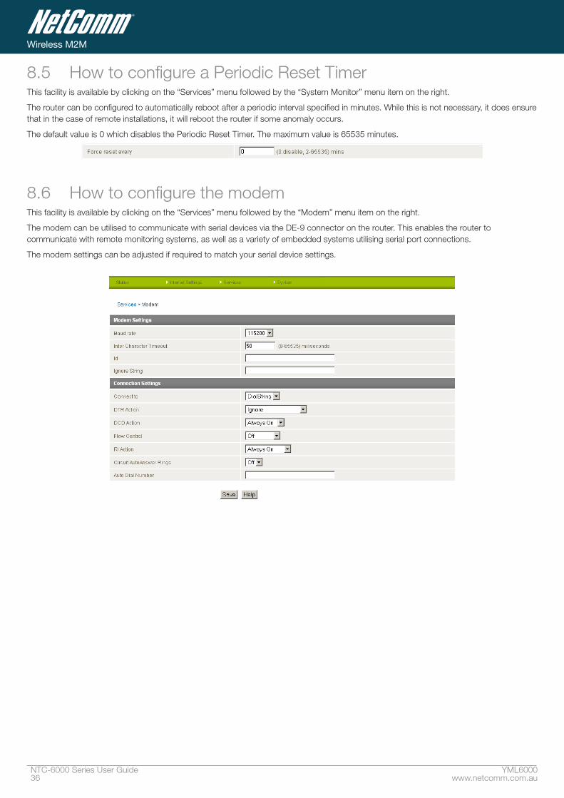
8.5 How to configure a Periodic Reset TimerThis facility is available by clicking on the “Services” menu followed by the “System Monitor” menu item on the right.
The router can be configured to automatically reboot after a periodic interval specified in minutes. While this is not necessary, it does ensure that in the case of remote installations, it will reboot the router if some anomaly occurs.
The default value is 0 which disables the Periodic Reset Timer. The maximum value is 65535 minutes.
8.6 How to configure the modemThis facility is available by clicking on the “Services” menu followed by the “Modem” menu item on the right.
The modem can be utilised to communicate with serial devices via the DE-9 connector on the router. This enables the router to communicate with remote monitoring systems, as well as a variety of embedded systems utilising serial port connections.
The modem settings can be adjusted if required to match your serial device settings.
YML6000 NTC-6000 User Guidewww.netcomm.com.au 37
NetComm CallDirect™ Series - NTC-6000 Series
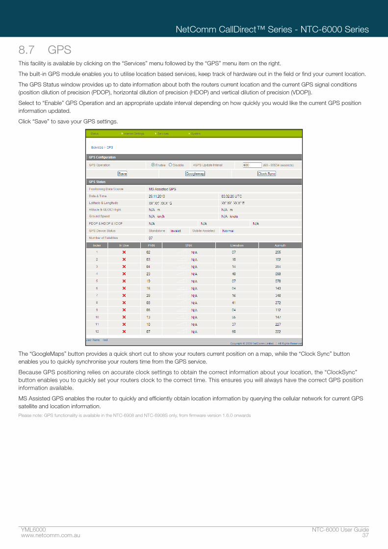
8.7 GPSThis facility is available by clicking on the “Services” menu followed by the “GPS” menu item on the right.
The built-in GPS module enables you to utilise location based services, keep track of hardware out in the field or find your current location.
The GPS Status window provides up to date information about both the routers current location and the current GPS signal conditions (position dilution of precision (PDOP), horizontal dilution of precision (HDOP) and vertical dilution of precision (VDOP)).
Select to “Enable” GPS Operation and an appropriate update interval depending on how quickly you would like the current GPS position information updated.
Click “Save” to save your GPS settings.
The “GoogleMaps” button provides a quick short cut to show your routers current position on a map, while the “Clock Sync” button enables you to quickly synchronise your routers time from the GPS service.
Because GPS positioning relies on accurate clock settings to obtain the correct information about your location, the “ClockSync” button enables you to quickly set your routers clock to the correct time. This ensures you will always have the correct GPS position information available.
MS Assisted GPS enables the router to quickly and efficiently obtain location information by querying the cellular network for current GPS satellite and location information.Please note: GPS functionality is available in the NTC-6908 and NTC-6908S only, from firmware version 1.6.0 onwards

SMS Tools
YML6000 NTC-6000 User Guidewww.netcomm.com.au 39
NetComm CallDirect™ Series - NTC-6000 Series
SMS ToolsThe SMS tools application has been developed to include basic SMS functionality such as sending a message, receiving a message and redirecting an incoming message to another destination. You can also utilise this functionality to read and change run-time variables on the router.
Basic functionality supported: Ability to send a text message via a 3G network and store in permanent storage
Ability to receive a text message via a 3G network and store in permanent storage
Ability to forward incoming text messages via a 3G network to another remote destination which may be a TCP/UDP server or other mobile devices.
Ability to read run-time variables from the device (e.g. uptime) and send result to a remote destination which may be a TCP/UDP server or other mobile devices.
Ability to change live configuration on the device (e.g. connection APN)
Ability to execute supported commands (e.g. reboot)

NTC-6000 Series User Guide YML600040 www.netcomm.com.au
Wireless M2M
9.1 SMS Tools SetupGeneral SMS functionality is enabled by default. You can open the Setup page in order to configure additional settings. To do this, click on “Services”, then “SMS” and then “Setup”.
Item Description
Number of Messages/Page: Enter the number of SMS messages to display per page.
Redirect to Mobile: Forward incoming text messages to the remote destination defined.
Redirect to TCP: Forward incoming text messages to the remote TCP destination defined.
TCP Port to redirect: The TCP port on which to connect to the remote destination on.
Redirect to UDP: Forward incoming text messages to the remote UDP destination defined.
UDP Port to redirect: The UDP port on which to connect to the remote destination on.
Enable Remote Diagnostics: Enable diagnostics to be performed by a specially crafted SMS message.
YML6000 NTC-6000 User Guidewww.netcomm.com.au 41
NetComm CallDirect™ Series - NTC-6000 Series
9.2 SMS Configuration for RedirectionIncoming text messages can be redirected to another mobile device and/or a TCP/UDP message server.
Redirect To MobileYou can forward incoming text messages to a different destination number. This destination number can be another mobile phone or 3G router phone number. To disable the feature, simply delete the number in the ‘Redirect To Mobile” field and click the “Save” button.
For Example: If someone sends a text message and Redirect To Mobile is set to “0412345678”, this text message is stored on the router and forwarded to “0412345678” at the same time.
Redirect to TCP & TCP Port, Redirect to UDP & UDP PortYou can also forward incoming text messages to a TCP/UDP based destination. The TCP or UDP server can be any kind of public or private server if the server accepts incoming text-base message.
The TCP/UDP address can be an IP address or domain name. The port number range is from 1 to 65535. Please refer to your TCP/UDP based SMS server configuration for which port to use.
For Example: If someone sends a text message and Redirect To TCP is set to “192.168.20.3” and “2002”, this text message is stored in the router and forwarded to “192.168.20.3” on port “2002” at the same time.
9.3 SMS Configuration for Remote DiagnosticsEnable Remote DiagnosticsEnable or disable the Remote Diagnostics feature. If this setting is enabled all incoming text messages are parsed and tested for if they contain Remote Diagnostics commands.
If Remote Diagnostics commands are found, the router executes those commands. This feature is disabled by default.Please note: It is possible to adjust settings and prevent your router from functioning correctly. If this occurs, you will need to perform a factory reset in order to restore
normal operation. It is highly recommended to enable security when utilising this feature.
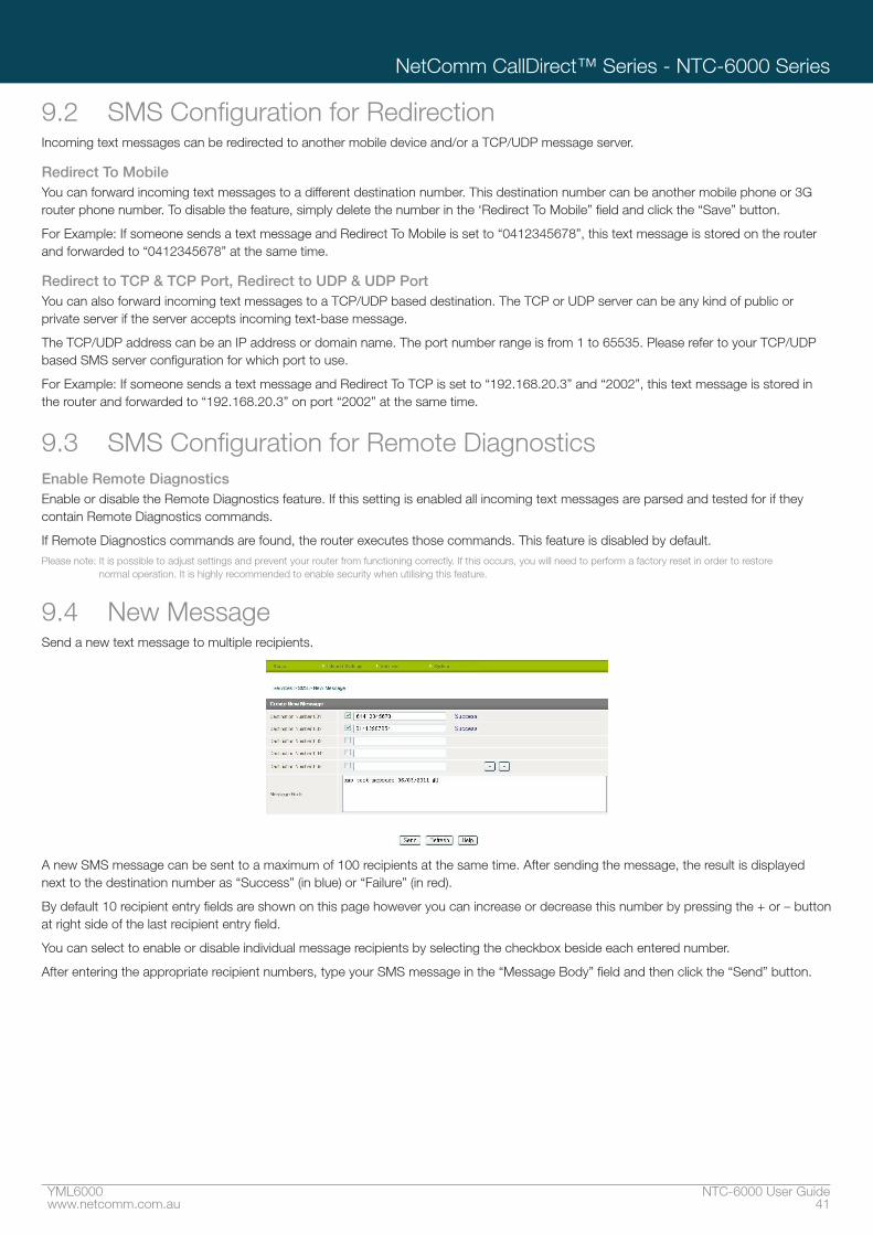
9.4 New MessageSend a new text message to multiple recipients.
A new SMS message can be sent to a maximum of 100 recipients at the same time. After sending the message, the result is displayed next to the destination number as “Success” (in blue) or “Failure” (in red).
By default 10 recipient entry fields are shown on this page however you can increase or decrease this number by pressing the + or – button at right side of the last recipient entry field.
You can select to enable or disable individual message recipients by selecting the checkbox beside each entered number.
After entering the appropriate recipient numbers, type your SMS message in the “Message Body” field and then click the “Send” button.

NTC-6000 Series User Guide YML600042 www.netcomm.com.au
Wireless M2M
9.5 Inbox/OutboxYou can check all sent SMS messages in the SMS Outbox or you can read, delete, reply or forward an SMS message to another mobile device from the SMS Inbox.
You are also able to add the SMS message sender to the “White List” which is used to secure the Remote Diagnostics feature. Simply select the sender or recipient number and click the “Add White List” button.
9.6 Diagnostics and Command Execution Setup
Enable AuthenticationEnable or disable checking the sender’s phone number against the allowed sender “White List” for incoming Diagnostics/Command Execution SMS messages.
If authentication is enabled, the router will check if the sender’s number exists in the “White List”. If it exists, the router then checks the password in the incoming message against the password in the “White List” for the corresponding sending number. If they match, the Diagnostics/Command is executed.
If the number does not exist in “White List” or the password does not match, the router does not execute the incoming Diagnostics/Command Execution SMS message.
This is enabled by default.
It is highly recommended to enable security when utilising the Diagnostics/Command Execution feature.
YML6000 NTC-6000 User Guidewww.netcomm.com.au 43
NetComm CallDirect™ Series - NTC-6000 Series
Send Ack� SMS for Set CommandEnable or disable sending an acknowledge message after execution of a “Set” command.
If disabled the router does not send any acknowledgement after execution of a “Set” command. This can be useful to determine if a command was received and executed by the router. This is disabled by default.
Send Ack� SMS toSelect destination to send an acknowledgement message to after the execution of a “Set” command.
If “Fixed Ack. SMS Number” is selected, the acknowledgement message will be sent to the predefined number in the “Fixed Ack. SMS Number” field.
If the SMS Sender Number is selected, the acknowledgement message will be sent to sender directly. The default setting is to use “SMS Sender Number”.
Fixed Ack� SMS NumberThe destination number to which acknowledgement messages are sent after the execution of a “Set” command.
Send Error SMS for Get/Set/Exec CommandEnable or disable the sending of an error message resulting from the execution of a Get/Set/Exec command.
If disabled, the router does not send any error notifications after the execution of a Get/Set/Exec command.
This function is disabled by default.
Send Error SMS toSelect the destination of the error messages from the execution of a Get/Set/Exec command.
If “Fixed Number” is selected, any error messages will be sent to the predefined number in the “Fixed Error SMS Number” field.
If “SMS Sender Number” is selected, any error messages will be sent to the sender directly.
The default setting is to use “SMS Sender Number”.
Fixed Error SMS NumberThe destination number to which error messages from the execution of a Get/Set/Exec command should be sent.
Max� Diag� SMS Tx LimitYou can set the maximum number of acknowledgement and error messages sent when an SMS Diagnostics and/or Command is executed. You can set the maximum limit on a per hour/day/week or month basis.
The default is to send a maximum of 100 messages per day.
You can check the current sent message count by looking next to the “Max. Diag. SMS Tx Limit” field. If the maximum number has been exceeded, you can also reset sent the message counter by pressing the “Reset” button.
The Total transmitted message count resets after a reboot or at the beginning of the time frame specified. Please note: Times displayed are in UTC format.
For example:
If the time frame is set to “HOUR” and the current time is “04:30”, then the counter will reset to zero at “05:00”.
If time frame is set to “DAY” and current date and time is “04:30” 17th of March, then the counter will reset to zero at “00:00” 18th of March.
If time period is set to “WEEK” and current date and time is “04:30” Saturday, then the counter will reset to zero at “00:00” on the coming Monday.
If time period is set to “MONTH” and current date and time is “04:30” 17th of March, then the counter will reset to zero at “00:00” 1st of April.

NTC-6000 Series User Guide YML600044 www.netcomm.com.au
Wireless M2M
White ListA maximum number of 20 entries can be stored in the router.
If Authentication is enabled, any incoming Diagnostics/Command Execution SMS messages are processed only if the sender’s number exists in White List and the message password matches with the password specified in the White List.
One blank entry is shown by default and you can add or delete an entry by pressing the “+” or ”–“ button. The White List numbers and passwords can be cleared by pressing the “Delete” button.
To add an entry, simply enter the appropriate phone number and password and click “Save”.
Message Storage for Diagnostic MessagesDiagnostic messages (Diagnostic commands, acknowledgements and error notification messages) sent to remote destination are stored in Inbox/Outbox.
9.7 SecurityIn order to provide security for SMS command execution, it is recommended that all SMS commands be subject to successful authentication against the White List as well as setting a password for each phone number entered.
This prevents unauthorised or accidental execution of SMS commands.
9.8 SMS Command formatGeneric Format for reading variables:
get VARIABLENAME
PASSWORD get VARIABLENAME
Generic Format for writing to variables:
set VARIABLENAME=VALUE
PASSWORD set VARIABLENAME=VALUE
Generic Format for executing a command:
execute COMMAND
PASSWORD execute COMMAND
9.9 RepliesUpon receipt of successfully formatted, authenticated (if required) command, the router will reply to the SMS in the following format:
Type SMS Contents Notes
Get Command “VARIABLENAME=VALUE”
Set Command “Successfully set VARIABLENAME to VALUE” Only sent if the acknlowedgment message
function is enabled
Execute Command “Successfully executed command COMMAND”
Where “VARIABLENAME” is the name of the value to be read
Where “VARIABLENAME(x)” is the name of another value to be read
Where “VALUE” is the content to be written to the “VARIABLENAME”
Where “COMMAND” is a supported command to be executed by the device (e.g reboot)
Where “PASSWORD” is the password (if configured) for the corresponding sender number specified in the White List
Multiple commands can be sent in the same message, if separated by a semicolon.
For Example:
get VARIABLENAME1; get VARIABLENAME2; get VARIABLENAME3
PASSWORD get VARIABLENAME1; get VARIABLENAME2
set VARIABLENAME=VALUE1 ; set VARIABLENAME2=VALUE2
PASSWORD set VARIABLENAME1=VALUE1; set VARIABLENAME2=VALUE2; set VARIABLENAME3=VALUE3
If required, values can also be bound by an apostrophe, double apostrophe or back tick.
For Example:
“set VARIABLE=’VALUE’”
“set VARIABLE=”VALUE””

YML6000 NTC-6000 User Guidewww.netcomm.com.au 45
NetComm CallDirect™ Series - NTC-6000 Series
“set VARIABLE=`VALUE`”
“get VARIABLE”
A password (if required), only needs to be specified once per SMS, but can be prefixed to each command if desired.
“PASSWORD get Variable1”; “get VARABLE2”
“PASSWORD set VARIABLE1=VALUE1”; “set VARIABLE2=VALUE2”
If the command sent includes the “reboot” command and has already passed the White List password check, the device keeps this password and executes the remaining command line after the reboot with this same password.
For Example:
“PASSWORD execute reboot; get Variable1”; “get VARABLE2”
“PASSWORD execute reboot; PASSWORD get Variable1”; “get VARABLE2”
Commands are case insensitive, however variable names and values are case sensitive
9.10 List of valid commands (which can be used in conjunction with the execute command):
“pdpcycle”, “pdpdown” and “pdpup” commands can have a profile number suffix ‘x’ added. Without the suffix specified, the command operates against the current active profile or last active profile.
# Command name Description
1 reboot Immediately perform a soft reboot
2 pdpcycle or pdpcyclex Disconnect (if connected) and reconnect the 3G connection. If a profile number is selected in the command,
try to disconnect/reconnect the specified profile in case the profile is active. If no profile number is selected, try
to disconnect/reconnect the current active profile. Reports an error if no profile number is selected and there
is no currently activated profile.
3 pdpdown or pdpdownx Disconnect the PDP. If a profile number is selected in the command, try to disconnect the specified profile in
case the profile is active. If no profile number is selected, try to disconnect the current active profile. Reports
an error if no profile number is selected and there is no currently activated profile.
4 pdpup or pdpupx Reconnect the PDP. If a profile number is selected in the command, try to connect with the specified profile.
If no profile number is selected, try to connect to the last active profile. The router will check the currently
activated profile and disconnect this profile before executing the command. Reports an error if no profile
number is selected and there is no stored last active profile number.
9.11 List of valid variables:Where “x” is a profile number (1-6). If no profile is specified, variables are read or written to for the current active profile. If a profile is specified, variable are read or written to for the specified profile number (‘x’).
# RDB variable name SMS variable name Read/Write Description Example
0 link.profile.x.enable
link.profile.x.apn
link.profile.x.user
link.profile.x.pass
link.profile.x.auth_type
link.profile.x.iplocal
link.profile.x.status
profile or profilex RW Profile Read: (profile no,apn,user,pass,auth,iplocal,status)
1,Telstra.internet,username,password, chap,202.44.185.111,up
Write: (apn, user, pass,auth)
Telstra.internet,username,password
1 link.profile.x.apn apn or apnx RW APN telstra.internet
2 link.profile.x.user username or usernamex RW 3G username Guest, could also return “null”
3 link.profile.x.pass password or password RW 3G password Guest, could also return “null”
4 link.profile.x.auth_type authtype or authtypex RW 3G Authentication type ”pap” or”chap”
5 link.profile.x.iplocal wanip or wanipx R WAN IP address 202.44.185.111
6 wwan.0.radio.information.
signal_strength
rssi R 3G signal strength 65 dBm
7 wwan.0.imei imei R IMEI number 359102128941027512
8 statistics.usage_current usage R 3G data usage of current session “Rx 500 bytes, Tx 1024 bytes, Total 1524 bytes” or “Rx 0
byte, Tx 0 byte, Total 0 byte” when wwan down
9 statistics.usage_current wanuptime R Up time of current 3G session 1 days 02:30:12 or 0 days 00:00:00 when wwan down
10 /proc/uptime deviceuptime R Device up time 1 days 02:30:12
11 wwan.0.system_network_
status.current_band
band R Current 3G frequency WCDMA 850

NTC-6000 Series User Guide YML600046 www.netcomm.com.au
Wireless M2M
9.12 SMS Diagnostics ExamplesThe examples below demonstrate various combinations of supported commands.
Description Authentication Input Example
Send SMS to change APN Not required set apn1=Telstra.internet
set apn2=”3netaccecss”
Required Password1234 set apn1=Telstra.internet
Password1234 set apn2=3netaccecss
Send SMS to change the 3G username Not required set username=’NetComm’
Required Password1234 set username= ”NetComm”
Send SMS to change the 3G password Not required set password= `NetComm`
Required Password1234 set password= `NetComm`
Send SMS to change the 3G authentication Not required set authtype= ‘pap’
Required Password1234 set authtype = pap
Send SMS to reboot Not required execute reboot
Required Password1234 execute reboot
Send SMS to check the WAN IP address Not required get wanip
Required Password1234 get wanip
Send SMS to check the 3G signal strength Not required get rssi
Required Password1234 get rssi
Send SMS to check the IMEI number Not required get imei
Required Password1234 get imei
Send SMS to check the current band Not required get band
Required Password1234 get band
Send SMS to Disconnect (if disconnected) and
reconnect the 3G connection
Not required execute pdpcycle
Required Password1234 execute “pdpcycle1”
Send SMS to disconnect the 3G connection Not required exceute pdpdown1
Required Password1234 execute “pdpdown1”
Send SMS to connection the 3G connection Not required execute pdpup
Required Password1234 execute pdpup1
Send multiple get command Not required get wanip; get rssi
Required Password1234 get wanip; get rssi
Send multiple set command Not required set apn1=”3netaccecss”; set password1=’NetComm’
Required Password1234 set apn=”3netaccecss”; set
password=NetComm

System Features

NTC-6000 Series User Guide YML600048 www.netcomm.com.au
Wireless M2M
System Features 10.1 Remote administrationThis facility is available by clicking on the “System” menu followed by “Administration“.
Once Remote administration is enabled, you are able to access the router’s web-based configuration pages from a remote location to make configuration changes and to enable or disable features.
To get remote access, you have to connect to the WAN IP address of the router on the port assigned in the configuration page (e.g. 8080) after a connection to the cellular network via a data connection has been established.
To configure Remote Administration follow the steps below:
Click “Enable” to activate Remote Administration
Change the Remote Administration Port number if required; the factory default is 8080.
You may change the remote access password for enhanced security.
Click “Save”
Note: The password will only be changed if you enter two matching passwords. It is not necessary to change the password if you are only changing the incoming port number.
The WAN IP address below is an example only, yours will be different.
http://10�10�10�10:8080
Username admin
Password admin
http://10�10�10�10:8090
Username root
Password admin
Below illustrates the steps required to access the router’s configuration pages remotely from a remote computer:
1. Open a new browser window (e.g. Internet Explorer, Firefox, Safari ...).
2. In the address bar, enter the router’s WAN IP address and assigned port number, e.g. “10.10.10.10: 8080”.Note: You can find the router’s WAN IP address by clicking on the ”Status” menu. The Local field in the WWAN section shows the router’s WAN IP address.
3. Click “Login” and type “admin” or “root” in the Username and “admin” in the Password fields (without quotes). Then click on “Submit”.
Note: To perform functions like Firmware upgrade, device configuration backup and to restore and reset the router to factory defaults, you need to login as the root user.
YML6000 NTC-6000 User Guidewww.netcomm.com.au 49
NetComm CallDirect™ Series - NTC-6000 Series
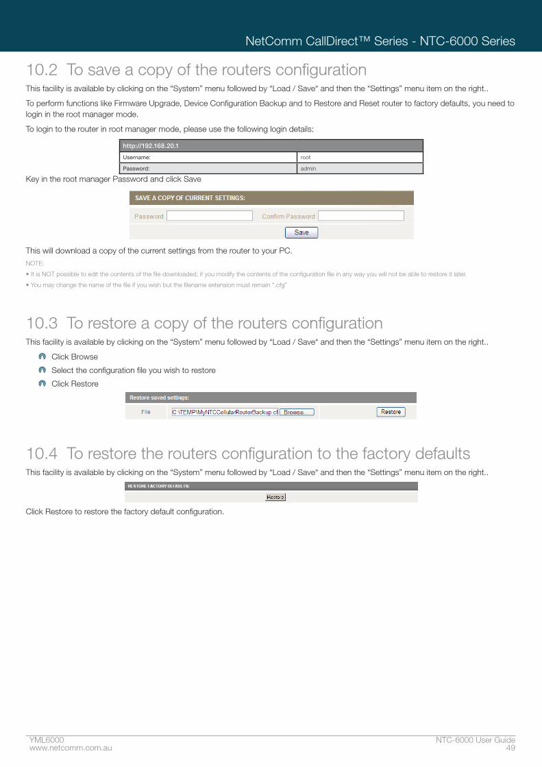
10.2 To save a copy of the routers configurationThis facility is available by clicking on the “System” menu followed by “Load / Save“ and then the “Settings” menu item on the right..
To perform functions like Firmware Upgrade, Device Configuration Backup and to Restore and Reset router to factory defaults, you need to login in the root manager mode.
To login to the router in root manager mode, please use the following login details:
http://192�168�20�1
Username: root
Password: admin
Key in the root manager Password and click Save
This will download a copy of the current settings from the router to your PC.NOTE:
• It is NOT possible to edit the contents of the file downloaded; if you modify the contents of the configuration file in any way you will not be able to restore it later.
• You may change the name of the file if you wish but the filename extension must remain “.cfg”
10.3 To restore a copy of the routers configurationThis facility is available by clicking on the “System” menu followed by “Load / Save“ and then the “Settings” menu item on the right..
Click Browse
Select the configuration file you wish to restore
Click Restore
10.4 To restore the routers configuration to the factory defaultsThis facility is available by clicking on the “System” menu followed by “Load / Save“ and then the “Settings” menu item on the right..
Click Restore to restore the factory default configuration.

NTC-6000 Series User Guide YML600050 www.netcomm.com.au
Wireless M2M
10.5 To upgrade the router’s system or recovery console software versionThis facility is available by clicking on the “System” menu followed by “Load / Save” and then the “Upload” menu item on the right. The firmware of the router can be updated locally via LAN connection and also via remote access. Both upgrade types follow a similar process.
To update the firmware of the embedded cellular WAN module please consult the module upgrade manual available with the respective upgrade files on our website (www.netcomm-commercial.com.au), in the support section.Note: In order to perform an update, you must be logged into the router as the root user (see chapter 9.1 Remote Administration for more details).
10.5.1 Local firmware upgradeThe firmware update process has two steps. The first step is to upload and install the system recovery image onto the router.
You can do this by clicking on the browse button and then to navigate to where the recovery image upgrade file is located on your computer
Once you have selected the system recovery image file to use, click Upload to upload the file. You will then see a progress bar as shown in the screenshot below. The upload has finished when the status bar reaches 100% and the “Phase:” has changed to Complete.
When the upload has completed, the screen should refresh and list the system recovery file you have just uploaded. Click on the “Install” link to the right of this.
Once you see “Done” shown as per the screenshot below, you can then boot into the system recovery mode to install the main system software.
Press and hold the reset button for approximately 5 – 10 seconds until the LEDs on the front of the router start to flash in an ON / OFF sequence and then release it. The router will now boot into the system recovery mode.
The second step is to upload and install the main system software. To do this, open your web browser (e.g. Internet Explorer/Firefox/Safari) and navigate to http://192.168.20.1/

YML6000 NTC-6000 User Guidewww.netcomm.com.au 51
NetComm CallDirect™ Series - NTC-6000 Series
Click “Login” and type “root” in the Username and and “admin” in the Password fields (without quotes). Then click on “Submit”. The banner at the top of the page should be different to show that the router is currently in recovery console mode.
To upload the main system software, click on “Application Installer” from the menu at the top of the page and then click on the browse button and navigate to where the main system image upgrade file is located on your computer]
Once you have selected the recovery image file to use, click Upload to upload the file. You will then see a progress bar as shown in the screenshot below. The upload has finished when the status bar reaches 100% and the “Phase:” has changed to Complete.
When the upload has completed, the screen should refresh and list the file you have just uploaded. Click on the “Install” link to the right of this.
Once you see “Done” shown as per the screenshot below, click on “Reboot” at the top of the page and then click the “Reboot” button to restart the router
The router will now start up with the new system software loaded.

NTC-6000 Series User Guide YML600052 www.netcomm.com.au
Wireless M2M
10.5.2 Remote firmware upgradeThe remote firmware update process has two steps:
1. Upload and install the system recovery image to the router
2. Upload and install the main system image to the router.Note: Do not interrupt the power during a remote firmware upgrade, as this may render the router unable to start up and will require a local system recovery upload to be performed.
You can do this by clicking on the browse button and then to navigate to where the recovery image upgrade file is located on your computer
Once you have selected the recovery image file to use, click Upload to upload the file. You will then see a progress bar as shown in the screenshot below. The upload has finished when the status bar reaches 100% and the “Phase:” has changed to Complete.
When the upload has completed, the screen should refresh and list the file you have just uploaded. Click on the “Install” link to the right of this.
Once you see “Done” shown as per the screenshot below,
Click on the browse button again and navigate to where the main system image upgrade file is located on your computer

Troubleshooting

NTC-6000 Series User Guide YML600054 www.netcomm.com.au
Wireless M2M
Once you have selected the main system image file to use, click Upload to upload the file. You will then see a progress bar as shown in the screenshot below. The upload has finished when the status bar reaches 100% and the “Phase:” has changed to Complete.
When the upload has completed, the screen should refresh and list the file you have just uploaded. Click on the “Install” link to the right of this.
Once the install has completed, the router will automatically reboot, install the new main system image and then start up and reconnect to your selected Internet service. Note: This process can take up to 10 minutes.

YML6000 NTC-6000 User Guidewww.netcomm.com.au 55
NetComm CallDirect™ Series - NTC-6000 Series
11 Troubleshooting11.1 Viewing the system logThis facility is available by clicking on the “System” menu followed by “Log“..
The System Log enables you to troubleshoot any issues you may be experiencing with your router.
Selecting the appropriate logging level will show you either informational messages about your router or every message produced when “All” is selected.
11.2 Common problems and solutions.11�2�1 I cannot seem to access the web page interfaceThe default IP address of the router is 192.168.20.1, so first try to open a web browser to this address. Also check that your laptop/PC is on the same subnet as the router’s Ethernet port if you are using a static IP address.
11�2�2 The router was connected but cannot get back online�You may need to enable the periodic ping timer using the System Monitor (Click on the “Services” menu followed by “System Monitor”).
This ensures that if the connection drops (i.e outage on the network), that the router will reboot after so many failed pings and then force a re-connect. Setting the timer to around 15 mins should be sufficient.NOTE: The traffic generated by the periodic ping feature is counted as chargeable usage, please keep this in mind when selecting how often to ping.
11�2�3 The router is rebooting frequentlyCheck the “System Monitor” configuration and see if the ”force reset every” option is set to something other than 0.
If it is set to 1 this means the unit will reboot every minute regardless of what happens.
Reset it to 0 if you don’t want this feature or something quite large if you don’t want the router to reboot so often.
11�2�4 The router has a connection but cannot access the internetCheck that DNS Masquerade is enabled by clicking on the “Internet Settings” menu followed by “LAN“ and then the “IP Setup” menu item on the right..
Make sure that the DHCP DNS server address is set to the same address as that of the Ethernet port.

Specifications

YML6000 NTC-6000 User Guidewww.netcomm.com.au 57
NetComm CallDirect™ Series - NTC-6000 Series
11�2�5 I cannot seem to get a cellular WAN connection Click on the “Internet Settings” menu followed by “WWAN (3G)“ and then the “Connection” menu item on the right and check that
the APN is correct.
Also check that the username and password credentials are correct if the APN in use requires these.
Make sure that Auto Connect is enabled..
11�2�6 I have set the Band but now it does not show the correct Frequency on the Status page and I cannot get a connectionIf this happens you must reboot the router.
11�2�7 The SIM status indicates “SIM removed” on the status pageIf a SIM was installed correctly this may indicate that the SIM has been removed or inserted whilst the unit is powered up. In this case you must reboot the unit.
To reboot the router, click on the “System” menu followed by “Reboot“. Clicking the reboot button on this page will reboot the router.
11�2�8 I am having problems getting a PPTP connection�Check the routes on the “Routing” configuration page (This facility is available by clicking on the “Internet Settings” menu followed by “Routing“ and then the “Static Route” menu item on the right.)
There should be 5 routes shown.
One route for interface eth0.
Two routes for interface ppp0.
Two routes for interface ppp1.
If there are not 5 routes, it is possible the one of the following conditions exist:
PPTP is not enabled.
The credentials on the PPTP Configuration page are incorrect (IP address / Username / Password).
If you see the message: “The synchronous PPTP option is not activated” or “CHAP Authentication Failure”, then the credentials are incorrect.

NTC-6000 Series User Guide YML600058 www.netcomm.com.au
Wireless M2M
Specifications 12.1 Hardware specifications
NTC-6908 NTC-6909
MCU / Processor Atmel AT91SAM9G20 Microcontroller / ARM9 based
RAM 32MB DRAM
Memory 256MB NAND Flash
Wireless WAN Interface Sierra Wireless MC8790V Sierra Wireless MC8792V
Chipset Qualcomm MSM6290
3G UMTS Bands 850/ 1900/ 2100 MHz 900/ 1900/ 2100 MHz
2G GSM Bands 850/ 900/ 1800/ 1900 MHz
Peak Data Speed HSDPA Category 8 – Downlink up to 7.2 Mbps
HSUPA Release 6 – Uplink up to 5.76 Mbps
EDGE Multi Slot Class 12 – Downlink/Uplink up to 236 kbps
SIM Card Reader Locking Tray for SIM/SIM in Mini-SIM card format (25.00 x 15.00 x 0.76 mm)
Antenna Interface 2x SMA (female), 50 Ohm
Network Interfaces 1x Fast Ethernet 10/100Base-TX RJ-45 port with Auto MDI/MDIX
1x Serial RS-232 DE-9 female DCE port
LED Indicators 5x LEDs: Power, Service, Tx/Rx, DCD, RSSI
Power Input Captive DECA® Euro Type Terminal Block MC100#50802 (DC Plug with Screw Terminal)
Input Voltage Range 8 - 28 VDC
Power Consumption Idle: 1.44W (120 mA @ 12 V DC)
Active HSUPA connection: 2.16W (180 mA @ 12 V DC)
Dimensions 127 x 103 x 29 mm
Weight 240g
Temperature / Humidity Operating: -30°C ~ 70°C (-22 ~ 140 F) / 0 ~ 85% (non-condensing)
Storage: -55°C ~ 85°C (-67 ~ 185 F) /
Regulatory Compliancy A-Tick, RoHS
12.2 RJ-45 Ethernet port integration parametersYou can use the guide below to design Ethernet cables to integrate the router into your systems. Below you will find pin outs of the RJ-45 Ethernet Plug and Jack connectors:
Pin Function Color
1 TX + White/Orange
2 TX - Orange/White
3 RX + White/Green
4 Blue/White
5 White/Blue
6 RX - Green/White
7 White/Brown
8 Brown/White
NOTE: The Ethernet port on the router supports Auto MDI/MDIX, you may use a straight through or cross-over Ethernet cable.

YML6000 NTC-6000 User Guidewww.netcomm.com.au 59
NetComm CallDirect™ Series - NTC-6000 Series
12.3 RS-232 serial port integration parametersYou can use the table below to design serial cables to integrate the router into your system.
Standard RS-232 DE-9 Pinout:
Pin Name Direction Description
1 CD —» Carrier Detect
2 RX —» Receive Data
3 TX «— Transmit Data
4 DTR «— Data Terminal Ready
5 GND System Ground
6 DSR —» Data Set Ready
7 RTS «— Request to Send
8 CTS —» Clear to Send
9 RI —» Ring Indicator
Note:
—» Output from router
«— Input to router
Shown below are the communications parameters of the RS-232 port:
Default RS-232 Communication Parameters:
Bits Per Second: 115,200
Data Bits: 8
Parity: None
Stop Bits: 1
Flow Control: Hardware
12.4 Custom Application and ScriptingThe NTC series router covered in this manual offers the ability for the user to install custom application / firmware images via the application programming interface.
For further information, please contact the NetComm 3G Mobile Broadband Solution support team.
Phone: (02) 9424 2053
Fax: 1800 063 962
Email: service@call-direct com.au
Web www.netcom-commercial.com.au

Appendix

YML6000 NTC-6000 User Guidewww.netcomm.com.au 61
NetComm CallDirect™ Series - NTC-6000 Series
Legal & Regulatory InformationLimitation of LiabilityNetComm Limited reserves the right to change the specifications and operating details of this product without notice. The information in this document does not represent a commitment on the part of NetComm Limited.
To the fullest extent permitted by law NetComm Limited and its affiliates disclaim liability for any and all direct, indirect, special, general, incidental, consequential, punitive or exemplary damages including, but not limited to , loss of profits or revenue or anticipated profits or revenue arising out of the use or inability to use any NetComm product, even if NetComm Limited and/or its affiliates has been advised of the possibility of such damages or they are foreseeable or for claims by any third party.
Notwithstanding the foregoing, in no event shall NetComm Limited and/or its affiliates aggregate liability arising under or in connection with the NetComm product, regardless of the number of events, occurrences, or claims giving rise to liability, be in excess of the price paid by the purchaser for the NetComm product.
Where the NetComm product supplied is not of a kind ordinarily acquired for personal, domestic or household use or consumption, NetComm Limited and its affiliates limit their liability to, at their option, the replacement or repair of the NetComm product or the payment of the cost of replacement or repair of the NetComm product.
Nothing in this clause excludes, restricts or modifies any condition, warranty, guarantee, right or remedy under a mandatory law.
CopyrightThis manual is copyright. Apart from any fair dealing for the purposes of private study, research, criticism or review, as permitted under
the Copyright Act, no part may be reproduced, stored in a retrieval system or transmitted in any form, by any means, be it electronic, mechanical, recording or otherwise, without the prior written permission of NetComm Limited. NetComm Limited accepts no liability or responsibility, for consequences arising from the use of this product.
TrademarksNetComm, the NetComm logo and NetComm CallDirect™ are trademarks of NetComm Limited. Sierra Wireless is trademark of Sierra Wireless. Windows® is a registered trademark of Microsoft Corporation.
All other trademarks are acknowledged the property of their respective owners.
Regulatory Information (Australia)ACA (Australian Communications Authority) requires you to be aware of the following information and warnings:
(1) This unit shall be connected to the Telecommunication Network through a line cord which meets the requirements of the ACA TS008 Standard.
(2) This equipment has been tested and found to comply with the Standards for C-Tick and or A-Tick as set by the ACA.
These standards are designed to provide reasonable protection against harmful interference in a residential installation. This equipment generates, uses, and can radiate radio noise and, if not installed and used in accordance with the instructions detailed within this manual, may cause interference to radio communications. However, there is no guarantee that interference will not occur with the installation of this product in your home or office. If this equipment does cause some degree of interference to radio or television reception, which can be determined by turning the equipment off and on, we encourage the user to try to correct the interference by one or more of the following measures:
• Change the direction or relocate the receiving antenna.
• Increase the separation between this equipment and the receiver.
• Connect the equipment to an alternate power outlet on a different power circuit from that to which the receiver/TV is connected.
• Consult an experienced radio/TV technician for help.
(3) The power supply that is provided with this unit is only intended for use with this product. Do not use this power supply with any other product or do not use any other power supply that is not approved for use with this product by NetComm. Failure to do so may cause damage to this product, fire or result in personal injury.

NTC-6000 Series User Guide YML600062 www.netcomm.com.au
Wireless M2M
GNU General Public LicenseThis product includes software code that is subject to the GNU General Public License (“GPL”) or GNU Lesser General Public License
(“LGPL”). This code is subject to the copyrights of one or more authors and is distributed without any warranty. A copy of this software can be obtained by contacting NetComm Limited on +61 2 9424 2059.
Product WarrantyThe warranty is granted on the following conditions:
1. This warranty extends to the original purchaser (you) and is not transferable;
2. This warranty shall not apply to software programs, batteries, power supplies, cables or other accessories supplied in or with the product;
3. The customer complies with all of the terms of any relevant agreement with NetComm and any other reasonable requirements of NetComm including producing such evidence of purchase as NetComm may require;
4. The cost of transporting product to and from NetComm’s nominated premises is your responsibility; and,
5. NetComm does not have any liability or responsibility under this warranty where any cost, loss, injury or damage of any kind, whether direct, indirect, consequential, incidental or otherwise arises out of events beyond NetComm’s reasonable control. This includes but is not limited to: acts of God, war, riot, embargoes, acts of civil or military authorities, fire, floods, electricity outages, lightning, power surges, or shortages of materials or labour.
6. The customer is responsible for the security of their computer and network at all times. Security features may be disabled within the factory default settings. NetComm recommends that you enable these features to enhance your security.
The warranty is automatically voided if:
1. You, or someone else, use the product, or attempts to use it, other than as specified by NetComm;
2. The fault or defect in your product is the result of a voltage surge subjected to the product either by the way of power supply or communication line, whether caused by thunderstorm activity or any other cause(s);
3. The fault is the result of accidental damage or damage in transit, including but not limited to liquid spillage;
4. Your product has been used for any purposes other than that for which it is sold, or in any way other than in strict accordance with the user manual supplied;
5. Your product has been repaired or modified or attempted to be repaired or modified, other than by a qualified person at a service centre authorised by NetComm; and,
6. The serial number has been defaced or altered in any way or if the serial number plate has been removed.
Limitations of WarrantyThe Trade Practices Act 1974 and corresponding State and Territory Fair Trading Acts or legalisation of another Government (“the relevant acts”) in certain circumstances imply mandatory conditions and warranties which cannot be excluded. This warranty is in addition to and not in replacement for such conditions and warranties.
To the extent permitted by the Relevant Acts, in relation to your product and any other materials provided with the product (“the Goods”)
the liability of NetComm under the Relevant Acts is limited at the option of NetComm to:
• Replacement of the Goods; or
• Repair of the Goods; or
• Payment of the cost of replacing the Goods; or
• Payment of the cost of having the Goods repaired.
All NetComm ACN 002 490 486 products have a standard 12 months warranty from date of purchase. However some products have an extended warranty option (refer to packaging). To be eligible for the extended warranty you must supply the requested warranty information to NetComm within 30 days of the original purchase by registering on-line via the NetComm web site atwww�netcomm-commercial�com�au

NetComm CallDirect™ Series - NTC-6000 Series
DYNALINK NZ 12c Tea Kea Place, Albany, Auckland, New Zealand P: 09 448 5548 F: 09 448 5549E: [email protected] W: www.dynalink.co.nz
Trademarks and registered trademarks are the property of NetComm Limited or their respective owners. Specifications are subject to change without notice. Images shown may vary slightly from the actual product.
NETCOMM LIMITED Head Office PO Box 1200, Lane Cove NSW 2066 AustraliaP: 02 9424 2070 F: 02 9424 2010 E: [email protected] W: www.netcommlimited.com.