Industrial Gear Units of the M.. Series M.PV../M.RV ...facilitate the assignment of components to...
104
Gearmotors \ Industrial Gear Units \ Drive Electronics \ Drive Automation \ Services Industrial Gear Units of the M.. Series M.PV../M.RV.. Vertical Gear Units O perating Instructions D6.C00 Edition 08/2004 11280816 / EN
Transcript of Industrial Gear Units of the M.. Series M.PV../M.RV ...facilitate the assignment of components to...

Gearmotors \ Industrial Gear Units \ Drive Electronics \ Drive Automation \ Services
Industrial Gear Units of the M.. SeriesM.PV../M.RV.. Vertical Gear Units
Operating Instructions
D6.C00
Edition 08/200411280816 / EN

SEW-EURODRIVE – Driving the world

Contents
Operating Instructions - Industrial Gear Units of the M.. Series Vertical Gear Units M.PV../M.RV.. 3
1 Important Notes................................................................................................. 4
2 Safety Notes ...................................................................................................... 52.1 Transport of industrial gear units .............................................................. 62.2 Corrosion protection and storage conditions ............................................ 7
3 Gear Unit Design ............................................................................................... 93.1 Basic design of the M.PV.. series ............................................................. 93.2 Basic design of the M.RV.. series ........................................................... 103.3 Unit designation / nameplates................................................................. 113.4 Mounting positions, shaft positions and directions of rotation................. 133.5 Lubrication of industrial gear units .......................................................... 19
4 Mechanical Installation................................................................................... 224.1 Required tools / resources ...................................................................... 224.2 Before you begin..................................................................................... 224.3 Preliminary work ..................................................................................... 224.4 Gear unit foundation ............................................................................... 234.5 Mounting of solid shaft gear units ........................................................... 284.6 Mounting / removing hollow shaft gear units with keyed connection ...... 304.7 Mounting / removing hollow shaft gear units with shrink disc ................. 334.8 Mounting a motor with motor adapter ..................................................... 38
5 Mechanical Installation Options .................................................................... 395.1 Important installation instructions............................................................ 395.2 Mounting of couplings ............................................................................. 425.3 Oil heater ................................................................................................ 505.4 Temperature sensor PT100 .................................................................... 555.5 SPM adapter ........................................................................................... 565.6 Fan.......................................................................................................... 58
6 Pressure Lubrication ...................................................................................... 596.1 Shaft end pump ...................................................................................... 596.2 Motor pump ............................................................................................ 616.3 External cooling system .......................................................................... 616.4 Customer supplied external cooling and lubrication systems ................. 62
7 Startup.............................................................................................................. 667.1 Startup of M gear units............................................................................ 667.2 Startup of M gear units with backstop..................................................... 677.3 Startup of M gear units with steel oil expansion tanks ............................ 677.4 Taking M gear units out of operation ...................................................... 69
8 Inspection and Maintenance .......................................................................... 708.1 Inspection and maintenance intervals..................................................... 708.2 Lubricant change intervals ...................................................................... 718.3 Inspection and maintenance of the gear unit .......................................... 728.4 Vertical gear units with drywell sealing system on the Low Speed Shaft 75
9 Malfunctions .................................................................................................... 779.1 Gear unit malfunctions ............................................................................ 77
10 Symbols and Mounting Positions ................................................................. 7810.1 Symbols used ......................................................................................... 7810.2 Mounting positions of M.PV.. gear units ................................................. 79
11 Lubricants........................................................................................................ 8311.1 Guideline for oil and grease selection..................................................... 8311.2 Overview of lubricants for M.. industrial gear units ................................. 8711.3 Sealing grease ........................................................................................ 9211.4 Lubricant fill quantities ............................................................................ 93

1
4 Operating Instructions – Industrial Gear Units of the M.. Series Vertical Gear Units M.PV../M.RV..
Important Notes
1 Important NotesSafety and warning instructions
Always follow the safety and warning instructions in this publication!
A requirement of fault-free operation and fulfillment of any rights to claim underguarantee is that you adhere to the information in the operating instructions.Consequently, read the operating instructions before you start working with the gearunit!
The operating instructions contain important information about servicing; as a result,they should be kept in the vicinity of the gear unit.
Waste disposal Follow the current instructions:
• Housing parts, gears, shafts and anti-friction bearings of the gear units must bedisposed of as steel scrap. The same applies to gray cast iron castings unless thereare separate collection arrangements.
• Collect waste oil and dispose of it correctly.
Electrical hazardPossible consequences: Severe or fatal injuries.
Hazard Possible consequences: Severe or fatal injuries.
Hazardous situationPossible consequences: Slight or minor injuries.
Harmful situationPossible consequences: Damage to the drive and the environment.
Important information about explosion protection.
Tips and useful information.
• It is essential to contact SEW-EURODRIVE regarding a subsequent change ofmounting position!
• The industrial gear units of the M.. series are delivered without oil fill. Refer tothe information on the nameplate!
• Refer to the instructions in the sections "Mechanical Installation" and"Startup"!

Operating Instructions – Industrial Gear Units of the M.. Series Vertical Gear Units M.PV../M.RV.. 5
2Safety Notes
2 Safety NotesPreliminary remarks
The following safety notes are concerned with the use of industrial gear units of the M.V..series. If gear units of the R, F, K, S series or motors of the DR/DT/DV series are used,also refer to the safety notes for motors and gear units in the corresponding operatinginstructions.
Also take account of the supplementary safety notes in the individual sections ofthese operating instructions.
General information
During and after operation, industrial gear units and motors have live and moving partsand their surfaces may be hot.
All work related to transport, storage, setting up/mounting, connection, startup,maintenance and repair may only be performed by trained personnel observing
• the corresponding detailed operating instruction(s) and wiring diagrams,
• the warning and safety signs on the industrial gear unit,
• the specific regulations and requirements for the system and
• national/regional regulations governing safety and the prevention of accidents.
Designated use Industrial gear units are intended for industrial systems. They correspond to theapplicable standards and regulations. The technical data and the information aboutpermitted conditions are provided on the nameplate and in the documentation.
It is essential to observe all specified information!
Transport Inspect the delivery for any damage in transit as soon as you receive the delivery.Inform the transport company immediately. It may be necessary to precludestartup.
Startup/operation Check that the direction of rotation is correct in decoupled status (also listen for unusualgrinding noises as the shaft rotates).
Secure the shaft keys for test mode without drive components. Do not render monitoringand protection equipment inoperative even for test mode.
Switch off the main motor if in doubt whenever changes occur in relation to normaloperation (e.g. increased temperature, noise, vibration). Determine the cause; contactSEW-EURODRIVE if necessary.
Inspection / maintenance
Refer to the instructions in Sec. "Inspection and Maintenance".
Severe injuries and damage to property may result from
• incorrect use,
• incorrect installation or operation,
• removal of required protective covers or the housing when this is not permitted.

2
6 Operating Instructions – Industrial Gear Units of the M.. Series Vertical Gear Units M.PV../M.RV..
Transport of industrial gear unitsSafety Notes
2.1 Transport of industrial gear units
Transport eyebolts
Tighten screwed in transport eyebolts [1] firmly. They are only designed for the weightof the industrial gear unit including the motor connected via motor adapter; do not attachany additional loads.
• The main gear unit must only be lifted using lifting ropes or chains on the twoscrewed in transport eyebolts on the main gear unit. The weight of the gear unitis indicated on the nameplate or the dimension sheet. The loads and regula-tions specified on the nameplate must always be observed.
• The length of the lifting chains or ropes must be dimensioned in such a waythat the angle between the chains or ropes does not exceed 45°.
• Eyebolts on the motor, auxiliary gear unit or primary gear unit must not beused for transport (→ following figures)!
• Use suitable, sufficiently rated handling equipment if necessary. Beforestartup, remove securing devices used for transport.
Transport with motor adapter
53749AXXFigure 1: Positions of transport eyebolts
[1]
53374AXXFigure 2: Do not use eyebolts on the motor for transport

Operating Instructions – Industrial Gear Units of the M.. Series Vertical Gear Units M.PV../M.RV.. 7
2Corrosion protection and storage conditionsSafety Notes
2.2 Corrosion protection and storage conditions
Overview Industrial gear units of the M.. series are delivered without oil fill. Observe the corrosionprotection required for the various storage periods listed in the following table:
Standard protection
• The gear unit is delivered on a pallet without cover.
• Protection of the inside of the gear unit: Gear units of the M series undergo a test runwith protection oil.
• Oil seals and seal surfaces are protected through bearing grease.
• SEW-EURODRIVE applies a protective coating to unpainted surfaces, includingspare parts. Before assembly or before other equipment is mounted to suchsurfaces, the protective coating must be removed. To do so, clean the surface withsolvent.
• Small spare parts and loose pieces, such as screws, nuts, etc., are supplied incorrosion protected plastic bags (VCI corrosion protection bag).
• Threaded holes and blind holes are covered by plastic plugs.
• The corrosion protection is not intended for long-term storage or for humidconditions. The operator is responsible for keeping the gear unit in corrosion-freecondition.
• The breather plug (Position → Sec. "Mounting Positions") is delivered in a separatebag and has to be mounted before start-up.
Storage period
Storage conditions
Outdoors, under roof Indoors (dry, warm air, heated if required)
6 months Standard protection Standard protection
12 months Consult with SEW-EURODRIVE Standard protection
24 months Long-term protection Consult with SEW-EURODRIVE
36 months Consult with SEW-EURODRIVE Long-term protection
Sea transport, storage in areas close to the sea Consult with SEW-EURODRIVE Long-term protection

2
8 Operating Instructions – Industrial Gear Units of the M.. Series Vertical Gear Units M.PV../M.RV..
Corrosion protection and storage conditionsSafety Notes
Long-term protection
• The gear unit is packaged in a seaworthy plywood box and is delivered on a palette.This way, the gear unit is protected from humidity and shock. SEW-EURODRIVErecommends a seaworthy package if the gear unit will be stored for an extendedperiod of time or if protection against salty air is required.
• Protection of the inside of the gear unit apart from standard protection: A solvent inthe form of a vapor phase inhibitor (VPI = Vapor Phase Inhibitor) is sprayed throughthe oil filling hole (recommended value: 0.5 liters in a 10 % solvent per m3). Inhibitorsare volatile, fixed substances that saturate the ambient air with their vapor in closedrooms. If the inside of the gear unit is subjected to such an atmosphere, then aninvisible VPI film forms on the components inside the gear unit. This film serves ascorrosion protection. After this protection treatment, the solvent vapors (methanol,ethanol) should have evaporated before closing the gear unit. The breather plug(Position → Sec. "Mounting Positions") is replaced with a screw plug. The breatherplug must be screwed into the gear unit again before startup. Repeat the long-termprotection treatment after 24 or 36 months (→ Overview of corrosion protectionconditions).
• SEW-EURODRIVE applies a protective coating to unpainted surfaces, includingspare parts. Before assembly or before other equipment is mounted to suchsurfaces, the protective coating must be removed. To do so, clean the surface withsolvent.
• Small spare parts and loose pieces, such as screws and nuts are supplied incorrosion protected plastic bags (VCI corrosion protection bag).
• Threaded holes and blind holes are covered by plastic plugs.
• Never open the gear unit near open flames, sparks and hot objects because thesolvent vapors might be ignited.
• Take preventive measures to protect people from solvent vapors. It isabsolutely crucial that open flames are avoided when the solvent is appliedand when the solvent evaporates.
Operating Instructions – Industrial Gear Units of the M.. Series Vertical Gear Units M.PV../M.RV.. 9
3Basic design of the M.PV.. seriesGear Unit Design
3 Gear Unit Design
3.1 Basic design of the M.PV.. series
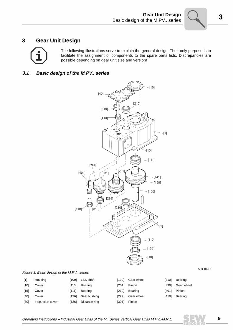
The following illustrations serve to explain the general design. Their only purpose is tofacilitate the assignment of components to the spare parts lists. Discrepancies arepossible depending on gear unit size and version!
53380AXXFigure 3: Basic design of the M.PV.. series
[1] Housing [100] LSS shaft [199] Gear wheel [310] Bearing
[10] Cover [110] Bearing [201] Pinion [399] Gear wheel
[15] Cover [111] Bearing [210] Bearing [401] Pinion
[40] Cover [136] Seal bushing [299] Gear wheel [410] Bearing
[70] Inspection cover [136] Distance ring [301] Pinion
[15]
[40]
[210]
[410]
[310]
[1]
[10]
[111]
[141]
[199]
[100]
[210][310][410]
[401]
[399]
[301][201]
[299]
[1]
[110]
[136]
[10]

3
10 Operating Instructions – Industrial Gear Units of the M.. Series Vertical Gear Units M.PV../M.RV..
Basic design of the M.RV.. seriesGear Unit Design
3.2 Basic design of the M.RV.. series
53727AXXFigure 4: Basic design of the M.RV.. series
[1] Housing [100] LSS shaft [201] Pinion [401] Pinion
[10] Cover [110] Bearing [210] Bearing [410] Bearing
[15] Cover [111] Bearing [299] Gear wheel [449] Bushing
[40] Cover [136] Seal bushing [301] Pinion [499] Bevel wheel
[50] Cover [141] Distance ring [310] Bearing [501] Bevel pinion
[70] Inspection cover [199] Gear wheel [399] Gear wheel [510] Bearing
[511] Bearing
[15]
[40]
[310]
[411]
[210]
[1]
[10]
[111]
[141]
[199]
[100]
[201]
[399]
[299]
[310]
[210]
[410]
[499]
[401]
[110]
[136]
[10]
[1]
[301]
[501]
[510]
[449]
[511]
[80]
[50]

Operating Instructions – Industrial Gear Units of the M.. Series Vertical Gear Units M.PV../M.RV.. 11
3Unit designation / nameplatesGear Unit Design
3.3 Unit designation / nameplates
Sample unit designation
M 3 R V S F 80Size: Vertical 10 ... 90Horizontal 50 ... 90
Gear unit mounting:F = Foot mountingT = Torque arm
Low speed shaft type (LSS):S = Solid shaftH = Hollow shaft (key or shrink disc connection)
Mounting position:no designation: HorizontalV = Vertical
Gear unit type:R = Bevel-helical gear unitP = Helical gear unit
Number of gear stages:2 = Two stages3 = Three stages4 = Four stages
Industrial gear unit series
3
12 Operating Instructions – Industrial Gear Units of the M.. Series Vertical Gear Units M.PV../M.RV..
Unit designation / nameplatesGear Unit Design
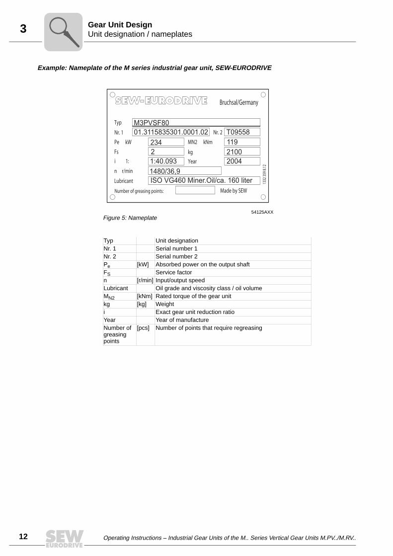
Example: Nameplate of the M series industrial gear unit, SEW-EURODRIVE
54125AXXFigure 5: Nameplate
Typ Unit designationNr. 1 Serial number 1Nr. 2 Serial number 2Pe [kW] Absorbed power on the output shaftFS Service factorn [r/min] Input/output speedLubricant Oil grade and viscosity class / oil volumeMN2 [kNm] Rated torque of the gear unitkg [kg] Weighti Exact gear unit reduction ratioYear Year of manufactureNumber of greasing points
[pcs] Number of points that require regreasing
M3PVSF80
01.3115835301.0001.02
234
2 2100
1:40.093 2004
1480/36,9
ISO VG460 Miner.Oil/ca. 160 liter
Year
MN2 kNm
Nr. 2
Made by SEWNumber of greasing points:
Lubricant
kg
i 1:
n r/min
Fs
Pe kW
Nr. 1
Typ
Bruchsal/Germany
1332
359
8.12
119
T09558

Operating Instructions – Industrial Gear Units of the M.. Series Vertical Gear Units M.PV../M.RV.. 13
3Mounting positions, shaft positions and directions of rotationGear Unit Design
3.4 Mounting positions, shaft positions and directions of rotation
The following mounting positions (for a detailed overview, see → Sec. "MountingPositions") and shaft positions (0, 1, 2, 3, 4) are possible:
Mounting position, shaft positions M.PV..
Mounting positions, shaft positions M.RV..
The shaft positions (0, 1, 2, 3, 4) and directions of rotation shown in the following figuresapply to output shafts (LSS) of the types solid shaft and hollow shaft. For other shaftpositions or gear units with backstop, contact SEW-EURODRIVE.
M.PVS.. M.PVH..
53875AXXFigure 6: Mounting position and shaft positions
4
3
2
3
2
M.RVS.. M.RVH..
53876AXXFigure 7: Mounting position and shaft positions M.RV...
0
4
3
3
0

3
14 Operating Instructions – Industrial Gear Units of the M.. Series Vertical Gear Units M.PV../M.RV..
Mounting positions, shaft positions and directions of rotationGear Unit Design
Directions of rotation
The directions of rotation of the outputs shaft (LSS) are defined as follows:
Direction of rotation
Gear unit version
M.PVS..M.RVS..
M.PVH..M.RVH..
Clockwise (CW)
53221AXX 53261AXX
Direction of rotation
Gear unit version
M.PVS..M.RVS..
M.PVH..M.RVH..
Counterclock-wise (CCW)
53268AXX 53270AXX
Operating Instructions – Industrial Gear Units of the M.. Series Vertical Gear Units M.PV../M.RV.. 15
3Mounting positions, shaft positions and directions of rotationGear Unit Design
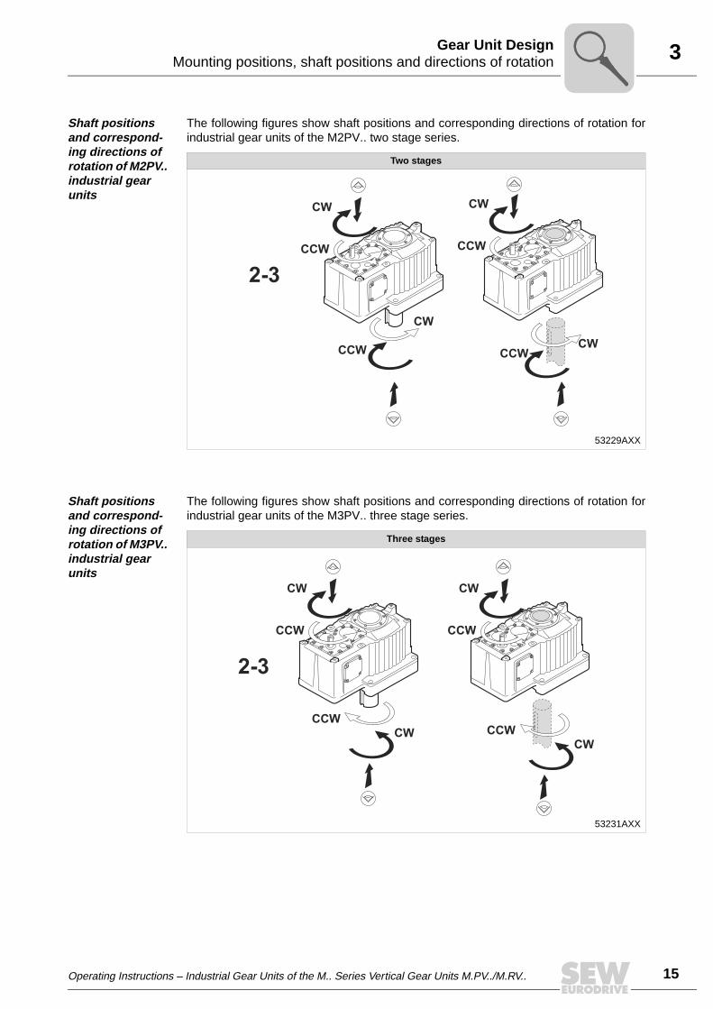
Shaft positions and correspond-ing directions of rotation of M2PV.. industrial gear units
The following figures show shaft positions and corresponding directions of rotation forindustrial gear units of the M2PV.. two stage series.
Shaft positions and correspond-ing directions of rotation of M3PV.. industrial gear units
The following figures show shaft positions and corresponding directions of rotation forindustrial gear units of the M3PV.. three stage series.
Two stages
53229AXX
2-3
CCW
CCW
CW
CW
CCW
CW
CCWCW
Three stages
53231AXX
2-3
CCW
CCW
CW
CW
CCW
CW
CCW
CW
3
16 Operating Instructions – Industrial Gear Units of the M.. Series Vertical Gear Units M.PV../M.RV..
Mounting positions, shaft positions and directions of rotationGear Unit Design
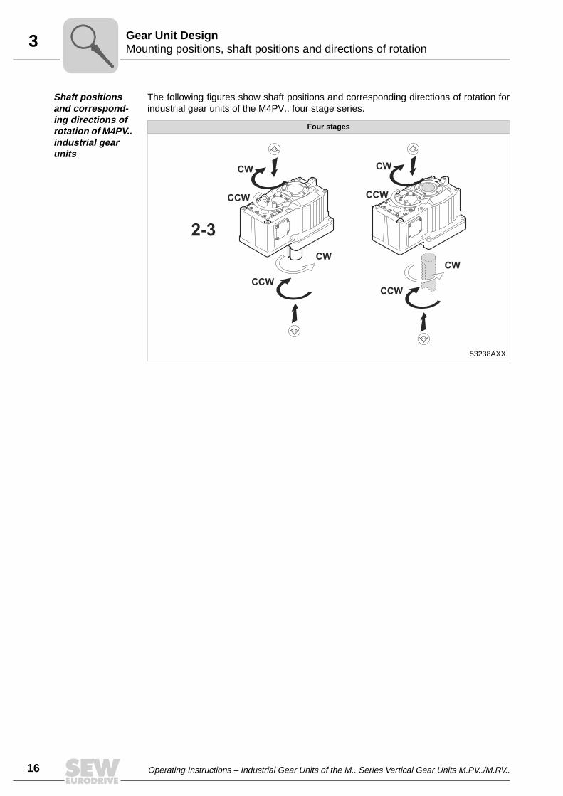
Shaft positions and correspond-ing directions of rotation of M4PV.. industrial gear units
The following figures show shaft positions and corresponding directions of rotation forindustrial gear units of the M4PV.. four stage series.
Four stages
53238AXX
2-3
CCW
CCW
CW
CW
CCW
CW
CCW
CW
Operating Instructions – Industrial Gear Units of the M.. Series Vertical Gear Units M.PV../M.RV.. 17
3Mounting positions, shaft positions and directions of rotationGear Unit Design
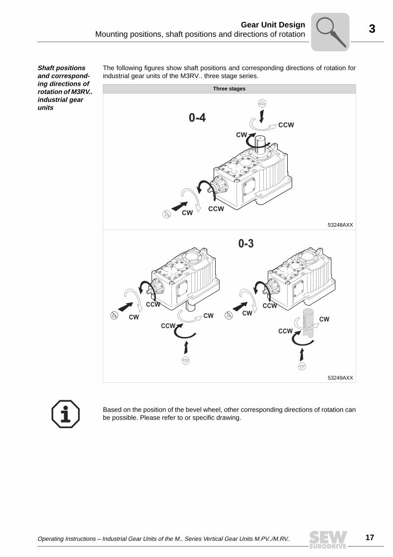
Shaft positions and correspond-ing directions of rotation of M3RV.. industrial gear units
The following figures show shaft positions and corresponding directions of rotation forindustrial gear units of the M3RV.. three stage series.
Three stages
53248AXX
53249AXX
0-4
CCWCW
CW
CCW
CCW
CWCCW
CWCWCCW
CW
CCW
0-3
Based on the position of the bevel wheel, other corresponding directions of rotation canbe possible. Please refer to or specific drawing.

3
18 Operating Instructions – Industrial Gear Units of the M.. Series Vertical Gear Units M.PV../M.RV..
Mounting positions, shaft positions and directions of rotationGear Unit Design
Shaft positions and correspond-ing directions of rotation of M4RV.. industrial gear units
The following figures show shaft positions and corresponding directions of rotation forindustrial gear units of the M4RV.. four stage series.
Four stages
53251AXX
53252AXX
0-4
CCWCW
CW
CCW
CW
CCW
CW
CCWCW
CCW
CW
CCW
0-3
Based on the position of the bevel wheel, other corresponding directions of rotation canbe possible. Please refer to or specific drawing.
Operating Instructions – Industrial Gear Units of the M.. Series Vertical Gear Units M.PV../M.RV.. 19
3Lubrication of industrial gear unitsGear Unit Design
3.5 Lubrication of industrial gear units
For M.. gear units in vertical design, the lubrication types "bath lubrication" or pressurelubrication" are normally used.
Oil bath lubrication
With oil bath lubrication, the oil level is so high that the bearings and gearing compo-nents are completely submerged in the lubricant.
Oil expansion tanks are always used for industrial gear units of the M.PV.., M.RV..series with oil bath lubrication. Oil expansion tanks allow the lubricant to expandwhen the gear unit heats up during operation.
Disregarding the mounting position, a steel oil expansion tank is used when the unitis installed outdoors and when the ambient conditions are very humid. This tank can beused both for the version with solid shaft and hollow shaft. A membrane in the oil expan-sion tank separates the oil in the gear unit from the humid ambient air. This way, nohumidity can build up in the gear unit.
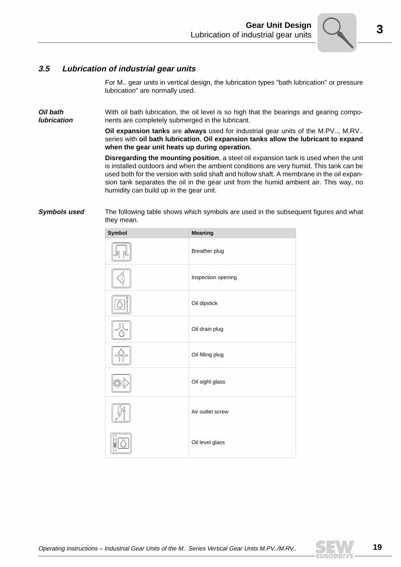
Symbols used The following table shows which symbols are used in the subsequent figures and whatthey mean.
Symbol Meaning
Breather plug
Inspection opening
Oil dipstick
Oil drain plug
Oil filling plug
Oil sight glass
Air outlet screw
Oil level glass
3
20 Operating Instructions – Industrial Gear Units of the M.. Series Vertical Gear Units M.PV../M.RV..
Lubrication of industrial gear unitsGear Unit Design
Oil bath lubrication vertical mount-ing position
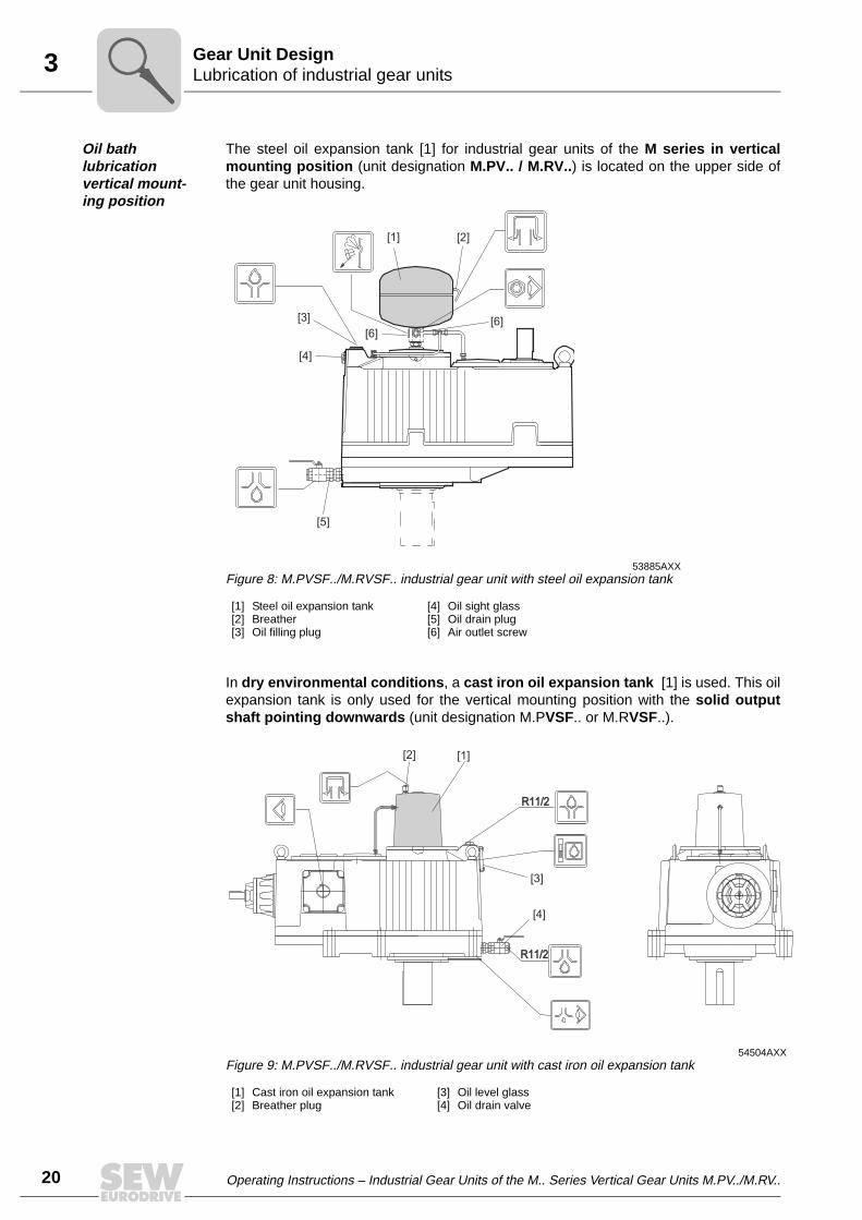
The steel oil expansion tank [1] for industrial gear units of the M series in verticalmounting position (unit designation M.PV.. / M.RV..) is located on the upper side ofthe gear unit housing.
In dry environmental conditions, a cast iron oil expansion tank [1] is used. This oilexpansion tank is only used for the vertical mounting position with the solid outputshaft pointing downwards (unit designation M.PVSF.. or M.RVSF..).
53885AXXFigure 8: M.PVSF../M.RVSF.. industrial gear unit with steel oil expansion tank
[1] Steel oil expansion tank[2] Breather[3] Oil filling plug
[4] Oil sight glass[5] Oil drain plug[6] Air outlet screw
54504AXXFigure 9: M.PVSF../M.RVSF.. industrial gear unit with cast iron oil expansion tank
[1] Cast iron oil expansion tank[2] Breather plug
[3] Oil level glass[4] Oil drain valve
[5]
[4]
[3]
[1] [2]
[6][6]
R11/2R11/2
R11/2R11/2
[2] [1]
[3]
[4]

Operating Instructions – Industrial Gear Units of the M.. Series Vertical Gear Units M.PV../M.RV.. 21
3Lubrication of industrial gear unitsGear Unit Design
Pressure lubrication
If requested, pressure lubrication is possible as lubrication method disregarding themounting position.
With pressure lubrication, the oil level is low. The gearing components and bearings notsubmerged in the oil bath are lubricated through a shaft end pump (→ Sec. "Shaft endpump") or through a motor pump (Sec. → "Motor pump").
The lubrication method "pressure lubrication" is used when
• oil bath lubrication is not desired for vertical mounting positions
• input speeds are very high
• the gear unit must be cooled by an external oil/water (→ Sec. "Oil/water coolingsystem") or oil/air cooling system (→ Sec. "Oil/air cooling system")
• the pitch line velocity is too high for splash or bath lubrication
• a drywell sealing system is used on the LSS
For more details on oil expansion tanks, refer to Sec. "Mounting Positions".

4
22 Operating Instructions – Industrial Gear Units of the M.. Series Vertical Gear Units M.PV../M.RV..
Required tools / resourcesMechanical Installation
4 Mechanical Installation4.1 Required tools / resources
Not included in the scope of delivery:
• Wrench set
• Torque wrench (for shrink discs)
• Mounting device
• Shims and spacing rings if necessary
• Fasteners for input and output elements
• Lubricant (e.g. NOCO® fluid from SEW-EURODRIVE)
• For hollow shaft gear units (→ Sec. "Mounting/removal of hollow shaft gear units withkeyed connection): Threaded rod, nut (DIN 934), retaining screw, ejector screw, endplate
• Securing components according to Sec. "Gear unit foundation"
Installation tolerances
4.2 Before you begin
The drive may only be installed if
• the data on the nameplate of the motor match the supply voltage
• the drive is not damaged (no damage resulting from transport or storage) and
• the following requirements have been properly met:
– with standard gear units:ambient temperature according to the lubricant table in Sec. "Lubricants" (seestandard), no oil, acid, gas, vapors, radiation, etc.
– with special versions:drive configured in accordance with the ambient conditions (→ order documents)
4.3 Preliminary work
Output shafts and flange surfaces must be completely free of anti-corrosion agents,contamination or other impurities (use a commercially available solvent). Do not let thesolvent get in contact with the sealing lips of the oil seals: danger of damage to thematerial!
Shaft end Flanges
Diametric tolerance in accordance with DIN 748• ISO k6 for solid shafts with ∅ ≤ 50 mm• ISO m6 for solid shafts with ∅ > 50 mm• ISO H7 for hollow shafts for shrink disc• ISO H8 for hollow shafts with keyway• Center hole in accordance with DIN 332, shape DS..
Centering shoulder tolerance:• ISO js7 / H8

Operating Instructions – Industrial Gear Units of the M.. Series Vertical Gear Units M.PV../M.RV.. 23
4Gear unit foundationMechanical Installation
4.4 Gear unit foundation
Foundation for foot-mounted gear units
To ensure quick and successful mounting, the type of foundation should be correctlyselected and the mounting carefully planned in advance. Foundation drawings with allnecessary construction and dimension details should be available.
SEW-EURODRIVE recommends foundation methods shown in the following figures. Acustomer’s own foundation method must be equally adequate.
When mounting a gear unit onto steel framework, special attention should be paid to therigidity of this framework to prevent destructive vibrations and oscillations. The founda-tion must be dimensioned according to weight and torque of the gear unit by taking intoaccount the forces acting on the gear unit.
Example
page Pos. "A" → Sec. "Concrete base" page 24 and page 25
52266AXXFigure 10: Reinforced concrete foundation for M..V.F..
[1] Hex head screw or stud[2] Hex nut if [1] is a stud or an upside-down screw[3] Shims (about 3 mm space for shims)[4] Hex nut[5] Foundation bracket
[6] Hex nut[7] Hex nut and foundation screw[9] Supporting girder[10]Shaft end pump (optional)
A A
[1][2]
[10]
[3]
[5]
[6] [9] [7]
�40 mm
[4]
Important for M.PV.. / M.RV.. gear unit types:
• The mounting clearance between bearing cover and gear unit foundation mustbe at least 40 mm.
• The mounting clearance must be dimensioned adequately if the gear unit isequipped with a shaft end pump [10] (→ Sec. "Shaft end pump")
4
24 Operating Instructions – Industrial Gear Units of the M.. Series Vertical Gear Units M.PV../M.RV..
Gear unit foundationMechanical Installation
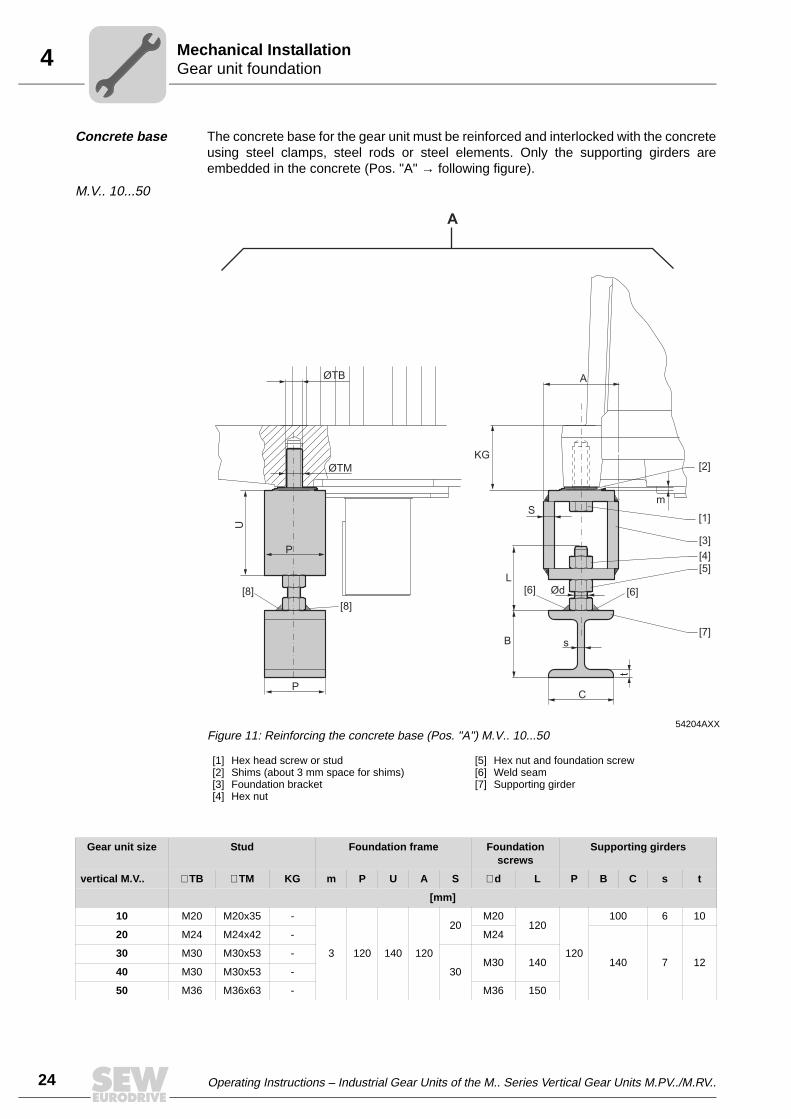
Concrete base The concrete base for the gear unit must be reinforced and interlocked with the concreteusing steel clamps, steel rods or steel elements. Only the supporting girders areembedded in the concrete (Pos. "A" → following figure).
M.V.. 10...50
54204AXXFigure 11: Reinforcing the concrete base (Pos. "A") M.V.. 10...50
[1] Hex head screw or stud[2] Shims (about 3 mm space for shims)[3] Foundation bracket[4] Hex nut
[5] Hex nut and foundation screw[6] Weld seam[7] Supporting girder
ØTB A
KG
[8][8]
[6][6]L
s
S
ØTM
Ød
C
m
B
P
P
U
A
[2]
[1]
[3]
[5]
[7]
[4]
t
Gear unit size Stud Foundation frame Foundation screws
Supporting girders
vertical M.V.. ∅ TB ∅ TM KG m P U A S ∅ d L P B C s t
[mm]
10 M20 M20x35 -
3 120 140 120
20M20
120
120
100 6 10
20 M24 M24x42 - M24
140 7 1230 M30 M30x53 -
30M30 140
40 M30 M30x53 -
50 M36 M36x63 - M36 150

Operating Instructions – Industrial Gear Units of the M.. Series Vertical Gear Units M.PV../M.RV.. 25
4Gear unit foundationMechanical Installation
M.V.. 60...90
54195AXXFigure 12: Reinforcing the concrete base (Pos. "A") M.V.. 60...90
[1] Hex head screw or stud[2] Hex nut if [1] is a stud or an upside-down screw[3] Shims (about 3 mm space for shims)[4] Hex nut[5] Foundation bracket
[6] Hex nut[7] Hex nut and foundation screw[8] Weld seam[9] Supporting girder
ØTB A
KG
[8][8]
[8][8]L
s
S
ØTM
Ød
C
m
B
P
P
U
A
[1][2]
[3]
[4]
[5]
[7]
[9]
[6]
t
Gear unit size Stud Foundation frame Foundation screws
Supporting girders
vertical M.V.. ∅ TB ∅ TM KG m P U A S ∅ d L P B C s t
[mm]
60
M42 48
165
3 150 180 200 36 M42 185 150 180 8,5 1470 171
80 182
90 188
The minimum tensile strength of the supporting girders and foundation screws must beat least 350 N/mm2.

4
26 Operating Instructions – Industrial Gear Units of the M.. Series Vertical Gear Units M.PV../M.RV..
Gear unit foundationMechanical Installation
Grouting The density of the grout must be equal to that of the base concrete. The grout isconnected with the concrete base using concrete reinforcement steel.
Before welding the weld seams [8], ensure that
• the concrete base around the supporting girder has dried
• the gear unit with all mount-on components has been aligned to its final position
Tightening torques
Gear unit size M.V.. Screw Tightening torque screw / nut
vertical [Nm]
10 M20 315
20 M24 540
30 M30 1090
40 M30 1090
50 M36 1900
Gear unit size M.V.. Screw / nut Tightening torque screw / nut
vertical [Nm]
60
M42 304570
80
90

Operating Instructions – Industrial Gear Units of the M.. Series Vertical Gear Units M.PV../M.RV.. 27
4Gear unit foundationMechanical Installation
Counterflange for flange mounted gear units
Gear units M..PV10..50 / M..RV10…50 with LSS in downwards direction (Solid or hollowshaft) can be supplied with a mounting flange on the LSS:
Mounting flange dimensions
The counterflange must have the following characteristics:
• Stiff and torsionally rigid, taking into consideration
– gear unit weight– motor weight– the torque that has to be transmitted – additional forces acting on the gear unit from the customer machine (e.g. axial
forces from and towards gear unit from a mixing process)
• Horizontal
• Plain
• Vibration isolating, that means no vibrations are to be transmitted from close-by ma-chines and elements
• Not creating resonance vibration
• A centering shoulder ∅ FC with js7-fitting according to picture (→ Figure 13)
53888AXXFigure 13: Mounting flange for flange mounted gear units
BB
L FL YF
HF
V2
FFD
FC js7/H8
Ø QF
45°
22.5
°
Gear unit sizevertical M.V..
F FD FC js 7/H8 ∅ QF L FL YF HF V2
[mm]
10 450 400 350 18 6 24 65 110 175
20 480 430 380 22 6 25 65 110 175
30 560 500 450 26 6 30 105 110 215
40 660 600 550 26 7 36 105 110 215
50 820 740 680 33 7 45 140 110 250
The mounting surface of mounting flange and counter flange must be absolutelyfree of grease or oil and from other contamination (e.g. small textile particles,dust, ….).

4
28 Operating Instructions – Industrial Gear Units of the M.. Series Vertical Gear Units M.PV../M.RV..
Mounting of solid shaft gear unitsMechanical Installation
The alignment of the gear unit LSS in relation to the counterflange has to be asaccurately as possible. Correct alignment has an effect on the lifetime of bearing, shaftsand coupling.
For permitted misalignments for the coupling on the LSS, please refer to Sec. 5.2 or toa separate coupling manual.
Following bolts of the 8.8-class should be used (Tensile strength 640 N/mm2):
4.5 Mounting of solid shaft gear units
Foot mounted gear units
Mount the gear unit in the following order:
1. Mount the components according to Sec. "Gear unit foundation". The shims [1] (→Figure 16) facilitate later adjustment and, if necessary, to mount a replacement gearunit.
2. Secure the gear unit at the selected positions on the supporting girders using threefoundation screws. Position the foundation screws at maximum possible distance(two screws on one side of the gear unit and one on the other side). Align the gearunit as follows:
– vertically by lifting, lowering or tilting the unit using the nuts of the foundationscrews
– horizontally by tapping the foundation screws slightly into the required direction
3. After having aligned the gear unit, tighten the three nuts of the foundation screwsused for alignment. Carefully insert the fourth foundation screw into the supportinggirder and tighten it securely. When doing so, make sure that the position of the gearunit does not change. If necessary, realign the gear unit.
4. Tack-weld the ends of the foundation screws to the supporting girders (at least threewelding spots per foundation screw). Tack-weld the foundation screws alternately inboth directions (starting from the middle) on each side of the center line of the gearunit. This way, misalignment caused by the welding process is avoided. After havingtack-welded all screws, they must be welded all the way round in the abovementioned order. Adjust the nuts on the foundation screws to ensure that the weldedfoundation screws do not twist the gear unit housing.
5. After having tack-welded the nuts of the retaining screws of the gear unit, check themounting and carry out grouting.
6. When the grouting concrete has set, check the mounting a last time and adjust, ifnecessary.
Gear unit size MP.V.. / MR.V.. Bolt size
10 M16
20 M20
30 M24
40 M24
50 M30
Before mounting the gear unit, check the foundation dimensions with those in thecorresponding drawings in Sec. "Gear unit foundation."

Operating Instructions – Industrial Gear Units of the M.. Series Vertical Gear Units M.PV../M.RV.. 29
4Mounting of solid shaft gear unitsMechanical Installation
Flange mounted gear units
Mount the gear unit in the following order:
1. Lower the gear unit on the counterflange using suitable lifting means. Observe theguidelines mentioned in Sec. 2.1.
2. Secure the gear unit at the correct position on the counterflange using the flangebolts and tighten them crosswise to full tightening torque (see Sec. 4.4).
Mounting accuracy when aligning
When aligning the gear unit, make sure that the mounting tolerances for the evennessof the foundation are not exceeded (values ymax in below table). If necessary, use shims[1] to align the gear unit on the foundation plate.
Before mounting the gear unit, check if the counterflange fullfils the requirementsmentioned in Sec. "4.4 Gear unit foundation - Counterflange for flange mounted gearunits"
53886AXXFigure 14: Mounting accuracy when aligning
JE [mm] ymax [mm]
< 400 0.035
400 ... 799 0.06
800 ... 1200 0.09
1200 ... 1600 0.125
1600 ... 2000 0.15
JEJE
Y
[1]

4
30 Operating Instructions – Industrial Gear Units of the M.. Series Vertical Gear Units M.PV../M.RV..
Mounting / removing hollow shaft gear units with keyed connectionMechanical Installation
4.6 Mounting / removing hollow shaft gear units with keyed connection
Selecting the adequate thread and length of the threaded rod depends on the design ofthe customer’s machine.
Thread sizes SEW-EURODRIVE recommends the following thread sizes:
The thread size of the ejector screw depends on the end plate [4]:
• Not included in the scope of delivery (→ Figure 15, Figure 16, Figure 17)
– Threaded rod [2], nut [5], retaining screw [6], ejector screw [8]
• Included in the scope of delivery
– Circlips [3], end plate [4]
Gear unit size Quantity Thread size for
verticalM.V..
• threaded rod [2]• nut (DIN 934) [5]
• retaining screw [6]
(Figure 15, Figure 16)
10
1
M20
20 M24
30 M24
40 M24
50 M30
60 M30
70
2
M20
80 M20
90 M24
Gear unit size Quantity Thread size for
verticalM.V..
• ejector screw [8]
(Figure 17)
10
1
M24
20 M30
30 M30
40 M30
50 M36
60 M36
70
2
M24
80 M24
90 M30

Operating Instructions – Industrial Gear Units of the M.. Series Vertical Gear Units M.PV../M.RV.. 31
4Mounting / removing hollow shaft gear units with keyed connectionMechanical Installation
Mounting the hollow shaft gear unit onto the customer’s shaft
To mount and secure the gear unit, attach the circlips [3] and the end plate [4] on thehollow shaft bore.
• Apply NOCO® fluid to the hollow shaft [7] and the shaft end of the customer’s shaft[1].
• Push the gear unit onto the customer’s shaft [1]. Thread the threaded rod [2] into thecustomer’s shaft [1]. Tighten the customer’s shaft [1] with the nut [5] until the shaftend of the customer’s shaft [1] and the end plate [4] meet.
• Loosen the nut [5] and unscrew the threaded rod [2]. After having mounted the gearunit, secure the customer’s shaft [1] using the retaining screw [6].
52657AXXFigure 15: Mounting of vertical gear unit with keyed connection
[1] Customer’s shaft[2] Threaded rod
[3] Circlips[4] End plate
[5] Nut[7] Hollow shaft
52656AXXFigure 16: Mounted vertical gear unit with keyed connection
[1] Customer’s shaft[3] Circlips
[4] End plate[6] Retaining screw
[7] Hollow shaft
Ø � 180 Ø � 180
X
[2]
[7]
[1]
[5][3] [4]
X
[1]
[6] [4]
[7]
[3]
Ø �180Ø � 180
X
X

4
32 Operating Instructions – Industrial Gear Units of the M.. Series Vertical Gear Units M.PV../M.RV..
Mounting / removing hollow shaft gear units with keyed connectionMechanical Installation
Removing the hollow shaft gear unit from the customer’s shaft
• Remove the retaining screw (→ Figure 16, Pos. 6).
• Thread the ejector screw [8] into the end plate [4] to remove the gear unit from thecustomer’s shaft [1].
52658AXXFigure 17: Removing of vertical gear unit with keyed connection
[1] Customer’s shaft[3] Circlips
[4] End plate[8] Ejector screw
Ø �180 Ø �180
[8] [3]
[1]
[4]
X
X

Operating Instructions – Industrial Gear Units of the M.. Series Vertical Gear Units M.PV../M.RV.. 33
4Mounting / removing hollow shaft gear units with shrink discMechanical Installation
4.7 Mounting / removing hollow shaft gear units with shrink disc
A shrink disc serves as connecting element between the hollow shaft of the gear unitand the customer’s shaft. For the shrink disc type used (unit designation: 3171 or RLK 608), refer to the order documents.
Selecting the appropriate thread and length of the threaded rod as well as the retainingscrew depends on the design of the customer’s machine.
Thread sizes SEW-EURODRIVE recommends the following thread sizes:
The thread size of the ejector screw depends on the end plate [4]:
• Figure Included in the scope of delivery (→ Figure 19, Figure 20, Figure 21)
– [12] protection cover; optional: shrink disc with locking srews [10]
• Not included in the scope of delivery (→ Figure 19, Figure 20, Figure 21)
– Threaded rod [2], nut [5], ejector screw [8], end plate screws [3], endplate [4]
Gear unit size Quantity Thread size for
verticalM.V..
• threaded rod [2]• nut (DIN 934) [5]
(→ Figure 19)
10
1
M20
20 M24
30 M24
40 M24
50 M30
60 M30
70
2
M20
80 M20
90 M24
Gear unit size Quantity Thread size for
verticalM.V..
• ejector screw [8]
(→ Figure 21)
10
1
M24
20 M30
30 M30
40 M30
50 M36
60 M36
70
2
M24
80 M24
90 M30

4
34 Operating Instructions – Industrial Gear Units of the M.. Series Vertical Gear Units M.PV../M.RV..
Mounting / removing hollow shaft gear units with shrink discMechanical Installation
Recommended dimension of end plate [4] → Figure 19
Gear unit size Quantity of Recommended screw
verticalM.V..
• end plate screws [3]
(→ Figure 19)
10
6 x 60°
M6 x 2220
30
40 M8 x 28
50M10 x 35
60
70
M12 x 5080
90
53412AXXFigure 18: End plate design
Gear unit sizevertical
DS t DP ZP Z c
M.V.. [mm] 6 x 60° [mm]
10 110 10 97
M6
1 x M20 -
20 120 10 107 1 x M24 -
30 150 12 135 1 x M24 -
40 160 12 145 M8 1 x M24 -
50 190 15 172M10
1 x M30 -
60 220 15 200 1 x M30 -
70 240 18 215
M12
2 x M20 114
80 260 25 235 2 x M20 126
90 300 25 275 2 x M24 144
cZ Z
t
ZP
DP
DS

Operating Instructions – Industrial Gear Units of the M.. Series Vertical Gear Units M.PV../M.RV.. 35
4Mounting / removing hollow shaft gear units with shrink discMechanical Installation
Mounting the hollow shaft gear unit onto the customer’s shaft
• Before mounting the gear unit, degrease the hollow shaft bore and the customer’sshaft [1].
• To mount and secure the gear unit, attach the end plate [4] with the end plate screws[3] on the hollow shaft [7].
• Push the gear unit onto the customer’s shaft [1]. Thread the threaded rod [2] into thecustomer’s shaft [1]. Tighten the customer’s shaft [1] with the nut [5] until the shaftend of the customer’s shaft [1] and the end plate [4] meet.
• Loosen the nut [5] and unscrew the threaded rod [2].
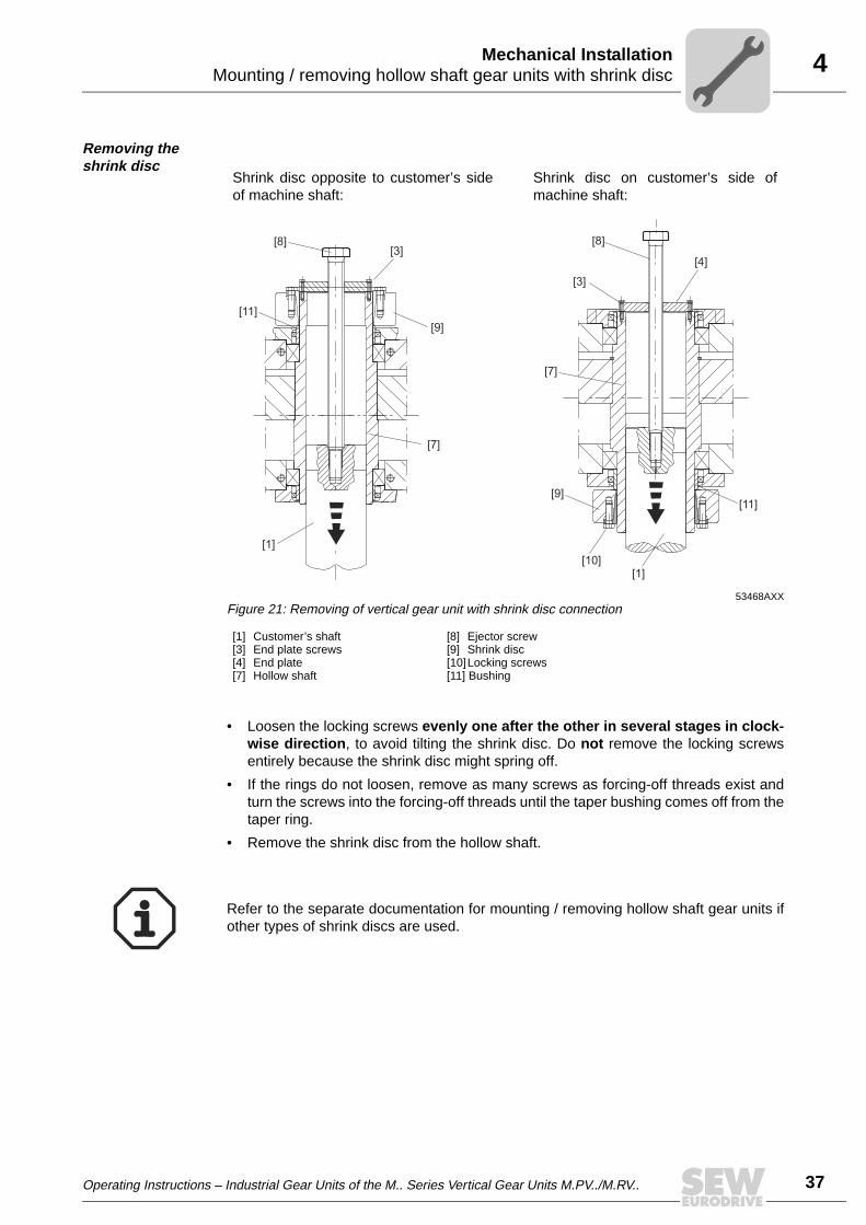
Shrink disc opposite to customer’s sideof machine shaft:
Shrink disc on customer’s side ofmachine shaft:
53464AXXFigure 19: Mounting of vertical gear unit with shrink disc connection
[1] Customer’s shaft[2] Threaded rod[3] End plate screws[4] End plate[5] Nut
[7] Hollow shaft[9] Shrink disc[10] Locking screws[11] Bushing
[7]
[9]
[4] [10]
[2][3] [5]
[11]
[1]
[2] [5] [4]
[9]
[1]
[11]
[3]
[7]

4
36 Operating Instructions – Industrial Gear Units of the M.. Series Vertical Gear Units M.PV../M.RV..
Mounting / removing hollow shaft gear units with shrink discMechanical Installation
Mounting the shrink disc
• Do not tighten the locking screws [10] before the customer’s shaft [1] has beenmounted, else the hollow shaft could be deformed!
• Apply a small amount of NOCO® fluid to the area where the shrink disc [9] is seatedon the hollow shaft.
• Slide the shrink disc [9] with untightened locking screws [10] onto the hub of thehollow shaft bore until the shrink disc touches the bushing [11]. Position the custom-er’s shaft [1] in the hollow shaft bore.
Tightening torques Tighten all locking screws [10] of the shrink disc [9] evenly in several stages one afterother in clockwise direction (not diametrically). Repeat the process until all lockingscrews [10] have reached the required thightening torque.
Mounted hollow shaft gear unit
Gear unit size M...
Shrink disc type 3171 Shrink disc type RLK608
Screw size(class 10.9)
Tightening torque[Nm]
Tightening torque[Nm]
10, 20 M12 100
The required tightening torque is reached when the faces of outer and inner ring are in line.
30, 40 M14 160
50 M16 250
60, 70, 80 M20 490
90 M24 840
Shrink disc opposite to customer’s sideof machine shaft:
Shrink disc on customer’s side ofmachine shaft:
53467AXXFigure 20: Mounted vertical gear unit with shrink disc connection
[1] Customer’s shaft[7] Hollow shaft[9] Shrink disc
[10] Locking screws[11] Bushing[12] Protection cover
[12]
[11]
[1]
[7]
[9]
[10]
[9]
[1]
[7]
[11]
[10] [12]
Operating Instructions – Industrial Gear Units of the M.. Series Vertical Gear Units M.PV../M.RV.. 37
4Mounting / removing hollow shaft gear units with shrink discMechanical Installation
Removing the shrink disc
• Loosen the locking screws evenly one after the other in several stages in clock-wise direction, to avoid tilting the shrink disc. Do not remove the locking screwsentirely because the shrink disc might spring off.
• If the rings do not loosen, remove as many screws as forcing-off threads exist andturn the screws into the forcing-off threads until the taper bushing comes off from thetaper ring.
• Remove the shrink disc from the hollow shaft.
Shrink disc opposite to customer’s sideof machine shaft:
Shrink disc on customer’s side ofmachine shaft:
53468AXXFigure 21: Removing of vertical gear unit with shrink disc connection
[1] Customer’s shaft[3] End plate screws[4] End plate[7] Hollow shaft
[8] Ejector screw[9] Shrink disc[10]Locking screws[11] Bushing
[3]
[10]
[8]
[4]
[7]
[9]
[8][3]
[9]
[1]
[7]
[1]
[11]
[11]
Refer to the separate documentation for mounting / removing hollow shaft gear units ifother types of shrink discs are used.

4
38 Operating Instructions – Industrial Gear Units of the M.. Series Vertical Gear Units M.PV../M.RV..
Mounting a motor with motor adapterMechanical Installation
4.8 Mounting a motor with motor adapter
Motor adapters [1] are available for mounting IEC motors of sizes 132 to 355 to industrialgear units of the M series.
For the assembly clearance between the motor shaft end and the shaft end of the gearunit, please refer to Sec. "5.2 coupling" or to a separate coupling manual. The clearancecan be checked by opening the inspection cover of the motor adapter.
52665AXXFigure 22: Mounting a motor with motor adapter
[1] Motor adapter[2] Coupling
[1][2]
S2
For mounting couplings [2], refer to the notes in Sec. "Mounting of couplings."

Operating Instructions – Industrial Gear Units of the M.. Series Vertical Gear Units M.PV../M.RV.. 39
5Important installation instructionsMechanical Installation Options
5 Mechanical Installation Options5.1 Important installation instructions
Important installation notes
• Only use a mounting device for installing input and output elements. Use the centerbore and the thread on the shaft end for positioning purposes.
• Power transmission elements should be balanced after insertion and must not giverise to any impermissible radial or axial forces.
Adjust the following misalignments when mounting couplings:
a) Axial misalignment (maximum and minimum clearance)
b) Offset misalignment (concentric running fault)
c) Angular misalignment
Disconnect the motor from the power supply before starting work and secure itagainst unintentional restart!
• Never mount couplings, pinions, etc. onto the shaft end by hitting them with ahammer (damage to bearings, housing and the shaft!).
• Observe correct tension of the belt for belt pulleys (in accordance withmanufacturer’s specifications).
Note:
Installation is easier if you first apply lubricant to the output element or heat it up briefly(to 80 °C - 100 °C).
03356AXXFigure 23: Clearance and misalignment when mounting the coupling
a) b) c)
Input and output elements such as couplings must be equipped with a protectioncover!

5
40 Operating Instructions – Industrial Gear Units of the M.. Series Vertical Gear Units M.PV../M.RV..
Important installation instructionsMechanical Installation Options
Measuring of angular misalign-ment with a feeler gauge
The following figure shows the measurement for angular misalignment (α) using a feelergauge. When using this method, an accurate result is only achieved when the deviationof the coupling faces is eliminated by turning both coupling halves by 180° and theaverage value is then calculated from the difference (a1– a2).
Measuring of angular misalign-ment using a micrometer dial
The following figure shows the measurement for angular misalignment using amicrometer dial. This measuring method provides the same result as described under"Measuring angular offset with a feeler gauge" if the coupling halves are rotatedtogether, for instance with one coupling pin, so that the needle of the micrometer dialdoes not move noticeably on the measuring surface.
A prerequisite for this measuring method is that there is no axial play in the shaftbearings when the shafts rotate. If this condition is not fulfilled, the axial play betweenthe faces of the coupling halves must be eliminated. As an alternative, you can use twomicrometer dials positioned on the opposite sides of the coupling (to calculate thedifference of the two micrometer dials when rotating the coupling).
The following methods for measuring angular and axial misalignment areimportant for complying with the mounting tolerances specified in Sec."Mounting of couplings"!
52063AXXFigure 24: Measuring angular misalignment using a feeler gauge
a1
a2
a
Dα
52064AXXFigure 25: Measuring angular misalignment using a micrometer dial
a1
a2
a
Dα
f2 f1

Operating Instructions – Industrial Gear Units of the M.. Series Vertical Gear Units M.PV../M.RV.. 41
5Important installation instructionsMechanical Installation Options
Measuring of offset misalign-ment using straight-edge and micrometer dial
The following figure shows the measurement for offset misalignment using a straight-edge. Permissible values for eccentricity are usually so small that the best measurementresults can be achieved with a micrometer dial. If you rotate one coupling half togetherwith the micrometer dial and divide the deviation by two, the micrometer dial will indicatethe deviation and as a result the misalignment (dimension "b"), which includes the offsetmisalignment of the other coupling half.
Measuring of offset misalign-ment using a micrometer dial
The following figure shows the measurement for offset misalignment using a moreaccurate measuring method. The coupling halves are rotated together without thetip of the micrometer dial moving on the measuring surface. The offset misalignment isobtained by dividing the deviation indicated on the micrometer dial (dimension "b").
52065AXXFigure 26: Measuring offset misalignment using straight-edge and micrometer dial
b
f2 f1
52066AXXFigure 27: Measuring offset misalignment using a micrometer dial
b
f2 f1

5
42 Operating Instructions – Industrial Gear Units of the M.. Series Vertical Gear Units M.PV../M.RV..
Mounting of couplingsMechanical Installation Options
5.2 Mounting of couplings
ROTEX coupling
The low-maintenance, elastic ROTEX coupling is capable of compensating radial andangular misalignment. Careful and exact alignment of the shaft ensures long service lifeof the coupling.
51663AXXFigure 28: Design of the ROTEX coupling
[1] Coupling hub[2] Ring gear
[1]
[1]
[2]

Operating Instructions – Industrial Gear Units of the M.. Series Vertical Gear Units M.PV../M.RV.. 43
5Mounting of couplingsMechanical Installation Options
Mounting the coupling halves onto the shaft
51689AXXFigure 29: Mounting dimensions of the ROTEX coupling
s s
G
E
L1
Ød H
Ød W
Coupling size
Mounting dimensions Locking screw
E[mm]
s[mm]
∅ dH[mm]
∅ dW[mm]
L1 (Alu / GG / GGG)[mm]
L1 (steel)[mm]
G Tightening torque[Nm]
14 13 1.5 10 7 - - M4 2.4
19 16 2 18 12 26 - M5 4.8
24 18 2 27 20 30 - M5 4.8
28 20 2.5 30 22 34 - M6 8.3
38 24 3 38 28 40 60 M8 20
42 26 3 46 36 46 70 M8 20
48 28 3.5 51 40 50 76 M8 20
55 30 4 60 48 56 86 M10 40
65 35 4.5 68 55 63 91 M10 40
75 40 5 80 65 72 104 M10 40
90 45 5.5 100 80 83 121 M12 69
100 50 6 113 95 92 - M12 69
110 55 6.5 127 100 103 - M16 195
125 60 7 147 120 116 - M16 195
140 65 7.5 165 135 127 - M20 201
160 75 9 190 160 145 - M20 201
180 85 10.5 220 185 163 - M20 201
The shaft distance must be strictly observed (dimension E) to ensure axial play ofthe coupling.

5
44 Operating Instructions – Industrial Gear Units of the M.. Series Vertical Gear Units M.PV../M.RV..
Mounting of couplingsMechanical Installation Options
Nor-Mex coupling, types G and E
The low-maintenance Nor-Mex couplings types G and E are torsionally flexiblecouplings capable of compensating axial, angular, and radial shaft misalignments.Torque is transmitted via an elastic element with high damping properties, which is alsooil and heat resistant. The couplings can be used for either direction of rotation and canbe mounted in any position. The design of the Nor-Mex coupling type G allows to replacethe elastic element [5] without movement of the shafts.
51667AXXFigure 30: Design of the Nor-Mex E / Nor-Mex G coupling
[1] Coupling hub [1] Socket head screw
[2] Elastic element [2] Washer
[3] Claw ring
[4] Flange hub
[5] Elastic element
[6] Coupling hub
[3]
[1]
[4]
[5]
[6]
[2]
[2]
[1]
[1]
Nor-Mex E Nor-Mex G
Operating Instructions – Industrial Gear Units of the M.. Series Vertical Gear Units M.PV../M.RV.. 45
5Mounting of couplingsMechanical Installation Options
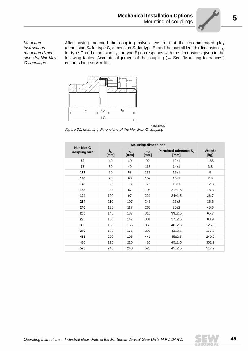
Mounting instructions, mounting dimen-sions for Nor-Mex G couplings
After having mounted the coupling halves, ensure that the recommended play(dimension S2 for type G, dimension S1 for type E) and the overall length (dimension LGfor type G and dimension LE for type E) corresponds with the dimensions given in thefollowing tables. Accurate alignment of the coupling (→ Sec. 'Mounting tolerances')ensures long service life.
51674AXXFigure 31: Mounting dimensions of the Nor-Mex G coupling
Nor-Mex GCoupling size
Mounting dimensions
lE[mm]
lG[mm]
LG[mm]
Permitted tolerance S2[mm]
Weight[kg]
82 40 40 92 12±1 1.85
97 50 49 113 14±1 3.8
112 60 58 133 15±1 5
128 70 68 154 16±1 7.9
148 80 78 176 18±1 12.3
168 90 87 198 21±1.5 18.3
194 100 97 221 24±1.5 26.7
214 110 107 243 26±2 35.5
240 120 117 267 30±2 45.6
265 140 137 310 33±2.5 65.7
295 150 147 334 37±2.5 83.9
330 160 156 356 40±2.5 125.5
370 180 176 399 43±2.5 177.2
415 200 196 441 45±2.5 249.2
480 220 220 485 45±2.5 352.9
575 240 240 525 45±2.5 517.2
IE IG
LG
S2

5
46 Operating Instructions – Industrial Gear Units of the M.. Series Vertical Gear Units M.PV../M.RV..
Mounting of couplingsMechanical Installation Options
Mounting dimensions of the Nor-Mex E coupling
51674AXXFigure 32: Mounting dimensions of the Nor-Mex E coupling
Nor-Mex ECoupling size
Mounting dimensions
lE[mm]
LE[mm]
Permitted tolerance S1[mm]
Weight[kg]
67 30 62.5 2.5± 0.5 0.93
82 40 83 3± 1 1.76
97 50 103 3± 1 3.46
112 60 123.5 3.5± 1 5
128 70 143.5 3.5± 1 7.9
148 80 163.5 3.5± 1.5 12.3
168 90 183.5 3.5± 1.5 18.4
194 100 203.5 3.5± 1.5 26.3
214 110 224 4± 2 35.7
240 120 244 4± 2 46.7
265 140 285.5 5.5± 2.5 66.3
295 150 308 8± 2.5 84.8
330 160 328 8± 2.5 121.3
370 180 368 8± 2.5 169.5
415 200 408 8± 2.5 237
480 220 448 8± 2.5 320
575 240 488 8± 2.5 457
IE IE
LE
S1
Operating Instructions – Industrial Gear Units of the M.. Series Vertical Gear Units M.PV../M.RV.. 47
5Mounting of couplingsMechanical Installation Options
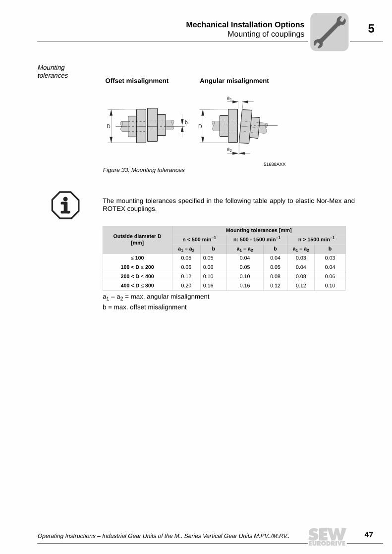
Mounting tolerances
a1 – a2 = max. angular misalignment
b = max. offset misalignment
Offset misalignment Angular misalignment
51688AXXFigure 33: Mounting tolerances
D Db
a2
a1
The mounting tolerances specified in the following table apply to elastic Nor-Mex andROTEX couplings.
Outside diameter D[mm]
Mounting tolerances [mm]
n < 500 min–1 n: 500 - 1500 min–1 n > 1500 min–1
a1 – a2 b a1 – a2 b a1 – a2 b
≤ 100 0.05 0.05 0.04 0.04 0.03 0.03
100 < D ≤ 200 0.06 0.06 0.05 0.05 0.04 0.04
200 < D ≤ 400 0.12 0.10 0.10 0.08 0.08 0.06
400 < D ≤ 800 0.20 0.16 0.16 0.12 0.12 0.10

5
48 Operating Instructions – Industrial Gear Units of the M.. Series Vertical Gear Units M.PV../M.RV..
Mounting of couplingsMechanical Installation Options
Mounting of torsionally rigid GM, GMD, and GMX couplings
• Before mounting the coupling, thoroughly clean the individual parts of the coupling,in particular the toothing.
• Grease the O-rings [6] slightly and place them into the corresponding grooves in thesleeve [2, 3].
• Grease the toothing of the sleeves [2,3] and push the sleeves onto the shaft endswithout damaging the O-rings [6].
• Slide the coupling hubs [1] onto the shaft. Move hubs to be flush with the shaft end.
• Align the machine to be coupled and check the shaft distance (dimension "a" → Sec."Shaft distance, tightening torque").
• Align both axes and check the permitted values using a dial indicator. The mountingtolerances (→ Sec. "Mounting tolerances") depend on the coupling torque.
• Before you screw on the sleeves [2, 3], have the coupling hubs [1] cool off and greasethe toothing.
• Insert the gasket [10] and tighten the sleeve halves to the specified tightening torque(→ Sec. "Shaft distance, tightening torque"). Grease the gasket slightly to facilitatemounting.
• It is important that the grease nipples [9] on the two sleeve halves [4, 5] arepositioned at an angle of 90° towards each other after having tightened the sleeves.
53262AXXFigure 34: Design of the GM coupling
[1] Coupling hub[2] Sleeve[3] Sleeve[4] Sleeve (male)[5] Sleeve (female)[6] Seal or O-ring[7] Cover[8] Grease nipple[9] Grease nipple
[10] Gasket[11] Bolt[12] Self-locking nut[13] Washerr[14] Nut[15] Bolts[16] Washer[16] O-ring
GM 280-800 GM 42-260
[9,8] [9,8] [13,14][1] [6] [6][3] [4] [5] [7]
[1]
[15,16]
[11] [11] [10][12] [17][2] [1][1]

Operating Instructions – Industrial Gear Units of the M.. Series Vertical Gear Units M.PV../M.RV.. 49
5Mounting of couplingsMechanical Installation Options
Mounting tolerances
a1 – a2 = max. angular misalignment
bmax = max. offset misalignment
Shaft distance, tightening torque
Offset misalignment Angular misalignment
51690AXXFigure 35: Mounting tolerances of the GM coupling
bmax
a2
a1
Coupling type
Mounting tolerances [mm]
n < 250 min–1 n: 250 -500 min–1 n: 500-1000min–1 n: 1000-2000min–1 n: 2000-4000min–1
a1 – a2 bmax a1 – a2 bmax a1 – a2 bmax a1 – a2 bmax a1 – a2 bmax
GM42 ... 90 0.25 0.25 0.25 0.25 0.25 0.25 0.2 0.15 0.1 0.08
GM100 ... 185 0.6 0.5 0.6 0.5 0.35 0.25 0.2 0.15 0.1 0.08
GM205 ... 345 1 0.9 0.75 0.5 0.35 0.25 0.2 0.15 - -
GM370 ... 460 2 1.5 1.1 0.8 0.5 0.4 0.25 0.2 - -
GM500 ... 550 2.2 1.5 1.1 0.8 0.5 0.4 0.25 0.2 - -
54505AXXFigure 36: Shaft distance "a"
a
Coupling type 42 55 70 90 100 125 145 165 185 205 230 260 280
Shaft distance a [mm] 61 61 62 82 82 82 102 103 103 123 123 123 163
Tightening torque screw [Nm] 8 20 68 108 108 230 230 230 325 325 325 375 375
5
50 Operating Instructions – Industrial Gear Units of the M.. Series Vertical Gear Units M.PV../M.RV..
Oil heaterMechanical Installation Options
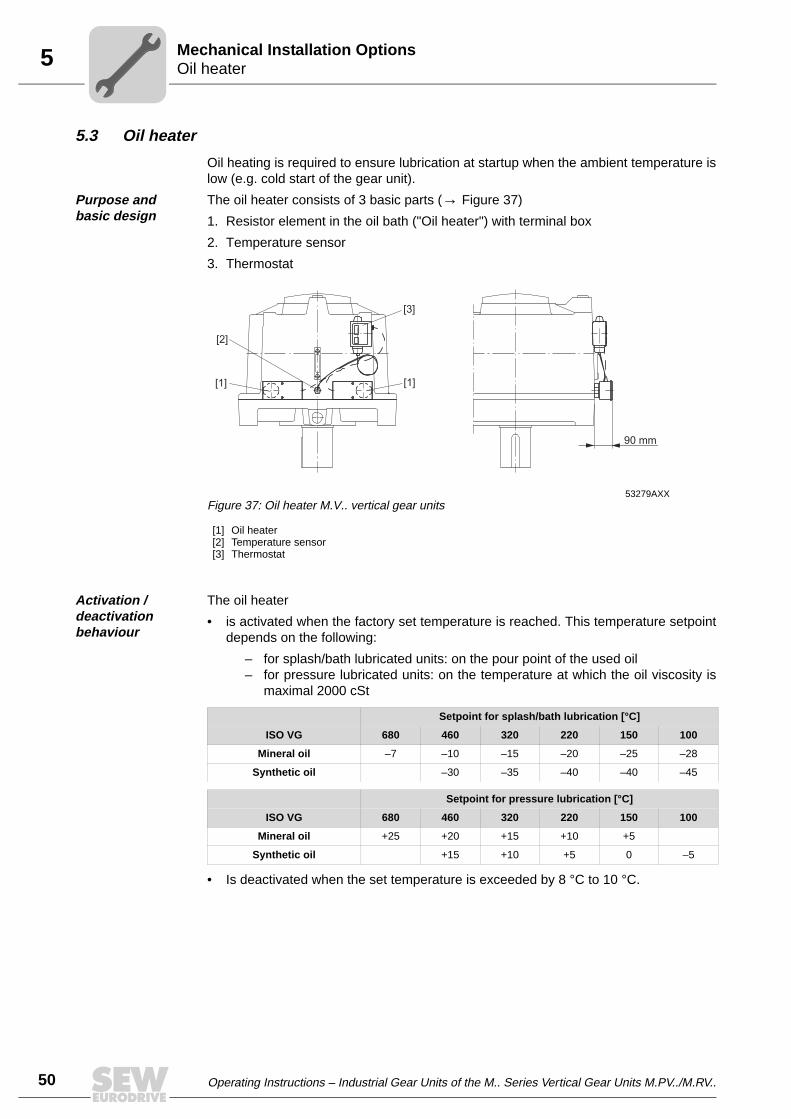
5.3 Oil heater
Oil heating is required to ensure lubrication at startup when the ambient temperature islow (e.g. cold start of the gear unit).
Purpose and basic design
The oil heater consists of 3 basic parts (→ Figure 37)
1. Resistor element in the oil bath ("Oil heater") with terminal box
2. Temperature sensor
3. Thermostat
Activation / deactivation behaviour
The oil heater
• is activated when the factory set temperature is reached. This temperature setpointdepends on the following:
– for splash/bath lubricated units: on the pour point of the used oil – for pressure lubricated units: on the temperature at which the oil viscosity is
maximal 2000 cSt
• Is deactivated when the set temperature is exceeded by 8 °C to 10 °C.
53279AXXFigure 37: Oil heater M.V.. vertical gear units
[1] Oil heater[2] Temperature sensor[3] Thermostat
90 mm
[2]
[1][1]
[3]
Setpoint for splash/bath lubrication [°C]
ISO VG 680 460 320 220 150 100
Mineral oil –7 –10 –15 –20 –25 –28
Synthetic oil –30 –35 –40 –40 –45
Setpoint for pressure lubrication [°C]
ISO VG 680 460 320 220 150 100
Mineral oil +25 +20 +15 +10 +5
Synthetic oil +15 +10 +5 0 –5
Operating Instructions – Industrial Gear Units of the M.. Series Vertical Gear Units M.PV../M.RV.. 51
5Oil heaterMechanical Installation Options
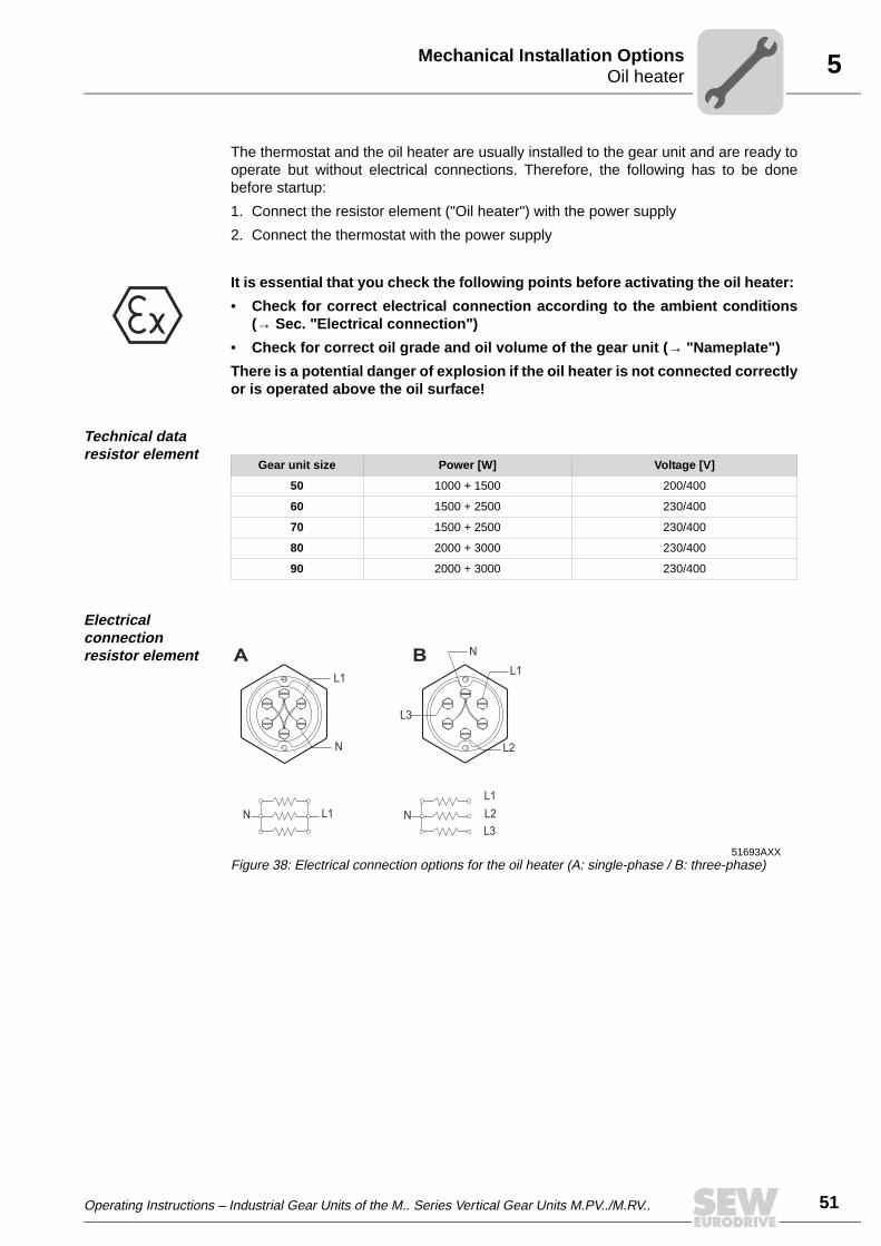
The thermostat and the oil heater are usually installed to the gear unit and are ready tooperate but without electrical connections. Therefore, the following has to be donebefore startup:
1. Connect the resistor element ("Oil heater") with the power supply
2. Connect the thermostat with the power supply
Technical data resistor element
Electrical connection resistor element
It is essential that you check the following points before activating the oil heater:
• Check for correct electrical connection according to the ambient conditions(→ Sec. "Electrical connection")
• Check for correct oil grade and oil volume of the gear unit (→ "Nameplate")
There is a potential danger of explosion if the oil heater is not connected correctlyor is operated above the oil surface!
Gear unit size Power [W] Voltage [V]
50 1000 + 1500 200/400
60 1500 + 2500 230/400
70 1500 + 2500 230/400
80 2000 + 3000 230/400
90 2000 + 3000 230/400
51693AXXFigure 38: Electrical connection options for the oil heater (A: single-phase / B: three-phase)
A B
L2
L3
N
L1
L2L3
N
L1L1
N
N L1

5
52 Operating Instructions – Industrial Gear Units of the M.. Series Vertical Gear Units M.PV../M.RV..
Oil heaterMechanical Installation Options
Basic design thermostat
53993AXXFigure 39: Basic design of a thermostat
[1] Setting range knob[2] IP66 enclosure (units with external reset IP54)[3] 2 x PG 13.5 cable diameter 6 mm → 14 mm[4] SPDT contact system. Exchangeable[5] Capillary tube length up to 10 m[6] Stainless steel bellows[7] Polyamide cover
[1]
[2]
[3]
[4]
[5]
[6]
[7]

Operating Instructions – Industrial Gear Units of the M.. Series Vertical Gear Units M.PV../M.RV.. 53
5Oil heaterMechanical Installation Options
Basic design thermostat
In the following cases, a contactor must be used:
• a 3-phase voltage supply is used
• 2 heating rods are used (e.g. M3P…80)
• current ratings exceed nominal values of the thermostat
RT thermostats
Ambient temperature –50 °C to 70 °C
Contact system
[1] Line [2] SPDT
Contact load
Alternating current:AC-1: 10 A, 400 VAC-3: 4 A, 400 VAC-15: 3A, 400 V
Contact material:AgCdO
Direct current:DC-13: 12 W, 230 V
Cable entry 2 PG 13.5 for 6 -14 mm diameter cable
Enclosure IP66 acc. to IEC 529 and EN 60529. Units with external reset IP54. Thermostat housing is made of bakelite acc. to DIN 53470, the cover is made of polyamid.
[1]
[2]
1
4
2
0.5
20
25
40 60 80 100
12 W
V
A
120 140 160 180 200 230
0.4
0.3
0.2
0.1
0.48
0.055
5
54 Operating Instructions – Industrial Gear Units of the M.. Series Vertical Gear Units M.PV../M.RV..
Oil heaterMechanical Installation Options
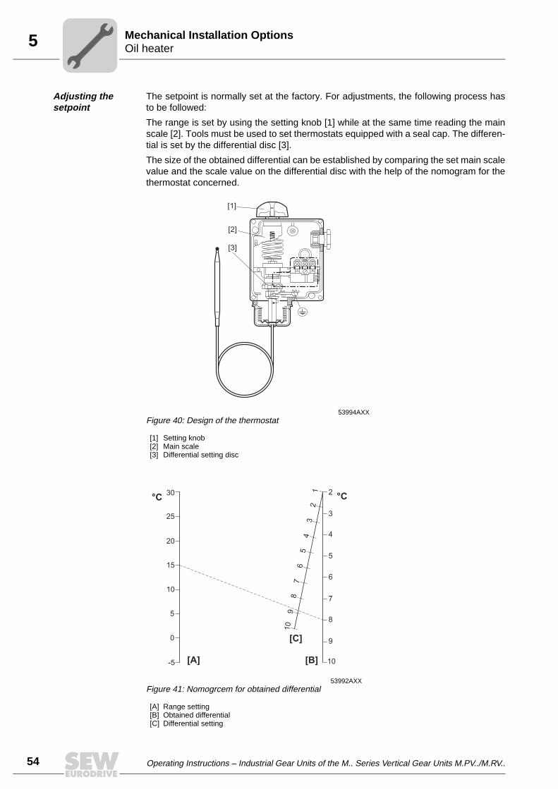
Adjusting the setpoint
The setpoint is normally set at the factory. For adjustments, the following process hasto be followed:
The range is set by using the setting knob [1] while at the same time reading the mainscale [2]. Tools must be used to set thermostats equipped with a seal cap. The differen-tial is set by the differential disc [3].
The size of the obtained differential can be established by comparing the set main scalevalue and the scale value on the differential disc with the help of the nomogram for thethermostat concerned.
53994AXXFigure 40: Design of the thermostat
[1] Setting knob[2] Main scale[3] Differential setting disc
53992AXXFigure 41: Nomogrcem for obtained differential
[A] Range setting[B] Obtained differential[C] Differential setting
12
4
[2]
[1]
[3]
°C °C
[C]
[B][A]
30
10
9
8
7
6
5
4
3
2
109
87
65
43
21
25
20
15
10
5
0
-5

Operating Instructions – Industrial Gear Units of the M.. Series Vertical Gear Units M.PV../M.RV.. 55
5Temperature sensor PT100Mechanical Installation Options
5.4 Temperature sensor PT100
The temperature sensor PT100 can be used to measure the temperature of the oil in thegear unit.
Dimensions
Electrical connection
Technical data • Sensor tolerance ± (0.3 + 0.005 × t), (corresponds to DIN IEC 751 class B), t = oil temperature
• Plug connector DIN 43650 PG9 (IP65)
• The tightening torque for the retaining screw in the back of the plug connector forelectrical connection is 25 Nm.
50533AXXFigure 42: Dimensions
24
Ø8
150
R1/2
35PG9, PG11
34
50534AXXFigure 43: Electrical connection
32 1

5
56 Operating Instructions – Industrial Gear Units of the M.. Series Vertical Gear Units M.PV../M.RV..
SPM adapterMechanical Installation Options
5.5 SPM adapter
SPM adapters are available for measuring the shock pulses of the gear unit bearings.Shock pulses are measured using shock pulse sensors attached to the SPM adapter.
Nipple 32000 and cover 81025
g = M8
L = 24, 113, 202, 291
Sensor to be wired 40000 and fitting 13008
g = M8
L = 17, 106, 195, 284
53871AXXFigure 44: SPM adapter
L11 17
g
Ø 1
1
53872AXXFigure 45: SPM adapter
L40
11 17
g
Ø 1
1

Operating Instructions – Industrial Gear Units of the M.. Series Vertical Gear Units M.PV../M.RV.. 57
5SPM adapterMechanical Installation Options
Mounting position of SPM - adapter
M.PV../M.RV..
Nipples [1], [2], [3] and [4] are on one side of the gear unit.
Nipple [5] only for M.RV.. gear units
Mounting of shock pulse sensor
• Remove the protection cap of the SPM adapter [1]. Ensure that the SPM adapter [1]is tightened correctly and securely (tightening torque: 15 Nm).
• Mount the shock pulse sensor [2] onto the SPM adapter [1].
54264AXXFigure 46: M2P.../M3R... Position SPM - adapter
[5]
[3]
[3]
[4][1]
51885AXFigure 47: Mounting the shock pulse sensor onto the SPM adapter
[1] SPM adapter[2] Pulse sensor
[1]
[2]

5
58 Operating Instructions – Industrial Gear Units of the M.. Series Vertical Gear Units M.PV../M.RV..
FanMechanical Installation Options
5.6 Fan
A fan can be mounted if the projected thermal power of the gear unit is exceeded. Thedirection of rotation of the gear unit does not influence the operation of the fan.
Typ M3RV..
53277AXXFigure 48: Fan
U4
FK1
X2
X1
Gear Unit Fan1 n1max U4 X1 X2 FK1min
M3RV30 ∅ 200 3000 758 450 371 15
M3RV40 ∅ 250 3000 821 504 423 15
M3RV50 ∅ 315 3000 995 590 491 20
M3RV60 ∅ 315 3000 1114 640 519 20
M3RV70 ∅ 400 2350 1269 740 607 20
M3RV80 ∅ 400 2350 1320 800 625 20
M3RV90 ∅ 400 2350 1493 846 652 20
1 Outer diameter of the fan
Make sure that air intake vents are not blocked or covered!

Operating Instructions – Industrial Gear Units of the M.. Series Vertical Gear Units M.PV../M.RV.. 59
6Shaft end pumpPressure Lubrication
6 Pressure Lubrication
6.1 Shaft end pump
The maintenance-free SHP shaft end pump [1] is suited for operation in both directionsof rotation.
M.V.. 10...50
M.V.. 60...90
The standard scope of delivery includes
• SHP (vertical) shaft end end pump [1]
• instrumentation version "IP" comprising
– visual pressure gauge (0...10 bars)– pressure switch
• piping and tube connections
For gear units equipped with a separate lubrication system (sometimes in connectionwith a cooling system), please also refer to the separate manual.
54267AXXFigure 49: Shaft end pump
[1]
54268AXXFigure 50: Shaft end pump
[1]
For operation with variable input speed, it is essential to consult SEW-EURODRIVE.
For a detailed description, refer to the separate manual.

6
60 Operating Instructions – Industrial Gear Units of the M.. Series Vertical Gear Units M.PV../M.RV..
Shaft end pumpPressure Lubrication
Pump suction The intake and delivery pipe or tube is connected disregarding the direction of rotationof the output shaft and must not be altered. If the shaft end pump does not build uppressure within 10 seconds after the gear unit has been started (→ Flow monitoring viaoil sight glass on the gear unit), do the following:
• Loosen the plug-in connection [1] next to the intake pipe / intake tube on the valvehousing. Fill the suction line [SUC] and the pump with oil.
• Turn the pump so that the gear pump is lubricated with oil.
• Make sure that the pump can create a vacuum in the suction line [SUC] so the oilflow can start.
51646AXXFigure 51: Shaft end pump
[1] Plug connector[SUC] Suction line[PRE] Pressure line
[1]
[1]S
UC
PR
E
• It is essential that the gear unit is sufficiently lubricated from the verybeginning!
• Do not change the diameter of the tube / pipe connection!
• Do not open the pressure line [PRE]!

Operating Instructions – Industrial Gear Units of the M.. Series Vertical Gear Units M.PV../M.RV.. 61
6Motor pumpPressure Lubrication
6.2 Motor pump
The MHP motor pump [1] is suited for operation in both directions of rotation.
The standard scope of delivery includes
• MHP motor pump comprising
– AC motor– coupling between AC motor and gear wheel pump– gear wheel pump
• instrumentation version "IP" comprising– visual pressure gauge (0...10 bars)– pressure switch
• piping and tube connections
• bracket installed on the gear unit to accommodate the motor pump.
AC motor:
Supply voltage: 220 V - 240 V / 380 V - 420 V, 50 Hz
Instrumentation IP
See shaft end pump
Other optional instruments (flow monitor, temperature monitor, ...) and optional equip-ment (oil filter, ...) are also available. Consult SEW-EURODRIVE.
6.3 External cooling system
For gear units supplied with an oil/water or oil/air cooling system, please refer to theseparate manual.
53884AXXFigure 52: Motor pump
[1]
Consult SEW-EURODRIVE in case of deviating supply voltages and/or 60 Hz operation.For a detailed description, please refer to the separate manual.

6
62 Operating Instructions – Industrial Gear Units of the M.. Series Vertical Gear Units M.PV../M.RV..
Customer supplied external cooling and lubrication systemsPressure Lubrication
6.4 Customer supplied external cooling and lubrication systems
Genaral If the customer orders a gear unit for which SEW-EURODRIVE recommends a pressurelubrication or/and an additional cooling system, this chapter provides some guidelinesfor selecting the components.
First, define
• the required oil volume QP the motor pump has to provide
• the required cooling capacity PL of the oil/water or oil/air cooler
Selecting the required oil flow for the oil pump QP
The minimum required oil flow QP can be selected from the following table:
If a cooling system has to be used, the required oil flow can be calculated with thefollowing formula:
QR = 2,3 × PL
with PL: Power losses to be cooled (→ "Selecting the cooling capacity of the cooler")
If the gear unit is ordered for a customer-supplied pressure lubrication system,the gear unit must not be taken into operation without the pressure lubricationsystem.
Required oil flow in ltr./min
Gear unit size M2PV ...M3PV...M3RV...
M4PV...M4RV...
10 6.3 7.5
20 6.9 8.3
30 8.4 10.0
40 9.6 11.5
50 11.0 13.2 15.3
60 12.8 15.2 17.7
70 14.5 17.3 20.2
80 15.9 19.0 22.1
90 17.5 20.9 24.3
QL determines the minimum required oil flow for pressure lubrication with or with-out cooler. If QR < QL, then QL has to be used as the required value for the oil flowQP

Operating Instructions – Industrial Gear Units of the M.. Series Vertical Gear Units M.PV../M.RV.. 63
6Customer supplied external cooling and lubrication systemsPressure Lubrication
Selecting the cooling capacity
QR = 2,3 × PL
QP ≥ QR
Choosing the cooling capacity of the oil cooler:
FL = 1.1 (clean) ... 1.2 (dirty cooling media)
PC ≥ FL × PL
We recommend to use the following additional components and instrumentation:
• Oil filter with a minimum filtration degree of 20 µm
• Control switch to check operation of the motor pump, for example using a pressureswitch
• If cooler is used: Control of oil temperature in the return line of ther cooler, forexample using a thermo switch or a visual thermometer
PL [kW] = power loss to be cooled PK1 [kW] = gear unit running loadPT [kW] = gear unit thermal rating (from catalog)η = gear unit efficiency
M2P η = 0.97M3P, M3R η = 0.955M4P, M4R η = 0.94
QR [ltr/min] = oil flow needed for cooling the gear unitQP [ltr/min] = oil pump output
PC [kW] = cooling rating (see tables 1.2 and 3)FL = safety factor for cooling capacity
P = ( ) PL K1
TP2
- (1 - η)x

6
64 Operating Instructions – Industrial Gear Units of the M.. Series Vertical Gear Units M.PV../M.RV..
Customer supplied external cooling and lubrication systemsPressure Lubrication
Typical setup pressure lubrication
Typical setup pressure lubrica-tion with oil/water cooler
53986AXXFigure 53: Pressure lubrication
[1] Motor pump[2] Filter[3] Pressure switch[4] Visual thermometer[5] Pressure relief valve[G] Gear unit
M
G
[1]
[2]
[3] [4]
[5]
53988AXXFigure 54: Pressure lubrication with oil/water cooler
[1] Motor pump[2] Filter[3] Oil/water cooler[4] Thermometer
[5] Pressure gauge[6] Pressure relief valve[7] Pressure switch[G] Gear unit
M
[1]
[2]
[7][3] [5] [4]
[6]
G

Operating Instructions – Industrial Gear Units of the M.. Series Vertical Gear Units M.PV../M.RV.. 65
6Customer supplied external cooling and lubrication systemsPressure Lubrication
Typical setup pressure lubrica-tion with oil/water cooler
53989AXXFigure 55: Setup of pressure lubrication with oil/water cooler
[1] Pump[2] Filter[3] Oil cooler[4] Thermo switch 50 °C[5] Thermometer[6] Pressure gauge[7] Pressure switch[G] Gear unit
M
[1]
[2]
[7][3] [5] [4]
[6]
M
G
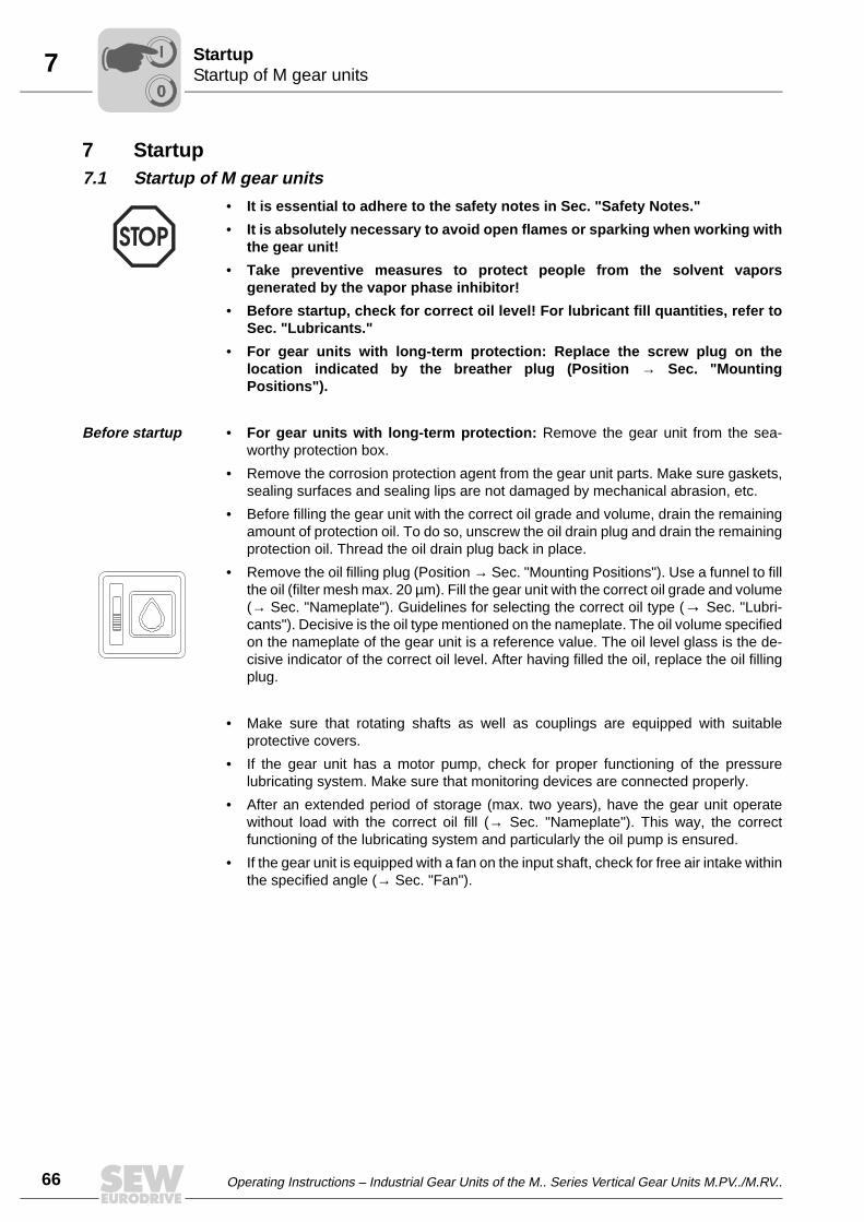
7
66 Operating Instructions – Industrial Gear Units of the M.. Series Vertical Gear Units M.PV../M.RV..
Startup of M gear unitsStartup
7 Startup7.1 Startup of M gear units
Before startup • For gear units with long-term protection: Remove the gear unit from the sea-worthy protection box.
• Remove the corrosion protection agent from the gear unit parts. Make sure gaskets,sealing surfaces and sealing lips are not damaged by mechanical abrasion, etc.
• Before filling the gear unit with the correct oil grade and volume, drain the remainingamount of protection oil. To do so, unscrew the oil drain plug and drain the remainingprotection oil. Thread the oil drain plug back in place.
• Remove the oil filling plug (Position → Sec. "Mounting Positions"). Use a funnel to fillthe oil (filter mesh max. 20 µm). Fill the gear unit with the correct oil grade and volume(→ Sec. "Nameplate"). Guidelines for selecting the correct oil type (→ Sec. "Lubri-cants"). Decisive is the oil type mentioned on the nameplate. The oil volume specifiedon the nameplate of the gear unit is a reference value. The oil level glass is the de-cisive indicator of the correct oil level. After having filled the oil, replace the oil fillingplug.
• Make sure that rotating shafts as well as couplings are equipped with suitableprotective covers.
• If the gear unit has a motor pump, check for proper functioning of the pressurelubricating system. Make sure that monitoring devices are connected properly.
• After an extended period of storage (max. two years), have the gear unit operatewithout load with the correct oil fill (→ Sec. "Nameplate"). This way, the correctfunctioning of the lubricating system and particularly the oil pump is ensured.
• If the gear unit is equipped with a fan on the input shaft, check for free air intake withinthe specified angle (→ Sec. "Fan").
• It is essential to adhere to the safety notes in Sec. "Safety Notes."
• It is absolutely necessary to avoid open flames or sparking when working withthe gear unit!
• Take preventive measures to protect people from the solvent vaporsgenerated by the vapor phase inhibitor!
• Before startup, check for correct oil level! For lubricant fill quantities, refer toSec. "Lubricants."
• For gear units with long-term protection: Replace the screw plug on thelocation indicated by the breather plug (Position → Sec. "MountingPositions").
00
I

Operating Instructions – Industrial Gear Units of the M.. Series Vertical Gear Units M.PV../M.RV.. 67
7Startup of M gear units with backstopStartup
Running-in period
SEW-EURODRIVE recommends running-in the gear unit as first startup phase.Increase load and revolutions in two to three steps up to maximum level. The running-in phase takes about 10 hours.
Check the following points during the running-in phase:
• Verify the power values specified on the nameplate because their frequency may bea decisive factor for the service life of the gear unit.
• Does the gear unit run smoothly?
• Are there vibrations or unusual running noise?
• Are there signs of oil leakages on the gear unit?
7.2 Startup of M gear units with backstop
7.3 Startup of M gear units with steel oil expansion tanks
Oil filling must be carried out with care to avoid that any air is left in the gear unit. Beforefilling the gear unit with oil, the membrane in the steel expansion tank must be in downposition. During operation of the gear unit, the membrane moves up and down due tothe thermal expansion of the oil.
Position of the membrane before startup:
If air gets under the membrane in the steel oil expansion tank, it can move themembrane upward thus causing pressure in the gear unit and possibly oil leakage.
For further information and troubleshooting, refer to Sec. "Malfunctions".
For gear units with backstop, make sure the direction of rotation of the motor iscorrect!
52727AXXFigure 56: Position of the membrane before startup
[1] Oil level
[2] Membrane in down position
[3] Air
[1][2]
[3]
00
I

7
68 Operating Instructions – Industrial Gear Units of the M.. Series Vertical Gear Units M.PV../M.RV..
Startup of M gear units with steel oil expansion tanksStartup
The oil must have ambient temperature when filling the gear unit and the gear unit mustbe installed in its final mounting position. If the gear unit is filled before installation, thegear unit must not be tilted during installation to avoid that oil pushes the membraneupward.
1. Open the air outlet screw [6].
2. Open ALL upper screw plugs (usually two to three screw plugs) of the gear unit, suchas breather plug, oil filling plug and oil dipstick (optional).
3. Blow compressed air into the oil expansion tank through the breather plug [2]. Themembrane goes down (sometimes audibly).
4. Fill oil through the filling plug.
5. When the oil reaches the screw plug openings, re-install the screw plugs on thehousing.
6. Fill the gear unit until oil comes out from the air outlet screw [6]. Close the air outletscrew.
7. Fill oil level to the oil sight glass [4].
8. Check the oil level via oil sight glass to ensure that the oil level keeps stable. Themarks on the oil sight glass are decisive for the oil level. Fill more oil if required.
9. Screw in the oil dipstick (optional).
10.Carry out a test run to ensure that the oil level does not fall below the oil sight glass.
11.Check the oil level only when the gear unit has cooled off to ambient temperature.
53885AXXFigure 57: M.PVSF../M.RVSF.. industrial gear unit with steel oil expansion tank
[1] Steel oil expansion [4] Oil sight glass
[2] Breather [5] Oil drain plug
[3] Oil filling plug [6] Air outlet screw
[5]
[4]
[3]
[1] [2]
[6][6]
00
I

Operating Instructions – Industrial Gear Units of the M.. Series Vertical Gear Units M.PV../M.RV.. 69
7Taking M gear units out of operationStartup
7.4 Taking M gear units out of operation
If the gear unit is not operated for a longer period of time, you must activate it at regularintervals every two to three (2 to 3) weeks.
If the gear unit is not operated for a period longer than six (6) months, additionalcorrosion protection is required:
• Corrosion protection for the inside of gear units with splash lubrication or bathlubrication:
Fill the gear unit up to the breather plug with the oil grade specified on the nameplate.
• Corrosion protection for the inside of gear units with oil pressure lubrication:
Contact SEW-EURODRIVE in this case!
• Surface corrosion protection:
Apply a wax-based protective coating onto shaft ends and unpainted surfaces ascorrosion protection. Grease the sealing lips of the oil seal to protect them frompreservative agents.
Disconnect the drive from voltage supply and secure it to prevent unintentionalrestart!
For taking the gear unit back into operation, refer → Sec. "Startup".
00
I

8
70 Operating Instructions – Industrial Gear Units of the M.. Series Vertical Gear Units M.PV../M.RV..
Inspection and maintenance intervalsInspection and Maintenance
8 Inspection and Maintenance8.1 Inspection and maintenance intervals
Interval What to do?
• Daily
• Check the housing temperature:– with mineral oil: max. 80 °C– with synthetic oil: max. 90 °C
• Check gear unit noise• Check the gear unit for signs of leakage
• After 500 - 800 hours of operation • First oil change after initial startup
• After 500 hours of operation • Check the oil level, refill oil (→ Sec. "Nameplate") if neces-sary
• Every 3000 hours of operation, at least every 6 months
• Check the oil: If the gear unit is operated outdoors or in humid conditions, check the water content of the oil. The water content must not exceed 0.05 % (500 ppm).
• Fill labyrinth seals with grease. Use about 30 g grease per grease nipple.
• Clean the breather plug
• Depending on the operating conditions, at the latest every 12 months
• Change the mineral oil (→ Sec. "Inspection and mainte-nance of the gear unit")
• Check whether retaining screws are tightly secured• Check contamination and condition of the oil/air cooling
system• Check the condition of the oil/water cooling system• Clean oil filter, replace filter element if necessary
• Depending on the operating condi-tions, at the latest every 3 years
• Change synthetic oil (→ Sec. "Inspection and maintenance of the gear unit")
• Varying (depending on external factors)
• Repair or renew the surface/anticorrosion coating• Clean the gearcase surface and fan• Check the oil heater:
• Are all connection cables and terminals tightened securely and free from corrosion?
• Clean incrusted elements (such as the heating element) and replace, if required (→ Sec. "Inspection and main-tenance of the gear unit")

Operating Instructions – Industrial Gear Units of the M.. Series Vertical Gear Units M.PV../M.RV.. 71
8Lubricant change intervalsInspection and Maintenance
8.2 Lubricant change intervals
Change the oil more frequently when operating the industrial gear unit under moresevere/aggressive environmental conditions!
Mineral CLP lubricants and synthetic polyalphaolefin-based (PAO) lubricants are usedfor lubrication. The synthetic lubricant CLP HC (according to DIN 51502) shown in thefollowing figure corresponds to the PAO oils.
54506AXXFigure 58: Lubricant change intervals for M gear units under normal ambient conditions
[1] Hours of operation[2] Sustained oil bath temperature • Average value per oil type at 70 °C
[2]
[1]

8
72 Operating Instructions – Industrial Gear Units of the M.. Series Vertical Gear Units M.PV../M.RV..
Inspection and maintenance of the gear unitInspection and Maintenance
8.3 Inspection and maintenance of the gear unit
Checking the oil level
1. Disconnect the motor from voltage supply and secure it to preventunintentional restart!
Wait until the gear unit has cooled off – Danger of burns!
2. For gear units with oil level glass: Visually check correct oil level (= middle of oil sightglass)
3. For gear units with oil dipstick (option):
• Unscrew the oil dipstick and remove it. Clean the dipstick and re-insert it into thegear unit (do not screw in tightly!).
• Remove dipstick again and check oil level. Correct if necessary: the oil level iscorrect when it is between the oil level mark (= maximum oil level) and the end ofthe dipstick (= minimum oil level)
Checking the oil 1. Disconnect the motor from voltage supply and secure it to preventunintentional restart!
Wait until the gear unit has cooled off – Danger of burns!
2. Remove some oil from the oil drain plug
3. Check the oil consistency
– Viscosity– If you can see that the oil is heavily contaminated, we recommend to change the
oil disregarding the service intervals specified in Sec. "Service and maintenanceintervals".
• Do not mix different synthetic lubricants and do not mix synthetic with minerallubricants!
• For positions of the oil level plug, the drain plug, the breather plug and the oilsight glass, refer to Sec. "Mounting Positions."
MINMINMAXMAX
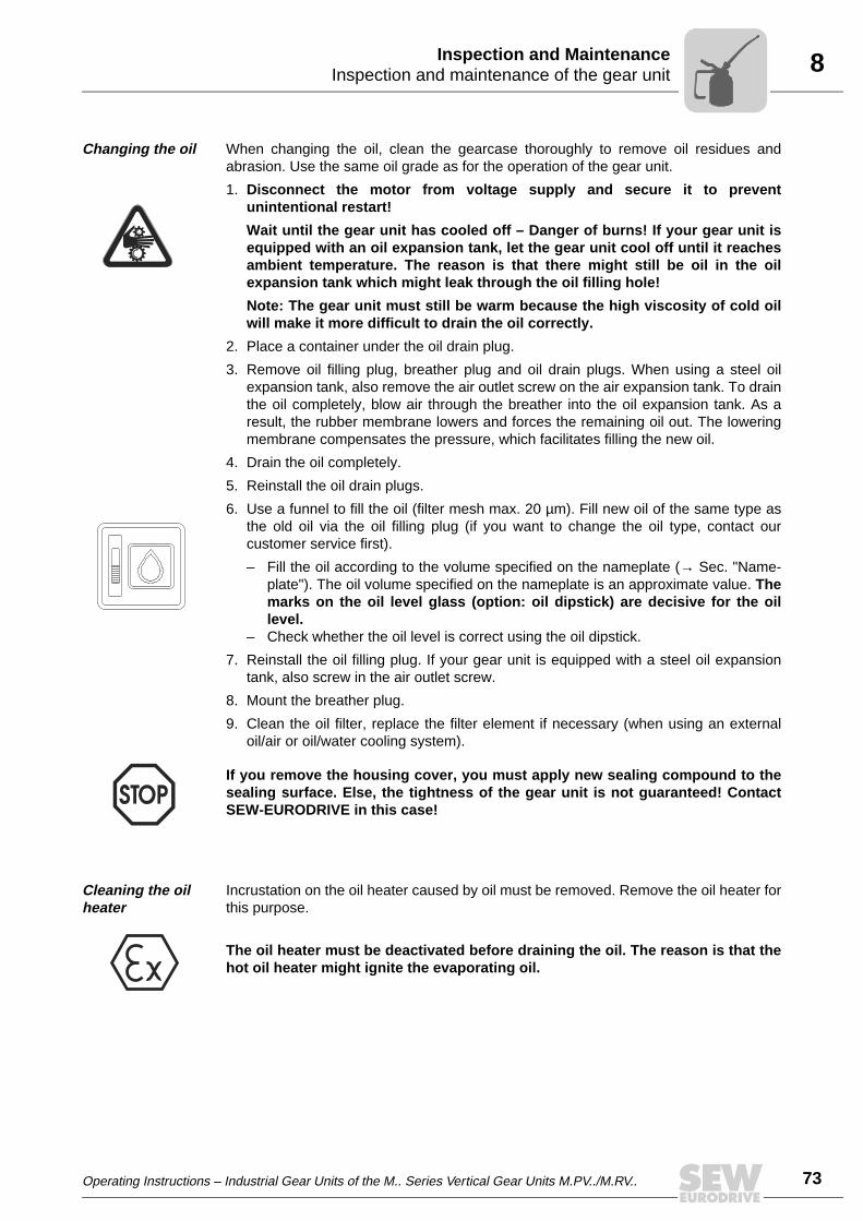
Operating Instructions – Industrial Gear Units of the M.. Series Vertical Gear Units M.PV../M.RV.. 73
8Inspection and maintenance of the gear unitInspection and Maintenance
Changing the oil When changing the oil, clean the gearcase thoroughly to remove oil residues andabrasion. Use the same oil grade as for the operation of the gear unit.
1. Disconnect the motor from voltage supply and secure it to preventunintentional restart!
Wait until the gear unit has cooled off – Danger of burns! If your gear unit isequipped with an oil expansion tank, let the gear unit cool off until it reachesambient temperature. The reason is that there might still be oil in the oilexpansion tank which might leak through the oil filling hole!
Note: The gear unit must still be warm because the high viscosity of cold oilwill make it more difficult to drain the oil correctly.
2. Place a container under the oil drain plug.
3. Remove oil filling plug, breather plug and oil drain plugs. When using a steel oilexpansion tank, also remove the air outlet screw on the air expansion tank. To drainthe oil completely, blow air through the breather into the oil expansion tank. As aresult, the rubber membrane lowers and forces the remaining oil out. The loweringmembrane compensates the pressure, which facilitates filling the new oil.
4. Drain the oil completely.
5. Reinstall the oil drain plugs.
6. Use a funnel to fill the oil (filter mesh max. 20 µm). Fill new oil of the same type asthe old oil via the oil filling plug (if you want to change the oil type, contact ourcustomer service first).
– Fill the oil according to the volume specified on the nameplate (→ Sec. "Name-plate"). The oil volume specified on the nameplate is an approximate value. Themarks on the oil level glass (option: oil dipstick) are decisive for the oillevel.
– Check whether the oil level is correct using the oil dipstick.
7. Reinstall the oil filling plug. If your gear unit is equipped with a steel oil expansiontank, also screw in the air outlet screw.
8. Mount the breather plug.
9. Clean the oil filter, replace the filter element if necessary (when using an externaloil/air or oil/water cooling system).
Cleaning the oil heater
Incrustation on the oil heater caused by oil must be removed. Remove the oil heater forthis purpose.
If you remove the housing cover, you must apply new sealing compound to thesealing surface. Else, the tightness of the gear unit is not guaranteed! ContactSEW-EURODRIVE in this case!
The oil heater must be deactivated before draining the oil. The reason is that thehot oil heater might ignite the evaporating oil.

8
74 Operating Instructions – Industrial Gear Units of the M.. Series Vertical Gear Units M.PV../M.RV..
Inspection and maintenance of the gear unitInspection and Maintenance
Removing the oil heater
• Remove the oil heater [1] and the gasket on the gear unit.
• Remove the base of the terminal box.
• Clean the tubular heating elements with solvent.
Mounting the oil heater
• Reinstall the oil heater [1] and the gasket on the gear unit. The tubular heatingelements must always be immersed in liquid.
• Mount the base of the terminal box onto the heating rod using a mounting ring.
• Make sure that the gasket is placed correctly between terminal box and upper end ofthe heating element.
• Insert the temperature sensor [2] into the oil sump of the gear unit. Set the requiredtemperature on the thermostat [3].
Refilling grease You can use grease of NLGI2 consistency to grease the regreasable dust protectioncovers or labyrinth seals ("Taconite") attached to input and output shafts as option (→Sec. "Lubricants", "Sealing grease").
For the locations of regreasing points, refer to the order-specific dimension sheet. Useabout 30 g grease per grease nipple disregarding the position of regreasing points andgear unit size.
53878AXXFigure 59: Oil heater M.V.. vertical gear units
[1] Oil heater[2] Temperatur sensor[3] Thermostat
90
[1]
[2]
[3]
[1]
Be careful not to damage the heating elements through scratching or scraping!
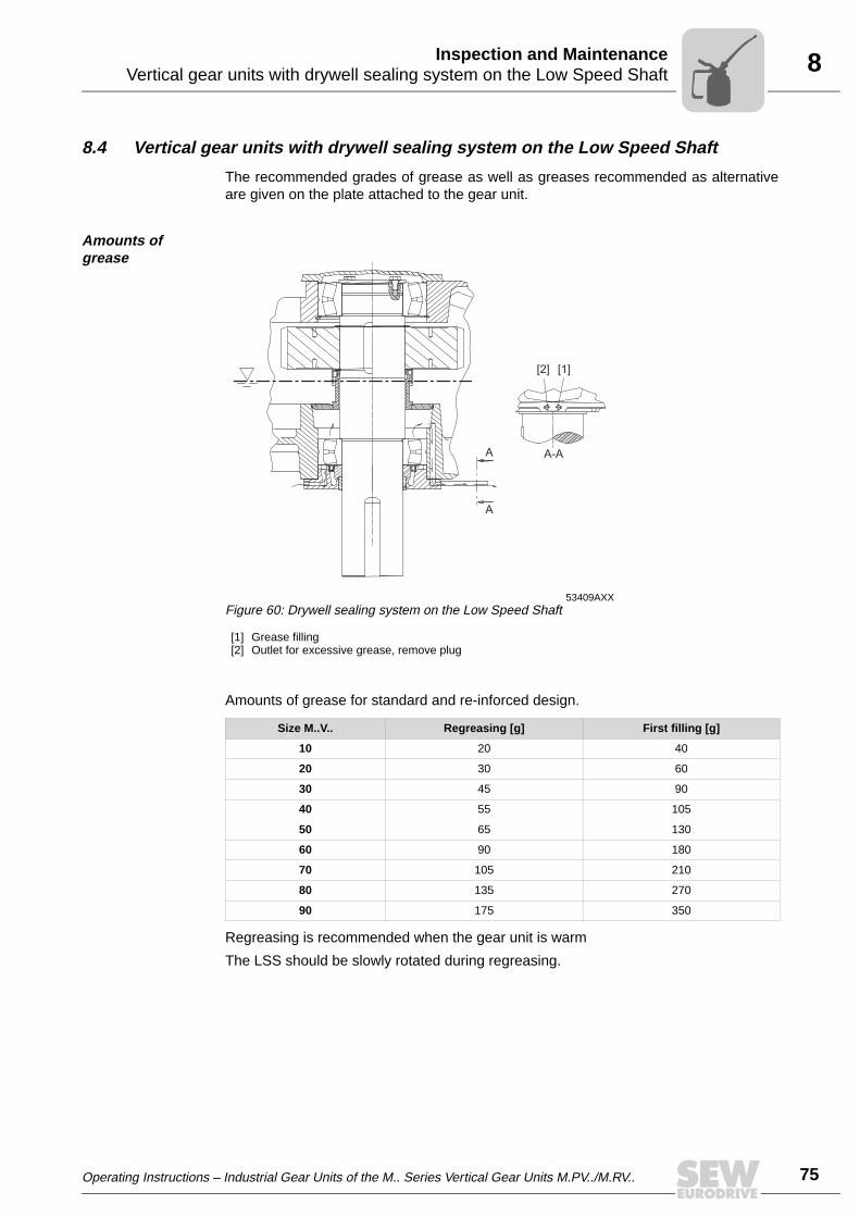
Operating Instructions – Industrial Gear Units of the M.. Series Vertical Gear Units M.PV../M.RV.. 75
8Vertical gear units with drywell sealing system on the Low Speed ShaftInspection and Maintenance
8.4 Vertical gear units with drywell sealing system on the Low Speed Shaft
The recommended grades of grease as well as greases recommended as alternativeare given on the plate attached to the gear unit.
Amounts of grease
Amounts of grease for standard and re-inforced design.
Regreasing is recommended when the gear unit is warm
The LSS should be slowly rotated during regreasing.
53409AXXFigure 60: Drywell sealing system on the Low Speed Shaft
[1] Grease filling[2] Outlet for excessive grease, remove plug
Size M..V.. Regreasing [g] First filling [g]
10 20 40
20 30 60
30 45 90
40 55 105
50 65 130
60 90 180
70 105 210
80 135 270
90 175 350
A-AA
A
[1][2]

8
76 Operating Instructions – Industrial Gear Units of the M.. Series Vertical Gear Units M.PV../M.RV..
Vertical gear units with drywell sealing system on the Low Speed ShaftInspection and Maintenance
Greasing intervals
Grease labels The label indicates the correct grease type. The number of grease nipples is marked inthe technical specification and on the nameplate, or on a separate plate.
53410AXXFigure 61: Greasing intervals for drywell system
Greasing interval [h] / LSS speed [r/min]
0500
1000
15002000250030003500400045005000
0 50 100 150 200 250 300LSS SPEED [r/min]
M..V..70..90
M..V..10..30
M..V..40..60
Ge ar
size

Operating Instructions – Industrial Gear Units of the M.. Series Vertical Gear Units M.PV../M.RV.. 77
9Gear unit malfunctionsMalfunctions
9 Malfunctions9.1 Gear unit malfunctions
Customer service
Problem Possible cause Solution
Unusual, regular running noise
A Meshing/grinding noise: bearing damageB Knocking noise: irregularity in the gearing
A Check the oil (→ Sec. "Inspection and Mainte-nance), replace bearings
B Contact customer service
Unusual, irregular running noise Foreign particles in the oil
• Check the oil (→ Sec. "Inspection and Mainte-nance")
• Stop the drive, contact customer service
Unusual noise in the area of the gear unit mounting Gear unit mounting has loosened
• Tighten the retaining screws and nuts to the specified torque
• Replace the damaged / defective retaining screws or nuts
Operating temperature too high
A Too much oilB Oil too oldC Oil contaminatedD Gear units with fan: air intake opening /
gearcase contaminatedE Shaft end pump defectiveF Malfunctions of oil/air or oil/water cooling
system
A Check the oil level, correct if necessary (→ Sec. "Inspection and Maintenance")
B Check when the oil was changed last time; change oil if necessary (→ Sec. "Inspection and Mainte-nance")
C Change the oil (→ Sec. "Inspection and Mainte-nance")
D Check the air intake opening and clean if necessary, clean gear unit housing
E Check the shaft end pump; replace if necessaryF Observe the separate operating instructions of the
oil/water and oil/air cooling system!
Bearing point temperatures too high
A Oil not enough or too much oilB Oil too oldC Shaft end pump defectiveD Bearing damaged
A Check the oil level, correct if necessary (→ Sec. "Inspection and Maintenance")
B Check when the oil was changed last time; change oil if necessary (→ Sec. "Inspection and Mainte-nance")
C Check the shaft end pump; replace if necessaryD Check bearing and replace if necessary, contact
customer service
Oil leaking1
• from cover plate• from gearcase cover• from bearing cover• from mounting flange• from output/input end oil
seal
1 It is normal for small amounts of oil/grease to emerge from the oil seal during the running-in phase (24 hour running time, see alsoDIN 3761).
A Gasket on cover plate / gearcase cover / bearing cover / mounting flange leaking
B Sealing lip of oil seal upside downC Oil seal damaged / worn
A Tighten the bolts on the respective cover plate and observe the gear unit. Oil still leaking: contact customer service
B Vent the gear unit (→ Sec. "Mounting Positions") Observe the gear unit. Oil still leaking: contact cus-tomer service
C Contact customer service
Oil leaking• from oil drain plug/valve• from breather plug
A Too much oilB Drive operated in incorrect mounting
positionC Frequent cold starts (oil foams) and/or
high oil level
A Correct the oil level (→ Sec. "Inspection and Main-tenance)
B Mount the breather plug correctly (→ Sec. "Mount-ing Positions") and correct the oil level (→ Sec. "Lubricants")
Malfunctions of the oil/air or oil/water cooling system
Observe separate operating instructions of the oil/water and oil/air cooling system!
Operating temperature at backstop too high Damaged / defective backstop • Check the backstop; replace if necessary
• Contact customer service
Please have the following information available when contacting our customer service:• Complete nameplate data• Nature and extent of the fault• Time of occurrence and accompanying circumstances of the fault• Presumed cause
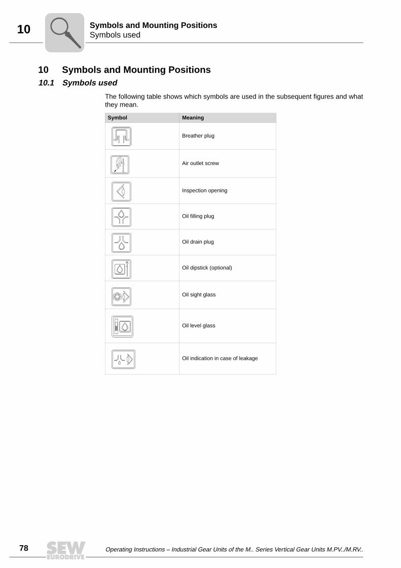
10
78 Operating Instructions – Industrial Gear Units of the M.. Series Vertical Gear Units M.PV../M.RV..
Symbols usedSymbols and Mounting Positions
10 Symbols and Mounting Positions10.1 Symbols used
The following table shows which symbols are used in the subsequent figures and whatthey mean.
Symbol Meaning
Breather plug
Air outlet screw
Inspection opening
Oil filling plug
Oil drain plug
Oil dipstick (optional)
Oil sight glass
Oil level glass
Oil indication in case of leakage

Operating Instructions – Industrial Gear Units of the M.. Series Vertical Gear Units M.PV../M.RV.. 79
10Mounting positions of M.PV.. gear unitsSymbols and Mounting Positions
10.2 Mounting positions of M.PV.. gear units
M.PV.. Bath lubrication
54213AXXFigure 62: M.PV.. Bath lubrication
54212AXXFigure 63: M.PV.. Bath lubrication
R11/2R11/2
R11/2R11/2

10
80 Operating Instructions – Industrial Gear Units of the M.. Series Vertical Gear Units M.PV../M.RV..
Mounting positions of M.PV.. gear unitsSymbols and Mounting Positions
M.PV.. Pressure lubrication
54216AXXFigure 64: M.PV.. Pressure lubrication
54217AXXFigure 65: M.PV.. Pressure lubrication

Operating Instructions – Industrial Gear Units of the M.. Series Vertical Gear Units M.PV../M.RV.. 81
10Mounting positions of M.PV.. gear unitsSymbols and Mounting Positions
M.RV.. Bath lubrication
54270AXXFigure 66: M.RV.. Bath lubrication
54507AXXFigure 67: M.RV.. Bath lubrication
R11/2R11/2
R11/2R11/2
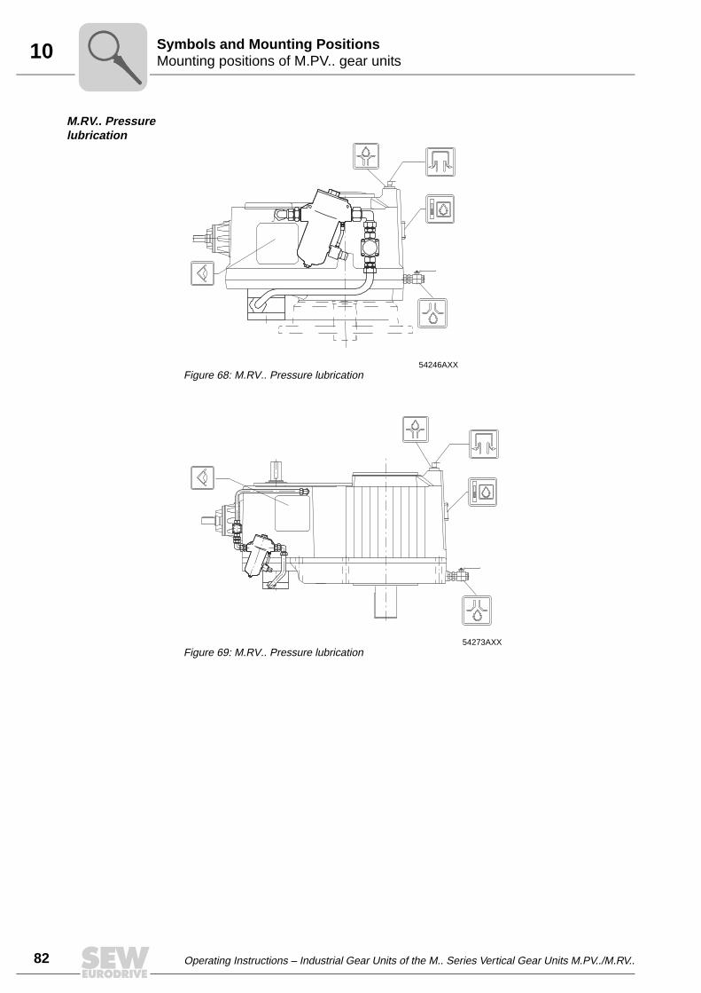
10
82 Operating Instructions – Industrial Gear Units of the M.. Series Vertical Gear Units M.PV../M.RV..
Mounting positions of M.PV.. gear unitsSymbols and Mounting Positions
M.RV.. Pressure lubrication
54246AXXFigure 68: M.RV.. Pressure lubrication
54273AXXFigure 69: M.RV.. Pressure lubrication

Operating Instructions – Industrial Gear Units of the M.. Series Vertical Gear Units M.PV../M.RV.. 83
11Guideline for oil and grease selectionLubricants
11 Lubricants11.1 Guideline for oil and grease selection
Lubricating oils This instruction applies to the following conditions:
• Ambient temperature in the range of –30 °C …+40 °C
• Actual max. pitch line velocity less than 35 m/s
• All lubricating methods with oil: splash, bath and pressure lubrication
In addition to the required viscosity class ISO VG, the oil must contain anti-wear, anti-rust, anti-oxidant and antifoam additives. The FZG stage should be at least 12 accordingto DIN 51354.
The oil must also contain EP additivies. If synthetic oils are selected due to operatingtemperatures or oil change intervals, SEW-EURODRIVE recommends polyalfaolefinbased (PAO) oil.
Mineral oils
Lubricating oil standards
Lubricating oils are grouped in ISO VG viscosity classes according to standards ISO 3448 and DIN 51519.
Containing EP additives
Selection of vis-cosity class ISO VG (40 °C)
The maximum operating temperature of mineral oil is 80 °C. Table 1 indicates therequired ISO VG class of the oil and the max. lubricating temperature TL of the oil.
Selection of the lubricating oil
Mineral oil (→ Tabel in sec. "Overview of lubricants for M.. industrial gear units/Minerallubricants")
When the gear unit is located outdoors, use an oil heater in the following cases:
• With splash or bath lubrication when the starting temperature is less than the pourpoint of the oil
• With pressure lubrication when the starting oil viscosity is greater than 2000 cSt.
ISO VG ISO 6743-6 DIN 51517-3 AGMA 9005-D94
class designation designation designation
150 ISO-L-CKC 150 DIN 51517 CLP 150 AGMA 4 EP
220 ISO-L-CKC 220 DIN 51517 CLP 220 AGMA 5 EP
320 ISO-L-CKC 320 DIN 51517 CLP 320 AGMA 6 EP
460 ISO-L-CKC 460 DIN 51517 CLP 460 AGMA 7 EP
680 ISO-L-CKC 680 DIN 51517 CLP 680 AGMA 8 EP
Pi
fkVA
Hz
n
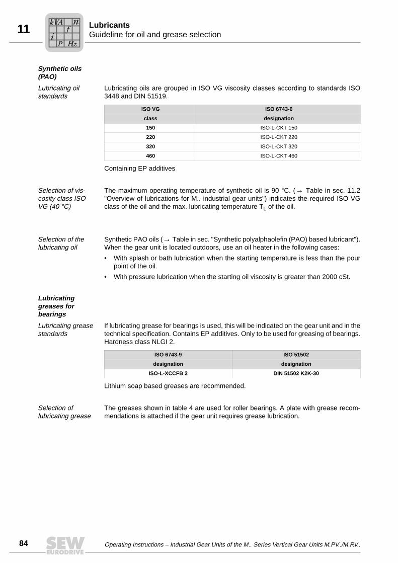
11
84 Operating Instructions – Industrial Gear Units of the M.. Series Vertical Gear Units M.PV../M.RV..
Guideline for oil and grease selectionLubricants
Synthetic oils (PAO)
Lubricating oil standards
Lubricating oils are grouped in ISO VG viscosity classes according to standards ISO3448 and DIN 51519.
Containing EP additives
Selection of vis-cosity class ISO VG (40 °C)
The maximum operating temperature of synthetic oil is 90 °C. (→ Table in sec. 11.2"Overview of lubrications for M.. industrial gear units") indicates the required ISO VGclass of the oil and the max. lubricating temperature TL of the oil.
Selection of the lubricating oil
Synthetic PAO oils (→ Table in sec. "Synthetic polyalphaolefin (PAO) based lubricant").When the gear unit is located outdoors, use an oil heater in the following cases:
• With splash or bath lubrication when the starting temperature is less than the pourpoint of the oil.
• With pressure lubrication when the starting oil viscosity is greater than 2000 cSt.
Lubricating greases for bearings
Lubricating grease standards
If lubricating grease for bearings is used, this will be indicated on the gear unit and in thetechnical specification. Contains EP additives. Only to be used for greasing of bearings.Hardness class NLGI 2.
Lithium soap based greases are recommended.
Selection of lubricating grease
The greases shown in table 4 are used for roller bearings. A plate with grease recom-mendations is attached if the gear unit requires grease lubrication.
ISO VG ISO 6743-6
class designation
150 ISO-L-CKT 150
220 ISO-L-CKT 220
320 ISO-L-CKT 320
460 ISO-L-CKT 460
ISO 6743-9 ISO 51502
designation designation
ISO-L-XCCFB 2 DIN 51502 K2K-30
Pi
fkVA
Hz
n

Operating Instructions – Industrial Gear Units of the M.. Series Vertical Gear Units M.PV../M.RV.. 85
11Guideline for oil and grease selectionLubricants
Slow speed gear units
When the pitch line velocity of the slowest stage is under 1 m/s (n2 < 15 1/min), the gearunit operates in boundary lubrication area.
It is recommended to use:
• mineral oils with EP- and anti-wear additives
• running viscosity should be ≥ 100 cSt
• the cleanliness of the oil and the oil sump must be ensured.
Oil selection, ISO VG (40 °C) class
TL = Max. lubricating temperature of the oil which lubricates the gearmeshes and bear-ings
Number of stages in the gear
unit
Splash or bath lubrication1
Pres. lubricationNO ext. cooler1
Pres. lubricationext. cooler,spray dose,
splash or bath lubrication2
Pres. lubricationext. cooler,
oil led togearmeshes and bearings3
Note
ISO VG (40 °C)
TL[°C]
ISO VG (40 °C)
TL[°C]
ISO VG (40 °C)
TL[°C]
ISO VG (40 °C)
TL[°C]
2 320 90 320 90 220 70 220 60 Synthetic oil
2 320 80 320 80 220 70 220 60 Mineral oil
3 460 80 460 80 320 70 320 60 Mineral oilSynthetic oil
4 460 70 460 70 460 70 320 60 ONLY mineral oil
5 460 70 460 70 460 70 320 60 ONLY mineral oil
1 The oil temperature TL is measured from the oil surface
2 The oil temperature going into the gear unit is different that lubricates the gearmeshes and bearings. NO direct piping to the gearmeshesand bearings is made. The oil temperature when going into the gear unit is set in the range of 45 °C …55 °C
3 The oil is led directly to the gearmeshes and bearings via direct piping. The oil temperature when going into the gear unit is set in therange of 45 °C … 55 °C
Pi
fkVA
Hz
n

11
86 Operating Instructions – Industrial Gear Units of the M.. Series Vertical Gear Units M.PV../M.RV..
Guideline for oil and grease selectionLubricants
Mineral oils
Synthetic PAO oils
53995AXXFigure 70: Mineral oils
[1] Oil temperature[2] Operating oil viscosity[3] Oil ISO VG viscosity class
100-10 10 20 30 40
150 320
220 460
680
50 60 70 80 90 100-20
40
100
1000
2000
3000
150200
500
cSt
°C[1]
[2]
[3]
53996AXXFigure 71: Synthetic PAO oils
[1] Oil temperature[2] Operating oil viscosity[3] Oil ISO VG viscosity class
100-10 10 20 30 40
150 320
220 460
50 60 70 80 90 100-20
40
100
1000
2000
3000
150200
500
°C
cSt
[1]
[2]
[3]
Pi
fkVA
Hz
n
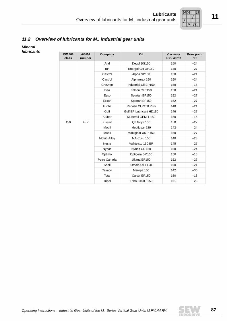
Operating Instructions – Industrial Gear Units of the M.. Series Vertical Gear Units M.PV../M.RV.. 87
11Overview of lubricants for M.. industrial gear unitsLubricants
11.2 Overview of lubricants for M.. industrial gear units
Mineral lubricants
ISO VGclass
AGMAnumber
Company Oil ViscositycSt / 40 °C
Pour point°C
150 4EP
Aral Degol BG150 150 –24
BP Energol GR-XP150 140 –27
Castrol Alpha SP150 150 –21
Castrol Alphamax 150 150 –24
Chevron Industrial Oil EP150 150 –15
Dea Falcon CLP150 150 –21
Esso Spartan EP150 152 –27
Exxon Spartan EP150 152 –27
Fuchs Renolin CLP150 Plus 148 –21
Gulf Gulf EP Lubricant HD150 146 –27
Klüber Klüberoil GEM 1-150 150 –15
Kuwait Q8 Goya 150 150 –27
Mobil Mobilgear 629 143 –24
Mobil Mobilgear XMP 150 150 –27
Molub-Alloy MA-814 / 150 140 –23
Neste Vaihteisto 150 EP 145 –27
Nynäs Nynäs GL 150 150 –24
Optimol Optigera BM150 150 –18
Petro Canada Ultima EP150 152 –27
Shell Omala Oil F150 150 –21
Texaco Meropa 150 142 –30
Total Carter EP150 150 –18
Tribol Tribol 1100 / 150 151 –28
Pi
fkVA
Hz
n

11
88 Operating Instructions – Industrial Gear Units of the M.. Series Vertical Gear Units M.PV../M.RV..
Overview of lubricants for M.. industrial gear unitsLubricants
220 5EP
Aral Degol BG220 220 –21
BP Energol GR-XP220 210 –27
Castrol Alpha SP220 220 –21
Castrol Alphamax 220 220 –24
Chevron Industrial Oil EP220 220 –12
Dea Falcon CLP220 220 –18
Esso Spartan EP220 226 –30
Exxon Spartan EP220 226 –30
Fuchs Renolin CLP220 Plus 223 –23
Gulf Gulf EP Lubricant HD220 219 –19
Klüber Klüberoil GEM 1-220 220 –15
Kuwait Q8 Goya 220 220 –21
Mobil Mobilgear 630 207 –18
Mobil Mobilgear XMP 220 220 –24
Molub-Alloy MA-90 / 220 220 –18
Neste Vaihteisto 220 EP 210 –27
Nynäs Nynäs GL 220 220 –18
Optimol Optigear BM220 233 –15
Petro Canada Ultima EP220 223 –30
Shell Omala Oil F220 220 –21
Texaco Meropa 220 209 –21
Total Carter EP220 220 –12
Tribol Tribol 1100 / 220 222 –25
ISO VGclass
AGMAnumber
Company Oil ViscositycSt / 40 °C
Pour point°C
Pi
fkVA
Hz
n
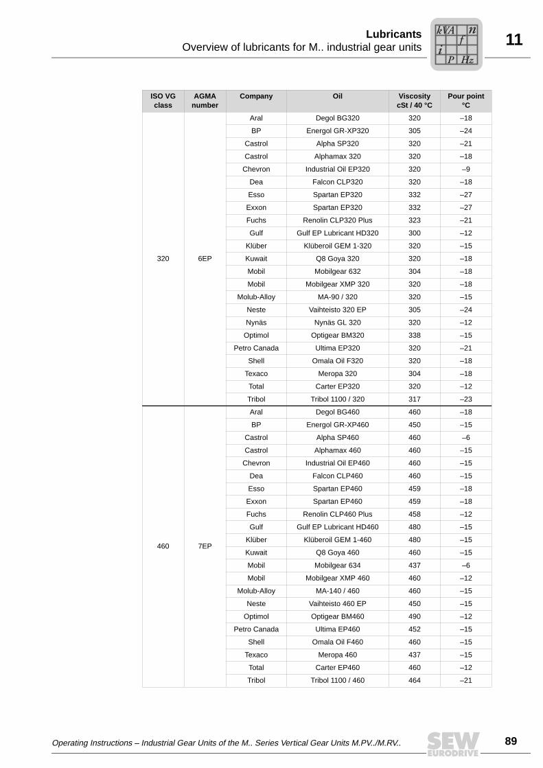
Operating Instructions – Industrial Gear Units of the M.. Series Vertical Gear Units M.PV../M.RV.. 89
11Overview of lubricants for M.. industrial gear unitsLubricants
ISO VGclass
AGMAnumber
Company Oil ViscositycSt / 40 °C
Pour point°C
320 6EP
Aral Degol BG320 320 –18
BP Energol GR-XP320 305 –24
Castrol Alpha SP320 320 –21
Castrol Alphamax 320 320 –18
Chevron Industrial Oil EP320 320 –9
Dea Falcon CLP320 320 –18
Esso Spartan EP320 332 –27
Exxon Spartan EP320 332 –27
Fuchs Renolin CLP320 Plus 323 –21
Gulf Gulf EP Lubricant HD320 300 –12
Klüber Klüberoil GEM 1-320 320 –15
Kuwait Q8 Goya 320 320 –18
Mobil Mobilgear 632 304 –18
Mobil Mobilgear XMP 320 320 –18
Molub-Alloy MA-90 / 320 320 –15
Neste Vaihteisto 320 EP 305 –24
Nynäs Nynäs GL 320 320 –12
Optimol Optigear BM320 338 –15
Petro Canada Ultima EP320 320 –21
Shell Omala Oil F320 320 –18
Texaco Meropa 320 304 –18
Total Carter EP320 320 –12
Tribol Tribol 1100 / 320 317 –23
460 7EP
Aral Degol BG460 460 –18
BP Energol GR-XP460 450 –15
Castrol Alpha SP460 460 –6
Castrol Alphamax 460 460 –15
Chevron Industrial Oil EP460 460 –15
Dea Falcon CLP460 460 –15
Esso Spartan EP460 459 –18
Exxon Spartan EP460 459 –18
Fuchs Renolin CLP460 Plus 458 –12
Gulf Gulf EP Lubricant HD460 480 –15
Klüber Klüberoil GEM 1-460 480 –15
Kuwait Q8 Goya 460 460 –15
Mobil Mobilgear 634 437 –6
Mobil Mobilgear XMP 460 460 –12
Molub-Alloy MA-140 / 460 460 –15
Neste Vaihteisto 460 EP 450 –15
Optimol Optigear BM460 490 –12
Petro Canada Ultima EP460 452 –15
Shell Omala Oil F460 460 –15
Texaco Meropa 460 437 –15
Total Carter EP460 460 –12
Tribol Tribol 1100 / 460 464 –21
Pi
fkVA
Hz
n

11
90 Operating Instructions – Industrial Gear Units of the M.. Series Vertical Gear Units M.PV../M.RV..
Overview of lubricants for M.. industrial gear unitsLubricants
ISO VGclass
AGMAnumber
Company Oil ViscositycSt / 40 °C
Pour point°C
680 8EP
Aral Degol BG680 680 –12
BP Energol GR-XP680 630 –9
Castrol Alpha SP680 680 –6
Dea Falcon CLP680 680 –12
Esso Spartan EP680 677 –15
Exxon Spartan EP680 677 –15
Fuchs Renolin CLP680 Plus 671 –15
Gulf Gulf EP Lubricant HD680 680 –12
Klüber Klüberoil GEM 1-680 680 –12
Kuwait Q8 Goya 680 680 –9
Mobil Mobilgear 636 636 –6
Mobil Mobilgear XMP 680 680 –9
Molub-Alloy MA-170W / 680 680 –12
Neste Vaihteisto 680 EP 630 –9
Optimol Optigear BM680 680 –9
Petro Canada Ultima EP680 680 –9
Statoil Loadway EP 680 645 –9
Texaco Meropa 680 690 –12
Total Carter EP680 680 –9
Tribol Tribol 1100 / 680 673 –21
Pi
fkVA
Hz
n

Operating Instructions – Industrial Gear Units of the M.. Series Vertical Gear Units M.PV../M.RV.. 91
11Overview of lubricants for M.. industrial gear unitsLubricants
Synthetic polyalphaolefin (PAO) based lubricant
The synthetic polyalphaolefin-based lubricants correspond to the CLP HC oils(according to DIN 51502).
ISO VGclass
AGMAnumber
Company Oil ViscositycSt
Pour point°C
40 °C 100 °C
150 4EP
Dea Intor HCLP150 150 19.8 –36
Fuchs Renolin Unisyn CLP150 151 19.4 –39
Klüber Klübersynth EG 4-150 150 19 –45
Mobil Mobilgear SHC XMP150 150 21.2 –48
Shell Omala Oil HD150 150 22.3 –45
Texaco Pinacle EP150 150 19.8 –50
Total Carter EP / HT150 150 19 –42
Tribol Tribol 1510 / 150 155 18.9 –45
220 5EP
Dea Intor HCLP 220 220 25.1 –36
Esso Spartan Synthetic EP220 232 26.5 –39
Exxon Spartan Synthtic EP220 232 26.5 –39
Fuchs Renolin Unisyn CLP220 221 25.8 –42
Klüber Klübersynth EG 4-220 220 26 –40
Mobil Mobilgear SHC XMP220 220 28.3 –45
Mobil Mobilgear SHC220 213 26 –51
Optimol Optigear Synthic A220 210 23.5 –36
Shell Omala Oil HD220 220 25.5 –48
Texaco Pinnacle EP220 220 25.8 –48
Total Carter EP / HT220 220 25 –39
Tribol Tribol 1510 / 220 220 24.6 –42
Tribol Tribol 1710 / 220 220 - –33
320 6EP
Dea Intor HCLP 320 320 33.9 –33
Esso Spartan Synthetic EP320 328 34.3 –36
Exxon Spartan Synthtic EP320 328 34.3 –36
Fuchs Renolin Unisyn CLP320 315 33.3 –39
Klüber Klübersynth EG 4-320 320 38 –40
Mobil Mobilgear SHC XMP320 320 37.4 –39
Mobil Mobilgear SHC320 295 34 –48
Optimol Optigear Synthic A320 290 30 –36
Shell Omala Oil HD320 320 33.1 –42
Texaco Pinnacle EP320 320 35.2 –39
Total Carter EP / HT320 320 33 –36
Tribol Tribol 1510 / 320 330 33.2 –39
Tribol Tribol 1710 / 320 320 - –30
Pi
fkVA
Hz
n

11
92 Operating Instructions – Industrial Gear Units of the M.. Series Vertical Gear Units M.PV../M.RV..
Sealing greaseLubricants
11.3 Sealing grease
SEW-EURODRIVE recommends the grease types listed in below table for operatingtemperatures from – 30 °C to +100 °C.
ISO VGclass
AGMAnumber
Company Oil ViscositycSt
Pour point°C
40 °C 100 °C
460 7EP
Dea Intor HCLP 460 460 45 –33
Esso Spartan Synthetic EP460 460 44.9 –33
Exxon Spartan Synthtic EP460 460 44.9 –33
Fuchs Renolin Unisyn CLP460 479 45 –33
Klüber Klübersynth EG 4-460 460 48 –35
Mobil Mobilgear SHC XMP460 460 48.5 –36
Mobil Mobilgear SHC460 445 46 –45
Optimol Optigear Synthic A460 463 44.5 –30
Shell Omala Oil HD460 460 45.6 –39
Texaco Pinnacle EP460 460 47.2 –39
Total Carter EP / HT460 460 44 –33
Tribol Tribol 1510 / 460 460 43.7 –33
Tribol Tribol 1710 / 460 460 - –30
Company Oil Penetration NLGI 2 (EP)Drop point °C
Aral Aralub HLP2 265/295 180
BP Energrease LS-EPS 265/295 190
Castrol Spheerol EPL2 265/295 175
Chevron Dura-Lith EP2 265/295 185
Elf Epexa EP2 265/295 180
Esso Beacon EP2 270/280 185
Exxon Beacon EP2 270/280 185
Gulf Gulf crown Grease 2 279/290 193
Klüber Centoplex EP2 265/295 190
Kuwait Q8 Rembrandt EP2 265/295 180
Mobil Mobilux EP2 265/295 177
Molub Alloy BRB-572 240/270 188
Optimol Olista Longtime 2 265/295 180
Shell Alvania EP2 265/295 180
Texaco Multifak EP2 265/295 186
Total Multis EP2 265/295 190
Tribol Tribol 3030-2 265/295 182
Pi
fkVA
Hz
n

Operating Instructions – Industrial Gear Units of the M.. Series Vertical Gear Units M.PV../M.RV.. 93
11Lubricant fill quantitiesLubricants
11.4 Lubricant fill quantities
The specified fill quantities are guide values. The precise values vary depending on thegear ratio.
M.PV..
M.RV..
Gear unit size M.PV..
Lubrication type
Oil volume [l]
Two stages Three stages Four stages
M2PV.. M3PV.. M4PV..
10 BathPressure
3414
3313
20 BathPressure
3916
3815
30 BathPressure
6825
6624
40 BathPressure
9434
9233
50 BathPressure
15251
15050
14849
60 BathPressure
18361
18060
17759
70 BathPressure
26386
26085
25784
80 BathPressure
353122
350120
347118
90 BathPressure
450150
446148
Gear unit size M.RV..
Lubrication type
Oil volume [l]
Three stages Four stages
M3RV.. M4RV..
30 BathPressure
6624
40 BathPressure
9233
50 BathPressure
15050
14849
60 BathPressure
18060
17759
70 BathPressure
26085
25784
80 BathPressure
350120
347118
90 BathPressure
450150
446148
When using pressure lubrication, it is essential to observe the specifications on thenameplate and in the order-specific documentation!
Pi
fkVA
Hz
n
94 Operating Instructions - Industrial Gear Units of the M.. Series Vertical Gear Units M.PV../M.RV..
Index
IndexCChanging the oil ..................................................73Checking the oil ..................................................72Checking the oil level ..........................................72Concrete base .....................................................24Corrision protection ...............................................7
DDesignated use .....................................................5Directions of rotation ...........................................13Drywell ................................................................75
EExternal cooling system ......................................61
FFan ......................................................................58
GGear unit design ....................................................9Gear unit foundation ...........................................23Gear unit malfunctions ........................................77Grouting ..............................................................26
IInspection and maintenance of the gear unit ......72
changing the oil ............................................73checking the oil .............................................72checking the oil level ....................................72cleaning the oil heater ..................................73refilling grease ..............................................74
Inspection intervals .............................................70installation notes .................................................39Installation tolerances .........................................22
LLubricant change intervals ..................................71Lubricants ...........................................................83
Overview of lubricant fill quantities ...............93Overview of mineral lubricants .....................87Overview of sealing grease ..........................92Overview of synthetic lubricants ...................91
Lubrication of industrial gear units ......................19
MMaintenance .......................................................70Maintenance intervals .........................................70Malfunctions
possible cause ..............................................77Solution .........................................................77
malfunctions ........................................................77Mechanical Installation ........................................22Mechanical Installation Options ..........................39Motor pump .........................................................61Mounting a motor with motor adapter .................38Mounting of couplings .........................................42
GM, GMD, GMX coupling .............................48
Nor-Mex coupling (types G, E) .................... 44ROTEX coupling .......................................... 42
Mounting of hollow shaft gear units with keyed con-nection ................................................................ 30Mounting of hollow shaft gear units with shrink disc 33Mounting of solid shaft gear units ...................... 28
NNameplates ........................................................ 12
OOil bath lubrication ............................................. 19Oil expansion tank made from steel ................... 19Oil heater ............................................................ 50Ölausgleichsbehälter aus Grauguss .................. 20
PPressure lubrication ..................................... 21, 59
SSafety Notes ......................................................... 5Shaft end pump SHP ......................................... 59shaft positions .................................................... 13SPM adapter ...................................................... 56
Mounting of shock pulse sensor .................. 57Mounting positions ....................................... 57
Startup ................................................................ 66Gear units with backstop ............................. 67Running-in period ........................................ 67
Storage conditions ............................................... 7
TTaking MC.. gear units out of operation ............. 69Temperature sensor PT100 ............................... 55Transport of industrial gear units .......................... 6
UUnit designation ................................................. 11

Address List
07/2004 95
Address ListGermany
HeadquartersProductionSales
Bruchsal SEW-EURODRIVE GmbH & Co KGErnst-Blickle-Straße 42 D-76646 BruchsalP.O. BoxPostfach 3023 · D-76642 Bruchsal
Tel. +49 7251 75-0Fax +49 7251 75-1970http://[email protected]
Service Competence Center
Central Gear units / Motors
SEW-EURODRIVE GmbH & Co KGErnst-Blickle-Straße 1 D-76676 Graben-Neudorf
Tel. +49 7251 75-1710Fax +49 7251 [email protected]
Central Electronics
SEW-EURODRIVE GmbH & Co KGErnst-Blickle-Straße 42 D-76646 Bruchsal
Tel. +49 7251 75-1780Fax +49 7251 [email protected]
North SEW-EURODRIVE GmbH & Co KGAlte Ricklinger Straße 40-42 D-30823 Garbsen (near Hannover)
Tel. +49 5137 8798-30Fax +49 5137 [email protected]
East SEW-EURODRIVE GmbH & Co KGDänkritzer Weg 1D-08393 Meerane (near Zwickau)
Tel. +49 3764 7606-0Fax +49 3764 [email protected]
South SEW-EURODRIVE GmbH & Co KGDomagkstraße 5D-85551 Kirchheim (near München)
Tel. +49 89 909552-10Fax +49 89 [email protected]
West SEW-EURODRIVE GmbH & Co KGSiemensstraße 1D-40764 Langenfeld (near Düsseldorf)
Tel. +49 2173 8507-30Fax +49 2173 [email protected]
Drive Service Hotline / 24 Hour Service +49 180 5 SEWHELP+49 180 5 7394357
Additional addresses for service in Germany provided on request!
France
ProductionSalesService
Haguenau SEW-USOCOME 48-54, route de Soufflenheim B. P. 20185F-67506 Haguenau Cedex
Tel. +33 3 88 73 67 00 Fax +33 3 88 73 66 00http://[email protected]
AssemblySalesService
Bordeaux SEW-USOCOME Parc d’activités de Magellan62, avenue de Magellan - B. P. 182F-33607 Pessac Cedex
Tel. +33 5 57 26 39 00Fax +33 5 57 26 39 09
Lyon SEW-USOCOME Parc d’Affaires RooseveltRue Jacques TatiF-69120 Vaulx en Velin
Tel. +33 4 72 15 37 00Fax +33 4 72 15 37 15
Paris SEW-USOCOME Zone industrielle 2, rue Denis Papin F-77390 Verneuil I’Etang
Tel. +33 1 64 42 40 80Fax +33 1 64 42 40 88
Additional addresses for service in France provided on request!
Algeria
Sales Alger Réducom 16, rue des Frères ZaghnounBellevue El-Harrach16200 Alger
Tel. +213 21 8222-84Fax +213 21 8222-84
Argentina
AssemblySalesService
Buenos Aires SEW EURODRIVE ARGENTINA S.A.Centro Industrial Garin, Lote 35Ruta Panamericana Km 37,51619 Garin
Tel. +54 3327 4572-84Fax +54 3327 [email protected]
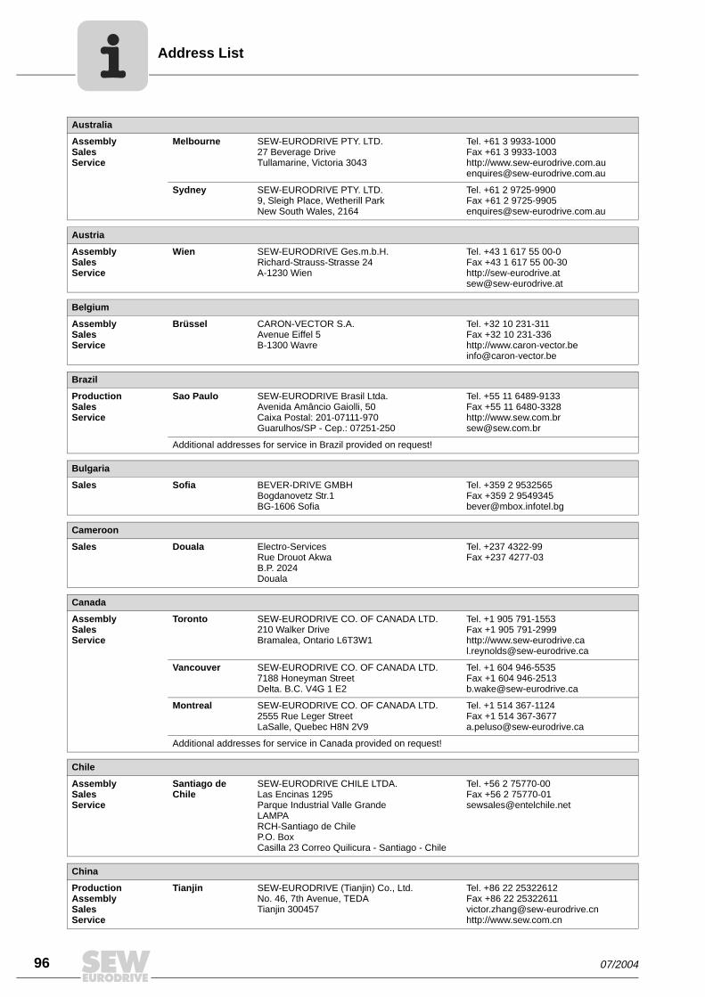
Address List
96 07/2004
Australia
AssemblySalesService
Melbourne SEW-EURODRIVE PTY. LTD.27 Beverage DriveTullamarine, Victoria 3043
Tel. +61 3 9933-1000Fax +61 3 9933-1003http://[email protected]
Sydney SEW-EURODRIVE PTY. LTD.9, Sleigh Place, Wetherill Park New South Wales, 2164
Tel. +61 2 9725-9900Fax +61 2 [email protected]
Austria
AssemblySalesService
Wien SEW-EURODRIVE Ges.m.b.H. Richard-Strauss-Strasse 24A-1230 Wien
Tel. +43 1 617 55 00-0Fax +43 1 617 55 00-30http://[email protected]
Belgium
AssemblySalesService
Brüssel CARON-VECTOR S.A.Avenue Eiffel 5B-1300 Wavre
Tel. +32 10 231-311Fax +32 10 231-336http://[email protected]
Brazil
ProductionSalesService
Sao Paulo SEW-EURODRIVE Brasil Ltda.Avenida Amâncio Gaiolli, 50Caixa Postal: 201-07111-970Guarulhos/SP - Cep.: 07251-250
Tel. +55 11 6489-9133Fax +55 11 6480-3328http://[email protected]
Additional addresses for service in Brazil provided on request!
Bulgaria
Sales Sofia BEVER-DRIVE GMBHBogdanovetz Str.1BG-1606 Sofia
Tel. +359 2 9532565Fax +359 2 [email protected]
Cameroon
Sales Douala Electro-ServicesRue Drouot AkwaB.P. 2024Douala
Tel. +237 4322-99Fax +237 4277-03
Canada
AssemblySalesService
Toronto SEW-EURODRIVE CO. OF CANADA LTD. 210 Walker Drive Bramalea, Ontario L6T3W1
Tel. +1 905 791-1553Fax +1 905 791-2999http://[email protected]
Vancouver SEW-EURODRIVE CO. OF CANADA LTD.7188 Honeyman Street Delta. B.C. V4G 1 E2
Tel. +1 604 946-5535Fax +1 604 [email protected]
Montreal SEW-EURODRIVE CO. OF CANADA LTD.2555 Rue Leger Street LaSalle, Quebec H8N 2V9
Tel. +1 514 367-1124Fax +1 514 [email protected]
Additional addresses for service in Canada provided on request!
Chile
AssemblySalesService
Santiago de Chile
SEW-EURODRIVE CHILE LTDA.Las Encinas 1295Parque Industrial Valle GrandeLAMPARCH-Santiago de ChileP.O. BoxCasilla 23 Correo Quilicura - Santiago - Chile
Tel. +56 2 75770-00Fax +56 2 [email protected]
China
ProductionAssemblySalesService
Tianjin SEW-EURODRIVE (Tianjin) Co., Ltd.No. 46, 7th Avenue, TEDA Tianjin 300457
Tel. +86 22 25322612Fax +86 22 [email protected]://www.sew.com.cn

Address List
07/2004 97
AssemblySalesService
Suzhou SEW-EURODRIVE (Suzhou) Co., Ltd.333, Suhong Middle RoadSuzhou Industrial ParkJiangsu Province, 215021P. R. China
Tel. +86 512 62581781Fax +86 512 [email protected]
Colombia
AssemblySalesService
Bogotá SEW-EURODRIVE COLOMBIA LTDA. Calle 22 No. 132-60Bodega 6, Manzana BSantafé de Bogotá
Tel. +57 1 54750-50Fax +57 1 [email protected]
Croatia
SalesService
Zagreb KOMPEKS d. o. o.PIT Erdödy 4 IIHR 10 000 Zagreb
Tel. +385 1 4613-158Fax +385 1 [email protected]
Czech Republic
Sales Praha SEW-EURODRIVE CZ S.R.O.Business Centrum Praha Luná 591CZ-16000 Praha 6 - Vokovice
Tel. +420 220121234 + 220121236Fax +420 220121237http://[email protected]
Denmark
AssemblySalesService
Kopenhagen SEW-EURODRIVEA/SGeminivej 28-30, P.O. Box 100DK-2670 Greve
Tel. +45 43 9585-00Fax +45 43 9585-09http://[email protected]
Estonia
Sales Tallin ALAS-KUUL ASPaldiski mnt.125EE 0006 Tallin
Tel. +372 6593230Fax +372 [email protected]
Finland
AssemblySalesService
Lahti SEW-EURODRIVE OYVesimäentie 4FIN-15860 Hollola 2
Tel. +358 3 589-300Fax +358 3 7806-211http://[email protected]
Gabon
Sales Libreville Electro-ServicesB.P. 1889Libreville
Tel. +241 7340-11Fax +241 7340-12
Great Britain
AssemblySalesService
Normanton SEW-EURODRIVE Ltd.Beckbridge Industrial Estate P.O. Box No.1GB-Normanton, West- Yorkshire WF6 1QR
Tel. +44 1924 893-855Fax +44 1924 893-702http://[email protected]
Greece
SalesService
Athen Christ. Boznos & Son S.A.12, Mavromichali StreetP.O. Box 80136, GR-18545 Piraeus
Tel. +30 2 1042 251-34 Fax +30 2 1042 251-59http://[email protected]
Hong Kong
AssemblySalesService
Hong Kong SEW-EURODRIVE LTD.Unit No. 801-806, 8th FloorHong Leong Industrial ComplexNo. 4, Wang Kwong Road Kowloon, Hong Kong
Tel. +852 2 7960477 + 79604654Fax +852 2 [email protected]
China

Address List
98 07/2004
Hungary
SalesService
Budapest SEW-EURODRIVE Kft.H-1037 BudapestKunigunda u. 18
Tel. +36 1 437 06-58Fax +36 1 437 [email protected]
India
AssemblySalesService
Baroda SEW-EURODRIVE India Pvt. Ltd.Plot No. 4, GidcPor Ramangamdi · Baroda - 391 243Gujarat
Tel. +91 265 2831021Fax +91 265 [email protected]
Technical Offices Bangalore SEW-EURODRIVE India Private Limited308, Prestige Centre Point7, Edward RoadBangalore
Tel. +91 80 22266565Fax +91 80 [email protected]
Mumbai SEW-EURODRIVE India Private Limited312 A, 3rd Floor, Acme PlazaAndheri Kurla Road, Andheri (E)Mumbai
Tel. +91 22 28348440Fax +91 22 [email protected]
Ireland
SalesService
Dublin Alperton Engineering Ltd. 48 Moyle RoadDublin Industrial EstateGlasnevin, Dublin 11
Tel. +353 1 830-6277Fax +353 1 830-6458
Italy
AssemblySalesService
Milano SEW-EURODRIVE di R. Blickle & Co.s.a.s.Via Bernini,14 I-20020 Solaro (Milano)
Tel. +39 2 96 9801Fax +39 2 96 [email protected]
Ivory Coast
Sales Abidjan SICASte industrielle et commerciale pour l’Afrique165, Bld de MarseilleB.P. 2323, Abidjan 08
Tel. +225 2579-44Fax +225 2584-36
Japan
AssemblySalesService
Toyoda-cho SEW-EURODRIVE JAPAN CO., LTD 250-1, Shimoman-no,Toyoda-cho, Iwata gunShizuoka prefecture, 438-0818
Tel. +81 538 373811Fax +81 538 [email protected]
Korea
AssemblySalesService
Ansan-City SEW-EURODRIVE KOREA CO., LTD. B 601-4, Banweol Industrial Estate Unit 1048-4, Shingil-DongAnsan 425-120
Tel. +82 31 492-8051Fax +82 31 [email protected]
Lebanon
Sales Beirut Gabriel Acar & Fils sarlB. P. 80484Bourj Hammoud, Beirut
Tel. +961 1 4947-86 +961 1 4982-72+961 3 2745-39Fax +961 1 4949-71 [email protected]
Lithuania
Sales Alytus UAB IrsevaMerkines g. 2ALT-4580 Alytus
Tel. +370 315 79204Fax +370 315 [email protected]
Luxembourg
AssemblySalesService
Brüssel CARON-VECTOR S.A.Avenue Eiffel 5B-1300 Wavre
Tel. +32 10 231-311Fax +32 10 231-336http://[email protected]

Address List
07/2004 99
Malaysia
AssemblySalesService
Johore SEW-EURODRIVE SDN BHD No. 95, Jalan Seroja 39, Taman Johor Jaya81000 Johor Bahru, JohorWest Malaysia
Tel. +60 7 3549409Fax +60 7 [email protected]
Morocco
Sales Casablanca S. R. M.Société de Réalisations Mécaniques 5, rue Emir Abdelkader05 Casablanca
Tel. +212 2 6186-69 + 6186-70 + 6186-71Fax +212 2 [email protected]
Netherlands
AssemblySalesService
Rotterdam VECTOR Aandrijftechniek B.V. Industrieweg 175 NL-3044 AS RotterdamPostbus 10085NL-3004 AB Rotterdam
Tel. +31 10 4463-700Fax +31 10 4155-552http://[email protected]
New Zealand
AssemblySalesService
Auckland SEW-EURODRIVE NEW ZEALAND LTD. P.O. Box 58-428 82 Greenmount driveEast Tamaki Auckland
Tel. +64 9 2745627Fax +64 9 [email protected]
Christchurch SEW-EURODRIVE NEW ZEALAND LTD. 10 Settlers Crescent, FerrymeadChristchurch
Tel. +64 3 384-6251Fax +64 3 [email protected]
Norway
AssemblySalesService
Moss SEW-EURODRIVE A/SSolgaard skog 71N-1599 Moss
Tel. +47 69 241-020Fax +47 69 [email protected]
Peru
AssemblySalesService
Lima SEW DEL PERU MOTORES REDUCTORES S.A.C.Los Calderos <FmSdata>[Idot ] 120-124Urbanizacion Industrial Vulcano, ATE, Lima
Tel. +51 1 3495280Fax +51 1 [email protected]
Poland
AssemblySalesService
Lodz SEW-EURODRIVE Polska Sp.z.o.o.ul. Techniczna 5 PL-92-518 Lodz
Tel. +48 42 67710-90Fax +48 42 67710-99http://[email protected]
Portugal
AssemblySalesService
Coimbra SEW-EURODRIVE, LDA. Apartado 15 P-3050-901 Mealhada
Tel. +351 231 20 9670Fax +351 231 20 3685http://[email protected]
Romania
SalesService
Bucuresti Sialco Trading SRL str. Madrid nr.4 011785 Bucuresti
Tel. +40 21 230-1328Fax +40 21 230-7170 [email protected]
Russia
Sales St. Petersburg ZAO SEW-EURODRIVE P.O. Box 263 RUS-195220 St. Petersburg
Tel. +7 812 5357142 +812 5350430Fax +7 812 5352287http://[email protected]

Address List
100 07/2004
Senegal
Sales Dakar SENEMECA Mécanique GénéraleKm 8, Route de Rufisque B.P. 3251, Dakar
Tel. +221 849 47-70Fax +221 849 [email protected]
Serbia and Montenegro
Sales Beograd DIPAR d.o.o.Kajmakcalanska 54SCG-11000 Beograd
Tel. +381 11 3046677Fax +381 11 [email protected]
Singapore
AssemblySalesService
Singapore SEW-EURODRIVE PTE. LTD. No 9, Tuas Drive 2 Jurong Industrial Estate Singapore 638644
Tel. +65 68621701 ... 1705Fax +65 68612827Telex 38 659 [email protected]
Slovakia
Sales Sered SEW-Eurodrive SK s.r.o.Trnavska 920SK-926 01 Sered
Tel. +421 31 7891311Fax +421 31 [email protected]
Slovenia
SalesService
Celje Pakman - Pogonska Tehnika d.o.o.UI. XIV. divizije 14SLO – 3000 Celje
Tel. +386 3 490 83-20Fax +386 3 490 [email protected]
South Africa
AssemblySalesService
Johannesburg SEW-EURODRIVE (PROPRIETARY) LIMITEDEurodrive House Cnr. Adcock Ingram and Aerodrome RoadsAeroton Ext. 2Johannesburg 2013P.O.Box 90004Bertsham 2013
Tel. +27 11 248-7000Fax +27 11 [email protected]
Capetown SEW-EURODRIVE (PROPRIETARY) LIMITED Rainbow ParkCnr. Racecourse & Omuramba RoadMontague GardensCape TownP.O.Box 36556Chempet 7442 Cape Town
Tel. +27 21 552-9820Fax +27 21 552-9830Telex 576 [email protected]
Durban SEW-EURODRIVE (PROPRIETARY) LIMITED2 Monaceo PlacePinetownDurbanP.O. Box 10433, Ashwood 3605
Tel. +27 31 700-3451Fax +27 31 [email protected]
Spain
AssemblySalesService
Bilbao SEW-EURODRIVE ESPAÑA, S.L. Parque Tecnológico, Edificio, 302E-48170 Zamudio (Vizcaya)
Tel. +34 9 4431 84-70Fax +34 9 4431 [email protected]
Sweden
AssemblySalesService
Jönköping SEW-EURODRIVE ABGnejsvägen 6-8S-55303 JönköpingBox 3100 S-55003 Jönköping
Tel. +46 36 3442-00Fax +46 36 3442-80http://[email protected]
Switzerland
AssemblySalesService
Basel Alfred lmhof A.G.Jurastrasse 10 CH-4142 Münchenstein bei Basel
Tel. +41 61 41717-17Fax +41 61 41717-00http://[email protected]

Address List
07/2004 101
Thailand
AssemblySalesService
Chon Buri SEW-EURODRIVE (Thailand) Ltd.Bangpakong Industrial Park 2700/456, Moo.7, Tambol DonhuarohMuang DistrictChon Buri 20000
Tel. +66 38 454281Fax +66 38 [email protected]
Tunisia
Sales Tunis T. M.S. Technic Marketing Service7, rue Ibn EI Heithem Z.I. SMMT2014 Mégrine Erriadh
Tel. +216 1 4340-64 + 1 4320-29Fax +216 1 4329-76
Turkey
AssemblySalesService
Istanbul SEW-EURODRIVE Hareket Sistemleri Sirketi Bagdat Cad. Koruma Cikmazi No. 3 TR-34846 Maltepe ISTANBUL
Tel. +90 216 4419163 + 216 4419164 + 216 3838014Fax +90 216 [email protected]
USA
ProductionAssemblySalesService
Greenville SEW-EURODRIVE INC. 1295 Old Spartanburg Highway P.O. Box 518Lyman, S.C. 29365
Tel. +1 864 439-7537Fax Sales +1 864 439-7830Fax Manuf. +1 864 439-9948Fax Ass. +1 864 439-0566Telex 805 550 http://[email protected]
AssemblySalesService
San Francisco SEW-EURODRIVE INC. 30599 San Antonio St.Hayward, California 94544-7101
Tel. +1 510 487-3560Fax +1 510 [email protected]
Philadelphia/PA SEW-EURODRIVE INC. Pureland Ind. Complex 2107 High Hill Road, P.O. Box 481Bridgeport, New Jersey 08014
Tel. +1 856 467-2277Fax +1 856 [email protected]
Dayton SEW-EURODRIVE INC.2001 West Main Street Troy, Ohio 45373
Tel. +1 937 335-0036Fax +1 937 [email protected]
Dallas SEW-EURODRIVE INC.3950 Platinum Way Dallas, Texas 75237
Tel. +1 214 330-4824Fax +1 214 [email protected]
Additional addresses for service in the USA provided on request!
Venezuela
AssemblySalesService
Valencia SEW-EURODRIVE Venezuela S.A.Av. Norte Sur No. 3, Galpon 84-319Zona Industrial Municipal NorteValencia, Estado Carabobo
Tel. +58 241 832-9804Fax +58 241 [email protected]@cantv.net


How we’re driving the world
With people who
think fast and
develop the
future with you.
With a worldwide
service network that is
always close at hand.
With drives and controls
that automatically
improve your productivity.
With comprehensive
knowledge in virtually
every branch of
industry today.
With uncompromising
quality that reduces the
cost and complexity of
daily operations.
With a global presence
that offers responsive
and reliable solutions.
Anywhere.
With innovative
technology that solves
tomorrow’s problems
today.
With online information
and software updates, via
the Internet, available
around the clock.
Gearmotors \ Industrial Gear Units \ Drive Electronics \ Drive Automation \ Services
SEW-EURODRIVEDriving the world
SEW-EURODRIVE GmbH & Co KG
P.O. Box 3023 · D-76642 Bruchsal / Germany
Phone +49 7251 75-0 · Fax +49 7251 75-1970
� www.sew-eurodrive.com