INDUSTRIAL CUTTING AND GOUGING EQUIPMENT -...
32
esab.com INDUSTRIAL CUTTING AND GOUGING EQUIPMENT
Transcript of INDUSTRIAL CUTTING AND GOUGING EQUIPMENT -...

esab.com
INDUSTRIAL CUTTING AND GOUGING EQUIPMENT

This information is accurate to the best of our knowledge at the time of printing and is subject to change at any time at ESAB’s sole discretion.
MANUAL GOUGING TORCH & CABLE ASSEMBLIES Gouging Torches (600 - 1000 Amp) . . . . . . . . . . . . . . . . . . . . . . . . . . . . . . . . . . . . . . . . . . . . . . . . 4 K3000™ . . . . . . . . . . . . . . . . . . . . . . . . . . . . . . . . . . . . . . . . . . . . . . . . . . . . . . . . . . . . . . . . . . . 6 - 7 K4000® . . . . . . . . . . . . . . . . . . . . . . . . . . . . . . . . . . . . . . . . . . . . . . . . . . . . . . . . . . . . . . . . . . . 6 - 7
Tri-Arc® Foundry Gouging Torches (1600 - 2200 Amp) . . . . . . . . . . . . . . . . . . . . . . . . . . . . . . 8 - 9 Straight Handle K-5 Manual Gouging Torch & Cable Assembly (1250 Amp) . . . . . . . . . . . . . . . . 10 Angle-Arc CSK4000 CutSkill® Manual Gouging Torch & Cable Assemblies (1000 Amp) . . . . . . . 10
ELECTRODES
Inches of Groove Per Electrode (Pointed CopperClad® & Jointed Jetrods) . . . . . . . . . . . . . . . . . 11Professional Air Carbon-Arc (Pointed, Flat, Half Round, Jointed) . . . . . . . . . . . . . . . . . . . . . . . . 12 CutSkill Electrodes (Pointed, Hollow, Jointed) . . . . . . . . . . . . . . . . . . . . . . . . . . . . . . . . . . . . . . . 13
WELDING CARBON PRODUCTS . . . . . . . . . . . . . . . . . . . . . . . . . . . . . . . . . . . . . . . . . 13
ARCAIR-MATIC® AUTOMATIC GOUGING SYSTEMS & ACCESSORIES N7500 Automated Gouging System & Cable Assemblies . . . . . . . . . . . . . . . . . . . . . . . . . . . . . . 14 Arcair-Matic Automatic BUG-O Travel System Packages . . . . . . . . . . . . . . . . . . . . . . . . . . . . . . 15 Arcair-Matic Automatic GULLCO Travel System Packages . . . . . . . . . . . . . . . . . . . . . . . . . . . . . 15 Arcair-Matic Automatic Titan Travel System Packages . . . . . . . . . . . . . . . . . . . . . . . . . . . . . . . . 16 Travel System Accessories . . . . . . . . . . . . . . . . . . . . . . . . . . . . . . . . . . . . . . . . . . . . . . . . . . . . . 17
SLICE® EXOTHERMIC TORCH, PACKAGES & CUTTING RODS Exothermic Cutting Torch . . . . . . . . . . . . . . . . . . . . . . . . . . . . . . . . . . . . . . . . . . . . . . . . . . 18 - 19 Utility Pack . . . . . . . . . . . . . . . . . . . . . . . . . . . . . . . . . . . . . . . . . . . . . . . . . . . . . . . . . . . . . . . . . 20 Battery Pack . . . . . . . . . . . . . . . . . . . . . . . . . . . . . . . . . . . . . . . . . . . . . . . . . . . . . . . . . . . . . . . . . 20 SLICE Exothermic Cutting Rods . . . . . . . . . . . . . . . . . . . . . . . . . . . . . . . . . . . . . . . . . . . . . . . . . 20 SLICE Indistrial Pack . . . . . . . . . . . . . . . . . . . . . . . . . . . . . . . . . . . . . . . . . . . . . . . . . . . . . . . . . . 21 SLICE Complete Pack . . . . . . . . . . . . . . . . . . . . . . . . . . . . . . . . . . . . . . . . . . . . . . . . . . . . . . . . . 21
UNDERWATER CUTTING & WELDING TORCHES & CONSUMABLES Sea Torch “Combination Torch” . . . . . . . . . . . . . . . . . . . . . . . . . . . . . . . . . . . . . . . . . . . . . . . . . 22 Underwater Cutting Electrodes . . . . . . . . . . . . . . . . . . . . . . . . . . . . . . . . . . . . . . . . . . . . . . . . . . 22 Sea Stinger® II Torch . . . . . . . . . . . . . . . . . . . . . . . . . . . . . . . . . . . . . . . . . . . . . . . . . . . . . . . . . . . 23 Underwater Welding & Gouging Electrodes . . . . . . . . . . . . . . . . . . . . . . . . . . . . . . . . . . . . . . . . . 23 Arcwater® II Torch . . . . . . . . . . . . . . . . . . . . . . . . . . . . . . . . . . . . . . . . . . . . . . . . . . . . . . . . . . . . . 23
PROTEX ANTI-SPLATTER CHEMICALS . . . . . . . . . . . . . . . . . . . . . . . . . . . . . . 24 - 27
WARRANTY . . . . . . . . . . . . . . . . . . . . . . . . . . . . . . . . . . . . . . . . . . . . . . . . . . . . . . . . . . . . . . . 28
TABLE OF CONTENTS
1Int’l Customer Care: 1-940-381-1212 / fax 1-940-483-8178
esab.com
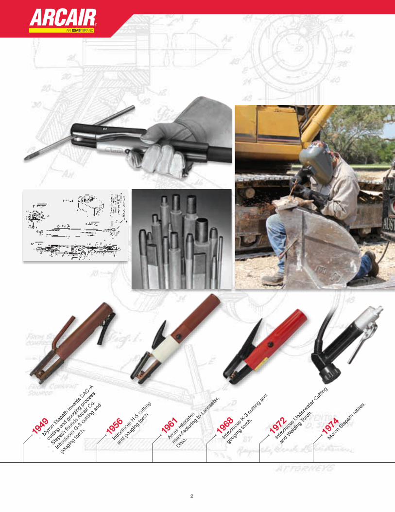
1949
• M
yron
Stepat
h inv
ents
CAC-A
cutti
ng an
d gou
ging
proce
ss .
• Ste
path
foun
ds Arc
air C
o .
• Int
roduc
es G
-3 cu
tting
and
goug
ing to
rch . 19
56
Intro
duces
H-5
cutti
ng
and g
ougin
g to
rch .
1961
Arcair
reloc
ates
man
ufac
turin
g to
Lan
caste
r,
Ohio .
1968
Intro
duces
K-3
cutti
ng an
d
goug
ing to
rch .
1972
Intro
duces
Und
erwat
er C
uttin
g
and W
elding
Torc
h .
1974
Myro
n Ste
path
retir
es .
2
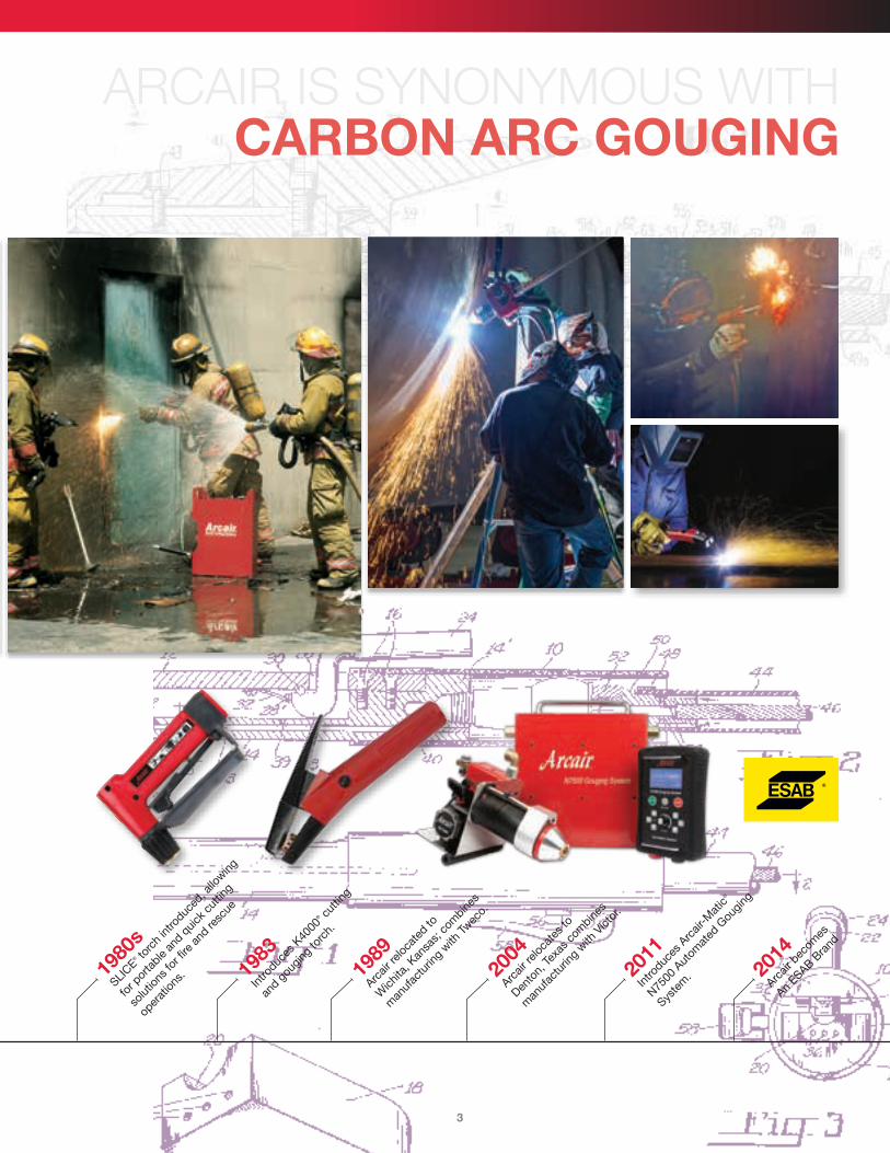
1980
s
SLICE® to
rch
intro
duced
, allo
wing
for p
orta
ble an
d quic
k cut
ting
solut
ions f
or fir
e and
resc
ue
oper
ation
s . 1983
Intro
duces
K40
00® cu
tting
and g
ougin
g to
rch .
1989
Arcair
reloc
ated
to
Wich
ita, K
ansa
s; co
mbine
s
man
ufac
turin
g with
Twec
o .
2004
Arcair
reloc
ates
to
Dento
n, Te
xas c
ombine
s
man
ufac
turin
g with
Vict
or .
2011
Intro
duces
Arc
air-M
atic
®
N7500
Aut
omat
ed G
ougin
g
Syste
m .
ARCAIR IS SYNONYMOUS WITH CARBON ARC GOUGING
2014
Arcair
bec
omes
An ESAB B
rand
3

MA
NU
AL
GO
UG
ING
GOUGING TORCHESFEATURES & BENEFITS
IMPROVED TORCH AIR FLOW�n More efficient use of air supply . Improved metal removal .
FOUR HOLE HEAD ASSEMBLY�n Optimizes air flow to the arc . Efficiently cleans slag from
groove edge .
AIR ASSIST POSITIVE AIR SHUT-OFFn Minimizes air supply unit cycling on and off . Allows torch usage
when air supply is marginal .
IMPROVED CABLE ELECTRICAL CONDUCTION�n Improves cable service life . Decreases heat build up in cable
and torch .
SUPERIOR OUTER CABLE COVER�n Durable cover for improved cable life in a harsh environment . Resists
breakdown due to exposure to heat produced by gouging .
INSULATED CONNECTION BOOT & HOOK-UP KIT�n Makes for easy torch hook-up . Virtually eliminates the possibility
of arcing when contacting electrically hot parts .
Straight HandleGouging Torches
Angle-Arc®
Gouging Torches
Tri-Arc®
Gouging Torches
THE NEW CARBON-ARC TORCH CABLE “BOOT” DESIGNFEATURES & BENEFITS n Patented two-piece boot design
Molded from a hard nylon reinforced fiber polymer made to withstand the substantial abuse in shop and field applications
n Helps prevent accidental arcing No chance of the “boot” pulling away from the power connection as seen with prior “boot” design
n Ease of replacement in the field Threaded screws holds the two halves together and can be loosened with a standard straight blade screwdriver
n Available in two (2) different molded “boot” housing configurations
Conventional Boot (Part No. 94-105-032) – Accepts one 4/0 welding cable from the power supply and one 3/4"
diameter air hose assembly providing current and compressed air
Quick-Connect Hook-Up Kit (Part No. 94-463-046) – Twist lock-style power connection and air hose extending from the
rear of the torch cable . This option allows the operator to connect or disconnect the incoming power lead and air line quickly and easily
NOTE: Replacement Boots will fit onto all Arcair® manual hand torch cable assemblies having an amperage range of 1000 Amps or less .
Quick-Connect Hook-Up Kit Replacement Part No . 94-463-046
Conventional Replacement Part No . 94-105-032
Patent No . D708,240 S
Help prevent accidental arcing in your workplace
THE “BEST” JUST GOT BETTER
4U.S. Customer Care: 1-800-426-1888 / fax 1-800-535-0557 Canada Customer Care: 1-905-827-4515 / fax 1-800-588-1714
MA
NU
AL
GO
UG
ING
GOUGING TORCH SELECTION GUIDE
Copperclad ElectrodesAmperage Range
Recommended Alternate90 – 450 450 - 1000 1000 -1400
1400 – 2000
2000 - 2400
1/8" - 3/8" Round (3 .2 mm - 9 .5 mm) 3/8" & 5/8" Flats (9 .5 mm & 15 .9 mm) K3000™
5/32" – 1/2" Round (4 .0 mm – 12 .7 mm) 3/8" & 5/8" Flats (9 .5 mm & 15 .9 mm) K4000® K3000™
5/16" - 5/8" Round (7 .9 mm - 15 .9 mm) K-5 K4000®, Tri-Arc®
5/16" – 1" Round (7 .9 mm – 25 .4 mm) Tri-Arc®
WHICH TORCH IS RIGHT FOR YOU?
Torch Model
Amperage (Maximum)
Swivel Cable
Swivel Cable
Lengths (Ft)
Air-Cooled Water-Cooled
Handle Design
Body/Upper Arm
ConstructionApplication Special Features
K3000™ 600 360˚ 7 ft & 10 ft Air-Cooled Small & Ergonomic Brass
Medium Duty
All brass torch parts with a copper head assembly having 4-hole design
K4000® 1000 360˚ 7 ft & 10 ft Air-Cooled Small & Ergonomic Brass Heavy Duty All brass torch parts with a copper head
assembly having 4-hole design
K-5 1250 340˚ 7 ft & 10 ft Air-Cooled Straight Brass Heavy Duty All brass torch parts with a copper head assembly having 4-hole design
Tri-Arc® 2200 340˚ 7 ft & 10 ftAir-Cooled & Water-Cooled
Straight Copper Heavy DutyVersatility with three (3) different head assemblies to choose from to meet any metal removal application
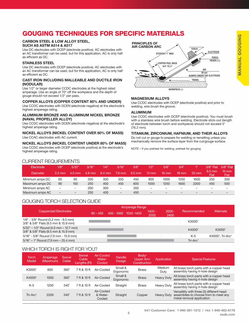
GOUGING TECHNIQUES FOR SPECIFIC MATERIALSCARBON STEEL & LOW ALLOY STEEL, SUCH AS ASTM A514 & A517Use DC electrodes with DCEP (electrode positive) . AC electrodes with an AC transformer can be used, but for this application, AC is only half as efficient as DC .
STAINLESS STEELUse DC electrodes with DCEP (electrode positive) . AC electrodes with an AC transformer can be used, but for this application, AC is only half as efficient as DC .
CAST IRON INCLUDING MALLEABLE AND DUCTILE IRON (NODULAR)Use 1/2" or larger diameter CCDC electrodes at the highest rated amperage . Use an angle of 70° off the workpiece and the depth of gouge should not exceed 1/2" per pass .
COPPER ALLOYS (COPPER CONTENT 60% AND UNDER)Use CCDC electrodes with DCEN (electrode negative) at the electrode’s highest amperage rating .
ALUMINUM BRONZE AND ALUMINUM NICKEL BRONZE (NAVAL PROPELLER ALLOY)Use CCDC electrodes with DCEN (electrode negative) at the electrode’s highest amperage rating .
NICKEL ALLOYS (NICKEL CONTENT OVER 80% OF MASS)Use CCAC electrodes with AC current .
NICKEL ALLOYS (NICKEL CONTENT UNDER 80% OF MASS)Use CCDC electrodes with DCEP (electrode positive) at the electrode’s highest amperage rating .
MAGNESIUM ALLOYSUse CCDC electrodes with DCEP (electrode positive) and prior to welding, wire brush the groove .
ALUMINUMUse CCDC electrodes with DCEP (electrode positive) . You must brush with a stainless wire brush before welding . Electrode stick-out (length of electrode between torch and workpiece) should not exceed 3" (76 .2 mm) .
TITANIUM, ZIRCONIUM, HAFNIUM, AND THEIR ALLOYSDo not cut or gouge to prepare for welding or remelting unless you mechanically remove the surface layer from the cut/gouge surface .
NOTE – If you preheat for welding, preheat for gouging
TRAVEL
PRINCIPLES OFAIR CARBON ARC
WORKPIECE (-)
AIR80 psi
ALWAYS UNDER THE ELECTRODE
COPPER PEEL BACK3/4" TO 2"
STICKOUT 7" MAX
TORCHELECTRODE
TORCHHEADS (+)
CURRENT REQUIREMENTS Electrode 1/8" 5/32" 3/16" 1/4" 5/16" 3/8" 1/2" 5/8" 3/4" 1" 3/8" Flat 5/8" Flat
Diameter 3 .2 mm 4 .0 mm 4 .8 mm 6 .4 mm 7 .9 mm 9 .5 mm 13 mm 16 mm 19 mm 25 mm 9 .5 mm Flat
16 mm Flat
Minimum amps DC 60 90 200 300 350 450 800 1000 1250 1600 250 300Maximum amps DC 90 150 250 400 450 600 1000 1250 1600 2200 450 500Minimum amps AC – – 200 300 – 350 – – – – – –Maximum amps AC – – 250 400 – 450 – – – – – –
5Int’l Customer Care: 1-940-381-1212 / fax 1-940-483-8178
esab.com
MA
NU
AL
GO
UG
ING
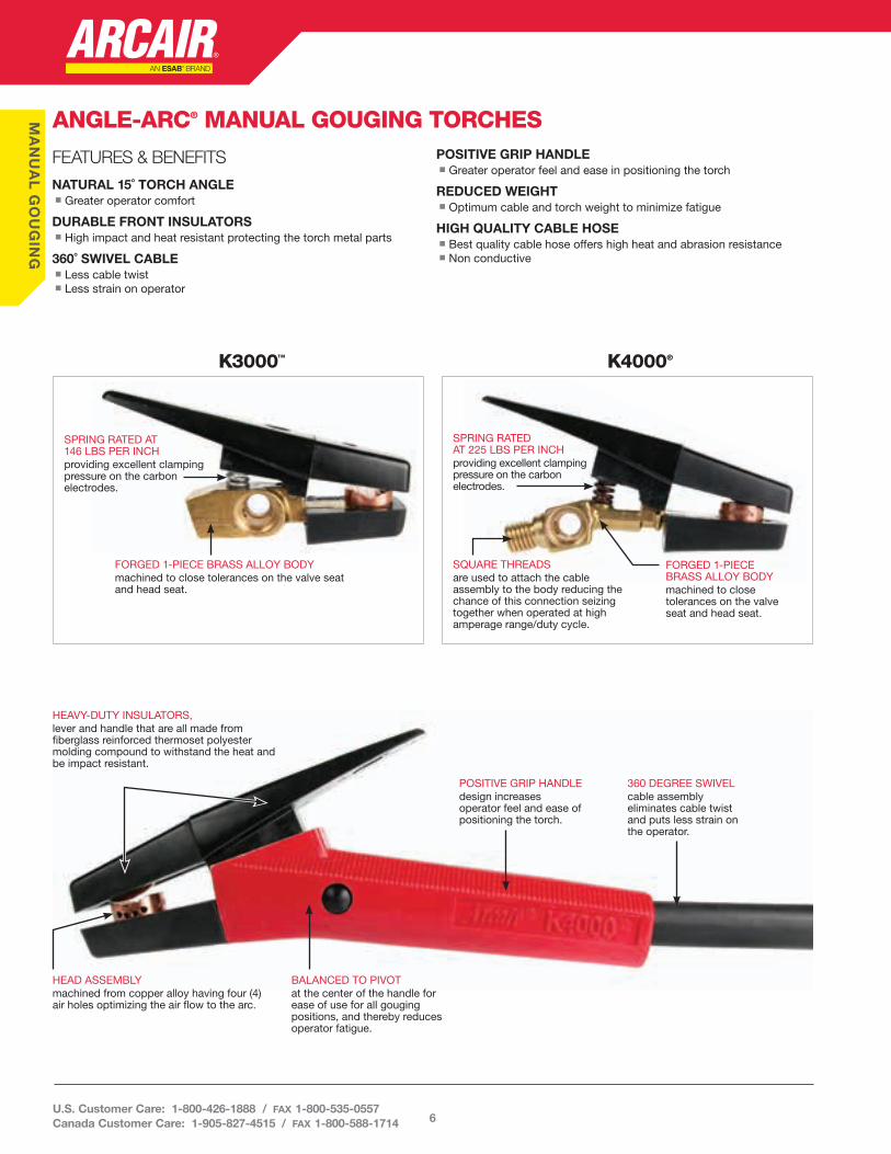
HEAVY-DUTY INSULATORS, lever and handle that are all made from fiberglass reinforced thermoset polyester molding compound to withstand the heat and be impact resistant .
ANGLE-ARC® MANUAL GOUGING TORCHES
HEAD ASSEMBLY machined from copper alloy having four (4) air holes optimizing the air flow to the arc .
POSITIVE GRIP HANDLE design increases operator feel and ease of positioning the torch .
BALANCED TO PIVOT at the center of the handle for ease of use for all gouging positions, and thereby reduces operator fatigue .
360 DEGREE SWIVEL cable assembly eliminates cable twist and puts less strain on the operator .
SPRING RATED AT 225 LBS PER INCH providing excellent clamping pressure on the carbon electrodes .
SPRING RATED AT 146 LBS PER INCHproviding excellent clamping pressure on the carbon electrodes .
SQUARE THREADS are used to attach the cable assembly to the body reducing the chance of this connection seizing together when operated at high amperage range/duty cycle .
FORGED 1-PIECE BRASS ALLOY BODY machined to close tolerances on the valve seat and head seat .
FORGED 1-PIECE BRASS ALLOY BODY machined to close tolerances on the valve seat and head seat .
K4000®K3000™
FEATURES & BENEFITS
NATURAL 15˚ TORCH ANGLEn Greater operator comfort
DURABLE FRONT INSULATORS n High impact and heat resistant protecting the torch metal parts
360˚ SWIVEL CABLEn Less cable twistn Less strain on operator
POSITIVE GRIP HANDLEn Greater operator feel and ease in positioning the torch
REDUCED WEIGHTn Optimum cable and torch weight to minimize fatigue
HIGH QUALITY CABLE HOSEn Best quality cable hose offers high heat and abrasion resistancen Non conductive
6U.S. Customer Care: 1-800-426-1888 / fax 1-800-535-0557 Canada Customer Care: 1-905-827-4515 / fax 1-800-588-1714

MA
NU
AL
GO
UG
INGK4000®
Heavy Duty - Heavy metal removal applications such as weld preparations in pressure vessel shops and shipyards
AMPERAGE RANGEn 90 – 1000 amps
ELECTRODE SIZEn Pointed - 5/32" - 1/2" round (4 .0 mm - 12 .7 mm)n Jointed - 5/16" - 1/2" round (7 .9 mm - 12 .7 mm)n Flat - 3/8" and 5/8" (9 .5 mm - 15 .9 mm)n Half Round - 5/8" (15 .9 mm)
AIR REQUIREMENTSn psi – 80n kg/cm² – 5 .6n cfm – 25n l/min – 708
Part No . Description01-082-002 Torch Only61-082-008 Torch w/7 ft (2 .1 m) 360° Swivel Cable
61-082-006Torch w/7 ft (2 .1 m) 360° Swivel Cable & Insulated
Hook-Up Kit61-082-009 Torch w/10 ft (3 m) 360° Swivel Cable
61-082-007Torch w/10 ft (3 m) 360° Swivel Cable & Insulated
Hook-Up Kit
K3000™
Medium Duty - General repair and maintenance jobs such as mining, construction, and all types of metal fabrication
AMPERAGE RANGEn 90 – 600 amps
ELECTRODE SIZEn Pointed - 1/8" - 3/8" round (3 .2 mm - 9 .5 mm)n Jointed - 5/16" - 3/8" round (7 .9 mm - 9 .5 mm)n Flat - 3/8" and 5/8" (9 .5 mm - 15 .9 mm)n Half Round - 5/8" (15 .9 mm)
AIR REQUIREMENTSn psi – 80n kg/cm² – 5 .6n cfm – 22n l/min – 624
Part No . Description01-065-001 Torch Only61-065-006 Torch w/7 ft (2 .1 m) 360° Swivel Cable
61-065-002Torch w/7 ft (2 .1 m) 360° Swivel Cable & Insulated
Hook-Up Kit61-065-007 Torch w/10 ft (3 m) 360° Swivel Cable
61-065-003Torch w/10 ft (3 m) 360° Swivel Cable & Insulated
Hook-Up Kit
K3000 360° Swivel Cable
K4000 360° Swivel Cable
SWIVEL CABLE ASSEMBLY OPTIONS
Part No .Description
K3000 K4000
70-088-107 70-084-207 7 ft (2 .1 m) 360° Swivel Cable Assembly
70-088-110 70-084-210 10 ft (3 m) 360° Swivel Cable Assembly
7Int’l Customer Care: 1-940-381-1212 / fax 1-940-483-8178
esab.com
MA
NU
AL
GO
UG
ING
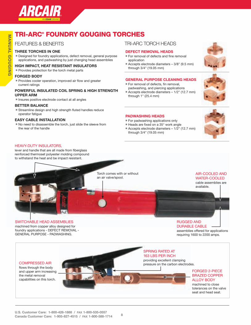
TRI-ARC® FOUNDRY GOUGING TORCHESFEATURES & BENEFITS
THREE TORCHES IN ONEn Designed for foundry applications, defect removal, general purpose
applications, and padwashing by just changing head assemblies
HIGH IMPACT, HEAT RESISTANT INSULATORSn Provides protection for the torch metal parts
FORGED BODYn Provides cooler operation, improved air flow and greater
current ratings
POWERFUL INSULATED COIL SPRING & HIGH STRENGTH UPPER ARMn Insures positive electrode contact at all angles
BETTER BALANCEn Streamline design and high strength fluted handles reduce
operator fatigue
EASY CABLE INSTALLATIONn No need to disassemble the torch, just slide the sleeve from
the rear of the handle
HEAVY-DUTY INSULATORS, lever and handle that are all made from fiberglass reinforced thermoset polyester molding compound to withstand the heat and be impact resistant .
SWITCHABLE HEAD ASSEMBLIES machined from copper alloy designed for foundry applications - DEFECT REMOVAL - GENERAL PURPOSE - PADWASHING .
RUGGED AND DURABLE CABLE assemblies offered for applications requiring 1600 to 2200 amps .
Torch comes with or without an air valve/spool .
AIR-COOLED AND WATER-COOLEDcable assemblies are available .
SPRING RATED AT 163 LBS PER INCHproviding excellent clamping pressure on the carbon electrodes .
FORGED 2-PIECE BRAZED COPPER ALLOY BODY machined to close tolerances on the valve seat and head seat .
COMPRESSED AIR flows through the body and upper arm increasing the metal removal capabilities on this torch .
TRI-ARC TORCH HEADS
DEFECT REMOVAL HEADSn For removal of defects and fine removal
applicationn Accepts electrode diameters – 3/8" (9 .5 mm)
through 3/4" (19 .05 mm)
GENERAL PURPOSE CLEANING HEADSn For removal of defects, fin removal,
padwashing, and piercing applicationsn Accepts electrode diameters – 1/2" (12 .7 mm)
through 1" (25 .4 mm)
PADWASHING HEADS n For padwashing applications onlyn Heads are fixed on a 35° work anglen Accepts electrode diameters – 1/2" (12 .7 mm)
through 3/4" (19 .05 mm)
8U.S. Customer Care: 1-800-426-1888 / fax 1-800-535-0557 Canada Customer Care: 1-905-827-4515 / fax 1-800-588-1714

MA
NU
AL
GO
UG
INGSWIVEL CABLE ASSEMBLY
OPTIONS
Part No .Description
7 ft (2 .1M) 10 ft (3M)
74-143-607 74-143-610Std . Duty - 340° Swivel Cable
Assembly74-161-907 – E-H-D 340° Swivel Cable Assembly
74-085-207 74-085-210Water-Cooled Cable Assembly - Non-
Swivel
TRI-ARC®
Foundry - General foundry work, pad washing, defect, nails, sprue and interior work
AMPERAGE RANGEn 450 – 2200 amps
ELECTRODE SIZEn 5/16" - 1" Round (7 .9 mm - 25 .4 mm)
AIR REQUIREMENTSn psi – 80n kg/cm² – 5 .6n cfm – 33n l/min – 934
Part No . Description Electrode Size
NO HEADS IN TORCH
02-991-411 Torch Only –
62-991-417 Torch & 7 ft (2 .1 m) Cable –
NO HEADS IN TORCH - NO VALVE
02-991-426 Torch Only –
DEFECT REMOVAL HEADS
94-378-298 Replacement Heads3/8" (9 .5 mm) thru 3/4"
(19 .05 mm)
PADWASHING HEADS
94-378-286 Replacement Heads 1/2" (12 .7 mm)
94-378-289 Replacement Heads 5/8" (15 .9 mm)
94-378-283 Replacement Heads 3/4" (19 .05 mm)
GENERAL PURPOSE CLEANING HEADS
94-378-267 Replacement Heads 1/2" (12 .7 mm)
94-378-270 Replacement Heads 5/8" (15 .9 mm)
94-378-273 Replacement Heads 3/4" (19 .05 mm)
94-378-343 Replacement Heads 1" (25 .4 mm)
Note: The cable assembly that comes standard on the assemblies is Part No . 74-143-607, 7 ft (2 .1 m) long and rated for 1600 amperes maximum .
Part No . Description
70-128-5077 ft (2 .1 m) 340° Swivel Cable
Assembly
70-128-51010 ft (3 m) 340° Swivel Cable
Assembly
K-5 Swivel Cable
9Int’l Customer Care: 1-940-381-1212 / fax 1-940-483-8178
esab.com

MA
NU
AL
GO
UG
ING
STRAIGHT HANDLE MANUAL GOUGING TORCHESFEATURES & BENEFITS
RELIABLE TORCH DESIGNn Market leader for over 60+ yearsn Greater operator comfort
ACCEPTS A WIDE RANGE OF CCDC GOUGING ELECTRODESn 5/16" (7 .9 mm) - through 5/8" (15 .9 mm) round
DURABLE FRONT INSULATORSn High impact and heat resistant protecting the torch metal parts
SWIVEL CABLEn Less cable twistn Less strain on the operator
HIGH QUALITY CABLE HOSE n Best quality cable hose offers high heat and abrasion resistancen Non-conductive
RUGGED CONSTRUCTION OVERALLn Can withstand harsh environments
K-5Extra Heavy Duty - Heavy metal removal applications such as weld preparations in pressure vessel shops, shipyards and defect removal in foundries
AMPERAGE RANGEn 450 - 1250 amps
ELECTRODE SIZEn Pointed - 5/16" - 1/2" round (7 .9 mm - 12 .7 mm)n Jointed - 5/16" - 5/8" round (7 .9 mm - 15 .9 mm)n Half Round - 5/8" (15 .9 mm)
AIR REQUIREMENTSn psi – 80n kg/cm² – 5 .6n cfm – 30n l/min – 850
Part No . Description01-104-003 Torch Only61-104-007 Torch w/7 ft (2 .1 m 360° Swivel Cable61-104-008 Torch w/10 ft (3 m) 360° Swivel Cable
CSK4000Heavy Duty - Heavy metal removal applications such as weld preparations in pressure vessel shops and shipyards
ELECTRODE SIZEn Pointed - 5/32" - 1/2" round (4 .0 mm - 12 .7 mm)n Jointed - 5/16" - 1/2" round (7 .9 mm - 12 .7 mm)n Flat - 3/8" and 5/8" (9 .5 mm - 15 .9 mm)n Half Round - 5/8" (15 .9 mm)
AIR REQUIREMENTSn Maximum Amperage – 1000 ampsn Compressed Air – 80 psi (5 .6 kg/cm²)n Compressed Air Flow Rate – 28 cfm (0 .79 m³/min)n Torch and Cable Weight: 5 .4 lbs (2 .4 kg)
Part No . Description01-088-000 Torch Only61-088-007 Torch & 7 ft (2 .1 m) Cable Assembly61-088-010 Torch & 10 ft (3 m) Cable Assembly70-088-007 7 ft (2 .1 m) Cable Assembly70-088-010 10 ft (3 m) Cable Assembly
FEATURES & BENEFITS
NATURAL 15˚ TORCH ANGLEn Greater operator comfort
DURABLE FRONT INSULATORS n High impact and heat resistant protecting the torch metal parts
360˚ SWIVEL CABLEn Less cable twistn Less strain on operator
POSITIVE GRIP HANDLEn Greater operator feel and ease in positioning the torch
REDUCED WEIGHTn Optimum cable and torch weight to minimize fatigue
HIGH QUALITY CABLE HOSEn Best quality cable hose offers high heat and abrasion resistancen Non conductive
CUTSKILL MANUAL GOUGING TORCHES
10U.S. Customer Care: 1-800-426-1888 / fax 1-800-535-0557 Canada Customer Care: 1-905-827-4515 / fax 1-800-588-1714
EL
EC
TR
OD
ES
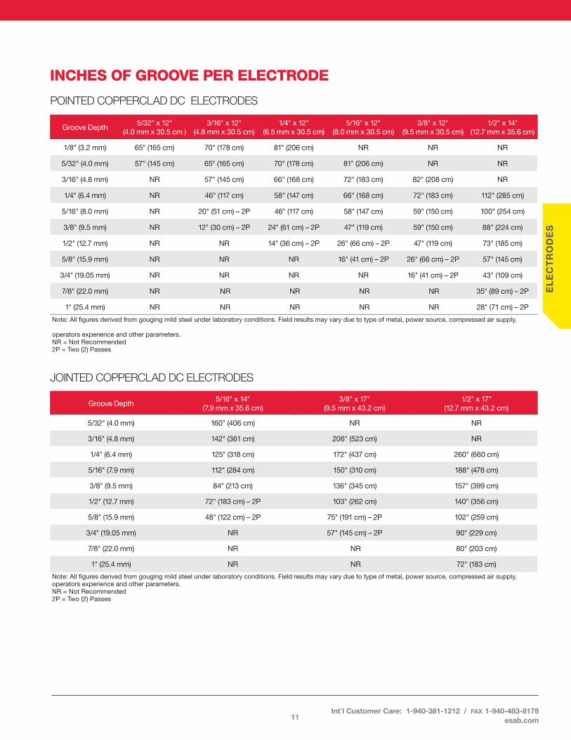
INCHES OF GROOVE PER ELECTRODE
POINTED COPPERCLAD DC ELECTRODES
Groove Depth 5/32" x 12"
(4 .0 mm x 30 .5 cm )3/16" x 12"
(4 .8 mm x 30 .5 cm)1/4" x 12"
(6 .5 mm x 30 .5 cm)5/16" x 12"
(8 .0 mm x 30 .5 cm)3/8" x 12"
(9 .5 mm x 30 .5 cm)1/2" x 14"
(12 .7 mm x 35 .6 cm)
1/8" (3 .2 mm) 65" (165 cm) 70" (178 cm) 81" (206 cm) NR NR NR
5/32" (4 .0 mm) 57" (145 cm) 65" (165 cm) 70" (178 cm) 81" (206 cm) NR NR
3/16" (4 .8 mm) NR 57" (145 cm) 66" (168 cm) 72" (183 cm) 82" (208 cm) NR
1/4" (6 .4 mm) NR 46" (117 cm) 58" (147 cm) 66" (168 cm) 72" (183 cm) 112" (285 cm)
5/16" (8 .0 mm) NR 20" (51 cm) – 2P 46" (117 cm) 58" (147 cm) 59" (150 cm) 100" (254 cm)
3/8" (9 .5 mm) NR 12" (30 cm) – 2P 24" (61 cm) – 2P 47" (119 cm) 59" (150 cm) 88" (224 cm)
1/2" (12 .7 mm) NR NR 14" (36 cm) – 2P 26" (66 cm) – 2P 47" (119 cm) 73" (185 cm)
5/8" (15 .9 mm) NR NR NR 16" (41 cm) – 2P 26" (66 cm) – 2P 57" (145 cm)
3/4" (19 .05 mm) NR NR NR NR 16" (41 cm) – 2P 43" (109 cm)
7/8" (22 .0 mm) NR NR NR NR NR 35" (89 cm) – 2P
1" (25 .4 mm) NR NR NR NR NR 28" (71 cm) – 2P
Note: All figures derived from gouging mild steel under laboratory conditions . Field results may vary due to type of metal, power source, compressed air supply,
operators experience and other parameters .NR = Not Recommended 2P = Two (2) Passes
JOINTED COPPERCLAD DC ELECTRODES
Groove Depth 5/16" x 14"
(7 .9 mm x 35 .6 cm)3/8" x 17"
(9 .5 mm x 43 .2 cm)1/2" x 17"
(12 .7 mm x 43 .2 cm)
5/32" (4 .0 mm) 160" (406 cm) NR NR
3/16" (4 .8 mm) 142" (361 cm) 206" (523 cm) NR
1/4" (6 .4 mm) 125" (318 cm) 172" (437 cm) 260" (660 cm)
5/16" (7 .9 mm) 112" (284 cm) 150" (310 cm) 188" (478 cm)
3/8" (9 .5 mm) 84" (213 cm) 136" (345 cm) 157" (399 cm)
1/2" (12 .7 mm) 72" (183 cm) – 2P 103" (262 cm) 140" (356 cm)
5/8" (15 .9 mm) 48" (122 cm) – 2P 75" (191 cm) – 2P 102" (259 cm)
3/4" (19 .05 mm) NR 57" (145 cm) – 2P 90" (229 cm)
7/8" (22 .0 mm) NR NR 80" (203 cm)
1" (25 .4 mm) NR NR 72" (183 cm)
Note: All figures derived from gouging mild steel under laboratory conditions . Field results may vary due to type of metal, power source, compressed air supply, operators experience and other parameters .NR = Not Recommended2P = Two (2) Passes
11Int’l Customer Care: 1-940-381-1212 / fax 1-940-483-8178
esab.com
EL
EC
TR
OD
ES
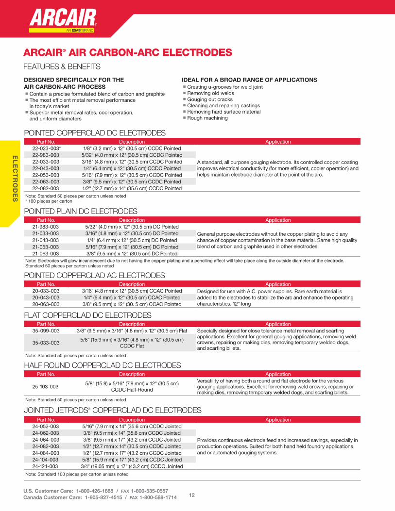
ARCAIR® AIR CARBON-ARC ELECTRODESFEATURES & BENEFITS
POINTED COPPERCLAD DC ELECTRODESPart No . Description Application
22-023-003* 1/8" (3 .2 mm) x 12" (30 .5 cm) CCDC Pointed
A standard, all purpose gouging electrode . Its controlled copper coating improves electrical conductivity (for more efficient, cooler operation) and helps maintain electrode diameter at the point of the arc .
22-983-003 5/32" (4 .0 mm) x 12" (30 .5 cm) CCDC Pointed 22-033-003 3/16" (4 .8 mm) x 12" (30 .5 cm) CCDC Pointed 22-043-003 1/4" (6 .4 mm) x 12" (30 .5 cm) CCDC Pointed 22-053-003 5/16" (7 .9 mm) x 12" (30 .5 cm) CCDC Pointed 22-063-003 3/8" (9 .5 mm) x 12" (30 .5 cm) CCDC Pointed 22-082-003 1/2" (12 .7 mm) x 14" (35 .6 cm) CCDC PointedNote: Standard 50 pieces per carton unless noted* 100 pieces per carton
POINTED PLAIN DC ELECTRODESPart No . Description Application
21-983-003 5/32" (4 .0 mm) x 12" (30 .5 cm) DC PointedGeneral purpose electrodes without the copper plating to avoid any chance of copper contamination in the base material . Same high quality blend of carbon and graphite used in other electrodes .
21-033-003 3/16" (4 .8 mm) x 12" (30 .5 cm) DC Pointed 21-043-003 1/4" (6 .4 mm) x 12" (30 .5 cm) DC Pointed 21-053-003 5/16" (7 .9 mm) x 12" (30 .5 cm) DC Pointed 21-063-003 3/8" (9 .5 mm) x 12" (30 .5 cm) DC PointedNote: Electrodes will glow incandescent due to not having the copper plating and a penciling affect will take place along the outside diameter of the electrode . Standard 50 pieces per carton unless noted
POINTED COPPERCLAD AC ELECTRODESPart No . Description Application
20-033-003 3/16" (4 .8 mm) x 12" (30 .5 cm) CCAC Pointed Designed for use with A .C . power supplies . Rare earth material is added to the electrodes to stabilize the arc and enhance the operating characteristics . 12" long
20-043-003 1/4" (6 .4 mm) x 12" (30 .5 cm) CCAC Pointed 20-063-003 3/8" (9 .5 mm) x 12" (30 . 5 cm) CCAC Pointed
FLAT COPPERCLAD DC ELECTRODESPart No . Description Application
35-099-003 3/8" (9 .5 mm) x 3/16" (4 .8 mm) x 12" (30 .5 cm) Flat Specially designed for close tolerance metal removal and scarfing applications . Excellent for general gouging applications, removing weld crowns, repairing or making dies, removing temporary welded dogs, and scarfing billets .
35-033-0035/8" (15 .9 mm) x 3/16" (4 .8 mm) x 12" (30 .5 cm)
CCDC Flat
Note: Standard 50 pieces per carton unless noted
HALF ROUND COPPERCLAD DC ELECTRODESPart No . Description Application
25-103-0035/8" (15 .9) x 5/16" (7 .9 mm) x 12" (30 .5 cm)
CCDC Half-Round
Versatility of having both a round and flat electrode for the various gouging applications . Excellent for removing weld crowns, repairing or making dies, removing temporary welded dogs, and scarfing billets .
Note: Standard 50 pieces per carton unless noted
JOINTED JETRODS® COPPERCLAD DC ELECTRODESPart No . Description Application
24-052-003 5/16" (7 .9 mm) x 14" (35 .6 cm) CCDC Jointed
Provides continuous electrode feed and increased savings, especially in production operations . Suited for both hand held foundry applications and or automated gouging systems .
24-062-003 3/8" (9 .5 mm) x 14" (35 .6 cm) CCDC Jointed 24-064-003 3/8" (9 .5 mm) x 17" (43 .2 cm) CCDC Jointed 24-082-003 1/2" (12 .7 mm) x 14" (30 .5 cm) CCDC Jointed 24-084-003 1/2" (12 .7 mm) x 17" (43 .2 cm) CCDC Jointed 24-104-003 5/8" (15 .9 mm) x 17" (43 .2 cm) CCDC Jointed 24-124-003 3/4" (19 .05 mm) x 17" (43 .2 cm) CCDC Jointed
Note: Standard 100 pieces per carton unless noted
DESIGNED SPECIFICALLY FOR THE AIR CARBON-ARC PROCESSn Contain a precise formulated blend of carbon and graphiten The most efficient metal removal performance
in today’s marketn Superior metal removal rates, cool operation,
and uniform diameters
IDEAL FOR A BROAD RANGE OF APPLICATIONSn Creating u-grooves for weld jointn Removing old weldsn Gouging out cracksn Cleaning and repairing castingsn Removing hard surface materialn Rough machining
12U.S. Customer Care: 1-800-426-1888 / fax 1-800-535-0557 Canada Customer Care: 1-905-827-4515 / fax 1-800-588-1714

EL
EC
TR
OD
ES
CUTSKILL ELECTRODESPOINTED COPPERCLAD DC ELECTRODES
Part No . Description Application 22-033-003C 3/16" (4 .8 mm) x 12" (30 .5 cm) CCDC Pointed A standard, all purpose gouging electrode . Its controlled copper coating
improves electrical conductivity (for more efficient, cooler operation) and helps maintain electrode diameter at the point of the arc .
22-043-003C 1/4" (6 .4 mm) x 12" (30 .5 cm) CCDC Pointed 22-053-003C 5/16" (7 .9 mm) x 12" (30 .5 cm) CCDC Pointed 22-063-003C 3/8" (9 .5 mm) x 12" (30 .5 cm) CCDC PointedNote: Standard 50 pieces per carton unless noted* 100 pieces per carton
HOLLOW POINTED COPPERCLAD DC ELECTRODESPart No. Description Application
22-033-003HC 3/16" (4 .8 mm) x 12" (30 .5 cm) CCDC Pointed
General purpose electrodes having the same high quality blend of carbon and graphite used in other electrodes, but with a hole down the center of the electrode .
22-043-003HC 1/4" (6 .4 mm) x 12" (30 .5 cm) CCDC Pointed 22-053-003HC 5/16" (7 .9 mm) x 12" (30 .5 cm) CCDC Pointed 22-063-003HC 3/8" (9 .5 mm) x 12" (30 .5 cm) CCDC Pointed 22-082-003HC 1/2" (12 .7 mm) x 14" (35 .6 cm) CCDC PointedNote: Standard 50 pieces per carton
JOINTED COPPERCLAD DC ELECTRODESPart No. Description Application
24-064-003C 3/8" (9 .5 mm) x 17" (43 .2 cm) CCDC Jointed
Provides continuous electrode feed for greatly increased savings, especially in production operations .
24-084-003C 1/2" (12 .7 mm) x 17" (43 .2 cm) CCDC Jointed 24-104-003C 5/8" (15 .9 mm) x 17" (43 .2 cm) CCDC Jointed 24-124-003C 3/4" (19 .05 mm) x 17" (43 .2 cm) CCDC Jointed 24-164-003C* 1" (25 .4 mm) x 17" (43 .2 cm) CCDC JointedNote: Standard 100 pieces per carton unless noted* - 25 pieces per carton
CARBON PLATEPart No . Description
48-043-012 1/4" (6 .4 mm) x 12" (30 .5 cm) x 12" (30 .5 cm)48-063-012 3/8" (9 .5 mm) x 12" (30 .5 cm) x 12" (30 .5 cm)48-083-012 1/2" (12 .7 mm) x 12" (30 .5 cm) x 12" (30 .5 cm)48-123-012 3/4" (19 .05 mm) x 12" (30 .5 cm) x 12" (30 .5 cm)48-163-012 1" (25 .4 mm) x 12" (30 .5 cm) x 12" (30 .5 cm)
CARBON RODPart No . Description
47-123-000 3/4" (19 .05 mm) x 12" (30 .5 cm)47-143-000 7/8" (22 .23 mm) x 12" (30 .5 cm)47-164-000 1" (25 .4 mm) x 12" (30 .5 cm)47-183-000 1-1/8" (28 .6 mm) x 12" (30 .5 cm)47-203-000 1-1/4" (31 .8 mm) x 12" (30 .5 cm)47-243-000 1-1/2" (38 .1 mm) x 12" (30 .5 cm)47-323-000 2" (50 .8 mm) x 12" (30 .5 cm)
WELDING CARBON PRODUCTSCarbon Plates and Carbon Rods
FEATURES & BENEFITS
WIDE RANGE OF APPLICATIONS TO CONTROL THE FLOW OF WELD METALn Repair broken cornersn Repair broken gearsn Dams or molds for weld deposit
ELIMINATES THE NEED FOR MANY JIGS AND FIXTURESn Substantial time and labor savings
13Int’l Customer Care: 1-940-381-1212 / fax 1-940-483-8178
esab.com

COMPLETE N7500 GOUGING SYSTEM
Part No . Description
65-991-015Includes Remote Pendant, Control Box, Torch Head, Air Regulator and Electrode Tube Holder
SYSTEM CABLE ASSEMBLY OPTIONS*Part No . Description
110V AC POWER SUPPLY CABLE96-130-304 10 ft (3 m)
220V AC POWER SUPPLY CABLE96-130-305 10 ft (3 m)
PENDANT CABLE ASSEMBLY96-170-069 14" (0 .36 m)96-170-070 15 ft (5 m)96-170-071 25 ft (8 m)96-170-072 50 ft (15 m)
MOTOR CABLE ASSEMBLY96-130-335 3 ft (0 .9 m)96-130-336 15 ft (5 m)96-130-337 25 ft (8 m)96-130-338 50 ft (15 m)
POWER SUPPLY COMMUNICATION CABLE ASSEMBLY96-130-339 15 ft (5 m)96-130-340 25 ft (8 m)96-130-341 50 ft (15 m)
DC POWER CABLES96-130-254 4 ft (1 .2 m)96-130-256 15 ft (5 m)96-130-300 25 ft (8 m)
NOTE: Minimum 2 Power Cables Required
AIR HOSE ASSEMBLY94-396-051 4 ft (1 .2 m)94-396-049 15 ft (5 m)94-396-048 25 ft (8 m)
*Must be ordered separately
TORCH HEADn Redesigned Torch Head with an
extended front end – gives the operator better view of the weld seam that's being back-gouged
n Can be oriented 360 degrees in any direction giving flexibility to fit the application
DIGITAL LCD REMOTE PENDANTn Ease of use – start/stop function, travel delay, electrode diametern Rough machining feature to stall the feed of the electrode to
compensate for pitted area or out-of-round steel rolls, thereby maintaining the concentricity of the shaft/roll
n US Patent No . US 9101998 B2n “Travel delay” function assures excellent groove
geometry at the very beginning of the groove, thereby eliminating the need for a starting pad
n Shock-absorbent bumpern Remote Pendant incorporates an emergency
stop switch (E-Stop) when pressed in, will take precedence over any other “stop” signal and will drop out the engaged contactor in the power supply stopping the flow of current to the carbon electrode .
DIGITAL CIRCUITRY CONTROL BOXn Redesigned digital circuitry control boxn A synergic mode ensures conformity to
pre-determined, pre-selected groove depth and width specifications
n Can be used with CC/CV power supplies and the system utilizes the contactor in the welding power supply unit thereby eliminating the need for an external contactor used on prior models
ARCAIR-MATIC® N7500AUTOMATED GOUGING SYSTEMThe Arcair-Matic N7500 gouging system is highly productive for any metal fabrication operation where gouging and welding represents a large portion of the work schedule. This applies to almost all metals, including stainless steel, carbon, manganese, and chrome-moly steels.
14
AR
CA
IR-M
AT
IC A
UT
OM
AIC
GO
UG
ING
U.S. Customer Care: 1-800-426-1888 / fax 1-800-535-0557 Canada Customer Care: 1-905-827-4515 / fax 1-800-588-1714
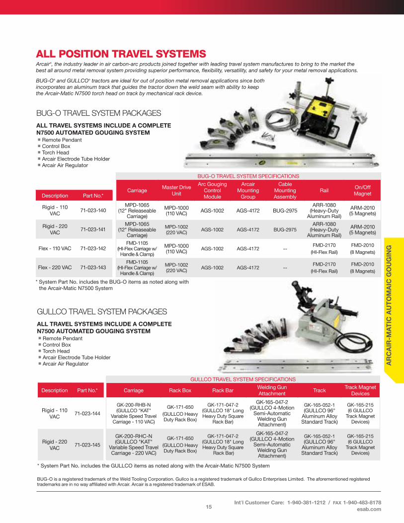
ALL POSITION TRAVEL SYSTEMSArcair®, the industry leader in air carbon-arc products joined together with leading travel system manufactures to bring to the market the best all around metal removal system providing superior performance, flexibility, versatility, and safety for your metal removal applications.
BUG-O® and GULLCO® tractors are ideal for out of position metal removal applications since both incorporates an aluminum track that guides the tractor down the weld seam with ability to keep the Arcair-Matic N7500 torch head on track by mechanical rack device.
GULLCO TRAVEL SYSTEM PACKAGES
ALL TRAVEL SYSTEMS INCLUDE A COMPLETE N7500 AUTOMATED GOUGING SYSTEMn Remote Pendantn Control Boxn Torch Headn Arcair Electrode Tube Holdern Arcair Air Regulator
BUG-O TRAVEL SYSTEM SPECIFICATIONS
CarriageMaster Drive
Unit
Arc Gouging Control Module
Arcair Mounting
Group
Cable Mounting Assembly
RailOn/Off Magnet
MPD-1065 (12" Releaseable
Carriage)
MPD-1000 (110 VAC) AGS-1002 AGS-4172 BUG-2975
ARR-1080 (Heavy-Duty
Aluminum Rail)
ARM-2010 (5 Magnets)
MPD-1065 (12" Releaseable
Carriage)
MPD-1002 (220 VAC) AGS-1002 AGS-4172 BUG-2975
ARR-1080 (Heavy-Duty
Aluminum Rail)
ARM-2010 (5 Magnets)
FMD-1105 (HI-Flex Carriage w/
Handle & Clamp)
MPD-1000 (110 VAC) AGS-1002 AGS-4172 --
FMD-2170(HI-Flex Rail)
FMD-2010(8 Magnets)
FMD-1105 (HI-Flex Carriage w/
Handle & Clamp)
MPD-1002 (220 VAC) AGS-1002 AGS-4172 --
FMD-2170(HI-Flex Rail)
FMD-2010(8 Magnets)
Description Part No .*
Rigid - 110 VAC
71-023-140
Rigid - 220 VAC
71-023-141
Flex - 110 VAC 71-023-142
Flex - 220 VAC 71-023-143
Description Part No .*
Rigid - 110 VAC
71-023-144
Rigid - 220 VAC
71-023-145
GULLCO TRAVEL SYSTEM SPECIFICATIONS
Carriage Rack Box Rack BarWelding Gun Attachment
TrackTrack Magnet
Devices
GK-200-RHB-N (GULLCO "KAT"
Variable Speed Travel Carriage - 110 VAC)
GK-171-650(GULLCO Heavy Duty Rack Box)
GK-171-047-2 (GULLCO 18" Long Heavy Duty Square
Rack Bar)
GK-165-047-2 (GULLCO 4-Motion
Semi-Automatic Welding Gun Attachment)
GK-165-052-1 (GULLCO 96"
Aluminum Alloy Standard Track)
GK-165-215 (6 GULLCO
Track Magnet Devices)
GK-200-RHC-N (GULLCO "KAT"
Variable Speed Travel Carriage - 220 VAC)
GK-171-650(GULLCO Heavy Duty Rack Box)
GK-171-047-2 (GULLCO 18" Long Heavy Duty Square
Rack Bar)
GK-165-047-2 (GULLCO 4-Motion
Semi-Automatic Welding Gun Attachment)
GK-165-052-1 (GULLCO 96"
Aluminum Alloy Standard Track)
GK-165-215 (6 GULLCO
Track Magnet Devices)
BUG-O TRAVEL SYSTEM PACKAGES
ALL TRAVEL SYSTEMS INCLUDE A COMPLETE N7500 AUTOMATED GOUGING SYSTEMn Remote Pendantn Control Boxn Torch Headn Arcair Electrode Tube Holdern Arcair Air Regulator
BUG-O is a registered trademark of the Weld Tooling Corporation . Gullco is a registered trademark of Gullco Enterprises Limited . The aforementioned registered trademarks are in no way affiliated with Arcair . Arcair is a registered trademark of ESAB .
* System Part No . includes the BUG-O items as noted along with the Arcair-Matic N7500 System
* System Part No . includes the GULLCO items as noted along with the Arcair-Matic N7500 System
15
AR
CA
IR-M
AT
IC A
UT
OM
AIC
GO
UG
ING
Int’l Customer Care: 1-940-381-1212 / fax 1-940-483-8178esab.com

STRAIGHT LINE FLAT POSITION CARRIAGETITAN TRAVEL SYSTEM PACKAGESFor metal removal applications in the flat position only, Arcair offers a machine carriage system that can carry the complete Arcair-Matic N7500 system and can be easily lifted on and off the work surface with an overhead crane . The track section consists of a steel “T” bar, machined on each end to permit joining additional sections easily . The same machine carriage can come with “outrigger” wheels to guide the carriage down the work surface, ideal for bridge girder back-gouging applications .
ALL TRAVEL SYSTEMS INCLUDE A COMPLETE N7500 AUTOMATED GOUGING SYSTEMn Remote Pendant (72-008-020)n Control Box (72-008-021)n Torch Head (05-124-001)n Arcair Electrode Tube Holder (94-893-082)n Arcair Air Regulator (71-000-073)
With the exception of the Power Communication Cable Assembly, all other System Cable Assemblies, 110V AC Power Cable, Pendant Cable, Motor Cable, DC Power Cable, and Air Hose Assemblies are included .
ARCAIR TITAN TRAVEL SYSTEM SPECIFICATIONSHorizontal Rack Bar
Vertical Rack Bar
Outrigger Wheel Pkg
TrackPointer
AssemblyMagnet
SupportsCable-Hose
ClampLift Bracket
71-099-073 71-099-074 –
71-022-501 (Arcair 10 ft
"T" Steel Track Section)
71-022-50271-022-504(3 Magnets)
71-022-506 94-111-168
71-099-073 71-099-074 80345 – – – 71-022-506 94-111-168
Description Part No .*
Titan Machine Carriage System
Package with Track - 110 VAC
71-022-704
Titan Machine Carriage System Package
w/ Outrigger Wheel Package - 110 VAC
71-022-705
TITAN WITH OUTRIGGER WHEEL PACKAGE
* System Part No . includes the items as noted along with the Arcair-Matic N7500 System
16
AR
CA
IR-M
AT
IC A
UT
OM
AIC
GO
UG
ING
U.S. Customer Care: 1-800-426-1888 / fax 1-800-535-0557 Canada Customer Care: 1-905-827-4515 / fax 1-800-588-1714
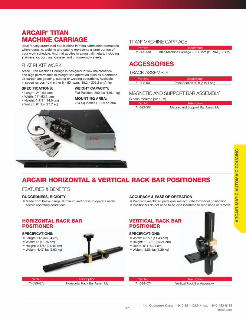
ARCAIR HORIZONTAL & VERTICAL RACK BAR POSITIONERSFEATURES & BENEFITS
RUGGEDNESS, RIGIDITYn Made from heavy gauge aluminum and brass to operate under
severe operating conditions
ACCURACY & EASE OF OPERATIONn Precision machined parts ensures accurate torch/tool positioningn Positioners do not need to be disassembled to reposition or remove
VERTICAL RACK BAR POSITIONER
SPECIFICATIONS: n Width: 4-1/2" (11 .43 cm) n Height: 13-7/8" (35 .24 cm) n Depth: 6" (15 .24 cm)n Weight: 3 .06 lbs (1 .39 kg)
HORIZONTAL RACK BAR POSITIONER
SPECIFICATIONS:n Length: 26" (66 .04 cm)n Width: 4" (10 .16 cm)n Height: 9-5/8" (24 .45 cm)n Weight: 4 .47 lbs (2 .02 kg)
Part No . Description71-099-073 Horizontal Rack Bar Assembly
Part No . Description71-099-074 Vertical Rack Bar Assembly
ARCAIR® TITAN MACHINE CARRIAGEIdeal for any automated applications in metal fabrication operations where gouging, welding and cutting represents a large portion of your work schedule . And that applies to almost all metals, including stainless, carbon, manganese, and chrome-moly steels .
FLAT PLATE WORKArcair Titan Machine Carriage is designed for low maintenance and high performance in straight line operation such as automated air-carbon arc gouging, cutting or welding operations . Available in speed ranges from either 6 – 80 i .p .m . (15 .2 – 203 .2 cm/min)
SPECIFICATIONS: n Length: 24" (61 cm)n Width: 21" (53 .3 cm)n Height: 5-7/8" (14 .9 cm)n Weight: 61 lbs (27 .7 kg)
WEIGHT CAPACITY: Flat Position: 300 lbs (136 .1 kg)
MOUNTING AREA: 254 Sq inches (1,639 sq cm)
TITAN® MACHINE CARRIAGEPart No . Description
71-022-501 Titan Machine Carriage - 6-80 ipm (110 VAC, 60 Hz)
ACCESSORIESTRACK ASSEMBLY
Part No . Description71-022-502 Track Section 10 ft (3 m) Long
MAGNETIC AND SUPPORT BAR ASSEMBLY (3 each required per 10 ft)
Part No . Description71-022-504 Magnet and Support Bar Assembly
17
AR
CA
IR-M
AT
IC A
UT
OM
AIC
GO
UG
ING
Int’l Customer Care: 1-940-381-1212 / fax 1-940-483-8178esab.com

SL
ICE
SLICE® EXOTHERMIC CUTTING SYSTEMFEATURES & BENEFITS
VERSATILE - UNLIKE ANY OTHER CUTTING TECHNOLOGYn Cuts right through hard-to-cut materials
– Mild, stainless steel and alloy steels– Cast iron– Aluminum, magnesium and other non ferrous metals– Slag and refractory materials– Pierces through concrete or brick
FAST CUTTING SPEEDSn No-preheat requiredn Cut sooner and finish every job faster
COMFORTABLE AND EASY TO USEn Pistol grip style handlen Lightweight shield to protect the operator from heat and sparksn Lever operated oxygen control
CARRY ALL CONVENIENCEn Several portable SLICE packs to choose from
– Utility Pack– Battery Pack– Industrial Pack– Complete Pack
WATCH A VIDEO OF THE ARCAIR SLICE PACK IN ACTION AT WWW.ARCAIRSLICE.COM
USE 1/4" & 3/8" DIAMETER of cutting rods by simply changing the collet nut and collet chuck
LIGHTWEIGHT SHIELD to help protect the operator from heat and sparks
INDUSTRIAL GRADE OXYGEN HOSE 10 ft (3 m) length is standard
PISTOL GRIP designed handle is comfortable and easy to use
EASY TO SQUEEZE LEVER on the handle for easy oxygen control
SLICE EXOTHERMIC CUTTING TORCH
SLICE Head and Body are brazed together and are thoroughly cleaned to be oil free for use with oxygen
SPARK ARRESTORS are part of every SLICE torch for safety reasons
18U.S. Customer Care: 1-800-426-1888 / fax 1-800-535-0557 Canada Customer Care: 1-905-827-4515 / fax 1-800-588-1714

SL
ICE
TIPS FOR USING SLICE® EXOTHERMIC CUTTING EQUIPMENT
TIPS FOR CUTTINGCutting procedures will vary from job to job . Study the cutting rates chart for specific cutting speeds .
Normal cutting is done by using a drag technique . Once the rod is in contact with the piece to be cut, drag the rod in the direction of the cut . If the operator can’t see the kerf, the speed of cut is too fast . If the rod is being used too rapidly the progress of the cut is too slow and the rod is being used without cutting . REMEMBER, the cutting rods consume as long as the oxygen is flowing . Maintain the proper travel speed at all times . NOTE: Use a sawing motion when material to be cut is thicker than 1-1/2 to 2 inches to ensure a complete melt through .
Use a smooth motion to complete the cut . Be careful not to hit nearby material with the rod when cutting in “close quarters .” After completing the cut, release the oxygen control lever in the handle . THE CUTTING ROD WILL CONTINUE TO BURN AS LONG AS OXYGEN IS SUPPLIED . Hold the torch safely away from you until the rod cools .
TIPS FOR PIERCING SURFACESThe SLICE Torch can be used to pierce solids . Special procedures must be used when piercing . When piercing, use a collet extension (and shield) . This extension adds life to the torch and hand shield, and greatly improves operator safety and comfort . Always hold the torch at arm’s length and wear plenty of protective clothing, eye and ear protection . Cutting rods can get stuck inside the pierced hole . If possible, remove the cutting rod from the hole before releasing the oxygen lever .
With any thermal cutting equipment blowback is most likely to occur when the user is piercing holes . Cutting rods may burn unevenly . Slowly swirl the cutting rod as it enters a pierced hole . Cutting rods may burn out on the sides . Correct the problem by removing the cutting rod from the pierce point, shut the oxygen off, and replace the cutting rod .
To pierce follow these steps:n Strike cutting rod on striker .n Hold torch at arm’s length .n Keep the cutting rod at a 90° angle (perpendicular) to the pierce point .n Slowly push cutting rod in at pierce point until you’re at proper depth
or until you’ve achieved burn through .The pierce procedure is also used to cut concrete . By piercing a series of holes where a user wants to cut concrete, the concrete becomes easier to fracture . This helps reduce the time it would take to actually cut the concrete .
OXYGEN USAGEThis cutting process uses standard industrial grade oxygen to support the exothermic reaction and to remove the molten metal . All SLICE equipment uses standard oxygen fittings . The most commonly recommended operating pressure is 80 psi . Applications such as cutting material sections 3" and thicker might require higher operating pressures . Pressures as low as 40 psi have been used to perform operations such as washing off rivet heads and scarfing out small cracks for repair .
The oxygen consumption rate for the SLICE cutting rods at 80 psi is 7 to 7 .5 cfm for the 1/4" diameter cutting rods and 11 to 12 cfm for the 3/8" diameter cutting rods . This rate will vary if a different operating pressure is used .
ROD BURNTIMEListed are the approximate burntimes for the various SLICE rod diameters and lengths:1/4" X 22" (6 .4 X 559 mm) . . . . . . . . . . 40 - 45 seconds1/4" X 44" (6 .4 X 1118 mm) . . . . . . . . . 80 - 90 seconds3/8" X 18" (9 .5 X 457 mm) . . . . . . . . . 30 - 35 seconds3/8" X 36" (9 .5 X 914 mm) . . . . . . . . . 60 - 70 seconds
APPLICATION DATAThe best techniques for the SLICE equipment will change from job to job . The enclosed charts present the results of extensive testing of the SLICE Torch . Four things contribute to good cutting - 1) Electrical current . 2) Type of material being cut . 3) Environmental conditions . 4) Experience of the operator(s) .
These data result from studies of the first two (2) items in this list . Since data were collected in a LABORATORY, actual results obtained will vary because of changes in the environment . Too, these tests were conducted by highly experienced users . The way in which you use the SLICE Torch will also cause your results to vary .
In any application, some adjustments in operating conditions are necessary . The charts are presented only as a guideline . Results will vary . You can approximate these results by using the data presented as a starting point, then adjusting for your job .
Here is a sample of some cutting rates that can be obtained using the SLICE Equipment . Cutting rates in this chart were obtained using 80 PSI oxygen pressure, battery ignition (no power cutting) and 1/4" x 22" cutting rods . These cutting rates will vary when using different rods, when cutting with power or using a different oxygen pressure . This chart does not represent all materials SLICE will cut nor all thicknesses used in fabrication . When cutting composite materials or metals not listed, locate the listed type that most closely matches the metal to be cut . This information is only meant as a reference to the efficiency and versatility that a user can realize using the SLICE Equipment .
CUTTING RATESMaterial
Being CutThickness Cut/in Rod Cut Speed
in . cm in . cm in/min cm/min
Carbon Steel
1/8 .318 2 .25 5 .7 72 1831/4 .635 1 .50 3 .8 52 1323/8 .953 1 .38 3 .5 42 1061/2 1 .27 1 .25 3 .2 35 893/4 1 .91 0 .75 1 .9 22 56
Stainless Steel
1/8 .318 2 .00 5 .1 65 1651/4 .635 1 .13 2 .9 36 91
Aluminum1/4 .635 1 .75 4 .4 58 1473/8 .953 1 .25 3 .2 38 973/4 1 .91 0 .75 1 .9 23 58
This data is the result of averaging lab tests . The actual results will vary .
19Int’l Customer Care: 1-940-381-1212 / fax 1-940-483-8178
esab.com

SL
ICE
SLICE EXOTHERMIC CUTTING RODSSPECIALLY DESIGNED CUTTING RODn One piece patented construction maintains the balance necessary to sustain the
exothermic reactionn Cutting rod sustains the burn without constant electrical power once ignited
Uncoated Part No
Flux Coated Part No .
Description
43-049-002 42-049-002 1/4" x 22" (6 .4 mm x 55 .9 cm) 25 each /carton
43-049-003 42-049-003 1/4" x 22" (6 .4 mm x 55 .9 cm) 100 each /carton
43-049-005 – 1/4" x 44" (6 .4 mm x 111 .8 cm) 25 each /carton
43-049-007 42-049-005 3/8" x 18" (9 .5 mm x 45 .7 cm) 50 each / carton
43-049-009 – 3/8" x 36" (9 .5 mm x 91 .4 cm) 25 each / carton
SLICE UTILITY PACKIncludes a rugged tool box carrying case . Power connections (12 volt battery only), tong style battery clamps makes power connection quick and easy . Industrial oxygen hose connected to the torch; industry standard “green” hose supplies the torch with oxygen, and standard fittings used to connect to oxygen regulators .
SYSTEM INCLUDES:n Tool Box (94-134-049)n SLICE Torch Assembly (03-003-001)n SLICE Striker Assembly (72-012-002)n Collet Extension Assembly – 6" (15 .24 cm) (94-168-023)n Extension Shield (94-777-111)n Clamp (Red) (96-168-035)n Clamp (Black) (96-168-036)
Part . No . Description63-991-026 SLICE Utility Pack
SLICE TORCH FOR USE WHEN CUTTING WITH WELDING CURRENT (<200 amps)
Part . No . Description03-003-000 SLICE Torch Assembly
SLICE BATTERY PACKIncludes a rugged tool box carrying case . Power connections twist-lock style connection; easy to connect to battery box assembly for both torch and striker and color coded connectors . Industrial oxygen hose connected to the torch; industry standard “green” hose supplies the torch with oxygen, standard fittings used to connect to oxygen regulators, and color coded connections .
SYSTEM INCLUDES:n Tool Box (94-134-047)n SLICE Torch Assembly (03-003-006)n SLICE Striker Assembly (72-012-002)n Battery Box Assembly (96-076-021)n Cutting Rod 1/4" x 22" (qty 25) (43-049-002)n Collet Extension Assembly – 6" (15 .24 cm) (94-168-023)n Extension Shield (94-777-111)n Charging Cable – 110 VAC/60 Hz (96-130-297)n Charging Cable – 220 VAC/50 Hz (96-130-296)
Part No . Description63-991-003 SLICE Battery Pack 110 VAC @60 Hz63-991-007 SLICE Battery Pack 220 VAC @50 Hz
Part No . Description94-463-032 3/8" Collet Conversion Kit
20U.S. Customer Care: 1-800-426-1888 / fax 1-800-535-0557 Canada Customer Care: 1-905-827-4515 / fax 1-800-588-1714

SL
ICE
SLICE INDUSTRIAL PACKVersatility for industrial type applications . Industrial cart capable of carrying a 9" diameter oxygen cylinder . Packed with the basic items needed to do a cutting job; SLICE Torch Assembly – 10 ft leads, striker assembly, oxygen regulator, battery charger, and cutting rod holder . Industrial oxygen hose connected to the torch; industry standard “green” hose supplies the torch with oxygen and standard fittings used to connect to oxygen regulators .
SYSTEM INCLUDES:n Storage Casen SLICE Torch Assembly (03-003-001)n SLICE Striker Assembly (72-012-002)n Battery Charger (96-156-003)n Cutting Rod 1/4" x 22"
(qty 25) (43-049-002)n Collet Extension Assembly –
6" (15 .24 cm) (94-168-023)n Extension Shield (94-777-111)n Rod Holdern Outfit Wrench – Hose Nut and
Regulator Nutn Outfit Wrench – Oxygen Hose Nut
and Male Adaptern Clamp Assembly (Red) (96-168-035)n Clamp Assembly (Black) (96-168-036)n 12" Rubber Tie Down
Part . No . Description63-991-021 SLICE Industrial Pack
SLICE COMPLETE PACKRugged aluminum carrying case; packed with the basic items needed to do a cutting job . Self-contained cutting system lends itself well to the emergency type cutting situations where seconds count . Complete unit weighs 75 lbs (34 kg) . Storage compartment with hinged door for parts storage during transportation . Power connections twist-lock style connection; easy to connect to battery box assembly for both torch and striker and color coded connectors . Industrial oxygen hose connected to the torch; industry standard “green” hose supplies the torch with oxygen . Standard fittings used to connect to oxygen regulators .
SYSTEM INCLUDES:n Aluminum Case Assembly (94-134-034)n SLICE Torch Assembly (03-003-006)n SLICE Striker Assembly (72-012-002)n Battery Box Assembly (96-076-021)n Cutting Rod 1/4" x 22" (qty 25) (43-049-002)n Collet Extension Assembly – 6" (15 .24 cm) (94-168-023)n Extension Shield (94-777-111)n Spacern 10" Rubber Tie Downn Oxygen Regulator (0799-1607)n Oxygen Cylinder 55 cu ft (94-208-002)n Charging Cable – 110 VAC/60 Hz (96-130-297)n Charging Cable – 220 VAC/50 Hz (96-130-296)n Outfit Wrench – Hose Nut and Regulator Nutn Outfit Wrench – Oxygen Hose Nut and Male Adapter
Part . No . Description63-991-002 SLICE Complete Pack 110 VAC @60 Hz63-991-005 SLICE Complete Pack 220 VAC @50 Hz
NOTE: 220 VAC system does not include oxygen cylinder and regulator
21Int’l Customer Care: 1-940-381-1212 / fax 1-940-483-8178
esab.com

UN
DE
RW
AT
ER
SEA TORCH® “COMBINATION TORCH”Underwater Cutting Torch & Welding Torch
FEATURES & BENEFITS
ONE PIECE BODY CONSTRUCTIONn Fully insulated electrically for safety
in normal operationn Prohibits oxygen leakage in the torch body n Bright orange for high visibility to the diver
COMBINATION TORCHn Torch can be used for oxygen-arc cuttingn Underwater welding
TAPERED COLLET BODYn Brings the bare surface of an electrode into
contact for the entire length of the colletn Solid grip and increased contact area decreases
the risk of arcing between the collet and electrode
EQUIPPED WITH A SPARK ARRESTORn Spark arrestor located behind the collet for
safe operationn Ball check valve in the torch handle gives
additional protection
SPECIFICATIONS: n Equipped with 10 ft (3 m) power cablen Length: 8-3/4" (22 .2 cm)n Weight: 4 .5 lbs (2 .04 kg) with cable
Part . No . Description14-050-124 Sea Torch 5/16" (7 .9 mm) Cutting Collet14-050-126 Sea Torch 3/8" (9 .5 mm) Cutting Collet
UNDERWATER CUTTING ELECTRODESFEATURES & BENEFITS
OXYGEN-ARC AND EXOTHERMIC CUTTING ELECTRODESn Oxygen-arc cutting electrodes requires current to be present
during the cutting processn Exothermic cutting electrodes only require current to ignite the
electrode and once ignited the rod will continue to burn as long as there is oxygen flowing
WATER-PROOF COATINGn All cutting electrodes are coated
with a water-proof coating
SEA-CUT® CUTTING ELECTRODES“Oxygen-Arc Process” (50 per carton)
Part No . Diameter Length
42-059-007 5/16" (7 .9 mm) - .113" ID (2 .9 mm) 14" (45 .7 cm)
SEA-JET® CUTTING ELECTRODES“Exothermic Process” (50 per carton)
Part No . Diameter Length42-066-006 3/8" (9 .5 mm) 18" (45 .7 cm)
TUFF-COTE® CUTTING ELECTRODES FLUX COATED “Oxygen-Arc Process” (50 per carton)
Part No . Diameter Length42-059-008 5/16" (7 .9 mm) - .113" ID (2 .9 mm) 14" (45 .7 cm)
SEA-DRAGON™ CUTTING ELECTRODES “Exothermic Process” (50 per carton)
Part No . Diameter Length42-075-005 3/8" (9 .5 mm) 18" (45 .7 cm)
22U.S. Customer Care: 1-800-426-1888 / fax 1-800-535-0557 Canada Customer Care: 1-905-827-4515 / fax 1-800-588-1714

UN
DE
RW
AT
ER
UNDERWATER WELDING ELECTRODESFEATURES & BENEFITS
EXCELLENT BEAD CONTOURn All position, flux coated SMAW electrode
FILLET WELDS ARE FLAT WITH GOOD BASE METAL WETTINGn Helps keep undercut to a minimum
EASY SLAG REMOVALn Keeps chipping and grinding to a minimumn Lower risk of slag inclusions
PRODUCED WELDS WHICH PASS BEND AND X-RAY REQUIREMENTSn As defined by the AWS D3 .6 specification for underwater welding
UNDERWATER GOUGING ELECTRODES
SEA-WELD® WELDING ELECTRODESPart No . Electrode Size Per Carton
42-024-002 1/8" (3 .2 mm) x 14" (35 .6 cm) 15042-984-004 5/32" (4 .0 mm) x 14" (35 .6 cm) 10042-034-007 3/16" (4 .8 mm) x 14" (35 .6 cm) 75
ARCWATER® GOUGING ELECTRODES(50 Per carton)
Part No . Diameter Amperage Length42-059-006 5/16" (7 .9 mm) 350 - 450 9" (22 .9 cm)
SEA-STINGER® II TORCHUnderwater Welding Torch
FEATURES & BENEFITS
LIGHTWEIGHT AND DURABLEn Proven design that gives the diver-welder an easy to use
electrode holdern Repairable replaceable cable and internal parts extend its service life
ACCEPTS SEVERAL DIFFERENT DIAMETER OF WELDING ELECTRODESn 1/8" (3 .2 mm), 5/32" (4 .0 mm) and 3/16" (4 .8 mm) welding electrodes
SPECIFICATIONS: n Equipped with 10 ft (3 m) Power Cablen Length: 6" (15 .24 cm)n Weight: 3 .65 lbs (1 .66 kg) with cable
Part . No . Description14-050-128 Sea-Stinger II Torch
ARCWATER® II TORCHUnderwater Gouging Torch
FEATURES & BENEFITS
DESIGNED FOR UNDERWATER GOUGING OPERATIONSn Similar to gouging above water with
the exception of using a high velocity of pressurized water in place of compressed air
n Uses sea water at 90 psi (6 .32 kg/cm2 or 620 kPa) over the pressure at the depth of use
n Minimum water flow rate of 3 .5 gallons (13 .25 liters) per minute required
OXYGEN FREEn Eliminates the risk of hydrogen gas pocket
explosions
EASY TO USEn Handle can be used left or right handed diversUsed out-of position
CONVERTS INTO A WELDING TORCH EASILYn Simply change out the collet to except welding
electrodes
SPECIFICATIONS: n Equipped with 10 ft (3 m) Power Cablen Length: 9-3/4" (22 .2 cm)n Weight: 5 .5 lbs (2 .5 kg)
Part . No . Description14-050-127 Arcwater II Torch
23Int’l Customer Care: 1-940-381-1212 / fax 1-940-483-8178
esab.com
PR
OT
EX
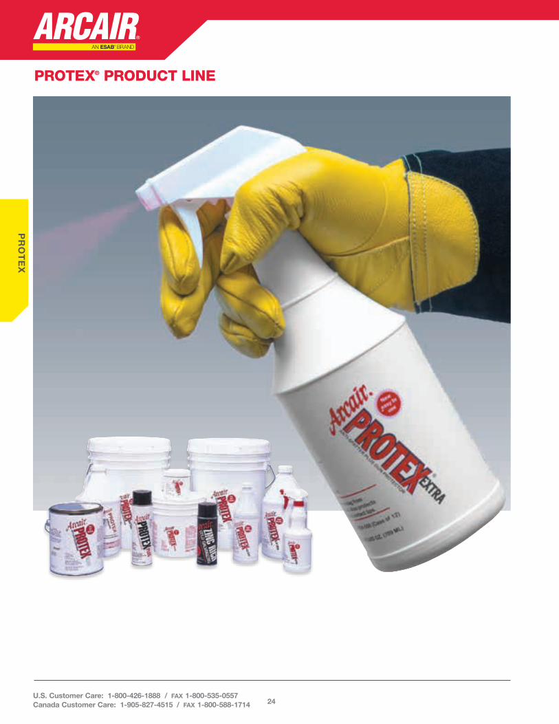
PROTEX® PRODUCT LINE
24U.S. Customer Care: 1-800-426-1888 / fax 1-800-535-0557 Canada Customer Care: 1-905-827-4515 / fax 1-800-588-1714
PR
OT
EX
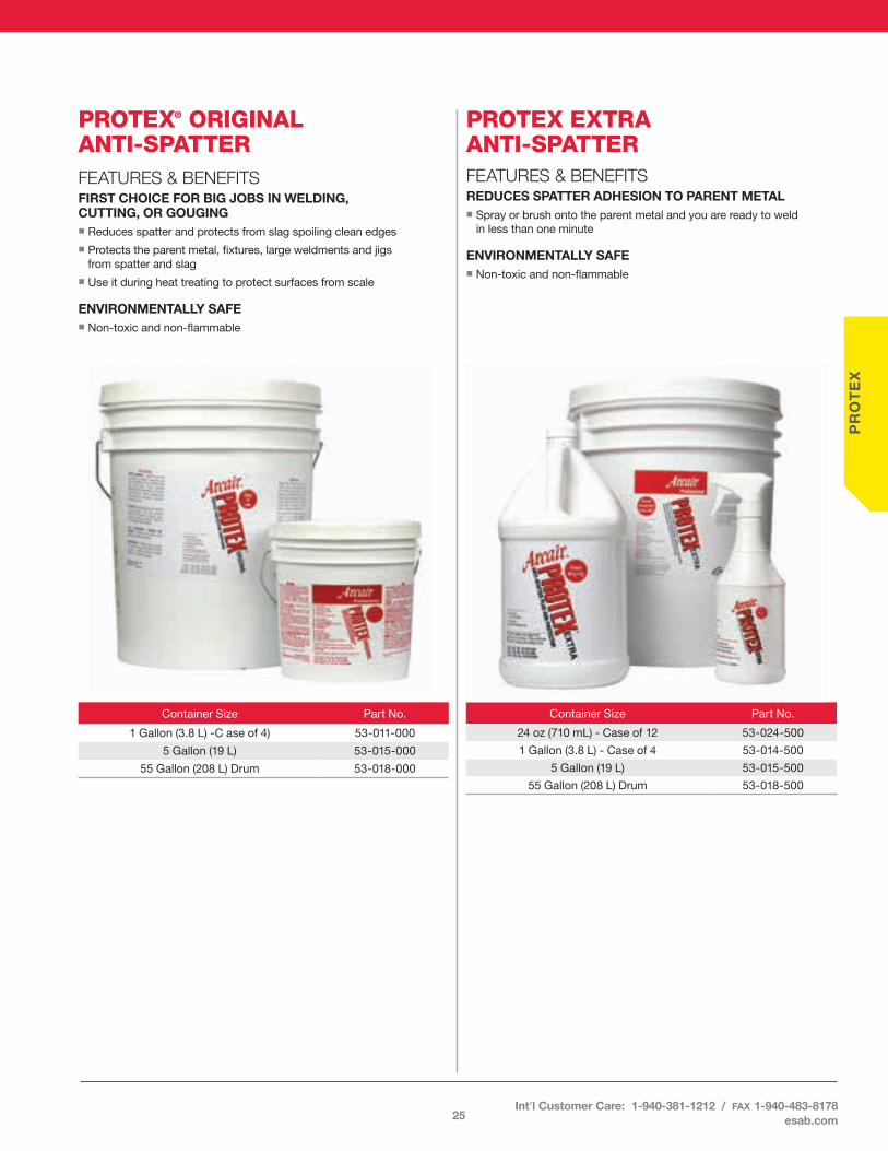
PROTEX® ORIGINAL ANTI-SPATTERFEATURES & BENEFITSFIRST CHOICE FOR BIG JOBS IN WELDING, CUTTING, OR GOUGINGn Reduces spatter and protects from slag spoiling clean edgesn Protects the parent metal, fixtures, large weldments and jigs
from spatter and slagn Use it during heat treating to protect surfaces from scale
ENVIRONMENTALLY SAFEn Non-toxic and non-flammable
PROTEX EXTRA ANTI-SPATTERFEATURES & BENEFITSREDUCES SPATTER ADHESION TO PARENT METALn Spray or brush onto the parent metal and you are ready to weld
in less than one minute
ENVIRONMENTALLY SAFEn Non-toxic and non-flammable
Container Size Part No .
1 Gallon (3 .8 L) -C ase of 4) 53-011-000
5 Gallon (19 L) 53-015-000
55 Gallon (208 L) Drum 53-018-000
Container Size Part No .
24 oz (710 mL) - Case of 12 53-024-500
1 Gallon (3 .8 L) - Case of 4 53-014-500
5 Gallon (19 L) 53-015-500
55 Gallon (208 L) Drum 53-018-500
25Int’l Customer Care: 1-940-381-1212 / fax 1-940-483-8178
esab.com

PR
OT
EX
PROTEX PLUS ANTI-SPATTERFEATURES & BENEFITSREDUCES ADHESION TO PARENT METALn Spray onto the parent metal to reduce
spatter or slag from adhering
ENVIRONMENTALLY SAFEn An aerosol anti-spattern Contains no chlorinated solvents,
fluorocarbons, silicones
PROTEX ZINC RICH COLD GALVANIZINGFEATURES & BENEFITSCORROSION PROTECTIONn Its zinc content “sacrifices” itself to any
metal higher (nobler) than zinc in the chemistry’s periodic table such as steel
n Forms a chemical bond to the parent metal
PROTEX CLEAR ANTI-SPATTERFEATURES & BENEFITSPROTECTS SURFACES FROM SPATTER, SLAG, AND SCALEn Dries clear and provides a tough finishn Spray or brush onto the surface
PROTECTS AGAINST RUSTn Latex base anti-spatter compound that coats the surface and
can be left on for lasting protectionn Remove with industrial solvent or an ammonia solution
Container Size Part No .
1 Gallon (3 .8 L) - Case of 4 53-014-201
5 Gallon (19 L) 53-015-201
55 Gallon (208 L) Drum 53-018-201
Container Size Part No .
16 oz (473 mL) Can - Case of 12 57-031-002
Container Size Part No .
16 oz (473 mL) Can - Case of 12 57-021-106
26U.S. Customer Care: 1-800-426-1888 / fax 1-800-535-0557 Canada Customer Care: 1-905-827-4515 / fax 1-800-588-1714

PR
OT
EX
Protex AlcleanFEATURES & BENEFITSREMOVES OXIDES, DIRT AND GRIME FROM ALUMINUM PLATE, CASTINGS AND JOINT AREAS PRIOR TO WELDINGn Spray or brush on large areas
Note: may turn 2000 Series aluminum black .
Container Size Part No .
1 Quart (946 mL) - Case of 12 57-021-200
1 Gallon (3 .8 L) - Case of 4 57-014-000
Container Size Part No .
16 oz (454 gr) Jar - Case of 12 57-021-105
Protex Tip-Dip Anti-SpatterFEATURES & BENEFITSPROTECTS SPATTER BUILD UP ON GMAW NOZZLES AND CONTACT TIPSn High heat resistance to minimize spatter build-up
Note: Allow nozzles to cool below red heat before dipping (ignition may occur above 1000˚F)
ENVIRONMENTALLY SAFEn Non-toxic
27Int’l Customer Care: 1-940-381-1212 / fax 1-940-483-8178
esab.com
LIMITED WARRANTY: ESAB warrants that its products will be free of defects in workmanship or material . Should any failure to conform to this warranty appear within the time period applicable to the ESAB products as stated below, ESAB shall, upon notification thereof and substantiation that the product has been stored, installed, operated, and maintained in accordance with ESAB’s specifications, instructions, recommendations and recognized standard industry practice, and not subject to abuse, misuse, neglect, alteration, accident, improper care and/or maintenance including lack of lubrication and protection from the elements, use of non ESAB genuine parts including consumables; will correct such defects by suitable repair or replacement, at ESAB’s sole option, of any components or parts of the product determined by ESAB to be defective .
THIS WARRANTY IS EXCLUSIVE AND IS IN LIEU OF ANY WARRANTY OF MERCHANTABILITY OR FITNESS FOR A PARTICULAR PURPOSE.
LIMITATION OF LIABILITY: ESAB shall not under any circumstances be liable for special or consequential damages, such as, but not limited to, damage or loss of purchased or replacement goods, or claims of customers of distributor (hereinafter “Purchaser”) for service interruption .
The remedies of the Purchaser set forth herein are exclusive and the liability of ESAB with respect to any contract, or anything done in connection therewith such as the performance or breach thereof, or from the manufacture, sale, delivery, resale, or use of any goods covered by or furnished by ESAB whether arising out of contract, negligence, strict tort, or under any warranty, or otherwise, shall not, except as expressly provided herein, exceed the price of the goods upon which such liability is based .
THIS WARRANTY BECOMES INVALID IF REPLACEMENT PARTS OR ACCESSORIES ARE USED WHICH MAY IMPAIR THE SAFETY OR PERFORMANCE OF ANY ESAB PRODUCT.
THIS WARRANTY IS INVALID IF THE PRODUCT IS SOLD BY NON-AUTHORIZED PERSONS.
The warranty is effective for the time stated below beginning on the date that the authorized distributor delivers the products to the Purchaser . Notwithstanding the foregoing, in no event shall the warranty period extend more than the time stated plus 1 year from the date ESAB delivered the product to the authorized distributor .
ESAB limited warranty shall not apply to: Consumable Parts for MIG, TIG, Plasma welding, Plasma cutting and Oxyfuel torches, O-rings, fuses, filters or other parts that fail due to normal wear.
* Warranty repairs or replacement claims under this limited warranty must be submitted by an authorized ESAB repair facility within thirty (30) days of the repair .
* No employee, agent, or representative of ESAB is authorized to change this warranty in any way or grant any other warranty, and ESAB shall not be bound by any such attempt . Correction of non-conformities, in the manner and time provided herein, constitutes fulfillment of ESAB’s obligations to purchaser with respect to the product .
* This warranty is void, and seller bears no liability hereunder, if purchaser used replacement parts or accessories which, in ESAB’s sole judgment, impaired the safety or performance of any ESAB product . Purchaser’s rights under this warranty are void if the product is sold to purchaser by unauthorized persons .
WARRANTY
1 YEAR PARTS AND LABOR UNLESS SPECIFIED Arcair® N7500 (No Labor)
30 DAYS PARTS / NO LABOR All Other Products
28U.S. Customer Care: 1-800-426-1888 / fax 1-800-535-0557 Canada Customer Care: 1-905-827-4515 / fax 1-800-588-1714
WA
RR
AN
TY

Form No . 89-1501 (02/01/16) © 2016 ESAB esab .com Printed in U .S .A .
U.S. Customer Care: 800-426-1888 / fax 800-535-0557 • Canada Customer Care: 905-827-4515 / fax 800-588-1714 International Customer Care: 940-381-1212 / fax 940-483-8178 • CIGWELD Customer Care: 1 300-654-674 / fax 61-3-9474-7391
ISO 9001REGISTERED FIRM
The Quality System of ESAB at our Denton, Roanoke,
West Lebanon and Hermosillo locations is registered to meet the requirements of ISO 9001