Industrial Carbon Management Initiative (ICMI) Project ... Library/Events/2012/CO2 Capture... ·...
33
July 2012 Industrial Carbon Management Initiative (ICMI) Project Review & Status Acknowledgements: …too many names to list… This report was prepared as an account of work sponsored by an agency of the United States Government. Neither the United States Government nor any agency thereof, nor any of their employees, makes any warranty, express or implied, or assumes any legal liability or responsibility for the accuracy, completeness, or usefulness of any information, apparatus, product, or process disclosed, or represents that its use would not infringe privately owned rights. Reference herein to any specific commercial product, process, or service by trade name,trademark, manufacturer, or otherwise does not necessarily constitute or imply its endorsement, recommendation, or favoring by the United States Government or any agency thereof. The views and opinions of authors expressed herein do not necessarily state or reflect those of the United States Government or any agency thereof.
Transcript of Industrial Carbon Management Initiative (ICMI) Project ... Library/Events/2012/CO2 Capture... ·...

July 2012
Industrial Carbon Management Initiative (ICMI) Project Review & Status
Acknowledgements: …too many names to list…
This report was prepared as an account of work sponsored by an agency of the United States Government. Neither the United States Government nor any agency thereof, nor any of their employees, makes any warranty, express or implied, or assumes any legal liability or responsibility for the accuracy, completeness, or usefulness of any information, apparatus, product, or process disclosed, or represents that its use would not infringe privately owned rights. Reference herein to any specific commercial product, process, or service by trade name,trademark, manufacturer, or otherwise does not necessarily constitute or imply its endorsement, recommendation, or favoring by the United States Government or any agency thereof. The views and opinions of authors expressed herein do not necessarily state or reflect those of the United States Government or any agency thereof.

2
Industrial assessment and systems analysis
Carbon Capture Chemical Looping Combustion
CO2 & H2
CH3OH
Carbon Utilization Photocatalytic Conversion
Carbon Storage Depleted Shale Fields
CCUS for Industrial
Applications
ICMI Research areas Focus is on “industrial” applications: NG or coal boilers, process heat, chemical production, others. Technical results expected to benefit coal power as well.

3
Industrial assessment and systems analysis
Carbon Capture Chemical Looping Combustion
CO2 & H2
CH3OH
Carbon Utilization Photocatalytic Conversion
Carbon Storage Depleted Shale Fields
CCUS for Industrial
Applications
ICMI Research Areas Focus is on “industrial” applications: NG or coal boilers, process heat, chemical production, others. Technical results expected to benefit coal power as well.

4
High-potential Industrial Applications
• CL industrial boilers • CL for oil sands processing and production • CO2 sequestration in depleted shale gas reservoirs
ICMI Focus: Industrial Sources
Early industrial application…. …….leading to electric power applications.
Reference for CO2 Stationary Source Emissions by Category chart: DOE's Regional Carbon Sequestration Partnerships and NATCARB database.

5
0
20,000
40,000
60,000
80,000
100,000
120,000
140,000
0 20 40 60 80 100
CO2
Emis
sion
Per
Boi
ler
(ton
s/yr
)
Boiler Size - Thermal Input (MW)
~175 GW of capacityfor sizes > 60 MW
~63 GW of capacityfor 15-30 MW units
U.S. Industrial Boiler Market (Natural Gas)
• 43,000 boilers in the U.S. – More than 50% are smaller than 3 MWt
• CO2 emissions per boiler are comparable to some demonstration CCUS projects, or EOR wells
• Old infrastructure – For boilers > 3 MWt
• 47% > 40 yrs old • 76% > 30 yrs old
– Expected life 30 yrs • NOx requirements
– 30-80 ppm @ 3% O2
– Larger units are lower
Reference: Booz, Allen, Hamilton, Analysis of Fuel Flexibility Opportunities and Constraints in the U.S. Industrial Sector, Draft Report, March 7, 2007, DOE/EERE

6
CO2 Separation Issues for Industrial Boiler Applications
Technology Issues Flue-gas scrubbing (e.g. MEA) • Capital investment for add-on
• Chemical handling issues • Need economic cost studies
Membranes • Low pressure flue gas • Potentially poor energetics • Need economic cost studies
Oxy-fuel • Capital investment for ASU and exhaust gas recycle • NOx – O2 purity trade-offs • CO2 separation is simple • Need economic cost studies
Chemical Looping • Ultra-low NOx • CO2 separation is simple • Need economic cost studies • Need to validate technology

7
Where and how can chemical looping work? Industrial applications (includes NG, smaller scale)
Power applications (coal, 100+MW scale)
Attributes: Fuel (NG, solid fuels) Size Cost Performance System issues & configuration Attrition Material supply & handling Heat exchanger/integration Sensors and control Emissions Carrier cost/supply & re-use Components Hydrodynamics Heat transfer Size/cost Basic data Carrier capacity Carrier reaction rate w/oxygen Carrier reaction rate w/fuel Carrier degradation
Iterate with more information
ICMI work elements provide the data and analysis. Element 510 considered relevant industrial applications (next slides)

8
Defining the Application and Baseline for Economic Studies

9
Industry - Capture Technology Matrix PotentialProvenPreferredIn TestingCapture not Required
N1 Will not be suited to retrofit -- new plant onlyN2 Pre-combustion not suitable due to lower radiant propertiesN3 Oxyfuel with CO2 removal via solvent
N4 Post Combustion limited due to many point sourcesN5 Makes up majority of plants, ~70%N6 CO2 from fermentors only (no fuel) -- Produces relatively pure CO2
Che
mic
al
Solv
ent
Phys
ical
Sol
vent
Sorb
ent
Mem
bran
e
Car
bona
te
Loop
ing
Cry
ogen
ic
Oxy
fuel
Che
mic
al
Loop
ing
Com
bust
ion
Che
mic
al
Solv
ent
Phys
ical
Sol
vent
Sorb
ent
Mem
bran
e
Che
mic
al
Loop
ing
Ref
orm
ing
Process Heating - N4Steam/Utilities - N4Hydrogen ProductionFCC Regeneration
Cement Kiln - N2 N1
Traditional Blast Furnace - N5 N3 N3DRI
O&G ProcessingO&G Processing Steam/UtilitiesOil Sands Steam Production - SAGDOil Sands Processing - HydrogenOil Sands Processing - Steam
Bioethanol via fermentation - N6EthyleneSteam/Utilities
Kraft Mills - N5Steam and Heat
Hydrogen Production
Gas Separation/Post Combustion Oxyfuel Pre-Combustion
Refineries
Cement
Iron & Steel
Oil & Gas
Ethanol/Ethylene
Pulp & Paper
Ammonia/Fertilizer

10
Potential Chemical Looping Application
• Steam Production – In any industrial or
commercial facility where boilers are in use
– Oil Sands production & processing, especially Steam Assisted Gravity Drainage (SAGD) very attractive
– Oil & Gas production, especially where CO2 could be used for EOR
• Electric Power Generation – Need to fully characterize
size & complexity of the systems
– Analysis coordinated with NETL studies of power systems
Steam Chamber
Steam Injection
Oil Production Reservoir
Steam Injection
Oil Production
SAGD Process

11
Industrial Boiler Steam Conditions
• Oil Sands SAGD – Saturated steam at 1000 to 1600 psi (Sat temp: 550F to 610F = 290 to 320 C) – 500,000+ lb/hr steam rate – Fueled by natural gas (could consider pet coke)
• Oil & Gas Plant – Saturated steam at varying pressure levels (LP [~50 psi] & MP [~300 psi] typical) – Variable steam rate – Fueled by natural gas
• Refinery – Saturated steam up to 900 psi pressure levels – 500,000+ lb/hr steam rate – Fueled by refinery gas
• Recommendation for future systems analysis work – Evaluate steam generation at 300, 600, 900 and 1500 psi levels – Natural gas fuel – Compare to SAGD and other industrial / commercial steam systems
Very different than power applications

12
Establishing a baseline case for an industrial boiler application with capture

13
Site Description and Conditions
Elevation, (ft) 0 Barometric Pressure, MPa (psia) 0.10 (14.696) Design Ambient Temperature, Dry Bulb, °C (°F) 15 (59) Design Ambient Temperature, Wet Bulb,°C, (°F) 11 (51.5) Design Ambient Relative Humidity, % 60
• Unspecified location • Generic conditions based on ISO specifications • Site specific conditions can impact analysis, but
comparisons are valid as long as design conditions are consistent across cases

14
Fuel – Natural Gas Natural Gas Composition:
Component Volume Percentage
Methane CH4 93.1 Ethane C2H6 3.2 Propane C3H8 0.7 n-Butane C4H10 0.4 Carbon Dioxide CO2 1.0 Nitrogen N2 1.6
Total 100.0
LHV HHV kJ/kg 47,454 52,581 MJ/scm 34.71 38.46 Btu/lb 20,410 22,600 Btu/scf 932 1,032
Natural Gas Cost: Baseline Studies: $6.55/MMBtu, June 2007 dollars Updated Cost: $6.13/MMBtu, June 2011 dollars Assumes gas is delivered at 435 psig

15
Industrial Baseline Application Design • Steam Generator Capacity
– Case 1: 27,500 lb/hr (~10 MW Thermal) – Case 2: 275,000 lb/hr (~100 MW Thermal) – Steam is generated at 600 psi with 100°F of superheat – 80% boiler efficiency
• Steam Generator Sparing Philosophy – Assume no sparing
• Reference Steam Generation Process – Watertube Design (Characterization of the U.S. Industrial Commercial
Boiler Population - large watertube boilers account for most steam production)
• Carbon Capture – Amine Scrubber

16
Industrial Reference Case Block Diagram
Natural Gas High Pressure Heat Exchanger
Low Pressure Heat Exchanger Pre-Heater
AGR
Water Knockout
Water Knockout
CO2 Dryer
Air
Flue Gas
Product Steam
Low Pressure Steam
Fresh Water
High Pressure Pump
Low Pressure Pump
Feed PumpRecycle Pump
To Stack
Water
Water
CO2 Compressor 1
Intercooler 1
CO2 Compressor 2
CO2 Compressor 3
CO2 Compressor 4
CO2 Compressor 5
CO2 Compressor 6
Intercooler 2 Intercooler 3 Intercooler 4 Intercooler 5
CO2 Product
Air Compressor
Boiler
Capture Block

17
Industrial Reference Case Performance • Heat rate was assumed to be natural gas feed and steam
production was held constant on capture cases
10 MWTH 12.4 MWTH 100 MWTH 124.4 MWTH
No Capture
Capture No Capture Capture Units
Auxiliary Load
Boiler Feedwater Pumps 20 20 180 190 kWe
Amine System Auxiliaries 0 100 0 1,100 kWe
Circulating Water Pump 0 40 0 330 kWe
Ground Water Pumps 4 10 40 70 kWe
CO2 Compression 0 170 0 1,710 kWe
Cooling Tower Fans 0 20 0 170 kWe
Air Compressor 40 40 350 440 kWe
Total 64 400 570 4,010 kWe
Plant Performance
Net Auxiliary Load 64 400 570 4,010 kWe
Net Plant Efficiency (HHV) 0.838 0.647 0.838 0.647 Fraction
Net Plant Efficiency (LHV) 0.928 0.717 0.928 0.717 Fraction
Natural Gas Feed Flow 685 (1,510) 852 (1,879) 6,848 (15,098) 8,522 (18,788) kg/hr
(lb/hr) Thermal Input (HHV) 9,977 12,416 99,774 124,160 kWth Thermal Input (LHV) 8,996 11,195 89,959 111,946 kWth
600 psia Steam Produced 23,175 23,175 231,754 231,754 lb/hr 73.5 psia Steam Required 0 7,798 0 77,978 lb/hr Raw Water Consumption 23,175 23,175 231,754 231,754 lb/hr
Notice the efficiency

18
Chemical Looping Application Analysis 10 MWth and 100 MWth

19
Key Model Assumptions Initially Applied
• Reducer reactor type: – Bubbling fluid bed/turbulent fluid bed
• Oxidizer reactor type: – Bubbling fluid bed/circulating bed
• Fluid bed gas-carrier contact: plug flow (optimistic) • Carrier type: Fe2O3 on alumina support • Carrier particle size: 0.15 mm • Carrier reaction resistances: only shrinking grain resistance • Solids transport: dilute pneumatic transport for bubbling bed
case/none for circulating bed case
19

20
P&ID Sketch 100 MW CLC

21
Approximate Sizes Based on existing data; subject to revisions with other carriers/reactor concepts
21
Bubbling Beds
Natural Gas Input (MWth) 10 100
Vessel diameter (ft) 4.3 10.7
Vessel height (ft) 43 38
Bed height (ft) 23 11
Bed outlet velocity (ft/s) 17 17
Cyclone number 1 4
Cyclone diameter (ft) 3.6 5.1
Cyclone height (ft) 13 20
Solids transport cyclone diameter (ft) 3.1 7.7
Solids transport cyclone height (ft) 11 34
Baghouse length and width (ft) 7 17
Baghouse height (ft) 20 20
HRSG diameter (ft) 2.0 6.3
HRSG length (ft) 20 20
Bubbling Beds
10 100
11.5 33.5
43 38
7 7
4 4
2 4
11.2 25.0
16 36
3.1 7.7
16 36
10 28
20 20
2.7 8.5
30 30
Oxidizer Reducer

22
Process Performance
22
CLC Design Concept
Natural Gas Feed Rate (MWth, HHV) 10 100 10 100PROCESS HEAT BALANCENatural gas energy input (MMBtu/hr, HHV) 34.12 341.20 34.12 341.20Total product steam generation (MMBtu/hr) 26.72 270.19 27.37 284.98 Reducer vessel product steam generation (MMBtu/hr) 0.00 0.00 0.00 0.00 Oxidizer vessel product steam gen (MMBtu/hr) 15.26 152.60 16.78 167.80 Reducer CO2 offgas product steam generation (MMBtu/hr) 3.85 38.65 3.89 38.95 Oxidizer offgas product steam generation (MMBtu/hr) 7.61 78.94 6.71 78.22Oxidizer offgas stripping steam generation (MMBtu/hr) 0.29 2.90 0.29 2.90Vessel heat losses (MMBtu/hr) 0.94 4.39 1.87 4.94CO2 product stream unburned fuel (MMBtu/hr, HHV) 0.47 4.66 0.47 4.65Flue gas, CO2 product and vent streams sensible heat 5.70 59.07 4.12 43.73Boiler Efficiency based on product steam (%, HHV) 78.3 79.2 80.2 83.5
BUBBLING FLUID BEDS, PLUG FLOW GAS
CIRCULATING OXIDIZER, TURBULENT REDUCER PLUG
FLOW GAS

23
Layout 100 MW CLC (110’ x 128’ x 50’)

24
These data will enable CCSI scale-up simulation.
Where and how can chemical looping work? Industrial applications (includes NG, smaller scale)
Power applications (coal, 100+MW scale)
Attributes: Fuel (NG, solid fuels) Size Cost Performance System issues & configuration Heat and material balances Attrition Material supply & handling Heat exchanger/integration Sensors and control Emissions Carrier cost/supply & re-use Components Hydrodynamics Heat transfer Size/cost Basic data Carrier capacity Carrier reaction rate w/oxygen Carrier reaction rate w/fuel Carrier degradation
Iterate with more information
ICMI work elements provide the data and analysis.

25
Detailed Modeling Tools • Low-Fidelity Model
– Excel based model used to validate basic material and energy balance of CLR
– Includes pressure drop calculations and computed Heat & Material balance for at least five operating conditions Important to affirm that the solids circulate as desired.
• High-Fidelity CFD – “Cold Flow” simulations
complete, awaiting experimental validation
– “Hot Flow” simulations have been constructed
– Gen 1 kinetics and 3 baseline operating conditions underway
Fuel Reactor
Separation cyclone
Riser
Crossover
Air Reactor
Loop Seal
L-Valve
Solids Flow
CLR whole system – 3D, front view

26
Validating the Predictions: Laboratory Scale Chemical Looping Reactor (CLR)
Current Status: Being Installed at NETL CycloneC-1200
Test SectionC-1250
Loop Seal R-1300
Upper RiserR-1150
Lower RiserR-1100
Air ReactorR-1000
Air Pre-heater and Tee H-1800 & H-1850
Air Pre-heater and Tee H-1800 & H-1850
L-Valve Housing R-1450
Fuel ReactorR-1400
CLR Vessels Delivered to NETL
Project Structure
Air Reactor Bubble Caps

27
Validating the Predictions: Laboratory Scale Chemical Looping Reactor (CLR)
Current Status: Being Installed at NETL CycloneC-1200
Test SectionC-1250
Loop Seal R-1300
Upper RiserR-1150
Lower RiserR-1100
Air ReactorR-1000
Air Pre-heater and Tee H-1800 & H-1850
Air Pre-heater and Tee H-1800 & H-1850
L-Valve Housing R-1450
Fuel ReactorR-1400
CLR Vessels Delivered to NETL
Project Structure
Air Reactor Bubble Caps
Fuel Reactor
Separation cyclone
Riser
Crossover
Air Reactor
Loop Seal
L-Valve
Solids Flow
28
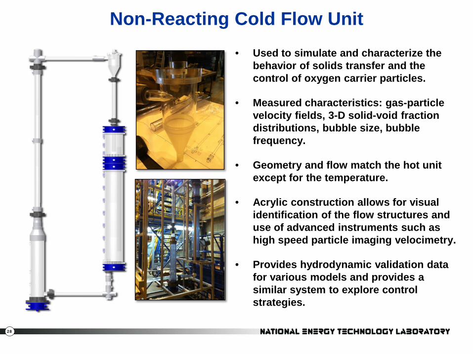
Non-Reacting Cold Flow Unit • Used to simulate and characterize the
behavior of solids transfer and the control of oxygen carrier particles.
• Measured characteristics: gas-particle velocity fields, 3-D solid-void fraction distributions, bubble size, bubble frequency.
• Geometry and flow match the hot unit except for the temperature.
• Acrylic construction allows for visual identification of the flow structures and use of advanced instruments such as high speed particle imaging velocimetry.
• Provides hydrodynamic validation data for various models and provides a similar system to explore control strategies.

29
Where and how can chemical looping work? Industrial applications (includes NG, smaller scale)
Power applications (coal, 100+MW scale)
Attributes: Fuel (NG, solid fuels) Size Cost Performance System issues & configuration Heat and material balances Attrition Material supply & handling Heat exchanger/integration Sensors and control Emissions Carrier cost/supply & re-use Components Hydrodynamics Heat transfer Size/cost Basic data Carrier capacity Carrier reaction rate w/oxygen Carrier reaction rate w/fuel Carrier degradation
Iterate with more information
ICMI work elements provide the data and analysis.
30
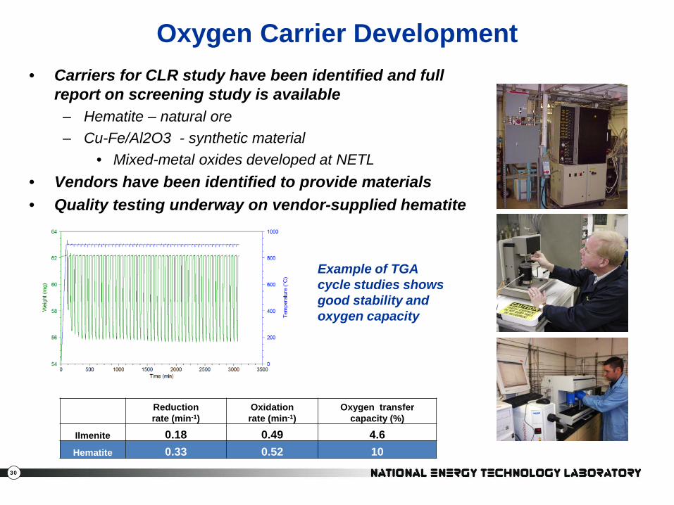
• Carriers for CLR study have been identified and full report on screening study is available
– Hematite – natural ore – Cu-Fe/Al2O3 - synthetic material
• Mixed-metal oxides developed at NETL • Vendors have been identified to provide materials • Quality testing underway on vendor-supplied hematite
Reduction rate (min-1)
Oxidation rate (min-1)
Oxygen transfer capacity (%)
Ilmenite 0.18 0.49 4.6 Hematite 0.33 0.52 10
Example of TGA cycle studies shows good stability and oxygen capacity
Oxygen Carrier Development

31
Attrition Unit Shakedown Using Alumina Powder
Boring is Better !
Attritted particles should show up here.

32
Summary
• Industrial Carbon Management Initiative : technologies and validated simulation tools for carbon capture and storage from industrial sources: – Chemical Looping (CL) as a capture technology – Depleted shale gas reservoirs for CO2 sequestration – Basic research in conversion of CO2 to useful chemicals using light or
waste heat • Research in progress covers
– Economic analysis of promising industrial CL applications – Development of oxygen carriers and reactor configurations – Validation of numeric models for detailed simulations & scale-up
• Commercial and research interest is welcome!

33
ICMI Reports (contact NETL)
– 2011 Annual Report on ICMI Project – Literature Survey of Kinetic Parameters Relevant to Chemical Looping Combustion – Chemical Looping Kinetic Rate Model – Literature Review of Attrition Testing – Literature Review of Solid-Solid Separation – Evaluation of Commercially Available Solids Flow Sensors and Technologies for Chemical
Looping Application – Oxygen Carrier Development for Chemical Looping Combustion with Natural Gas
Literature Review – The Development of Applicable Oxygen Carrier Materials for Chemical Looping
Combustion Using Methane as Fuel – Modeling Lifetime of Corrodible Components Literature Review – Hydrogen Production Screening Study – Ca-Sorbent Development for Carbon-neutral Industrial Gas Production of Hydrogen Using
Ca Looping – Design Basis for Storage of CO2 in Depleted Shale Gas Reservoirs – CFBC Furnace Temperature and Other Considerations