Industrial Battery Service Manual 0656A lead-acid motive power battery supplies direct current (DC)...
40
Transcript of Industrial Battery Service Manual 0656A lead-acid motive power battery supplies direct current (DC)...


2
PageINTRODUCTION ………………………………………………… 2
SECTION I - THEORY OF OPERATION/BATTERY CONSTRUCTION …………………… 4 Discharging/Recharging Characteristics…………………… 4 Battery Ratings ……………………………………………… 4 Battery Voltage ……………………………………………… 4 Ampere Hour (AH)…………………………………………… 5 Kilowatt Hours (KWH) ……………………………………… 5 Positive Plate Capacity ……………………………………… 5 Specific Gravity ……………………………………………… 5 Specific Gravity During Recharge ………………………… 5 Grid Casting ………………………………………………… 6 Apply Active Material………………………………………… 6 Curing and Drying …………………………………………… 6 Plate Formation ……………………………………………… 6 Wrapping Positive Plates …………………………………… 6 Assembling An Element …………………………………… 7 Finishing the Cell Assembly ………………………………… 7 Assembling into Trays ……………………………………… 8 Battery Finishing and Shipping……………………………… 8
SECTION II - BATTERY SAFETY ……………………………… 9 Hazardous Elements………………………………………… 9 Wearing Protective Clothing………………………………… 9 Lifting Batteries ……………………………………………… 9 Using the Battery as a Counterbalance …………………… 9
CHARGING BATTERIES Charging Areas — Proper Equipment …………………… 10 Charging Areas — Proper Ventilation …………………… 10 Connecting/Disconnecting Charger ……………………… 10 Sparks/Open Flames ……………………………………… 10
HANDLING ACID Pouring Acid ………………………………………………… 10 Mixing Electrolyte …………………………………………… 10 First Aid for Acid Splash …………………………………… 10 Eye Wash and Emergency Shower Facilities …………… 11 Neutralizing Acid and Electrolyte ………………………… 11 Repairing Batteries ………………………………………… 12 SECTION III - INSTALLATION AND USE …………………… 12 Receiving a Battery ………………………………………… 12 Temporary Storage ………………………………………… 12 Placing a Wet Charged Battery in Service ……………… 12 Placing a Dry Charged Battery in Service………………… 13 Cycling Characteristics……………………………………… 13
PageSECTION III - INSTALLATION AND USE (Cont.) Operation of the Battery …………………………………… 13 Specific Gravity and On-Charge Cell Voltage Temperature Correction……………………… 13 BATTERY CHARGING ………………………………………… 13 Basic Charging Facts ……………………………………… 13 Specific Gravity Temperature Correction ………………… 14 Charging Methods…………………………………………… 14 The Charging Process ……………………………………… 14 Improper Charging ………………………………………… 16 Charging Safety……………………………………………… 16
SECTION IV - BATTERY MAINTENANCE AND TROUBLE SHOOTING …………………………………… 16 Reading Hydrometers and Thermometers ……………… 17 Using a Voltmeter …………………………………………… 17 Battery Inspection…………………………………………… 17 Adding Water/Adjust Electrolyte Levels…………………… 18 Battery Cleaning Wash Unit ……………………………… 18 Performing a Test Discharge ……………………………… 19 Correcting a Sulfated Battery ……………………………… 19 Procedure for Adjusting the Specific Gravity of the Electrolyte of a Battery …………… 20 Storage Battery Troubleshooting Chart …………………… 21 Basic Rules for Battery Care and Maintenance ………… 23
SECTION V - VALVE REGULATED LEAD-ACID BATTERIES ……………………………………… 24 Operation of a Gel Cell……………………………………… 24 Charging a Gel Cell ………………………………………… 24 Operating Instructions ……………………………………… 25 Maintenance Instructions…………………………………… 26
SECTION VI - BATTERY REPAIR Repair or Replace…………………………………………… 27 Gas Purging ………………………………………………… 27 Removing Connectors ……………………………………… 27 Removing a Cell …………………………………………… 27 Removing an Element ……………………………………… 28 Reassembling the Battery ………………………………… 29 Attaching Intercell Connectors …………………………… 30 Replacing Acid and Charging ……………………………… 30
GLOSSARY OF BATTERY TERMINOLOGY …………… 31-35
Table of Contents
INTRODUCTION
Storage batteries do not store electrical energy, but convert elec-trical energy into chemical energy which is slowly accumulated asthe charge progresses. A battery in use is said to be on discharge.During discharge, the chemical energy stored in the battery is con-verted into usable electrical energy.A lead-acid motive power battery supplies direct current (DC)
power to electric lift trucks, tractors and pallet trucks. This type ofbattery consists of a metal tray containing cells, connected in series.These batteries come in a wide variety of shapes, sizes, voltagesand ampere-hour capacities.Each cell in a motive power battery contains positive and negative
plates. All of the positive plates are joined in parallel to the positivepost and strap, to form a positive group. The negative plates also arejoined in parallel to the negative post and strap to form a negativegroup. These groups are separated and insulated from one anotherand they are immersed in a solution of sulfuric acid and water, calledelectrolyte. These groups of plates, separators, posts and straps arecalled an element and it is contained in an acid-proof plastic jar.
The cutaway illustration (Fig. A-1) shows the construction of anEast Penn battery cell. Each positive plate consists of a lead-alloygrid structure which is filled with a paste of active material, madefrom lead oxide. The active material is forced into the positive gridstructure during manufacturing and is held firmly to the grid by a sys-tem of vertical and horizontal glass fiber mats, which reinforce andinsulate the positive plate. A retainer and bottom shield encase eachpositive plate and mat assembly to help prevent short circuits.The negative plate also consists of a lead alloy grid structure that
is filled with active material. But because negative plates undergomuch less active material shedding, no reinforcing glass fiber matsare needed. Separators provide insulation between the positive andnegative plates. The positive and negative plates are connected totheir respective posts by positive and negative straps.A more detailed description of battery construction appears in
Section I.
COVERHeat sealed with lead insert bushing prevents leakage and voltage-to-ground.
O-RING SEALAccomodates positive plate growth without cover distortion and leakage.
POSTSpecial alloy for increased strength and conductivity.
POST PLATE STRAPExtra heavy to ensure a permanent connection between posts and plates.
POSITIVE GRIDA non-porous lead alloy casting designed for maximum current carrying capacity, capable of many years of dependable service. Lead alloy is manufactured on-site and undergoes rigid testing before, during and after casting.
ACTIVE MATERIALManufactured on-site to exacting specifications and uniformly appliedunder rigid laboratory control to ensure maximum efficiency throughout long battery life.
JARMolded of high impact-resistant material to remain leak-free under the roughest conditions.
BRIDGEProvides firm element support and ample sediment space.
BOTTOM SHIELDProvides extra protection on bottom of positive plate to prevent shorting between plate and sediment.
VENT CAPQuarter-turn bayonet style simplifies watering and inspection.
SEPARATOR GUARDWhite color increases visibility for fast electrolytecheck. Solid insulating guardextends beneath the straps toprevent shorting between theplates and straps.
NEGATIVE PLATEEngineered to complement positive plate performance.
VERTICAL MATLaminated construction com-prised of uniformly spaced, fine glass tape that imbeds into the active material. Also features an inter-wovenglass fiber mat wrapped vertically around the positiveplate ensuring optimum activematerial retention.
HORIZONTAL MATMade of glass fibers with an insoluble binder. Breaks up gas bubbles and increases positive plate insulation and performance.
RETAINERA high porosity perforated envelope that encases positiveplates and glass mats to prevent shorts and ensure maximum performance and life.
SEPARATORImpervious to heat, acid andcorrosion, deep channeled,microporous separators provideinsulation between positive andnegative plates while allowingthe free flow of electrolytethroughout the cell.
ELECTROLYTEIn ample volume to ensure top performance at all rates of discharge.
STEEL TRAYHeavy gauge with acid-resistantprotective coating. Steel covers furnished as required.
Fig. A-1
Manufactured using the world’s most modern computer integrated manufacturing techniques…
3
SECTION I - THEORY OF OPERATION/BATTERY CONSTRUCTION OF LEAD ACID STORAGE BATTERIES
4
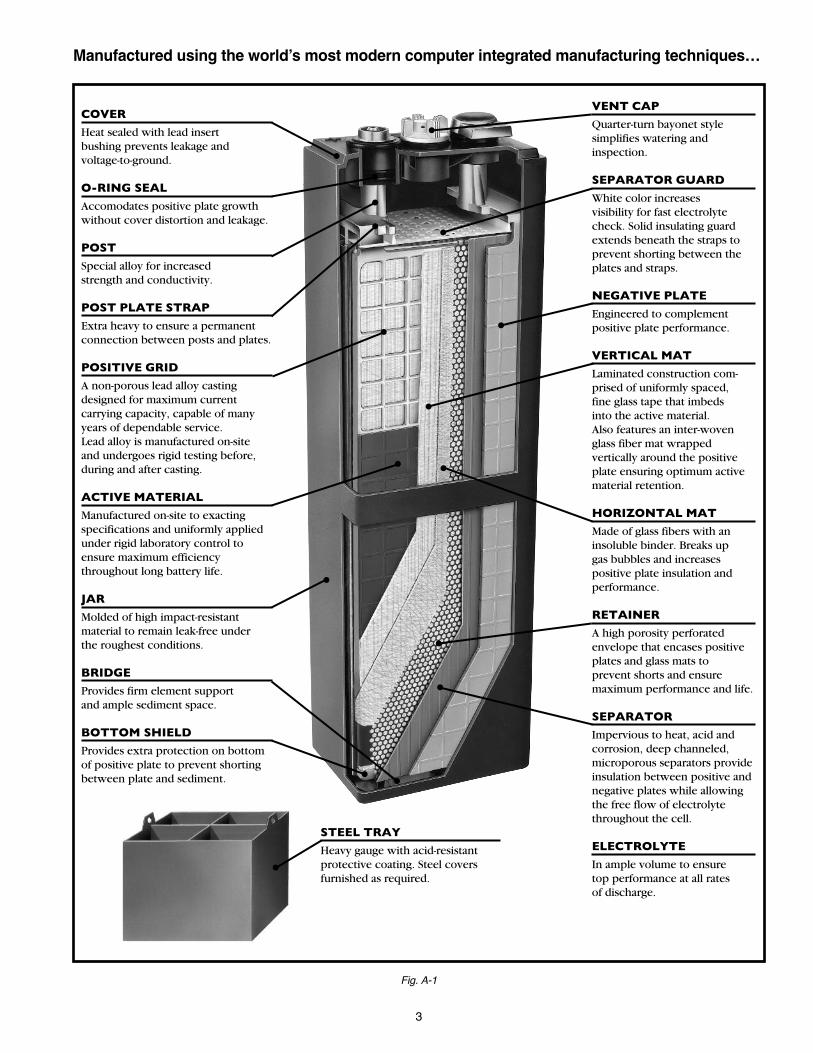
Theory of OperationDischarging/RechargingCharacteristicsIn a fully charged condition the active material in the positiveplate is lead peroxide (PbO2) and the active material in the neg-ative plates is sponge lead (Pb). The electrolyte has maximumsulfuric acid content and its temperature corrected specificgravity ranges should comply with the manufacturer’s recom-mended full charge specific gravity specifications (See Table 1-1 ). (See Table 3-1 - shown on page 14 - SpecificGravity Temperature Corrections).
Recommended Specific Gravity Battery Type Range @ 77°F/25°CStandard “D” Series 1.280 - 1.295Maintenance Saver “M” Series 1.245 - 1-255Max Powr “P” Series 1.320 - 1.330Diesel Starting “DL/DLU” Series 1.245 - 1.255Hydra Saver “H” Series 1.295 - 1.305
When fully charged, each cell has a voltage of approximatelytwo (2) volts on open circuit. However, a cell may have a volt-age from 2.12 to 2.70 volts while being charged. A celldevelops a voltage potential when two dissimilar metals areimmersed in a suitable electrolyte. The two metals used in lead-acid cells are lead peroxide (PbO2) and sponge lead (Pb), andthe electrolyte is dilute sulfuric acid (H2SO4). This combinationof dissimilar metals and electrolyte results in a voltage potentialof nominally two (2) volts per cell and their potential ability todeliver this voltage under varying load and for varying periodsof time.
When a battery is discharged, the internal components of eachcell undergo chemical changes (Figure I-1). During the dis-charge cycle, the composition of the positive plates changesfrom lead peroxide (PbO2) to lead sulfate (PbSO4) and the neg-ative plates from sponge lead (Pb) to lead sulfate (PbSO4) Thesulfate on both the positive and negative plates comes from thesulfuric acid in the electrolyte solution combining chemicallywith the active material of the plates. This chemical reactionreduces the sulfuric acid content in the electrolyte. The specificgravity of the electrolyte is reduced and approaches that ofwater (1.100). Cell voltage decreases during the dischargebecause the two (2) dissimilar metals (PbO2) and (Pb) arebecoming more similar (PbSO4).
During charging, the discharging reaction is reversed and thechemical energy is restored. The lead sulfate on the positiveplates converts back to lead peroxide (PbO2) and the lead sul-fate on the negative plates converts back to sponge lead (Pb).The released sulfate returns to the electrolyte solution, increas-ing the sulfuric acid content, which in turn increases the specificgravity. When these electrochemical reactions are complete,the cell is again fully charged.
During charging, hydrogen gas is formed on the negative platesand oxygen is formed on the positive plates. This explosive gasmixture is vented from the battery through the vent/filler caps. THE WARNINGS (SHOWN ON PAGE 5) APPLY TO ALLCELLS OR BATTERIES.
Battery RatingsA single lead-acid cell does not have sufficient power to handlemost requirements. However connecting a number of cellstogether in series results in a battery capable of supplying high-er power demands.
Battery VoltageThe number of cells is determined by the required nominaloperating voltage of the equipment. Since each cell has a nomi-nal voltage of two (2) volts, a 36 volt industrial truck will requirean 18-cell battery (18 cells x 2 volts/cell = 36 volts).
Fig. I-1
Table 1-1
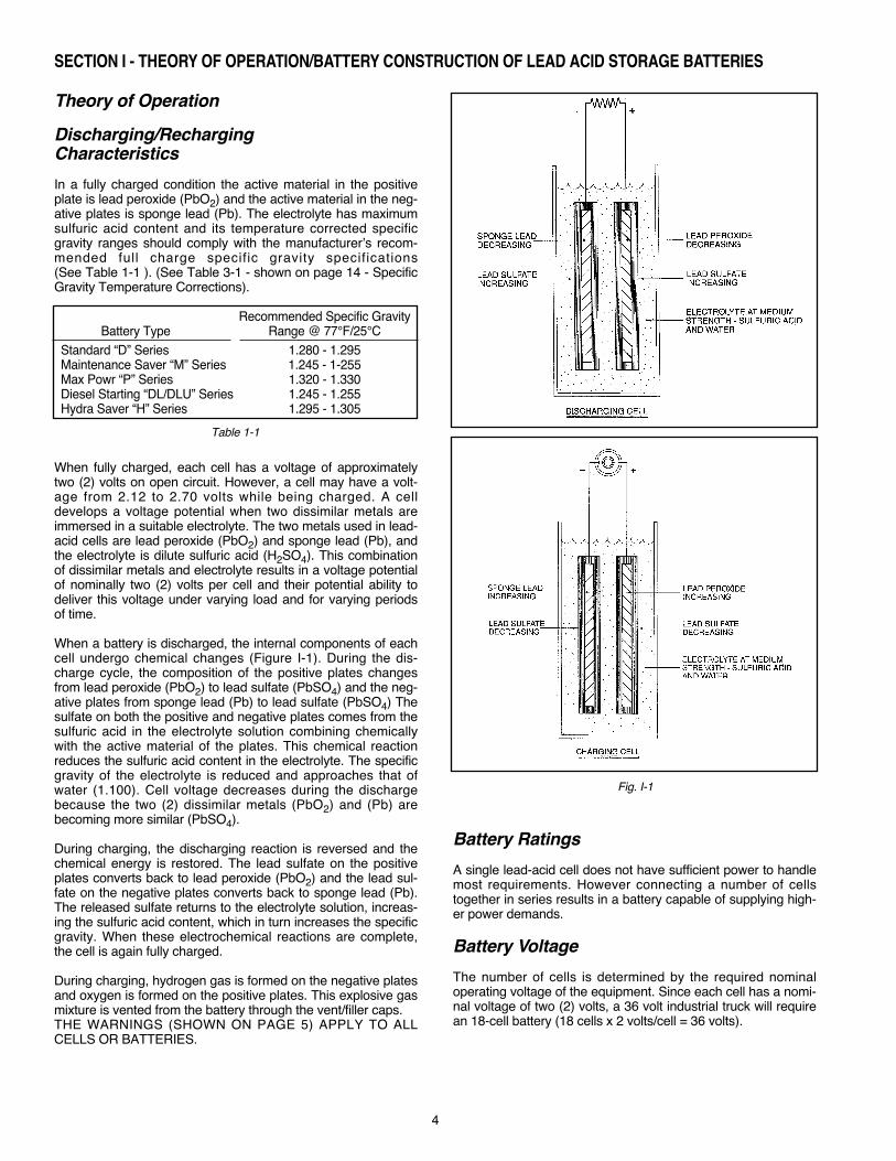
Danger
HYDROGEN GAS FROM THE BATTERY OR CELL CANEXPLODE. DO NOT SMOKE, USE AN OPEN FLAME, ORCREATE AN ARC OR SPARKS IN THE VICINITY OF INDI-VIDUAL CELLS OR BATTERIES. VENTILATE WELL WHENIN AN ENCLOSED SPACE AND WHEN CHARGING.
THIS BATTERY OR INDIVIDUAL CELL CONTAINS SULFU-RIC ACID WHICH CAUSES SEVERE BURNS. DO NOT GETIN EYES, ON SKIN OR ON CLOTHING. IN CASE OF CON-TACT, FLUSH IMMEDIATELY WITH CLEAN WATER.OBTAIN MEDICAL ATTENTION IF EYES ARE AFFECTED.
PERSONAL SAFETY EQUIPMENT IS RECOMMENDEDWHEN WORKING WITH BATTERIES AND SHOULD BEUSED IN ACCORDANCE WITH LOCAL REQUIREMENTS;SAFETY GLASSES, GOGGLES OR A FACE SHIELD.RUBBER OR PLASTIC GLOVES AND A RUBBER OR PLAS-TIC APRON ARE ITEMS OFTEN USED IN THIS TYPE OFWORK. EQUIPMENT WHICH WILL PROTECT THE EYESFROM ACID SPLASHES IS THE MOST IMPORTANT SINCETHE EYES CAN BE SERIOUSLY AFFECTED IN A VERYSHORT TIME.
Ampere Hour (AH)The electrical capability of a storage battery is usuallyexpressed in ampere-hours. The ampere-hour capacity is thenumber of ampere-hours which can be delivered under speci-fied conditions of temperature, rate of discharge, and finalvoltage. Basically, ampere-hours are determined by multiplyingthe number of amperes which the battery will deliver by thenumber of hours during which the current is flowing. Example:100 amperes x 6 hours to 1.70 volts per cell = 600 ampere-hours (six hour rate). The size and number of plates whichmake up the element then determine total cell or battery capaci-ty. Due to the variety of job requirements batteries areproduced with many different sizes of cells.
Kilowatt Hours (KWH)Battery capacity is also expressed in kilowatt-hours (KWH),which is the product of ampere x time x average volts per cellduring discharge. Example: 100 amps x 6 hours x 1.930 aver-age volts per cell = 1,158 watt hours ÷ 1000 = 1.158 KWH. Foran 18-cell battery, the capacity would be 1.158 x 18 = 20.84KWH. Increasing or decreasing the size of the cells or the num-ber of cells in the battery can vary the kilowatt-hour rating.
Positive Plate CapacityPositive plate capacity is the ampere delivery for a fixed periodof time (usually six hours) for a particular size positive plate. ADeka D100 type positive plate has the capability of delivering16.66 amperes for six hours or 100 ampere hours (16.66 x 6 =100 AH) to a final voltage of 1.70. Increasing or decreasing thenumber of positive plates in the cell can vary this ampere-hourrating or capacity. In the previous examples, the battery is an18-cell, D100-13 plate unit. To determine the number of positiveplates in each cell, subtract one from the total number of platesin the cell and divide by two. Example: 13 – 1 = 12 ÷ 2 = 6 posi-tive plates per cell; 6 positive plates x 100 ampere-hours each =600 AH. The use of a different type of positive plate, such as aD75 or D125, will respectively decrease or increase theampere-hour capacity. The above ratings are based on an elec-trolyte temperature of 77°F/25°C with a full charge specificgravity at battery nameplate rating.
Specific GravityThe term specific gravity describes the ratio of the density ofelectrolyte to the density of water. Electrolyte weighing 1.2times as much as the same volume of water has a specificgravity of 1.200. The full charge specific gravity of a cell is amatter of design and depends on several factors. The specificgravity must be high enough to contain the amount of sulfuricacid necessary to meet the chemical needs of a cell. If the sul-furic acid content is too high, damage may result to the cell.Since the acid content of the electrolyte decreases linearly asthe cell is discharged, the decrease in specific gravity is directlyproportionate to the amount of ampere-hours removed (refer toTable 3-2, page 15).
The specific gravity at any point in the discharge indicates thedepth of discharge and can be translated into ampere-hoursremoved. A cell having a full charge specific gravity of 1.290and a final specific gravity of 1.140 will have a specific gravitydrop of 150 points. Example: Assume the specific gravity is1.190 at the end of the discharge. That is 100 points specificgravity below the full charge gravity; therefore, = 67% dis-charged of rated capacity. Allow at least onehour after end of discharge for the electrolyte to diffuse andgive a true reading corrected to 77°F/25°C.
The linear relation of specific gravity to state of discharge canbe used in tests to determine power consumption or capacityrequired. Tests of this kind can be made to demonstrate that alift truck may require a larger capacity battery to do the job, andcan lead to the solution of a problem.
Specific Gravity During RechargeThe rise in specific gravity during recharge is not uniform orproportional to the amount charge returned in ampere-hours.During the early part of the charge, there is no gassing action tomix the electrolyte with the heavier acid being released from theplates. The heavier sulfuric acid will lay on the bottom. Ahydrometer reading which draws electrolyte from the top of thecell does not indicate the true specific gravity or actual state ofcharge. During the gassing portion of the charge, the sulfuricacid mixes, and the specific gravity rises rapidly to full chargevalue.
100150
SECTION I - THEORY OF OPERATION/BATTERY CONSTRUCTION OF LEAD ACID STORAGE BATTERIES (cont.)
5
Manufactured by: East Penn Manufacturing Co.102 Deka Road, Lyon Station, PA 19536 610-682-6361 USA
PROPOSITION 65 WARNING: Battery posts, terminals and related accessories contain lead and lead compounds, chemicals known to the State of California to cause cancer and reproductive harm. Batteries also contain other chemicals known to the State of California to cause cancer. WASH HANDS AFTER HANDLING.WARNING: Risk of fire, explosion or burns. Do not disassemble or incinerate. Not recommended for inverted use. Follow product charging instructions. High Voltage: Risk of shock. Do not touch uninsulated terminals or connectors. Keep Vent Caps Tightly in Place
Harmful if swallowed, inhaled, or in contact with skin.Acid causes severe skin burns and eye damage. May damage fertility or the unborn child if ingested or inhaled.May cause harm to breast-fed children.May cause cancer if ingested or inhaled.Causes skin irritation, serious eye damage. Contact with internal components may cause irritation or severe burns. Causes damage to central nervous system, blood and kidneys through prolonged or repeated exposure if ingested or inhaled.Irritating to eyes, respiratory system, and skin.May form explosive air/gas mixture during charging.Extremely flammable gas (hydrogen). Explosive, fire, blast or projection hazard.
Obtain special instructions before use.Do not handle until all safety precautions have been read and understood.Wash thoroughly after handling.Do not eat drink or smoke when using this product.Avoid contact during pregnancy/while nursing.Wear protective gloves/protective clothing, eye protection/face protection. Use only outdoors or in a well-ventilated area.Avoid contact with internal acid.Do not breathe dust/fume/gas/mist/vapors/spray.Keep away from heat/sparks/open flames/hot surfaces. No smoking.IF SWALLOWED OR CONSUMED: rinse mouth. Do NOT induce vomiting. Call a poison center/doctor if you feel unwell.
IF ON CLOTHING OR SKIN (or hair): Remove/Take off immediately all contaminated clothing and wash it before reuse. Rinse skin with water/shower. IF INHALED: Remove person to fresh air and keep comfortable for breathing. Immediately call a POISON CENTER or doctor/physician.IF IN EYES: Rinse cautiously with water for several minutes. Remove contact lenses, if present and easy to do. Continue rinsing. If exposed/concerned, or if you feel unwell seek medical attention/advice.Store locked up, in a well-ventilated area, in accordance with local and national regulation.Dispose of contents/container in accordance with local and national regulation.Keep out of reach of children.
Lead AcidBattery
Electrolyte(Sulfuric Acid)
DANGER Contains: Lead, Sulfuric Acid (Electrolyte), Lead Compounds.
See P.23 for full warranty information.
Battery Construction
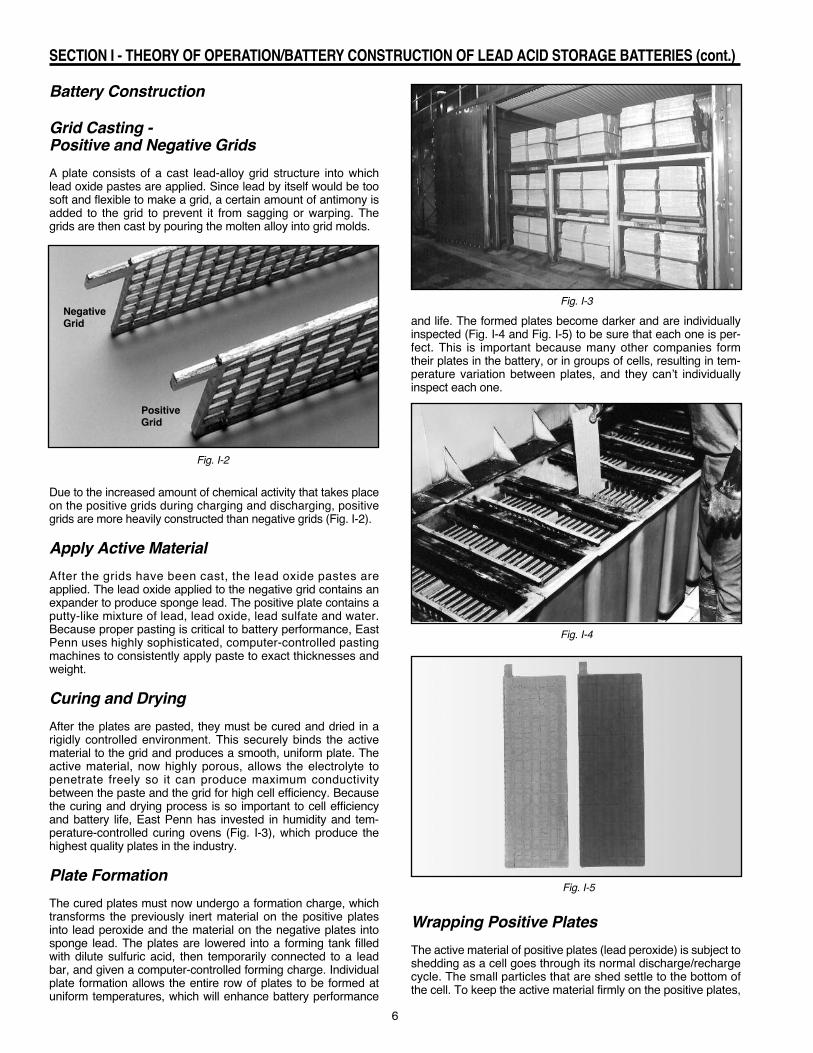
Grid Casting - Positive and Negative GridsA plate consists of a cast lead-alloy grid structure into whichlead oxide pastes are applied. Since lead by itself would be toosoft and flexible to make a grid, a certain amount of antimony isadded to the grid to prevent it from sagging or warping. Thegrids are then cast by pouring the molten alloy into grid molds.
Due to the increased amount of chemical activity that takes placeon the positive grids during charging and discharging, positivegrids are more heavily constructed than negative grids (Fig. I-2).
Apply Active MaterialAfter the grids have been cast, the lead oxide pastes areapplied. The lead oxide applied to the negative grid contains anexpander to produce sponge lead. The positive plate contains aputty-like mixture of lead, lead oxide, lead sulfate and water.Because proper pasting is critical to battery performance, EastPenn uses highly sophisticated, computer-controlled pastingmachines to consistently apply paste to exact thicknesses andweight.
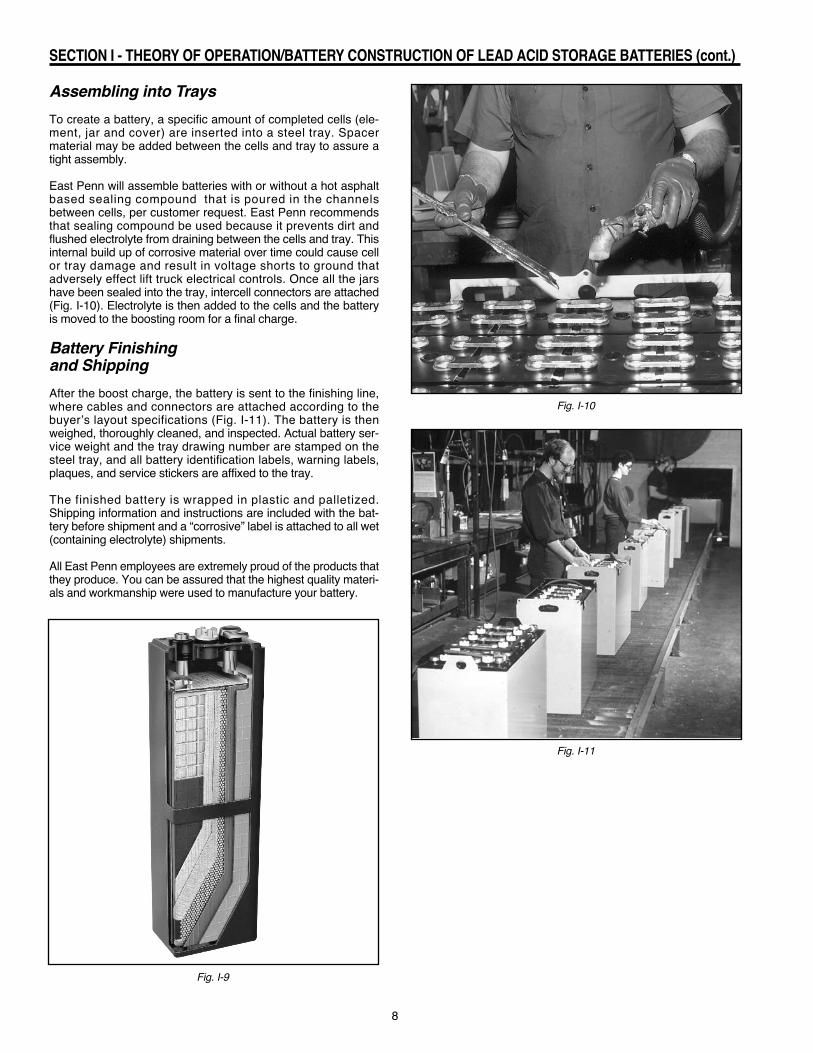
Curing and DryingAfter the plates are pasted, they must be cured and dried in arigidly controlled environment. This securely binds the activematerial to the grid and produces a smooth, uniform plate. Theactive material, now highly porous, allows the electrolyte topenetrate freely so it can produce maximum conductivitybetween the paste and the grid for high cell efficiency. Becausethe curing and drying process is so important to cell efficiencyand battery life, East Penn has invested in humidity and tem-perature-controlled curing ovens (Fig. I-3), which produce thehighest quality plates in the industry.
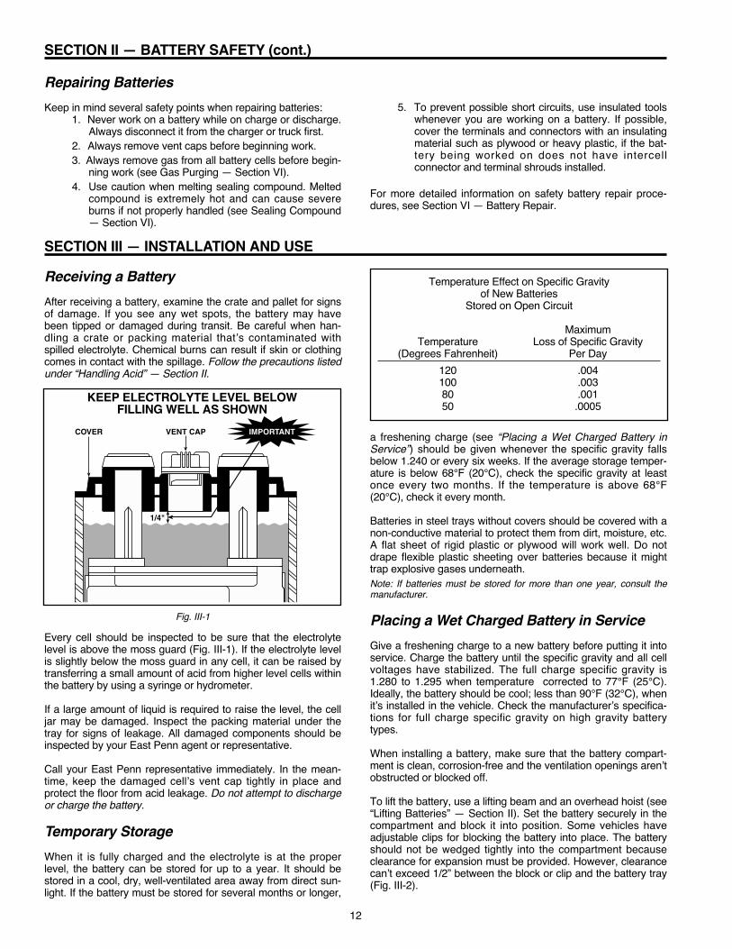
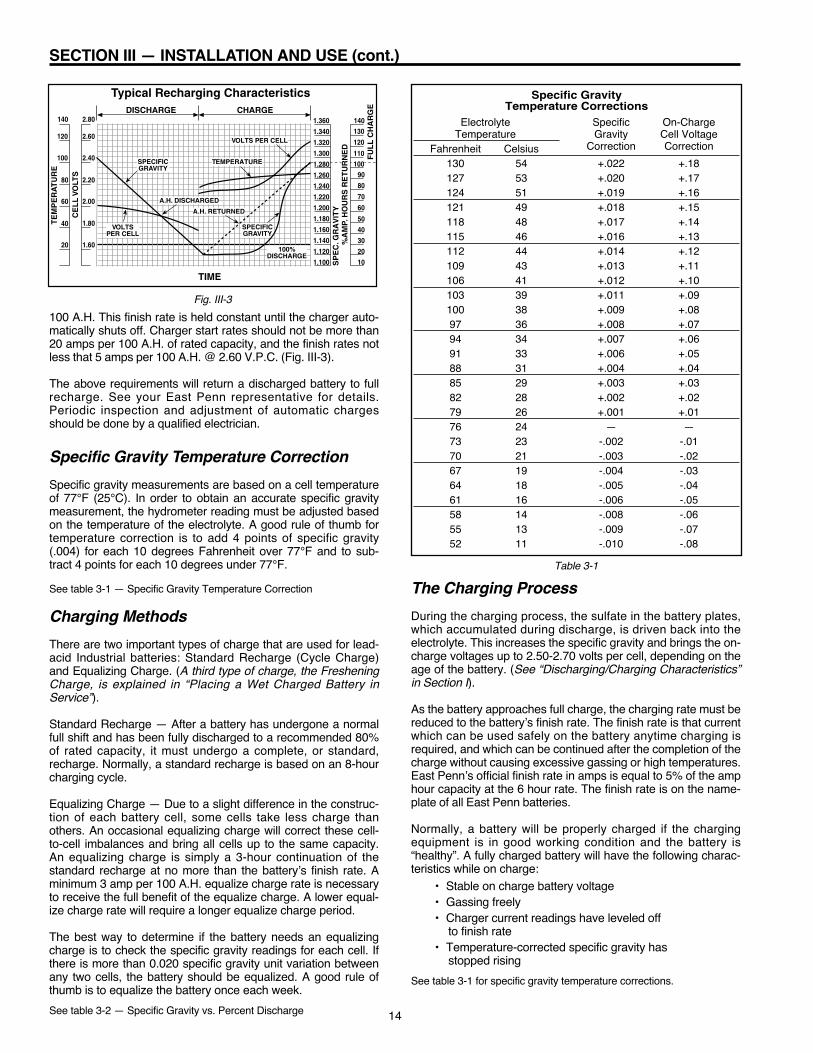
Plate FormationThe cured plates must now undergo a formation charge, whichtransforms the previously inert material on the positive platesinto lead peroxide and the material on the negative plates intosponge lead. The plates are lowered into a forming tank filledwith dilute sulfuric acid, then temporarily connected to a leadbar, and given a computer-controlled forming charge. Individualplate formation allows the entire row of plates to be formed atuniform temperatures, which will enhance battery performance
and life. The formed plates become darker and are individuallyinspected (Fig. I-4 and Fig. I-5) to be sure that each one is per-fect. This is important because many other companies formtheir plates in the battery, or in groups of cells, resulting in tem-perature variation between plates, and they can’t individuallyinspect each one.
Wrapping Positive PlatesThe active material of positive plates (lead peroxide) is subject toshedding as a cell goes through its normal discharge/rechargecycle. The small particles that are shed settle to the bottom ofthe cell. To keep the active material firmly on the positive plates,
6
SECTION I - THEORY OF OPERATION/BATTERY CONSTRUCTION OF LEAD ACID STORAGE BATTERIES (cont.)
Fig. I-2
Fig. I-3
Fig. I-4
Fig. I-5
PositiveGrid
NegativeGrid

they are “wrapped” with various retaining devices including glassfiber mats, fiberglass tape and a retainer/bottom shield (Fig. I-6).
The positive plates are first wrapped with a vertical mat, whichconsists of fiberglass tape and interwoven glass fibers. Theglass fibers imbed into the active material, strengthening in away similar to reinforcing rods in concrete. A horizontal glassfiber mat is then wrapped around the plate to break up any gasbubbles and increase the plate’s insulation. The wrapped plateis then encased in a perforated plastic retainer envelope thatfirmly holds the glass wraps in contact with the plate whileallowing the free flow of electrolyte to the plate. A bottom plateboot is added to prevent the sediment in the sediment chamberfrom contacting the bottom of the positive and negative platesand shorting out the cell.
Assembling An ElementA group of positive and a group of negative plates are stackedwith separators, inserted between each positive and negative
plate, to the desired cell size. Both outside plates are negative,therefore the number of plates per cell is always an odd num-ber, with each cell having one more negative then positiveplate.
The separators used to insulate the positive plate from the neg-ative plate are grooved on one side and flat on the other (Fig.I-7). The grooved side faces the positive plate. The flat sidefaces the negative plate because the sponge lead of the nega-tive plate would expand if it faced into the grooved side. Insome cases, positive plates can be inserted into separatorsleeves, which are two separators joined at the sides.
When assembling the stack of plates and separators into anelement, a post plate strap is welded onto the positive platelugs and another one is welded onto the negative plate lugs. Atthe same time, positive and negative posts are welded onto theproper plate straps. A perforated plastic moss shield is placedon top of the assembled plates (Fig. I-8). The moss shield alsoprotects the tops of the plates and separators and permits thegas bubbles to get up to the surface of the electrolyte.
Finishing the Cell AssemblyA finished cell consists of an element inserted into a high-impactplastic jar with a cover (Fig. I-9). Before the element goes intothe jar, a sediment bridge is installed to give the element firmsupport and provide a place for sediment to settle.
After the completed element is inserted into the jar, a highimpact plastic cover is placed on top and heat sealed onto thejar. The cover’s positive and negative terminals have a lead postbushing attached and are welded firmly to the element’s posts.
Each finished cell is air tested to ensure an air tight cover-to-jarand post-to-bushing seal. The air test can also detect any leaksin the high impact plastic jar.
7
SECTION I - THEORY OF OPERATION/BATTERY CONSTRUCTION OF LEAD ACID STORAGE BATTERIES (cont.)
Fig. I-6
Fig. I-8
Fig. I-7
Positive Plate Wrapped
8
Assembling into TraysTo create a battery, a specific amount of completed cells (ele-ment, jar and cover) are inserted into a steel tray. Spacermaterial may be added between the cells and tray to assure atight assembly.
East Penn will assemble batteries with or without a hot asphaltbased sealing compound that is poured in the channelsbetween cells, per customer request. East Penn recommendsthat sealing compound be used because it prevents dirt andflushed electrolyte from draining between the cells and tray. Thisinternal build up of corrosive material over time could cause cellor tray damage and result in voltage shorts to ground thatadversely effect lift truck electrical controls. Once all the jarshave been sealed into the tray, intercell connectors are attached(Fig. I-10). Electrolyte is then added to the cells and the batteryis moved to the boosting room for a final charge.
Battery Finishing and ShippingAfter the boost charge, the battery is sent to the finishing line,where cables and connectors are attached according to thebuyer’s layout specifications (Fig. I-11). The battery is thenweighed, thoroughly cleaned, and inspected. Actual battery ser-vice weight and the tray drawing number are stamped on thesteel tray, and all battery identification labels, warning labels,plaques, and service stickers are affixed to the tray.
The finished battery is wrapped in plastic and palletized.Shipping information and instructions are included with the bat-tery before shipment and a “corrosive” label is attached to all wet(containing electrolyte) shipments.
All East Penn employees are extremely proud of the products thatthey produce. You can be assured that the highest quality materi-als and workmanship were used to manufacture your battery.
SECTION I - THEORY OF OPERATION/BATTERY CONSTRUCTION OF LEAD ACID STORAGE BATTERIES (cont.)
Fig. I-9
Fig. I-10
Fig. I-11

9
Only trained and authorized personnel should change,repair or charge batteries.
Consult SDS for additional precautions and first aid measures. SDS sheets can be obtained atwww.eastpennmanufacturing.com
When used properly, a lead-acid motive power battery is a safe,dependable source of electrical power. However, if proper careand safety precautions aren’t exercised when handling a bat-tery, it can be an extremely dangerous piece of equipment.
There are four hazardous elements in a lead-acid battery: sulfu-ric acid, explosive gases, electricity, and weight.
Hazardous ElementsSulfuric Acid: The electrolyte in a lead-acid storage battery
is a diluted solution of sulfuric acid and water. Although the acidcontent in the solution is only about 37%, it’s still a strong corro-sive agent and can burn skin and eyes and eat holes in manytypes of fabric. (See Wearing Protective Clothing.)
Specific Gravity Reading % Acid Content by Weight 1.280 37.40 1.290 38.55 1.325 42.50
Explosive Gases: When a lead-acid battery is beingcharged, it produces an explosive mixture of hydrogen and oxy-gen gases. Make sure that all vent caps are unclogged andsecurely attached so that any gas is safely vented from the bat-tery. Never smoke, use an open flame or create an arc orsparks on or near a battery without first eliminating explosivegases from the cells you’re working on. (See Gas Purging —Section VI.)
Electricity: An electric shock hazard exists for persons whocontact live parts of batteries when the voltage is over 50 volts.The higher the voltage, the greater the electric shock hazard. Inaddition, metallic objects coming in contact with exposed cellconnectors will cause a short and can become very hot. Evenshorts involving a single cell can become hot enough to causesevere burns.
Weight: The average lift truck battery weighs more than2,000 pounds. Obviously it can cause serious injury if it isn’thandled carefully during installation, removal or transport. Useproper lifting equipment and techniques at all times.
Wearing Protective ClothingWhen working on or near batteries, always wear proper protec-tive clothes including a face shield, safety glasses, long-sleevedshirt, acid-resistant boots and gloves. Do not wear any metaljewelry because it can short circuit a battery and becomeextremely hot if it accidentally contacts exposed intercell con-nectors. Refer to detailed warnings, Section I, Page 5.
Lifting BatteriesChain hoists used to handle batteries should be equipped witha non-metallic container or bucket to prevent the chains fromdangling and possibly causing a short by coming in contact withexposed intercell connectors on the battery top. If no protectionis available, cover the battery with a non-conducting insulatingmaterial such as plywood or heavy plastic.
Always use the proper lifting equipment to reduce the risk oftray damage, shorting and possible injury. A wood insulatedbattery lifting beam used with an overhead hoist is the safestway to move a battery (Fig. II-1). An insulated lifting beam, withhooks that fit properly into the lifting ears in the tray, can beused with almost any type of overhead hoist. Be sure the liftinghooks align perfectly with the battery lifting ears. Misalignedhooks can cause battery lifting ear damage and could disen-gage while the battery is being lifted.
Using the Battery as a CounterbalanceIn order for most lift trucks to operate safely, the battery is used tocounterbalance the carried load. Therefore, a new or different bat-tery must fall within the recommended battery weight range. Thisbattery weight information is found on the nameplate of the truck. Abattery’s service weight is usually stamped on the tray near one ofthe lifting holes. A battery that’s too heavy or too light can changethe truck’s center of gravity and cause it to be unstable. It’s theuser’s responsibility to be sure that this weight is in the properrange.
SECTION II — BATTERY SAFETY
Fig. II-1
Manufactured by: East Penn Manufacturing Co.102 Deka Road, Lyon Station, PA 19536 610-682-6361 USA
PROPOSITION 65 WARNING: Battery posts, terminals and related accessories contain lead and lead compounds, chemicals known to the State of California to cause cancer and reproductive harm. Batteries also contain other chemicals known to the State of California to cause cancer. WASH HANDS AFTER HANDLING.WARNING: Risk of fire, explosion or burns. Do not disassemble or incinerate. Not recommended for inverted use. Follow product charging instructions. High Voltage: Risk of shock. Do not touch uninsulated terminals or connectors. Keep Vent Caps Tightly in Place
Harmful if swallowed, inhaled, or in contact with skin.Acid causes severe skin burns and eye damage. May damage fertility or the unborn child if ingested or inhaled.May cause harm to breast-fed children.May cause cancer if ingested or inhaled.Causes skin irritation, serious eye damage. Contact with internal components may cause irritation or severe burns. Causes damage to central nervous system, blood and kidneys through prolonged or repeated exposure if ingested or inhaled.Irritating to eyes, respiratory system, and skin.May form explosive air/gas mixture during charging.Extremely flammable gas (hydrogen). Explosive, fire, blast or projection hazard.
Obtain special instructions before use.Do not handle until all safety precautions have been read and understood.Wash thoroughly after handling.Do not eat drink or smoke when using this product.Avoid contact during pregnancy/while nursing.Wear protective gloves/protective clothing, eye protection/face protection. Use only outdoors or in a well-ventilated area.Avoid contact with internal acid.Do not breathe dust/fume/gas/mist/vapors/spray.Keep away from heat/sparks/open flames/hot surfaces. No smoking.IF SWALLOWED OR CONSUMED: rinse mouth. Do NOT induce vomiting. Call a poison center/doctor if you feel unwell.
IF ON CLOTHING OR SKIN (or hair): Remove/Take off immediately all contaminated clothing and wash it before reuse. Rinse skin with water/shower. IF INHALED: Remove person to fresh air and keep comfortable for breathing. Immediately call a POISON CENTER or doctor/physician.IF IN EYES: Rinse cautiously with water for several minutes. Remove contact lenses, if present and easy to do. Continue rinsing. If exposed/concerned, or if you feel unwell seek medical attention/advice.Store locked up, in a well-ventilated area, in accordance with local and national regulation.Dispose of contents/container in accordance with local and national regulation.Keep out of reach of children.
Lead AcidBattery
Electrolyte(Sulfuric Acid)
DANGER Contains: Lead, Sulfuric Acid (Electrolyte), Lead Compounds.
See P.23 for full warranty information.

CHARGING BATTERIES
Charging Areas — Proper EquipmentAll plants should have designated charging areas, especially if theychange batteries at the end of each shift.These areas should haveproper battery handling equipment including overhead hoists, liftingbeams, battery racks and cranes, and the area must be well venti-lated.
A source of running water nearby is desirable and a water hose atthe filling operation is recommended.
Racks used in the charging area must be insulated to prevent anysparking. The battery rack supports must also be suitably insulatedor made of non-conducting material.
The floors in battery and charging rooms should have an acid-resis-tant coating and be sloped toward a sump. They should always bewashed with clean water after an acid spill. The spill should be neu-tralized with a non-corrosive, water based neutralizing chemical thatis user safe and environmentally compliant.
Hand-operated fire extinguishes should be available in all chargingareas even if the areas are equipped with automatic sprinkler sys-tems. For information on extinguisher class, size and mountinglocations, consult local fire authorities or your insurance carrier.
Charging Areas — Proper VentilationThe charging area must be properly ventilated, either naturally orwith a ventilation system. When installing a ventilation system, anumber of factors must be considered, including the number andsize of batteries being charged at one time and the size, height andair-tightness of the room
Ventilation is considered satisfactory if the hydrogen concentrationdoesn’t exceed 2% in any one location. Concentrations of morethan 4% are explosive and dangerous. A number of instruments,such as combustible gas indicators and flammable vapor indica-tors, are available for continuous automatic analysis of hydrogencontent in the air.
Always keep tray covers and truck compartment covers open whencharging a battery. This helps cool the battery and disperse thegases.
Connecting/Disconnecting ChargerAlways turn the charger OFF before connecting or disconnecting abattery. Live leads can cause arcing and sparking, which couldcause an explosion if battery gases are present. In addition, the con-tact surfaces of the plugs or connectors will become pitted over time.
Sparks, Open FlamesBecause of the explosive gas mixtures generated while chargingbatteries, anything that could ignite the gas, such as sparks,open flames, an electrical arc, smoking, etc., must be prohibitedin the charging areas. To serve as a prominent reminder, “NO SMOKING” signs should be posted in all charging areas.
HANDLING ACID
Pouring AcidUse a carboy tinter or safety siphon when removing acid from acarboy container. The venting device in a carboy prevents splash-ing. Carboys should be stored in a cool place away from directsunlight. (Note: Use proper eye protection, protective clothing andequipment.)
Mixing ElectrolyteMix electrolyte in a heat and acid-resistant container. Always pouracid into water. Never pour water into acid because a violent chem-ical reaction can occur. Pour the acid slowly and stir the mixture sothe acid doesn’t settle on the bottom.
When using high specific gravity acid (above 1.400), take specialprecautions because it can be extremely dangerous. (Note: Useproper eye protection, protective clothing and equipment.)
Store acid and electrolyte solutions in covered containers made oflead, glass or acid-resistant plastic. Keep the containers in a cool,dry area away from direct sunlight.
Important - only the most experienced battery techniciansshould be allowed access to sulfuric acid and allowed to addacid for cell equalization purposes.
First Aid for Acid SplashEyes: Flush immediately with gently running water for at least
15 minutes, then see a doctor as quickly as possible. For contactlens wearers, remove the lens before the eyes are flushed. Abuffering or neutralizing agent shouldn’t be used in the eyes with-out the approval of medical or safety personnel.
Skin: Wash affected area under running water and apply achemical burn treatment. Severe burns require immediate medicalattention.
Clothing: If large areas of clothing have been splashed orsoaked, the clothing must be removed and the acid must be neu-tralized with a non-corrosive, water based neutralizing chemicalthat is user safe and environmentally compliant and then rinsedunder running water. If the clothing is rinsed quickly enough, thechances of damage to the material are lessened.
Acid-resistant boots should always be checked before wearing tobe sure that there are no acid puddles inside.
10
SECTION II — BATTERY SAFETY (cont.)

Eye Wash and Emergency Shower FacilitiesEmergency eye wash and acid neutralization facilities shouldbe located in the immediate work area for easy access. Thethree most popular types of eye wash and acid neutralizingequipment are the chemical burn station, deluge shower, andeye wash fountain.
1. A chemical burn station (Fig. II-2) is used in smaller bat-tery charging and repair areas. The station consists of awall-mounted plastic squeeze bottle that contains a buffer-ing solution for treating acid burns on skin, eyes andclothing. This inexpensive equipment should be used onlywhere acid with a specific gravity lower than 1.400 is used.A buffering or neutralizing agent shouldn’t be used in theeyes without the approval of medical or safety personnel.
2. A deluge shower (Fig. II-3) should be used where high spe-cific gravity acid (above 1.400) is handled. The shower usesa handle or foot treadle to turn on a powerful water streamthat can wash acid from skin and clothes.
3. An eye wash fountain (Fig. II-4) should be used whereverbatteries and/or acid is handled, regardless of the acid’sspecific gravity. This device produces two streams of waterso that both eyes can be flushed simultaneously.
Neutralizing Acid and ElectrolyteFor cleaning batteries, non-corrosive, water based batterycleaning products are all that should be used. For user safetyand environmental regulatory compliance, the cleaning liquidshould contain no hazardous chemical ingredients. Even someproducts labeled “Battery Cleaner” must be avoided because ofhazardous ingredients and damage to batteries and relatedequipment.
Acid spills are common in battery rooms. When acid spills occurit is critical to minimize:
1. Health and safety risk to personnel and the environment.
2. Damage to batteries, equipment, and surrounding surfaces.
3. Time to neutralize, absorb, and clean-up.4. Disposal costs of waste materials.5. Regulatory compliance risks and fines.
Neutralizing acid absorbers and spill kits have the performanceattributes required when dealing with acid spills. The ph neutraldry and non-hazardous waste is easy to sweep-up and disposeas non-hazardous waste.
11
SECTION II — BATTERY SAFETY (cont.)
Fig. II-2
Fig. II-3
Fig. II-4
Repairing BatteriesKeep in mind several safety points when repairing batteries:
1. Never work on a battery while on charge or discharge.Always disconnect it from the charger or truck first.
2. Always remove vent caps before beginning work.3. Always remove gas from all battery cells before begin-ning work (see Gas Purging — Section VI).
4. Use caution when melting sealing compound. Meltedcompound is extremely hot and can cause severeburns if not properly handled (see Sealing Compound— Section VI).
5. To prevent possible short circuits, use insulated toolswhenever you are working on a battery. If possible,cover the terminals and connectors with an insulatingmaterial such as plywood or heavy plastic, if the bat-tery being worked on does not have intercellconnector and terminal shrouds installed.
For more detailed information on safety battery repair proce-dures, see Section VI — Battery Repair.
Receiving a BatteryAfter receiving a battery, examine the crate and pallet for signsof damage. If you see any wet spots, the battery may havebeen tipped or damaged during transit. Be careful when han-dling a crate or packing material that’s contaminated withspilled electrolyte. Chemical burns can result if skin or clothingcomes in contact with the spillage. Follow the precautions listedunder “Handling Acid” — Section II.
Every cell should be inspected to be sure that the electrolytelevel is above the moss guard (Fig. III-1). If the electrolyte levelis slightly below the moss guard in any cell, it can be raised bytransferring a small amount of acid from higher level cells withinthe battery by using a syringe or hydrometer.
If a large amount of liquid is required to raise the level, the celljar may be damaged. Inspect the packing material under thetray for signs of leakage. All damaged components should beinspected by your East Penn agent or representative.
Call your East Penn representative immediately. In the mean-time, keep the damaged cell’s vent cap tightly in place andprotect the floor from acid leakage. Do not attempt to dischargeor charge the battery.
Temporary StorageWhen it is fully charged and the electrolyte is at the properlevel, the battery can be stored for up to a year. It should bestored in a cool, dry, well-ventilated area away from direct sun-light. If the battery must be stored for several months or longer,
a freshening charge (see “Placing a Wet Charged Battery inService”) should be given whenever the specific gravity fallsbelow 1.240 or every six weeks. If the average storage temper-ature is below 68°F (20°C), check the specific gravity at leastonce every two months. If the temperature is above 68°F(20°C), check it every month.
Batteries in steel trays without covers should be covered with anon-conductive material to protect them from dirt, moisture, etc.A flat sheet of rigid plastic or plywood will work well. Do notdrape flexible plastic sheeting over batteries because it mighttrap explosive gases underneath.Note: If batteries must be stored for more than one year, consult themanufacturer.
Placing a Wet Charged Battery in ServiceGive a freshening charge to a new battery before putting it intoservice. Charge the battery until the specific gravity and all cellvoltages have stabilized. The full charge specific gravity is1.280 to 1.295 when temperature corrected to 77°F (25°C).Ideally, the battery should be cool; less than 90°F (32°C), whenit’s installed in the vehicle. Check the manufacturer’s specifica-tions for full charge specific gravity on high gravity batterytypes.
When installing a battery, make sure that the battery compart-ment is clean, corrosion-free and the ventilation openings aren’tobstructed or blocked off.
To lift the battery, use a lifting beam and an overhead hoist (see“Lifting Batteries” — Section II). Set the battery securely in thecompartment and block it into position. Some vehicles haveadjustable clips for blocking the battery into place. The batteryshould not be wedged tightly into the compartment becauseclearance for expansion must be provided. However, clearancecan’t exceed 1/2” between the block or clip and the battery tray(Fig. III-2).
12
SECTION II — BATTERY SAFETY (cont.)
SECTION III — INSTALLATION AND USE
Temperature Effect on Specific Gravity of New Batteries
Stored on Open Circuit
Maximum Temperature Loss of Specific Gravity (Degrees Fahrenheit) Per Day 120 .004 100 .003 80 .001 50 .0005
1/4"
COVER VENT CAP IMPORTANT
Fig. III-1
KEEP ELECTROLYTE LEVEL BELOW FILLING WELL AS SHOWN

13
Be sure all vent caps are in place because electrolyte fromuncapped cells can corrode the tray and vehicle.
Placing a Dry Charged Battery in ServiceNote: The activation of dry charged batteries is an involved pro-cess which should be handled by trained personnel. For athorough explanation, refer to East Penn’s “Procedure forActivating Dry Charged Industrial Cells and Batteries,” which issupplied with every dry charge battery.
A dry charged battery is a fully charged battery from which allthe electrolyte has been removed. Because it’s essential tokeep these batteries in the dry state until ready for use, theyshould be stored in a cool, dry, low-humidity area with their ventcaps and protector cap and plugs tightly in place until ready foruse. When reactivated, install as described in “Placing a WetCharged Battery in Service.”
Cycling CharacteristicsEvery time a battery is discharged and then recharged it’scalled a cycle. An average battery lasts 1,500 to 1,800 cycles,or 5 to 6 years. (Actual battery life depends on battery type, theseverity of use, and how the battery was maintained while inservice.)
As a battery discharges, the voltage normally drops slowly atfirst and then more rapidly toward the end of the discharge.Battery temperature, on the other hand, rises during discharge,although the increase isn’t as high as it is during charging. Theamount of temperature increase depends on ambient tempera-ture, ampere discharge rate, and the amount of heat dissipation(which varies according to battery type).
To obtain maximum service life, batteries should be operated at115°F (46°C) or lower, and they shouldn’t be discharged tobelow 80% of rated capacity. Frequent over-discharging candrastically shorten battery life.
One way to prevent over-discharging is to be sure that theampere-hour (A.H.) capacity rating of the battery is high enoughfor the battery’s work load. The battery will over-discharge if itsworkload exceeds its capacity. For heavy-duty applications, ahigher capacity battery — such as East Penn’s MAX POWRbattery — may solve frequent over-discharge problems. Todetermine if a higher capacity battery is right for your needs,contact your East Penn agent or representative.
Operation of the BatteryThere are several factors that effect the operation of the batteryconcerning its ability to deliver capacity and life expectancy.Many chemical reactions are effected by temperature, and thisis true of the reaction that occurs in a storage battery. Thechemical reaction of a lead-acid battery is slowed down by alowering of the electrolyte temperature that results in lesscapacity. A battery that will deliver 100% of rated capacity at 77°F will only deliver 65% of rated capacity at 32°F. See Table 3-1,for specific gravity and on charge cell voltage temperature cor-rection.
Specific Gravity and On-Charge Cell VoltageTemperature CorrectionEXCESSIVE HEAT will contribute greatly to reducing batterylife by corroding the positive grids and excessive gassing whichloosens active material in the plates, especially the positiveplate. Over charging is the most common contributing factor toexcessive temperatures and gassing in a battery. A properlyrated and matched charger will help to avoid the problem ofovercharging.
CONSISTENT UNDERCHARGING of a battery will graduallyrun down the cells and result in one or more cells becomingcompletely discharged before the others, and may becomereversed. Capacity and life expectancy are greatly reduced byundercharging. Equalizing charges to return the cells to a nor-mal condition should be part of a weekly maintenance schedule.
OVERDISCHARGING can also cause permanent damage tothe battery. Recharging is more difficult and more time consum-ing. Often complete recharge is not attained and theundercharged battery is placed into service. Consequently, it isover discharged to a lower limit resulting in loss of capacity andpremature battery failure. Optimum battery life can be aided bylimiting the depth of discharge to 80% of its rated capacity.
A good battery maintenance program is necessary to protectlife expectancy and capacity of the battery. A more detailed dis-cussion of battery maintenance can be found in Section IV ofthis manual.
BATTERY CHARGING
Basic Charging FactsProper charging is essential for maximum battery life. In gener-al, the proper charging rate for lead-acid batteries is any ratewhich doesn’t produce temperature higher than 115°F (46°C),and any rate which doesn’t cause excessive gassing.
When a discharged battery is initially placed on charge, it drawsa current equal or close to the charger’s maximum output. Asthe battery’s voltage rises, the charger output should adjust tothe changing voltage to assure a safe, efficient charging rateduring all stages of the charge.
With today’s automatic start/stop charges, under and overcharg-ing are virtually eliminated. These “smart” charges havecomputerized control units that can determine when a battery isfully charged and then automatically terminate the charge cycle.For example: The charger delivers a “maximum” start rate of 20amps per 100 A.H. of rated capacity. As the voltage rises to 2.37volts @ 77°F (25°C) per cell, the gassing voltage of the battery isheld constant until the charge rate tapers down to 5 amps per
SECTION III — INSTALLATION AND USE (cont.)
Fig. III-2
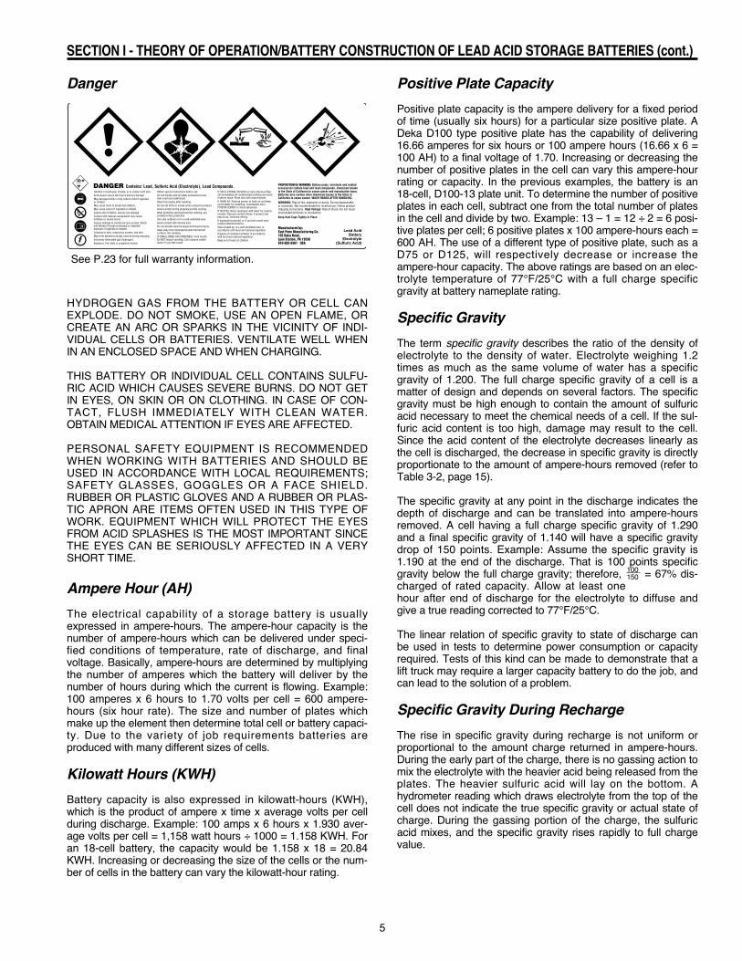
100 A.H. This finish rate is held constant until the charger auto-matically shuts off. Charger start rates should not be more than20 amps per 100 A.H. of rated capacity, and the finish rates notless that 5 amps per 100 A.H. @ 2.60 V.P.C. (Fig. III-3).
The above requirements will return a discharged battery to fullrecharge. See your East Penn representative for details.Periodic inspection and adjustment of automatic chargesshould be done by a qualified electrician.
Specific Gravity Temperature CorrectionSpecific gravity measurements are based on a cell temperatureof 77°F (25°C). In order to obtain an accurate specific gravitymeasurement, the hydrometer reading must be adjusted basedon the temperature of the electrolyte. A good rule of thumb fortemperature correction is to add 4 points of specific gravity(.004) for each 10 degrees Fahrenheit over 77°F and to sub-tract 4 points for each 10 degrees under 77°F.See table 3-1 — Specific Gravity Temperature Correction
Charging MethodsThere are two important types of charge that are used for lead-acid Industrial batteries: Standard Recharge (Cycle Charge)and Equalizing Charge. (A third type of charge, the FresheningCharge, is explained in “Placing a Wet Charged Battery inService”).
Standard Recharge — After a battery has undergone a normalfull shift and has been fully discharged to a recommended 80%of rated capacity, it must undergo a complete, or standard,recharge. Normally, a standard recharge is based on an 8-hourcharging cycle.
Equalizing Charge — Due to a slight difference in the construc-tion of each battery cell, some cells take less charge thanothers. An occasional equalizing charge will correct these cell-to-cell imbalances and bring all cells up to the same capacity.An equalizing charge is simply a 3-hour continuation of thestandard recharge at no more than the battery’s finish rate. Aminimum 3 amp per 100 A.H. equalize charge rate is necessaryto receive the full benefit of the equalize charge. A lower equal-ize charge rate will require a longer equalize charge period.
The best way to determine if the battery needs an equalizingcharge is to check the specific gravity readings for each cell. Ifthere is more than 0.020 specific gravity unit variation betweenany two cells, the battery should be equalized. A good rule ofthumb is to equalize the battery once each week.See table 3-2 — Specific Gravity vs. Percent Discharge
The Charging ProcessDuring the charging process, the sulfate in the battery plates,which accumulated during discharge, is driven back into theelectrolyte. This increases the specific gravity and brings the on-charge voltages up to 2.50-2.70 volts per cell, depending on theage of the battery. (See “Discharging/Charging Characteristics”in Section I).
As the battery approaches full charge, the charging rate must bereduced to the battery’s finish rate. The finish rate is that currentwhich can be used safely on the battery anytime charging isrequired, and which can be continued after the completion of thecharge without causing excessive gassing or high temperatures.East Penn’s official finish rate in amps is equal to 5% of the amphour capacity at the 6 hour rate. The finish rate is on the name-plate of all East Penn batteries.
Normally, a battery will be properly charged if the chargingequipment is in good working condition and the battery is“healthy”. A fully charged battery will have the following charac-teristics while on charge:
• Stable on charge battery voltage• Gassing freely• Charger current readings have leveled offto finish rate
• Temperature-corrected specific gravity hasstopped rising
See table 3-1 for specific gravity temperature corrections.
14
SECTION III — INSTALLATION AND USE (cont.)
Typical Recharging Characteristics
TE
MP
ER
AT
UR
E
CE
LL
VO
LTS
2.80
2.60
2.40
2.20
2.00
1.80
1.60
140
120
100
80
60
40
20 %A
MP.
HO
UR
S R
ET
UR
NE
D
140
120
100
80
60
40
20
TIME
10
30
50
70
90
110
130
FU
LL
CH
AR
GEDISCHARGE CHARGE
SP
EC
. GR
AV
ITY
1.360
1.340
1.320
1.300
1.260
1.240
1.220
1.200
1.180
1.160
1.140
1.120
1.100
1.280SPECIFICGRAVITY
VOLTSPER CELL
A.H. DISCHARGED
A.H. RETURNED
TEMPERATURE
100%DISCHARGE
SPECIFICGRAVITY
VOLTS PER CELL
Fig. III-3
Specific Gravity Temperature Corrections
Electrolyte Specific On-Charge Temperature Gravity Cell Voltage Fahrenheit Celsius Correction Correction 130 54 +.022 +.18 127 53 +.020 +.17 124 51 +.019 +.16 121 49 +.018 +.15 118 48 +.017 +.14 115 46 +.016 +.13 112 44 +.014 +.12 109 43 +.013 +.11 106 41 +.012 +.10 103 39 +.011 +.09 100 38 +.009 +.08 97 36 +.008 +.07 94 34 +.007 +.06 91 33 +.006 +.05 88 31 +.004 +.04 85 29 +.003 +.03 82 28 +.002 +.02 79 26 +.001 +.01 76 24 — — 73 23 -.002 -.01 70 21 -.003 -.02 67 19 -.004 -.03 64 18 -.005 -.04 61 16 -.006 -.05 58 14 -.008 -.06 55 13 -.009 -.07 52 11 -.010 -.08
Table 3-1

15
SECTION III — INSTALLATION AND USE (cont.)
ELECTROLYTE SPECIFIC GRAVITYVS. PERCENT DISCHARGE
GRAVITY
PERCENT DISCHARGED
0 20 40 60 80 100
1.100
1.120
1.130
1.140
1.150
1.160
1.170
1.180
1.200
1.220
1.240
1.250
1.260
1.270
1.280
1.290
1.300
D45 - D55D35 - D65D75 - D150H80
H120D110M75D160D85 - D100M85
D125
ELECTROLYTE SPECIFIC GRAVITYVS. PERCENT DISCHARGEGRAVITY
PERCENT DISCHARGED0 20 40 60 80 100
1.100
1.120
1.130
1.140
1.150
1.160
1.170
1.180
1.200
1.220
1.240
1.250
1.260
1.270
1.280
1.290
1.300
P49 - P60P38 - P22P82 - P165
P121
P170
1.310
1.320
1.325
P95 - P110
P140
Table 3-2
D and M Series MAX POWR Series

Proper maintenance is essential to obtain long life and maxi-mum efficiency from any Industrial battery. Carefully following ascheduled maintenance routine will help increase battery per-formance and prolong service life.
One of the keys to an effective battery maintenance program isto maintain an accurate records system of battery cycles andmaintenance/repair work for each battery. A records system isparticularly important for operations that use a large number ofbatteries.
If you don’t already have one, these procedures should helpyou create a reliable records system:
1. Assign a code/identification number to each battery andcharger. Use a multiple digit-system if you have severaldifferent sizes or types of batteries. Prefixes or suffixescan be used to identify batteries by size, voltage, shift,lift truck, etc.
2. Designate a “pilot cell” for each battery. Record the spe-cific gravity, voltage and temperature of the pilot cellwhen the battery is first received and equalized, andbefore and after each charge. The readings taken onthe pilot cell are considered to represent the specificgravity, voltage and temperature of all the cells. Always
use the same cell for the pilot cell. The pilot cellshould be positioned near the center of the battery andcan be identified with a marking of some sort on theintercell connector shroud or cell cover.
3. At least once each month, measure and compare thespecific gravity of all the cells. The readings should beuniform from cell to cell. If the specific gravity readingsfall 20 points (0.20) below the nominal specific gravityreading of 1.290, the electrolyte levels should bechecked and brought up to a uniform level before check-ing for a second time. If, at any time, the readings are 20points (.020) greater than the nominal specific gravityreadings of 1.290, or the range of the on-charge cellvoltage readings is more than 0.15 volts, the batterycould be showing signs of cell failure. Contact yourauthorized Deka Service Representative.
4. Remember to accurately record the number of cycles,specific gravity, temperature and voltage readings; andall maintenance and repair information for every battery.THE DAILY BATTERY RECORD (Fig. IV-1) is an exam-ple of a basic record-keeping form. You should use aform that best fits your operation’s individual needs. It isalso recommended that the identification number of thecharger used to charge the battery be recorded.
SECTION IV — BATTERY MAINTENANCE AND TROUBLESHOOTING
Improper ChargingImproper charging reduces battery capacity and life.Undercharging can cause residual sulfation to remain on plates,reducing cell performance. Sulfation also slowly occurs whenbatteries are stored for months without receiving periodic fresh-ening charges. The cells of a sulfated battery give low specificgravity and voltage readings. It’s difficult to bring a heavily sul-fated battery back to full charge and doing so will develop hightemperatures. (See “Correction of Sulfated Cells” — Section IV).Undercharging also results in insufficient gassing, which createsa high acid content at the bottom of the cell, eventually leadingto sulfation on the bottom part of the negative plates. This condi-tion can be corrected by periodic equalizing charges.Although all batteries are overcharged to an extent during everycharge cycle, severe overcharging results in excessive gassingand very high battery temperatures — both of which are damag-ing to the battery. Battery temperatures should not exceed115°F (25°C) during charging.Excessive gassing occurs when a high charging rate is contin-ued after the battery has been brought to its gassing voltage(2.37 volts per cell nominal). A noticeable bubbling of electrolytecan be seen, accompanied by high electrolyte temperature.Because the gas is released from the electrolysis of water,excessive gassing results in unusually high water usage. (Seethe Troubleshooting Chart at the end of Section IV for additionalcauses and remedies.)For reduced maintenance and long, trouble-free battery life,make sure all your batteries are properly charged. If you’re hav-ing trouble correcting any problems, contact your East Pennagent or representative.
Charging SafetyThere are several important safety precautions that should betaken when charging a battery:
• Do not use open flames when checking the electrolytelevels in storage batteries.
• Keep all open flames, sparks and matches away fromthe charging area. DO NOT SMOKE around the chargingarea.
• Only properly trained personnel should charge batteries.• Before a battery is removed from a truck, or charged in atruck, the truck’s electrical circuit should be open, thebattery should be unplugged from the truck, and thewheels should be chocked. (If removing the battery fromthe truck, be sure to use proper lifting methods andequipment.)
• The charger should be OFF before connecting it to thebattery.
• All mechanical connections on the battery and chargershould be tight. Loose connections can overheat andcause arcing that could cause a gassing cell to explode,or cables to become hot to the touch.
• Covers on battery trays should be kept open whilecharging to promote cooling and allow gas to escape. Ifthe battery remains in the truck during charging, keepthe battery compartment cover and battery tray coveropen.
• Vent plugs should be kept firmly in place at all times tominimize electrolyte spray when the battery gasses.
• The charger should be OFF before disconnecting thebattery.
• The charger connector shall not be plugged into the lifttruck connector under any circumstances.
16
SECTION III — INSTALLATION AND USE (cont.)

17
In addition to providing records of tests, repairs and individualperformance for each battery, accurate record keeping can alsoreveal other helpful information:
• Specific gravity records taken at the beginning andend of each cycle can pinpoint any irregularities in thebattery’s condition or in its operation. Readings takenbefore recharging can indicate possible over-discharg-ing and use in a low voltage condition, which eventuallycan cause damage to lift truck electrical componentsand shorten battery life.
• Maintenance and repair records can also point to bat-tery abuse as well as help gauge individual batteryperformance.
• Monthly and yearly records indicate the battery’s cycle“age” and assist in controlling inventory and replace-ment programs.
Reading Hydrometers and ThermometersTo take a specific gravity reading, remove the cell’s vent cap,place the rubber hydrometer nozzle into the vent opening anddraw enough electrolyte into the barrel to permit the float to risefreely. Hold the hydrometer at eye level as shown in (Fig. IV-2).
The correct hydrometer reading corresponds to an imaginaryline drawn across the side of the barrel at the lowest level of theelectrolyte. If the hydrometer has to be removed from the venthole, pinch the nozzle tightly or place a gloved finger againstthe opening to prevent dripping.
To take the temperature reading, use the thermometer that’sbuilt into the hydrometer. If your hydrometer doesn’t have one,insert a thermometer into the electrolyte of the cell. If the ther-mometer doesn’t have specific gravity/temperature correctionsmarked on it, refer to the temperature correction chart (Table 3-1 — Section III). Always make sure the corrections on the floatthermometer agree with the chart in this service manual.
To obtain an accurate gravity measurement, it is important totemperature correct the reading, as all specific gravity readingsshould be corrected to a standard temperature of 77°F for prop-er comparison.
Using a VoltmeterUsing a voltmeter to measure open circuit voltage is usually afaster and easier way to check a battery than measuring specif-ic gravity with a hydrometer. A voltmeter is also used whenon-charge or on-discharge voltage readings are needed.
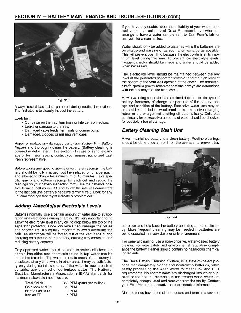
For individual cell voltage readings, place the positive lead ofthe voltmeter on the positive terminal of the cell and the nega-tive lead of the voltmeter on the negative terminal of the samecell (Fig. IV-3).
After measuring the voltage of every cell, take the specific grav-ity readings of the cell with the highest open circuit voltage andthe cell with the lowest open circuit voltage. The specific gravityreadings should confirm the state of charge of both cells andaccurately pinpoint the difference between them. If the specificgravity difference is greater than 20 points, a problem mightexist with one of the cells. Also, a cell may have internal prob-lems if the open circuit voltage is more than 0.03 volts belowthe average voltage of all the cells.
Battery InspectionBatteries should be inspected periodically to avoid damageresulting from previously undetected problems or impropermaintenance and operational procedures.
SECTION IV — BATTERY MAINTENANCE AND TROUBLESHOOTING (cont.)
Fig. IV-2
DAILY BATTERY RECORDBattery Number
Month Year
Total Cycles
DateSpecific Gravity
In OutOperator
WaterAdded
Repairs and Capacity Tests(Date, Description and Results)
Fig. IV-1
18
SECTION IV — BATTERY MAINTENANCE AND TROUBLESHOOTING (cont.)
Always record basic data gathered during routine inspections.The first step is to visually inspect the battery.
Look for:• Corrosion on the tray, terminals or intercell connectors.• Leaks or damage to the tray.• Damaged cable leads, terminals or connections.• Damaged, clogged or missing vent caps.
Repair or replace any damaged parts (see Section V — BatteryRepair) and thoroughly clean the battery. (Battery cleaning iscovered in detail later in this section.) In case of serious dam-age or for major repairs, contact your nearest authorized EastPenn representative.
Before taking any specific gravity or voltmeter readings, the bat-tery should be fully charged, but then placed on charge againand allowed to charge for a minimum of 15 minutes. Take spe-cific gravity and voltage readings for each cell and record thereadings on your battery inspection form. Use the battery’s pos-itive terminal cell as cell #1 and follow the intercell connectorsto the last cell (the battery’s negative terminal cell). Look for anyunusual readings that might indicate a problem cell.
Adding Water/Adjust Electrolyte LevelsBatteries normally lose a certain amount of water due to evapo-ration and electrolysis during charging. It’s very important not toallow the electrolyte level in any cell to drop below the top of theseparator protector, since low levels can damage the platesand shorten life. It’s equally important to avoid overfilling thecells, as electrolyte will be forced out of the vent caps duringcharging onto the top of the battery, causing tray corrosion andreducing battery capacity.
Only approved water should be used to water cells becausecertain impurities and chemicals found in tap water can beharmful to batteries. Tap water in certain areas of the country isunsuitable at any time, while in other areas it may be satisfacto-ry only during certain seasons. If the water in your area isn’tsuitable, use distilled or de-ionized water. The NationalElectrical Manufacturers Association (NEMA) standards formaximum allowable impurities are: Total Solids 350 PPM (parts per million) Chlorides and C1 25 PPM Nitrates as NO3 10 PPM Iron as FE 4 PPM
If you have any doubts about the suitability of your water, con-tact your local authorized Deka Representative who canarrange to have a water sample sent to East Penn’s lab foranalysis, for a nominal fee.
Water should only be added to batteries while the batteries areon charge and gassing or as soon after recharge as possible.This will prevent overfilling because the electrolyte is at its max-imum level during this time. To prevent low electrolyte levels,frequent checks should be made and water should be addedwhen necessary.
The electrolyte level should be maintained between the lowlevel at the perforated separator protector and the high level atthe bottom of the vent well opening of the cover. The manufac-turer’s specific gravity recommendations always are determinedwith the electrolyte at the high level.
How a watering schedule is determined depends on the type ofbattery, frequency of charge, temperature of the battery, andage and condition of the battery. Excessive water loss may becaused by shorted or weakened cells, excessive chargingrates, or the charger not shutting off automatically. Cells thatcontinually lose excessive amounts of water should be checkedfor possible internal damage.
Battery Cleaning Wash UnitA well maintained battery is a clean battery. Routine cleaningsshould be done once a month on the average, to prevent tray
corrosion and help keep the battery operating at peak efficien-cy. More frequent cleaning may be needed if batteries arebeing operated in a very dusty or dirty environment.
For general cleaning, use a non-corrosive, water~based batterycleaner. For user safety and environmental regulatory compli-ance the battery cleaner should contain no hazardous chemicalingredients.
The Deka Battery Cleaning System, is a state-of-the-art pro-cess that completely cleans and neutralizes batteries, whilesafely processing the wash water to meet EPA and DOTrequirements. No contaminants are discharged into water sup-plies or the soil; all materials in the treated wash water arecompletely encapsulated and removed from the facility. Contactyour East Penn representative for more detailed information.
Most batteries have intercell connectors and terminals covered
Fig. IV-4
Fig. IV-3

19
SECTION IV — BATTERY MAINTENANCE AND TROUBLESHOOTING (cont.)
with plastic shrouds. These should be removed prior to batterycleaning and immersed in the cleaning solution.
MAKE SURE ALL VENT PLUGS ARE TIGHTLY IN PLACEWHEN CLEANING OR WASHING BATTERIES. Check the gasescape holes in the vent plugs for dirt clogs.
For maximum effectiveness, the solution should be applied witha clean, non-metallic brush, so it can be worked under the ter-minals and intercell connectors to remove dirt and neutralizeany excess acid (Fig. IV-4). Use a low pressure hose to rinsethe battery with water until all traces of solution and loose dirtare removed.
Before placing the cleaned battery back in service, rinse andattach the intercell connector and terminal shrouds. All excessrinse water should be removed from the battery top with a lowpressure air hose or allowed to air dry.
Performing a Test DischargeTo determine if a battery can deliver its rated capacity, a testdischarge, or capacity test, can be performed. This test helpsdetermine the “health” of a battery and whether or not it shouldbe replaced.
Only experienced battery technicians should be allowed to pre-pare a battery for discharge testing and to conduct the actualdischarge test.
The test is conducted by discharging a fully charged battery atthe six hour rate until the battery voltage drops to a final voltageof 1.70 volts per cell, times the number of cells in the battery.The six hour rate in amps is a number equal to the rated capac-ity at the six hour rate divided by six hours.
By noting the time elapsed between when the battery was puton discharge and when the final voltage was reached, you candetermine whether the battery is delivering its rated capacity:1. Give the battery an equalizing charge and adjust thespecific gravity to the manufacturer’s specification, withthe electrolyte level at the bottom of the vent well.Always temperature correct the gravity readings.
2. Start the test and record the starting time.3. Record individual cell voltages and overall battery volt-ages during the first hour at 10 minutes, 30 minutes andthen 60 minutes. After the first hour, take hourly readingsuntil the first cell voltage reaches 1.75 volts per cell.From this point on, record the voltage of the cells every 5minutes.
4. Carefully monitor the voltage of the low cells and as thevoltage of each cell drops below termination value,record the time.
5. When the majority of the cells reach termination value,stop the test. Don’t let any cells go into reversal.
6. Use this formula to calculate capacity delivery:
minutes to final voltage 360 minutes x 100
For example, if the test was terminated after 336 minutes,the capacity percentage would be 93%7. After termination of the test, immediately record the spe-cific gravity of each cell. If all the cells have uniformspecific gravity and the battery delivers 80% or more ofits rated capacity, 288 minutes, it can be returned to ser-
vice. If the test indicates that less than 80% of the bat-tery’s rated capacity is being delivered, the batteryshould be either repaired or replaced, depending uponits age and overall condition.
For more detailed information on capacity testing, contact EastPenn Manufacturing Company or your local authorized DekaRepresentative.
Correcting a Sulfated BatteryIf batteries are not operating full shifts, heat while on chargeand after charge, and if temperature corrected specific gravityreadings are below the manufacturer’s specifications, the bat-teries may be sulfated.
To restore a sulfated battery to good condition, carefully followthis procedure:1. Thoroughly clean the battery.2. Add water to bring the electrolyte to the proper level in allcells.
3. Charge the battery at the prescribed finishing rate untilthe specific gravity shows no change for a three-hourperiod with readings taken hourly. Record on-chargevoltage and specific gravity readings. Temperature cor-rect the specific gravity readings using the chart (Table3-1) in Section III. If the temperature rises to above115°F (46°C) at any time, stop the charger and allow thebattery to cool to 90°F (32°C) or lower, then continue thecharge and monitor the specific gravity as describedabove. If the charger is automatic, be sure it is capableof charging the battery at the prescribed finish rate. Aconstant current charger that can maintain the correctfinish rate is preferred. If the battery is badly sulfated, thespecific gravity may only rise 30 to 40 points (0.30 to0.40) during the first charge.
4. Fully discharge the battery.5. Repeat step #3 until the specific gravity remainsunchanged for three hours. In extreme cases of sulfa-tion, two or more discharges and recharges, per theabove instructions, may be necessary to restore the bat-tery to full capacity. (Percent capacity capable of beingrestored is a function of overall battery age and condi-tion). If the battery hasn’t responded, it may be sulfatedbeyond repair and should be replaced. If the specificgravity rises to within ten points of a fully charged bat-tery, then place the battery back into normal service.
6. Before condemning the battery, one last check should bemade to make sure the battery has not simply lost acidby dumping or over-filling. Adjust the specific gravity tothe manufacturer’s specification (see Table 4-1 -Procedure for Adjusting the Specific Gravity of theElectrolyte of a Battery).
Conduct a capacity test. If the battery delivers over 90% ofits rated six hour capacity, the battery may be returned toservice. If the capacity on discharge remains low, the bat-tery should be replaced.
IMPORTANT - Only experienced battery technicians shouldperform the above technique.

20
SECTION IV — BATTERY MAINTENANCE AND TROUBLESHOOTING (cont.)
Table 4-1PROCEDURE FOR ADJUSTING THE SPECIFIC GRAVITY
OF THE ELECTROLYTE OF A BATTERY
1. When it is necessary to raise or lower the specific gravityof the electrolyte of a battery to the manufacturer’s rec-ommended specific gravity, follow the procedure givenbelow.
2. The recommended specific gravity for some of the Dekaindustrial battery styles is shown in Table 1. For example,a 12-D85-13 battery would have a recommended specificgravity of 1.290.
TABLE I Recommended Battery Style Specific Gravity or Type at 77°F D prefix 1.290 H prefix 1.300 M prefix 1.250 P prefix 1.325 DL/DLU 1.250
3. This specific gravity is always determined when the bat-tery is fully charged, with the electrolyte level at thebottom of the vent well tube while the battery is on chargeat the finish rate or less.
4. The term “finish rate” refers to a constant charging rate inamps which is equal to 5% (.05) of the rated six hourcapacity (8 hour for diesels) of the battery. For example,the finish rate of a D100-13 battery with a rated 6 hourcapacity of 600 AH (ampere hours) would be: 600 x .05 =30 amps.
5. The battery should first be given an equalizing charge tomake sure it is fully charged. An “equalizing charge” is anextended charge at the finish rate after completion of aregular charge. Usually 3 or 4 hours until four voltage andspecific gravity readings, corrected for temperature, taken1/2 hour apart, remain constant.
6. Since the electrolyte temperature will affect the on-chargevoltage and specific gravity readings, all readings mustbe corrected for temperature to a standard 77°F. Refer toSection III, Table 3-1, Specific Gravity TemperatureCorrections.
7. Care should be taken during equalizing charging and acidadjustment charging to make sure that the electrolytetemperature does not exceed 115°F.
8. As it is necessary to add acid to the cell in order to raisethe specific gravity of the electrolyte, sulfuric acid of 1.400specific gravity shall be used. It should be rememberedthat 1.400 specific gravity sulfuric acid has an acid con-tent of 50.5% by weight and is potentially a verydangerous material to the person using it. All standardsafety precautions should be taken, especially thosewhich will protect personnel from splashes into the eyesand onto the skin. Acid resistant gloves, apron, boots,face shield and /or goggles should be standard equip-ment. Running water from a hose and/or ready access toan eye-wash fountain is important for safety.
9. With the battery on charge at a constant finish rate,remove between a 1/4" to 1/2" of electrolyte with asyringe for every 5 points of change required. This is onlya rough approximation since the amount of change willvary with every cell type with a greater change on theshorter cells and a smaller change on the taller cells.Replace the electrolyte removed with 1.400 specificgravity sulfuric acid. Continue to charge the battery afteracid addition until the specific gravity becomes constant,about 1/2 to 1 hour.
10. Repeat the above procedure until the specific gravity ofthe electrolyte, corrected for temperature, reaches thedesired value.
11. If the specific gravity must be lowered instead of raised,water can be used instead of 1.400 specific gravity acid inthe procedure given above.

21
SECTION IV — BATTERY MAINTENANCE AND TROUBLESHOOTING (cont.)
Table 4-2STORAGE BATTERY TROUBLESHOOTING CHART
Battery overheatsduring charge
POSSIBLE CAUSE
1. Malfunctioning Charging Equipment
2. Charging equipment out of adjustment
3. Defective or weak cell(s)
4. Battery worn out and beyond economicalrepair
5. High resistance connection within battery
6. Low electrolyte level
7. Battery charged in the vehicle with batterycompartment closed or the tray coverclosed
8. Battery over 100 degrees F when placedon charge
Symptoms POSSIBLE REMEDY
1. Replace or repair defective charger parts(timer, voltage sensitive relay, control board,etc.)
2. Adjust start and/or finish charging rates
3. Replace or repair problem cell(s)
4. Replace battery
5. Check for hot wires, cells, intercell connec-tors, charging plugs, etc. Repair or replacedefective component(s)
6. Add water; just cover separator protectorwhen discharged
7. Open the compartment during charge orcharge the battery out of the unit with thetray cover opened
8. Allow battery to cool below 90 degrees Fbefore charging
Battery overheatsduring charge
Battery not complet-ing full work shift
1. See causes 3 through 8 above
2. Worn out bearings, brakes dragging, orother vehicle problem causing high dis-charge rates
3. Overdischarge of battery
1. Battery not fully charged before placedinto operation
2. Weak, leaking or defective cell(s) in battery
3. Ground or shorts in the battery
4. Battery worn out and beyond economicalrepair
5. Battery too small for job
6. Electrical or mechanical problem
1. See remedies 3 through 8 above
2. Repair or replace defective unit problems
3. a. Require drivers to return battery forrecharge when vehicle begins to slowdown.
b. Put more batteries into service
1. See that battery has reached full charge specific gravity before placing into operation
2. Repair or replace cell(s) or battery
3. Remove grounds or shorts
4. Replace battery with equal or higher capacitybattery
5. a. Replace battery with one having highercapacity
b. Purchase extra batteries (with highercapacity if possible) and change themmore frequently
6. Troubleshoot vehicle and repair
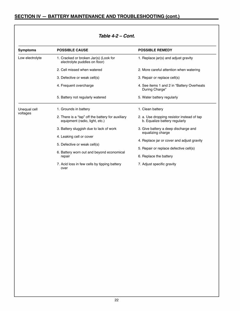
22
SECTION IV — BATTERY MAINTENANCE AND TROUBLESHOOTING (cont.)
Table 4-2 – Cont.
Low electrolyte
Unequal cell voltages
POSSIBLE CAUSE
1. Cracked or broken Jar(s) (Look for electrolyte puddles on floor)
2. Cell missed when watered
3. Defective or weak cell(s)
4. Frequent overcharge
5. Battery not regularly watered
1. Grounds in battery
2. There is a “tap” off the battery for auxiliaryequipment (radio, light, etc.)
3. Battery sluggish due to lack of work
4. Leaking cell or cover
5. Defective or weak cell(s)
6. Battery worn out and beyond economicalrepair
7. Acid loss in few cells by tipping batteryover
Symptoms POSSIBLE REMEDY
1. Replace jar(s) and adjust gravity
2. More careful attention when watering
3. Repair or replace cell(s)
4. See items 1 and 2 in “Battery OverheatsDuring Charge”
5. Water battery regularly
1. Clean battery
2. a. Use dropping resistor instead of tapb. Equalize battery regularly
3. Give battery a deep discharge and equalizing charge
4. Replace jar or cover and adjust gravity
5. Repair or replace defective cell(s)
6. Replace the battery
7. Adjust specific gravity
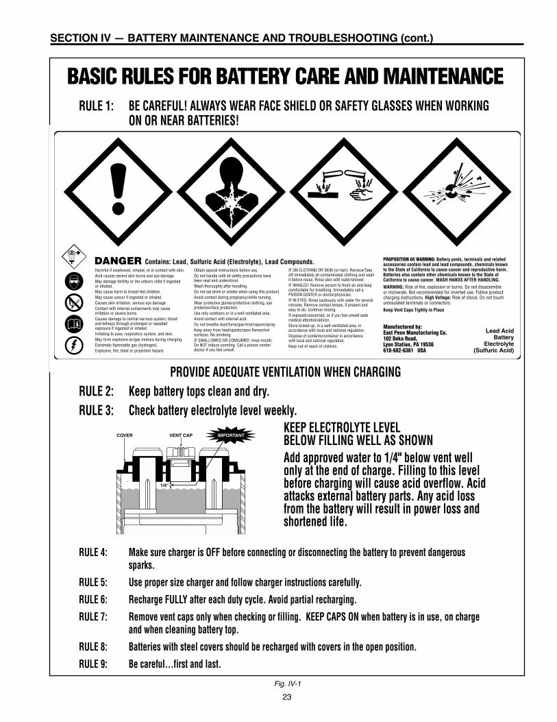
23
SECTION IV — BATTERY MAINTENANCE AND TROUBLESHOOTING (cont.)
Fig. IV-1
Manufactured by: East Penn Manufacturing Co.102 Deka Road, Lyon Station, PA 19536 610-682-6361 USA
PROPOSITION 65 WARNING: Battery posts, terminals and related accessories contain lead and lead compounds, chemicals known to the State of California to cause cancer and reproductive harm. Batteries also contain other chemicals known to the State of California to cause cancer. WASH HANDS AFTER HANDLING.WARNING: Risk of fire, explosion or burns. Do not disassemble or incinerate. Not recommended for inverted use. Follow product charging instructions. High Voltage: Risk of shock. Do not touch uninsulated terminals or connectors. Keep Vent Caps Tightly in Place
Harmful if swallowed, inhaled, or in contact with skin.Acid causes severe skin burns and eye damage. May damage fertility or the unborn child if ingested or inhaled.May cause harm to breast-fed children.May cause cancer if ingested or inhaled.Causes skin irritation, serious eye damage. Contact with internal components may cause irritation or severe burns. Causes damage to central nervous system, blood and kidneys through prolonged or repeated exposure if ingested or inhaled.Irritating to eyes, respiratory system, and skin.May form explosive air/gas mixture during charging.Extremely flammable gas (hydrogen). Explosive, fire, blast or projection hazard.
Obtain special instructions before use.Do not handle until all safety precautions have been read and understood.Wash thoroughly after handling.Do not eat drink or smoke when using this product.Avoid contact during pregnancy/while nursing.Wear protective gloves/protective clothing, eye protection/face protection. Use only outdoors or in a well-ventilated area.Avoid contact with internal acid.Do not breathe dust/fume/gas/mist/vapors/spray.Keep away from heat/sparks/open flames/hot surfaces. No smoking.IF SWALLOWED OR CONSUMED: rinse mouth. Do NOT induce vomiting. Call a poison center/doctor if you feel unwell.
IF ON CLOTHING OR SKIN (or hair): Remove/Take off immediately all contaminated clothing and wash it before reuse. Rinse skin with water/shower. IF INHALED: Remove person to fresh air and keep comfortable for breathing. Immediately call a POISON CENTER or doctor/physician.IF IN EYES: Rinse cautiously with water for several minutes. Remove contact lenses, if present and easy to do. Continue rinsing. If exposed/concerned, or if you feel unwell seek medical attention/advice.Store locked up, in a well-ventilated area, in accordance with local and national regulation.Dispose of contents/container in accordance with local and national regulation.Keep out of reach of children.
Lead AcidBattery
Electrolyte(Sulfuric Acid)
DANGER Contains: Lead, Sulfuric Acid (Electrolyte), Lead Compounds.
RULE 1: BE CAREFUL! ALWAYS WEAR FACE SHIELD OR SAFETY GLASSES WHEN WORKINGON OR NEAR BATTERIES!
PROVIDE ADEQUATE VENTILATION WHEN CHARGINGRULE 2: Keep battery tops clean and dry.RULE 3: Check battery electrolyte level weekly.
KEEP ELECTROLYTE LEVEL BELOW FILLING WELL AS SHOWNAdd approved water to 1/4" below vent wellonly at the end of charge. Filling to this levelbefore charging will cause acid overflow. Acidattacks external battery parts. Any acid lossfrom the battery will result in power loss andshortened life.
RULE 4: Make sure charger is OFF before connecting or disconnecting the battery to prevent dangeroussparks.
RULE 5: Use proper size charger and follow charger instructions carefully.
RULE 6: Recharge FULLY after each duty cycle. Avoid partial recharging.
RULE 7: Remove vent caps only when checking or filling. KEEP CAPS ON when battery is in use, on chargeand when cleaning battery top.
RULE 8: Batteries with steel covers should be recharged with covers in the open position.
RULE 9: Be careful…first and last.
BASIC RULES FOR BATTERY CARE AND MAINTENANCE
1/4"
COVER VENT CAP IMPORTANT

In the lead-acid battery, according to basic electrochemicalprincipals, complete sealing cannot be accomplished becausethe generation of hydrogen cannot be completely avoided. Thevalve has to open periodically to let small amounts of gas,mainly hydrogen, escape from the cell. Otherwise, the internalpressure would exceed tolerable limits. Gradual water loss isconnected with this gas evolution, and this water loss causesslight changes in the cell parameters during service life. But therate of water loss can be kept so low that the initial amount ofelectrolyte is sufficient for a service life of five years or more.
Valve-regulated lead-acid batteries can be constructed usinggelled electrolyte as well as absorbent glass mat separators(AGM). Which immobilizing method is used, often dependsupon the application and manufacturer. For deep cycle applica-tions such as motive power, gelled electrolyte is more suitable.The gelled electrolyte requires a separator to prevent short-cir-cuits between the electrodes. This additional separator causesadditional resistance. Therefore, the internal resistance of com-parable batteries is slightly higher with gelled electrolyte, thussuch batteries are not as suitable in extreme high load currentwith short duration requirements such as UPS applications.
Operation of a Gel CellDuring the overcharge period of the recharge, oxygen is gener-ated from the positive plates in all lead-acid batteries. Thisoxygen is trapped in the gel cell by a special vent valve forcingthe oxygen to the negative plate through tiny fissures or cracksin the gelled electrolyte. When the oxygen contacts the nega-tive active mass (sponge lead), it oxidizes the negative activemass to lead oxide. The lead oxide reacts with the sulfuric acidto form lead sulfate and water. At the same time, during thecharging process, this lead sulfate is converted back to spongelead and sulfuric acid. This “recombination”’ process preventswater loss.
The vent valve is critical to the performance of the gel cell. Thecell must maintain a positive internal pressure. Otherwise, theoxygen will escape, and the cell will dry out and not perform.
In addition the valve must safely release any excess pressurethat may be produced during overcharging, or else the cellwould be irreparably damaged.
It’s important to note that a gel cell must never be opened once itleaves the factory. Opening the cell will allow excess atmospher-ic oxygen to enter the cell and discharge the negative plates.This will cause an imbalance that will destroy the recombinationchemistry. This imbalance of chemistry will permanently dam-age the cell beyond repair.
Charging a Gel CellWhile our gel cell will accept a charge extremely well due to itsinternal resistance, any battery will be damaged by continualunder-or overcharging. Capacity is reduced and life is short-ened.
Abusive overcharging is especially harmful to gel cells becauseof their sealed design. Abusive overcharging dries out the elec-trolyte by driving the oxygen and hydrogen out of the batterythrough the sealing vents. Performance and life are reduced.
If a battery is continually undercharged, a power-robbing layerof sulfate can build up on the positive plate, which acts as abarrier to electron flow. Premature plate shedding can alsooccur. Performance is reduced and life is shortened.
Therefore, it is critical to use a charger that limits voltage to2.55 volts per cell at 77°F ± 2° at the end of charge. If thecharger can reduce the voltage as the temperature rises, orincrease the voltage as the temperature decreases, this willhelp to prevent under-or overcharging. The warranty is void ifimproperly charged. The supplied on board charger forGelmate, or the Ultra Charger with the D.S.G. Sealed Lead-Acid Battery charge curve profile, or any other EPM-approvedmotive power gel cell charger must be utilized to recharge gelcell batteries. Constant current charges or ferroesonantcharges should NEVER be used on gel cell batteries. (See Fig.V-2).
24
SECTION V – VALVE REGULATED LEAD-ACID BATTERIES
Ultra Charge Deka Dominator Battery Curve
Voltage-Time, 6 hrs. after 80% only.Vlid & Vgas temperature Compensated (-10mV/cell/3°F)
Vlid = 2.55V/C
I Fin = 1.5A/100AH
Vgas = 2.33V/C
80% starts after chargecurrent drops below8.2A/100AH
Ista
rt =
16.
3A/1
00A
HVolts
/Cel
l
Amps/100AH
2.7
2.6
2.5
2.4
2.3
2.2
2.1
20 2 4 5 8 10 12 14 16 18
Fig. V-1
Fig. V-2

25
SECTION V – VALVE REGULATED LEAD-ACID BATTERIES (cont.)
OPERATING INSTRUCTIONSSEALED VALVE REGULATED LEAD ACID (SVRLA)
GELLED ELECTROLYTE BATTERIES
WARNING: Charging shall be performed by using only the supplied on-board charger forGelmate, or the Ultra Charge Charger with the D.S.G. Sealed Lead-Acid Batterycharge curve profile, or any other EPM-approved motive power gel electrolytecharger.The valve-regulated vent should not be removed. Removal of the vent willadversely affect the battery’s life and performance.The battery’s warranty will be void if these guidelines are not followed.
1. Upon receipt of the battery, if there are signs of rough handling, or exposed electrolyte, or looseor missing vent(s), file a claim with the carrier and advise your East Penn representative.
2. Check the nameplate of your charger against the nameplate of the battery to make sure they bothshow the same voltage and that the six-hour ampere hour capacity of the battery falls within therecharge range of the charger.
3. The “Battery Type Identification” shown on the battery (E, EO), should match the “Battery TypeIdentification” specified on the truck nameplate.
4. Make sure that the battery “SERVICE WEIGHT,” which is stamped below the lifting hole in thesteel tray, falls within the battery weight range shown on the truck nameplate. East PennManufacturing Co., Inc. cannot be responsible for determining that the battery weight issufficient to counterbalance your particular truck.
5. The battery should receive an equalizing charge prior to placing the battery into service. Thebattery shall be charged by using the supplied charger. The equalizing charge is complete whenthe charger automatically terminates. No other charger should be used unless approved by EastPenn. Doing so will void the warranty. If the voltage falls below 2.14 volts or at a minimum ofevery 6 weeks the battery should receive a freshening change.
6. The battery shall be placed on charge at the end of the work shift and the charge should continueuntil the charger terminates the charge automatically. All vents should be unobstructed andsecurely tightened. The steel tray cover or the truck compartment should be kept open during theentire duration of charge.
7. Overcharging and undercharging a sealed gel electrolyte battery will greatly affect the life of thebattery.
8. Measuring the open circuit voltage provides a way to determine the state of charge of the battery.The open circuit voltage shall be taken with a voltmeter. Voltage measurements should be takenno earlier than 4 hours on open circuit following a charge.
STATE OF CHARGE VS. OPEN CIRCUIT % Charge Open Circuit Voltage 100 ……………………… 2.15 – 2.18 75 …………………………… 2.12 50 …………………………… 2.07 25 …………………………… 2.01 0 …………………………… 1.97
9. EPM recommends when lifting a battery that an insulated lifting beam be used. Also, makecertain that the lifting hooks are the correct size and are properly aligned with the holes in thelifting ears of the tray prior to hoisting a battery.
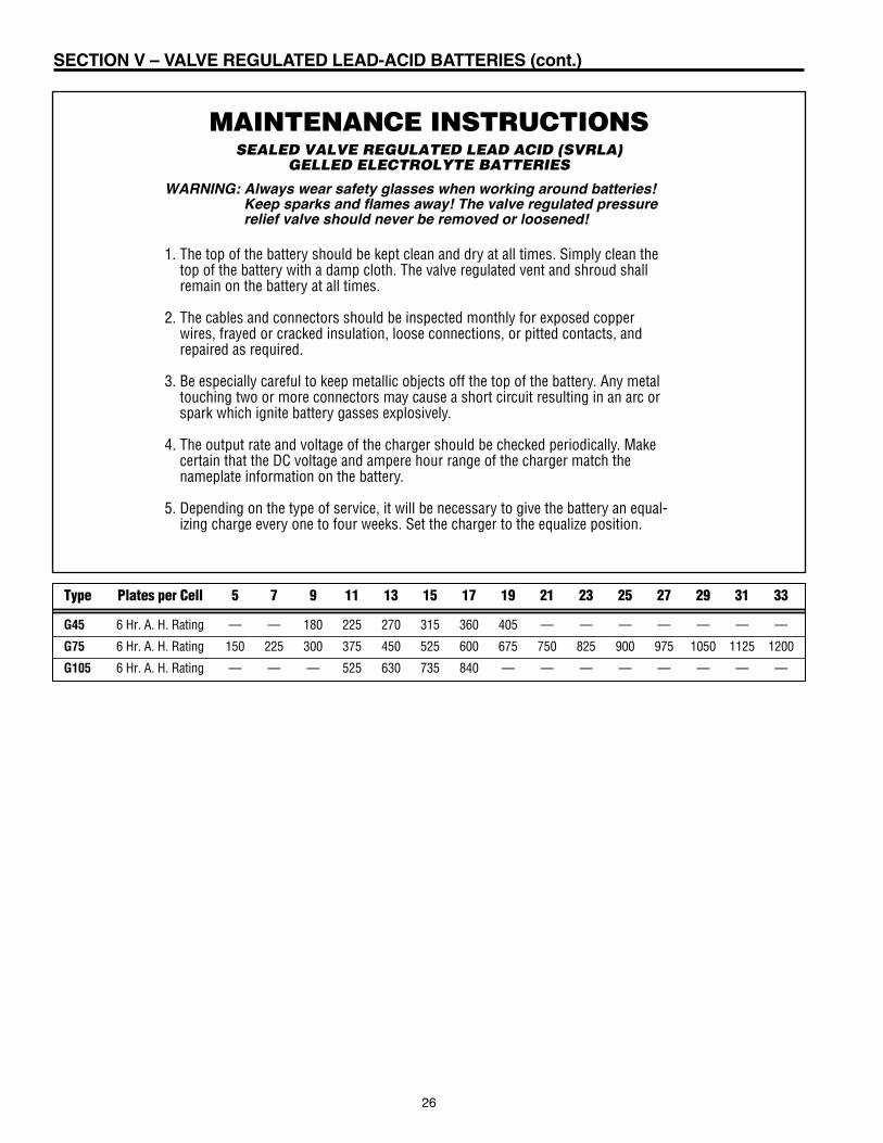
26
SECTION V – VALVE REGULATED LEAD-ACID BATTERIES (cont.)
MAINTENANCE INSTRUCTIONSSEALED VALVE REGULATED LEAD ACID (SVRLA)
GELLED ELECTROLYTE BATTERIES
WARNING: Always wear safety glasses when working around batteries!Keep sparks and flames away! The valve regulated pressurerelief valve should never be removed or loosened!
1. The top of the battery should be kept clean and dry at all times. Simply clean thetop of the battery with a damp cloth. The valve regulated vent and shroud shallremain on the battery at all times.
2. The cables and connectors should be inspected monthly for exposed copperwires, frayed or cracked insulation, loose connections, or pitted contacts, andrepaired as required.
3. Be especially careful to keep metallic objects off the top of the battery. Any metaltouching two or more connectors may cause a short circuit resulting in an arc orspark which ignite battery gasses explosively.
4. The output rate and voltage of the charger should be checked periodically. Makecertain that the DC voltage and ampere hour range of the charger match thenameplate information on the battery.
5. Depending on the type of service, it will be necessary to give the battery an equal-izing charge every one to four weeks. Set the charger to the equalize position.
Type Plates per Cell 5 7 9 11 13 15 17 19 21 23 25 27 29 31 33
G45 6 Hr. A. H. Rating — — 180 225 270 315 360 405 — — — — — — —
G75 6 Hr. A. H. Rating 150 225 300 375 450 525 600 675 750 825 900 975 1050 1125 1200
G105 6 Hr. A. H. Rating — — — 525 630 735 840 — — — — — — — —
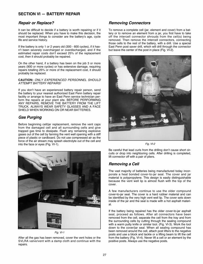
Repair or Replace? It can be difficult to decide if a battery is worth repairing or if itshould be replaced. When you have to make this decision, themost important things to consider are the battery’s age, cyclelife and service history.
If the battery is only 1 or 2 years old (300 - 600 cycles), if it has-n’t been severely overcharged or overdischarged, and if theestimated repair costs don’t exceed 25% of the replacementcost, then it should probably be repaired.
On the other hand, if a battery has been on the job 3 or moreyears (900 or more cycles) or has extensive damage, requiringrepairs totalling 25% or more of the replacement cost, it shouldprobably be replaced.
CAUTION: ONLY EXPERIENCED PERSONNEL SHOULDATTEMPT BATTERY REPAIRS!
If you don’t have an experienced battery repair person, sendthe battery to your nearest authorized East Penn battery repairfacility or arrange to have an East Penn service technician per-form the repairs at your plant site. BEFORE PERFORMINGANY REPAIRS, REMOVE THE BATTERY FROM THE LIFTTRUCK. ALWAYS WEAR SAFETY GLASSES AND A FACESHIELD WHEN WORKING ON OR NEAR BATTERIES.
Gas PurgingBefore beginning cell/jar replacement, remove the vent capsfrom the damaged cell and all surrounding cells and givetrapped gas time to dissipate. Flush any remaining explosivegases out of the cell by fanning the vent well opening with a stiffpiece of plastic or cardboard. Do not use compressed air as theforce of the air stream may splash electrolyte out of the cell andinto the face or eyes (Fig. VI-1).
After all the gas has been removed, cover the vent holes or theSVLRA valve/vent with a damp cloth and continue with therepairs.
Removing ConnectorsTo remove a complete cell (jar, element and cover) from a bat-tery or to remove an element from a jar, you first have to takeoff the intercell connector shrouds from the cell(s) beingremoved. Then remove the intercell connectors, connectingthose cells to the rest of the battery, with a drill. Use a specialEast Penn post saver drill, which will drill through the connectorbut leave the center of the post in place (Fig. VI-2).
Be careful that lead curls from the drilling don’t cause short cir-cuits or drop into neighboring cells. After drilling is completed,lift connector off with a pair of pliers.
Removing a CellThe vast majority of batteries being manufactured today incor-porate a heat bonded cover-to-jar seal. The cover and jarmaterial is polypropylene. This design is easily distinguishablebecause the vent well lip is almost flush with the top of thecover.
A few manufacturers continue to use the older compoundcover-to-jar seal. The cover is a hard rubber material and canbe identified by the very high vent well lip. The cover sets downinside of the jar and the seal is made with a hot asphalt materi-al.
If the battery being repaired has the older cover-to-jar asphaltseal, proceed as follows. After all connectors have beenremoved from the cell, separate the cell from the tray and fromthe surrounding cells by cutting through the sealing compoundwith a warm putty knife or similar tool. (Fig. VI-3). Work the tooldown to the cover/jar seal. When all sealing compound hasbeen removed around the cell, attach post lifters to the negativeposts and use a block and tackle or a lifting beam to lift the cellfrom the battery (Fig. VI-4). Never lift a cell or an element by thepositive posts. Always use the negative posts.
27
SECTION VI — BATTERY REPAIR
Fig. VI-1
Fig. VI-2
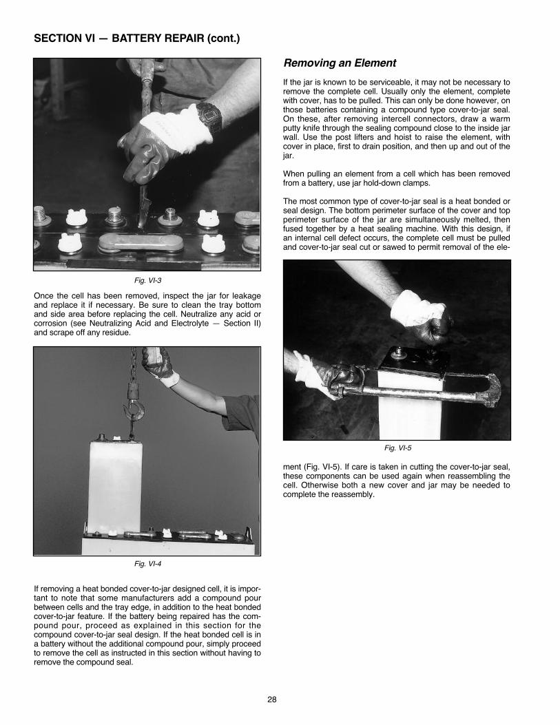
Once the cell has been removed, inspect the jar for leakageand replace it if necessary. Be sure to clean the tray bottomand side area before replacing the cell. Neutralize any acid orcorrosion (see Neutralizing Acid and Electrolyte — Section II)and scrape off any residue.
If removing a heat bonded cover-to-jar designed cell, it is impor-tant to note that some manufacturers add a compound pourbetween cells and the tray edge, in addition to the heat bondedcover-to-jar feature. If the battery being repaired has the com-pound pour, proceed as explained in this section for thecompound cover-to-jar seal design. If the heat bonded cell is ina battery without the additional compound pour, simply proceedto remove the cell as instructed in this section without having toremove the compound seal.
Removing an ElementIf the jar is known to be serviceable, it may not be necessary toremove the complete cell. Usually only the element, completewith cover, has to be pulled. This can only be done however, onthose batteries containing a compound type cover-to-jar seal.On these, after removing intercell connectors, draw a warmputty knife through the sealing compound close to the inside jarwall. Use the post lifters and hoist to raise the element, withcover in place, first to drain position, and then up and out of thejar.
When pulling an element from a cell which has been removedfrom a battery, use jar hold-down clamps.
The most common type of cover-to-jar seal is a heat bonded orseal design. The bottom perimeter surface of the cover and topperimeter surface of the jar are simultaneously melted, thenfused together by a heat sealing machine. With this design, ifan internal cell defect occurs, the complete cell must be pulledand cover-to-jar seal cut or sawed to permit removal of the ele-
ment (Fig. VI-5). If care is taken in cutting the cover-to-jar seal,these components can be used again when reassembling thecell. Otherwise both a new cover and jar may be needed tocomplete the reassembly.
28
SECTION VI — BATTERY REPAIR (cont.)
Fig. VI-3
Fig. VI-4
Fig. VI-5

When removing an element, lift it halfway out of the jar and holdit at this position until most of the electrolyte has drained off(Fig. VI-6). Then raise the element to clear the top of the jar. Donot, unless absolutely necessary, expose an element to airlonger than five minutes. Oxygen in the air combines with theactive material in the negative plates, causing them to oxidizeand heat. If the exposure persists, negatives will discharge.While the element is out of the jar, check the sediment chamberin the bottom of the jar. If it is full of sediment material, the cellwill probably have to be replaced, if not now, in the near future.
Plate and separator edges may be inspected while the elementis suspended above the jar. A more thorough inspection of sep-arators, plate insulation, grids, and active materials may beindicated. If so, lay the element on its side on a clean non-metallic surface, The plates should be at right angles to thetable surface so the element can be fanned slightly to permitthe removal of separators if required (Fig. VI-7).
When reinstalling separators, make certain that the flat side ofthe separator is against the negative plate and the ribbed sideis facing the positive. They should be pushed up until they areflush with the bottom of the element and they should projectequally on each side of the plates.
Before installing an element in a previously used jar, wash outany sediment which may have accumulated in the bottom of thejar and clean all compound from around the inside of the topedge (if the battery has a compound seal).
Clamp the element, if necessary, when reinstalling it in the jar.Make certain the element is entering the jar properly and thatthe plates are at right angles to the plate rest support ribs in thebottom. When installing an element with a hard rubber, com-pound sealed cover attached, use a putty knife to guide the lipof the cover past the top edges of the jar.
Reassembling the BatteryIf the cell being reassembled, has a heat seal cover-to-jardesign, and if care was taken cutting the seal when removingthe element, the cover and jar can probably be heat sealedagain, If not, a new cover and jar will be needed, Be sure toreinstall the cover with the positive post(s) protruding throughthe cover post holes marked positive (+). If the cell designincorporates floating positive post seals, push them down firmlyover the positive posts until they seat flush on top of the coverafter sealing the cover to the jar. Some designs have leadinserts or bushings already molded into both the negative andpositive cover post holes. In both cases, these floating postseals and/or lead cover bushings are welded or burned to theterminal posts to prevent electrolyte leakage around the postsusing a post burning ring (Fig. VI-8). Before using an openflame to weld the posts and cover bushings, you must onceagain eliminate any gas from the repaired cell and all surround-ing cells. (See Gas Purging in this section.)
Since special techniques must be used when resealing thecover to jar, East Penn recommends that these cover-to-jarseals not be repaired in the field. Instead, such repairs shouldbe made in authorized East Penn service stations only.
If the cell being reassembled has the sealing compound, cover-to-jar seal, an asphalt type compound is applied to seal thecover to the jar. These covers will have lead bushings moldedinto both the positive and negative posts. Be sure to reinstallthe cover with the positive post(s) protruding through the coverpost holes marked positive (+). These cover bushings are weld-ed or burned to the terminal posts to prevent electrolyteleakage around the posts, using a post burning ring.
29
SECTION VI — BATTERY REPAIR (cont.)
Fig. VI-6
Fig. VI-7
Fig. VI-8
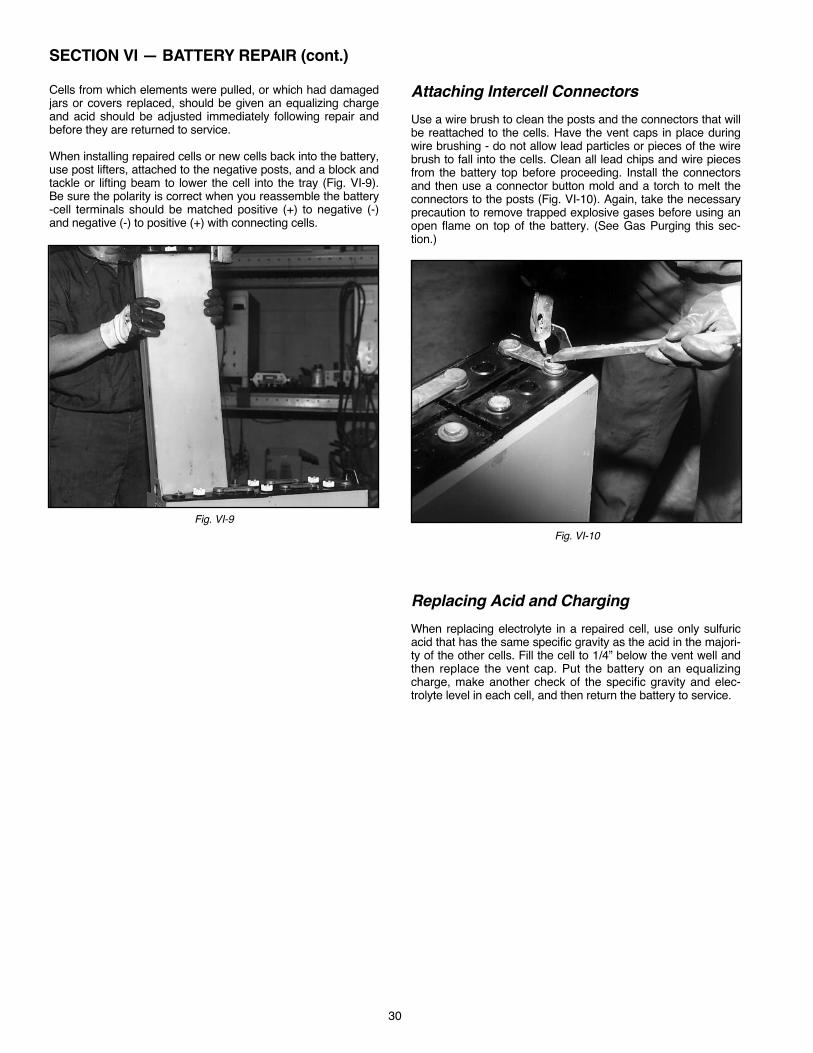
Cells from which elements were pulled, or which had damagedjars or covers replaced, should be given an equalizing chargeand acid should be adjusted immediately following repair andbefore they are returned to service.
When installing repaired cells or new cells back into the battery,use post lifters, attached to the negative posts, and a block andtackle or lifting beam to lower the cell into the tray (Fig. VI-9).Be sure the polarity is correct when you reassemble the battery-cell terminals should be matched positive (+) to negative (-)and negative (-) to positive (+) with connecting cells.
Attaching Intercell ConnectorsUse a wire brush to clean the posts and the connectors that willbe reattached to the cells. Have the vent caps in place duringwire brushing - do not allow lead particles or pieces of the wirebrush to fall into the cells. Clean all lead chips and wire piecesfrom the battery top before proceeding. Install the connectorsand then use a connector button mold and a torch to melt theconnectors to the posts (Fig. VI-10). Again, take the necessaryprecaution to remove trapped explosive gases before using anopen flame on top of the battery. (See Gas Purging this sec-tion.)
Replacing Acid and ChargingWhen replacing electrolyte in a repaired cell, use only sulfuricacid that has the same specific gravity as the acid in the majori-ty of the other cells. Fill the cell to 1/4” below the vent well andthen replace the vent cap. Put the battery on an equalizingcharge, make another check of the specific gravity and elec-trolyte level in each cell, and then return the battery to service.
30
SECTION VI — BATTERY REPAIR (cont.)
Fig. VI-9Fig. VI-10

31
GLOSSARYAcid In the lead acid storage battery industry, “acid” implies “sulfuric acid”, and isused to describe the electrolyte or liquid inthe cell.
Active Materials The materials in a batterywhich react chemically to produce electricalenergy. In a lead-acid battery the activematerials are lead peroxide (positive) andsponge lead (negative).
Activation Process for making a drycharged cel l funct ional by introducing electrolyte.
Air Oxidized A charged negative plate thathas been removed from the electrolyte andpermitted to discharge in an air atmospherewith the evolution of heat. Plates so treatedmust be recharged before they are capableof producing any useful electrical energy.
Alloy A combination of two or more metals,as a mixture, solution or compound. See“ANTIMONIAL LEAD ALLOY”, “CALCIUMLEAD ALLOY”.
Ambient Temperature The temperature ofthe surrounding cooling medium, such as gasor liquid, which comes into contact with theheated parts of the apparatus, usually refersto room or air temp.
Alternating Current An electric, pulsatingcurrent, in which the direction of flow is rapidlychanged, so that a terminal becomes in rapidsuccession positive then negative.
Ammeter An ammeter is an instrument formeasuring electr ical current. See also“AMPERE-HOUR METER”.
Ampacity Current carrying capacity inamperes.
Ampere The practical unit of electric currentthat is equivalent to the steady state currentproduced by one volt applied across a resis-tance of one ohm. It is one tenth of anabampere.
Ampere-Hour A measure of the volume ofelectricity, being one ampere for one hour, or3600 coulombs. It is used to express batterycapacity, and is registered by an amperehour meter, or is obtained by multiplying thecurrent in amperes by the length of time thatthe current is maintained.
Ampere-Hour Capacity The number ofampere-hours which can be delivered underspecified conditions as to temperature, rateof discharge, and final voltage.
Ampere-Hour Efficiency The electrochemi-cal efficiency expressed as the ratio of theampere-hours output to the ampere-hoursinput required for the recharge.
Ampere-Hour Meter An instrument that reg-isters the quantity of electr ici ty inampere-hours.
Assembly 1. The process of combining thevarious parts of cells and batteries into thefinished product. 2. Any particular arrange-ment of cells, connectors, and terminals toform a battery suited for a desired applica-tion.
Battery (Storage) A storage battery is a con-nected group of two or more storage cells(common usage permits this term to beapplied to a single cell used independently).Batteries are sometimes referred to as“Accumulators” since electric energy is accu-mulated by chemical reaction.
Bayonet Vent A term originally applied to adesign of quarter turn vent plug the lowerportion of which resembles a bayonet, bothin appearance and locking arrangement.
Boost Cells Cells with higher capacity thanthe tests cells which are used to help main-tain constant discharge current in a manualdischarge test.
Boost Charge A partial charge given to astorage battery usually at a high rate for ashort period. It is employed in motive powerservice when the capacity of a battery is notsufficient for a full day’s work.
Boot Plastic piece used at foot of plate,especially a wrapped plate, for retention andinsulation.
Bridge The ribs or elements supportingstructure, molded, or cut to fit into the bottomof a ribless jar or container in order to pro-vide sediment space under the elementthereby preventing short circuits.
Burning The welding together of two or morelead parts such as plates, straps, connector;by means of heat and in some cases, addi-tional metal supplied by a stick called aburning strip.
Burning Center The center-to-center dis-tance between adjacent plates of the samepolarity.
Burning Stick A lead stick of convenient sizeused as a supply of joining metal in leadburning.
Button The finished “button shaped” areaproduced on the top surface of a connectoror terminal by the post burning operation.
Cadmium (Cd) A metallic element highlyresistant to corrosion, used as a protectiveplating on certain steel parts and fittings.
Cadmium Electrode A third electrode forseparate measurements of the electrodepotential of positive and negative plategroups.
Calcium Lead Alloy A lead base alloy that incertain applications can be used for batteryparts in place of antimonial lead alloys Mostcommon use is in stationary cells.
CapacitySee “AMPERE HOUR CAPACITY”.
Capacity Test A test wherein the battery isdischarged at constant current at room tem-perature to a cutoff voltage of usually 1.70volts/cell.
Carbon Burning Outfit A metallic rod andinsulated handle, mounting a pointed carbonrod; used for lead burning on service loca-tions where the usual gas flame equipment isnot available.
Carboy A large cylindrical container or bottleof plastic or glass used to ship acid.
Cast To form a molten substance into a defi-nite shape by pouring or forcing the liquidmaterial into a mold and allowing it to solidify(freeze).
Casting A metallic item, such as one or moregrids, straps or connectors; produced bypouring or forcing molten metal into a moldand allowing it to solidify.
Cell (Storage) A storage (secondary) cell isan electrolytic cell for the generation of elec-tric energy in which the cell after beingdischarged may be restored to a chargedcondition by an electric current flowing in adirection opposite to the flow of current whenthe cell discharges.
Charged The condition of a storage cellwhen at its maximum ability to deliver cur-rent. The positive plate contains a maximumof lead peroxide and a minimum of sulfate,while the negative plates contain a maximumof sponge lead and a minimum of sulfate,and the electrolyte will be at maximum spe-cific gravity.
Charged and Dry A battery assembled withdry, charged plates, and no electrolyte.
Charged and Wet A fully charged batterycontaining electrolyte and ready to delivercurrent.
Charging The process of converting electri-cal energy to stored chemical energy. In thelead-acid system, charging converts LeadSulfate (PbSO4) in the plates to LeadPeroxide (PbO2) (positive) or Lead (Pb) (neg-ative plate).
Charging Plug The male half of a quick con-nector which contains both the positive andnegative leads.
Charging Rate The current expressed inamperes at which the battery is charged.
Charging Receptacle The female half of aquick connector housing both positive andnegative leads.
Circuit A system of electrical componentsthrough which an electric current is intendedto flow. The continuous path of an electriccurrent.
Compound An asphaltic, pitchlike materialused as a cover-to-jar battery sealant.
Constant-Current Charge A charge in whichthe current is maintained at a constant value.(For some types of lead-acid batteries thismay involve two rates called a starting and afinishing rate.)
Constant Potential ChargeSee “CONSTANT VOLTAGE CHARGE”.
Constant Voltage Charge A charge in whichthe voltage at the terminals of the battery isheld at a constant value.
Container Housing for one or more cells,commonly called a “JAR”.

32
GLOSSARY (cont.)Cover The lid or cover of an enclosed cellgenerally made of the same material as thejar or container and through which extendthe posts and the vent plug.
Cover Inserts Lead or lead alloy rings whichare molded or sealed into the cell cover, andto which are burned the element posts there-by creating an effective acid-creep resistantseal.
Curing Chemical conversion process whichchanges lead oxides and sulfuric acid to mix-tures of tetrabasic lead sulfate, other basiclead sulfates, basic lead carbonates, etc.,which consequently will form desired struc-tures of Pb or PbO2 on negative or positiveplates during formation.
Current The time rate of flow of electricity,normally expressed as amperes, like the flowof a stream of water.
Cut-Off VoltageSee “FINAL VOLTAGE”.
Cutting (of acid) The dilution of a more con-centrated solution of sulfuric acid to a lowerconcentration.
Cycle A discharge and i ts subsequentrecharge.
Cycle Service A type of battery operation inwhich a battery is continuously subjected tosuccessive cycles of charge and discharge,e.g., motive power service.
Deep Discharge Removal of up to 80% ofthe rated capacity of a cell or battery.
Direct Current (DC) A direct current is a uni-directional current in which the changes invalue are either zero or so small that theymay be neglected.
Discharge The conversion of the chemicalenergy of the battery into electrical energy.
Discharged The condition of a storage cellwhen as the result of delivering current, theplates are sulfated, the electrolyte isexhausted, and there is little or no potentialdifference between the terminals.
Discharge Rate Batteries discharged tomeet any time rate between 3 hours and 8hours are considered as having been nor-mally discharged.
Dry Charging Manufacturing process where-by charged plates are washed free of acidand then dried.
Efficiency The ratio of the output of the cellor battery to the input required to restore theinitial state of charge under specified condi-tions of temperature, current rate and finalvoltage.
Electrolysis Electrochemical reaction whichcauses the decomposition of a compound,either liquid, molten or in solution.
Electrolyte Any substance which disassoci-ates into two or more ions when dissolved inwater. Solution of electrolyte conduct elec-tricity and are decomposed by it. In thebattery industry the word “electrolyte” impliesa dilute solution of sulfuric acid.
Electromotive Force (EMF) Electrical pres-sure or potential, expressed in terms of volts.
Element Assembly of a positive plate group,a negative plate group, and separators.
Equalizing Charge An extended chargewhich is given to a storage battery to insurethe complete restoration of active materialsin all the plates of all the cells.
Ferroresonant Charger A constant voltagepower supply containing a special trans-former-capacitor combination, whichchanges operating characteristics as currentdraw is varied, so that the output voltageremains constant.
Filling Gravity The specific gravity of acidused in the filling of batteries.
Final Voltage The cut-off voltage of a bat-tery; The prescribed voltage reached whenthe discharge is considered complete.
Finishing Rate The rate of chargeexpressed in amperes to which the chargingcurrent for some types of lead batteries isreduced near the end of charge to preventexcessive gassing and temperature rise.
Fixed Resistance Discharge A discharge inwhich the cell or battery is dischargedthrough a fixed resistive load. The currentbeing allowed to fall off as the terminal volt-age decreases.
Flaming A method used to improve the sur-face of a cast lead or lead alloy part or oftrimmed battery sealing compound in which aflame is passed over the surface causing thematerial to melt and flow smoothly together.
Flat Plate A general term referring to pastedplates.
Float Charging Application of a recharge ata very low rate and accomplished by connec-tion to a buss whose voltage is slightly higherthan the open circuit voltage of the battery.
Flush To add water to a cell.
Flying Leads Any fixed terminal cable inwhich the terminal or plug end of the cable isunsupported and allowed to hang freelyalong the side of the battery.
Foot Portion(s) of the grid projecting from thebottom edge, used for support of the plategroup.
Formation or Forming Charge An initialcharging process during which the raw pastewithin the plates is electrochemically convert-ed into charged active material, leadperoxide being formed in the positive platesand sponge lead in the negative plates.
Formed Plates that have undergone forma-tion are known by this term.
Freshening Charge A charge given batteriesin storage to replace the standing loss and toensure that every plate in every cell is peri-odically brought to a full state of charge.
Full Charge Gravity The specific gravity ofthe electrolyte with the cells fully chargedand properly leveled.
Gang Vent Vents for usually three adjacentcells which are connected to a common man-ifold. Typically used on SLl’s.
Gassing The evolution of gases from one ormore of the electrodes during electrolysis.
Gelled Electrolyte Electrolyte which hasbeen immobilized by addition of silica pow-der or other gelling agent.
Glass Mat Fabric made from glass fiberswith a polymeric binder such as styrene,acrylic, furfural, starch - used to help to retainpositive active material.
Gravity Refers to specific gravity.
Gravity Drop The number of points reductionor drop of the specific gravity of the elec-trolyte upon discharge of the cell.
Grid A metallic framework employed in astorage cell or battery for conducting theelectric current and supporting the activematerial.
Group One or more plates of a type (positiveor negative) which are burned to a post andstrap.
Hand Stand Manually operated casting moldinto which lead or alloy is manually poured.
High Impact RubberSee RESIN RUBBER.
High Rate On charge, any rate higher thanthe normal finishing rate.
H2S04 Chemical symbol for Sulfuric Acid.
Hydration (Lead) Reaction between waterand lead or lead compounds. Lead does notreact with strong solutions of sulfuric acid,but gravities lower than those found in dis-charged cells are apt to produce hydration.Hydration is observed as a white coating onboth plate groups and separators in a cell.
Hydrometer Device used to indicate densityor specific gravity of electrolyte solutions.
Hydroset Curing process for negative andpositive plates, wherein free lead in the pasteis oxidized and total free lead is reduced to afew per cent.
Indicator Devices employed to show a bat-tery’s state of charge, or its water level.
Initial Voltage The closed-circuit voltage atthe beginning of a discharge. It is usuallymeasured after the current has flowed for asufficient period for the rate of change ofvoltage to become practically constant.
Insert A bushing of lead or lead alloy moldedor sealed into cell covers, forming the posthole, and to which the post is burned to cre-ate a creep-resistant cover-to-post seal.
Intercell Connector Conductor of lead, leadalloy or lead plated copper which is used toconnect two battery cells.

33
Internal Resistance The resistance withinthe cell or battery to the flow of an electriccurrent, and is measured by the ratio of thechange in voltage at the terminals of the cellor battery corresponding to a specifiedchange in current for short time intervals.
Jackstraw MatsSee GLASS MATS.
Jar Cell container, made by injection mold-ing, rota-molding, or thermo-forming.
Jar Formation The forming of plates in thecell jar or container, after they have beenassembled.
Jumper A short length of conductor used toconnect or cutout part of an electrical circuit.
Kilovolt (KV) One thousand volts.
Kilowatt (KW) One thousand watts.
Kilowatt Hours (KWH) A measure of energyor work accomplished, being 1000 watthours.
Lamp Black Finely powdered carbon, usedas an ingredient in negative plate expander.
Lead (Pb) Chemical element used in lead-acid batteries (with sulfuric acid and othermaterials).
Lead Burning Welding of lead or lead alloyparts.
Lead Hydrate A white compound of lead ofindefinite composition formed by the reactionof very dilute electrolyte or water on metalliclead or lead alloys.
Lead Oxide A general term used to describeany of the finely divided lead oxides used toproduce paste for storage batteries.
Lead Peroxide A brown oxide of lead whichis the active material in a fully formed posi-tive plate. Its formula is PbO2.
Lead Plated Part A metallic part that has hada thin protective layer of metallic lead elec-trodeposited on its surface.
Lead Sponge (Pb) The chief component ofthe active material of a fully charged nega-tive plate.
Lead Sulphate (PbS04) A compound result-ing from the chemical action of sulfuric acidon oxides of lead or lead metal itself.
Level Indicator A float, mounted in a floattube, or similar indication of the electrolytelevel.
Level Lines Horizontal lines molded and/orpainted near tops of battery jars, which indi-cate minimum and maximum electrolytelevel.
Life Number of years of satisfactory floatoperation or number of charge-dischargecycles for motive power operation.
Lifting Ear An extension on the the sidewalls of a battery tray provided with a hole orslot, by means of which the battery can belifted.
Litharge (PbO) A yellowish-red oxide of lead(monoxide), sometimes used in makingactive material.
Local Action Local action in a battery is theloss of otherwise usable chemical energy bycurrents which flow within the cell of a bat-tery regardless of its connections to anexternal circuit.
Loss of Charge The capacity loss occurringin a cell or battery standing on open circuitas a result of local action.
Lug Portion of grid used for support of theplate group, usually along top edge of grid,as “hanging lug.” Also, tab on grid used forconnection of plate to strap and other plates.
Machine Casting A fully or semi-automaticgrid or small parts casting operation.
Maintenance-Free Battery Battery whichrequires no addition of water, no boostcharges, etc. This typically requires a non-antimonial or low-antimonial grid alloy,sealed cell design, or low-loss venting.
Manual Discharge Capacity test wherein theconnection and disconnection of the batteryand the test load are done by the operatorand the disconnection is made after all cellshave reached the prescribed final voltage.With fixed resistance loads, boost cells areused to keep the discharge rate fairly con-stant as the test cell voltages drop rapidlynear the final voltage. Electronic load manualdischarges generally do not require boostcells.
Marine Battery A battery designed for ship-board installation to provide energy forcranking service and the operation of emer-gency lighting, alarm, and communicationequipment.
Microporous Separator Either a veneer or agrooved type separator made of any materialin which the pores are numerous and micro-scopically small.
Mine Locomotive Battery A cycle servicebattery designed to operate mine locomotive,trammer, shuttle cars, and tunnel haulageequipment.
Millivolt (MV) One thousandth part of a volt.
Modified Constant-Voltage Charge Acharge in which the voltage of the chargingcircuit is held substantially constant; but afixed resistance is inserted in the battery cir-cuit, producing a rising voltage characteristicat the battery terminals as the charge pro-gresses.
Mold A cast iron or steel form which containsthe cavity into which molten metal is intro-duced to produce a casting of definite shapeand outline.
Mold Coat A preparation applied to metalmolds in spray form which acts both as amold release agent and as an insulatoragainst rapid heat transfer.
Mold SpraySee MOLD COAT.
Moss Dendritic crystals of lead (Pb) whichsometimes grow at high-current densityareas of negative plates, e.g. along edges, atfeet, or a plate lugs. May cause a short cir-cuit within cell.
Moss Shield Plastic or hard rubber perforatesheet which insulates the gaps between neg-ative plates and the positive strap, andbetween positive plates and the negativestrap.
Motive Power Battery A cycle service bat-tery designed to supply the energynecessary to propel and operate electricallypowered industrial trucks, street vehicles,and mine locomotives.
Negative Plate Consists of the grid andactive material to which current flows fromthe external circuit when the battery is dis-charging.
Negative Terminal The terminal towardwhich current flows (as ordinarily conceived)in the external circuit from the positive termi-nal.
OHM A unit of electrical resistance.
One Shot Formation Jar formation underconditions where end of formation specificgravity is equal to the operating specificgravity.
Open Circuit The state of a battery when it isnot connected to either a charging source orto a load circuit.
Open Circuit Voltage The voltage at its ter-minals when no appreciable current isflowing.
Organic Expander An expander formulationwhich typically contains barium sulfate and alignin type organic compound, with smallamount of other materials.
Oxide (of lead) A compound of lead and oxy-gen in one of several proportions such asgray oxide, litharge, red lead, or lead perox-ide used to prepare battery paste.
Panel Casting consisting of two or moregrids which has been made simultaneouslyin a single mold.
Parallel Assembly The arrangement of cellswithin a battery in which two or more cellsare connected across a common terminal sothat any current flow divides itself betweenthe connected cells.
Parallel Connection See PARALLELASSEMBLY.
Partition An interior dividing wall in a tray orcontainer.
Paste Mixture of lead oxide with water, sulfu-ric acid, and sometimes other ingredients.
Paste Consistency A term used to includeall of the physical characteristics of the pastedensity, plasticity and texture.
Pasting Battery assembly operation whereinpaste is applied to grids by hand or by amachine.
Pb Chemical symbol for lead.
GLOSSARY (cont.)

34
PbO Chemical symbol for litharge.
PbO2 Chemical symbol for lead peroxide(dioxide).
Pellet That portion of pasted material con-tained in a grid section framed by adjacenthorizontal and vertical numbers exclusive offorming bars.
Perforated Retainer A thin sheet of perforat-ed plastic material installed so as to covereach face of a positive plate to prevent theloss of active material. It is normally used inconjunction with one or more layers of glassinsulating material.
Peroxide See “LEAD PEROXIDE.”
Pig A cast bar of lead or lead alloy.
Pig Lead A grade of highly refined unalloyedlead.
Pilot Cell A selected cell of a storage batterywhose temperature, voltage, and specificgravity are assumed to indicate the conditionof the entire battery.
Plate A pasted grid, either formed orunformed.
Plate Centers The distance between centerlines of adjoining plates of opposite polarityin a cell. The plate center is, therefore, one-half of the size of a strap center upon whichthe plates of a like polarity are burned.
Polarity An electrical condition determiningthe direction in which current tends to flow.By common usage the discharge current issaid to flow from the positive electrodethrough the external circuit.
Polarization The change in voltage at theterminals of the cell or battery when a speci-fied current is flowing, and is equal to thedifference between the actual and the equi-librium (constant open circuit condition)potentials of the plates, exclusive of the IRdrop.
Porosity The ratio of interstices (voids) in amaterial to the volume of its mass.
Positive Plates Consists of the grid and theactive material from which current flows tothe external circuit when the battery is dis-charging.
Positive Terminal The terminal from whichcurrent f lows (as ordinari ly conceived)through the external circuit to the negativeterminal when the cell discharges.
Post Terminal or other conductor which con-nects the plate group strap to the outside ofthe cell.
Post Builder A ring shaped mold used torepair damaged battery posts.
PotentialSee VOLTAGE.
Primary CellSee CELL PRIMARY.
Pure LeadSee PIG LEAD.
Rated Capacity The ampere hours of dis-charge that can be removed from a fullycharged secondary cell or battery, at a spe-cific constant discharge rate at a specifieddischarge temperature and at specified cutoff voltage.
Rate of ChargeSee “STARTING RATE” “FINISHING RATE”.
Raw Plate An unformed plate.
Rectifier A device which converts alternatingcurrent (AC) into unidirectional current (DC)by virtue of a characteristic permitting appre-ciable flow of current in only one direction.
Red Lead (Pb304) A red oxide of lead used inmaking active material.
Resistance The opposition that a conductoroffers to the passage of an electrical current,usually expressed in ohms.
Resistor A device used to introduce resis-tance into an electrical circuit.
Retainer A sheet of glass mat, perforated orslotted rubber, plastic, or some other satis-factory material installed on each face of thepositive plates in certain types of cells, todeter the loss of active material.
Rib A vertical or nearly vertical ridge of agrooved separator or spacer.
Run Down A small portion of metal that hasdropped on to a plate, group or element inthe course of burning. It may result in a shortcircuit.
Sealing Manufacturing operation for attach-ing covers to jars by cement, seal ingcompound, or thermal fusion.
Sealing Compound An asphalt mixture ofseveral types differing in heat resistance,adhesion, and resistance to shearing. It isused for sealing cell covers to the jars orcontainers. See compound.
Secondary Lead Reclaimed lead asopposed to virgin lead.
Sediment The leady sludge or active materi-al shed from the plates and found in thebottom of cells.
Sediment Space The portion of a jar or con-tainer compartment beneath the element,provided to accommodate a certain amountof sediment from the wearing of the plates,without short circuiting.
Self Discharge Loss of charge due to localaction.
Separator A device employed in a storagebattery for preventing metal l ic contactbetween the plates of opposite polarity withinthe cell, while allowing passage of electrolyte.See “MICROPOROUS SEPARATOR”.
Separator ProtectorSee “MOSS SHIELD”.
Shedding Loss of active material from theplates.
Short Circuit Current The current whichflows when the two terminals of a cell or bat-tery are inadvertently connected to eachother.
SLl Battery Battery for automotive use instarting, lighting, and ignition.
Sliver, Slyver Extremely fine, parallel glassfibers used next to positive plate in retainers,to retard shedding.
Smelting The process by which the majorportion of lead and antimony are recoveredfrom scrapped batteries and battery manu-facture scrap.
Soaking A process, whereby certain types ofplates are soaked in sulfuric acid, after past-ing. Soaking provides a protective surface,and also a supply of sulfate helpful in jar for-mation and tank formation.
Soda Ash Sodium Carbonate (Na2C03),used to neutralize effluents containing sulfu-ric acid, or acid spills.
Spine Cast Pb alloy conductor for tubularpositive plate.
Sponge Lead (Pb) The chief material of afully charged negative plate. It is a porousmass of lead crystals.
Stacking Cell assembly operation whereinplates and separators are alternately piled ina burning box prior to cast-on or burning-onof straps and posts.
Stacking Fixture or Stacking Jig The fixtureor device used to stack and burn elements.
Standing Loss The loss of charge by an idlecell or battery, resulting from local action.
Starting Rate The number of amperes atwhich the charging of a storage battery maybe begun without producing gassing or bub-bling of the electrolyte, or a cell temperaturein excess of 110°F (43°C.)
State of Charge The amount of electrochem-ical energy left in a cell or battery.
Stationary Battery A stationary battery is astorage battery designed for service in a per-manent position.
Strap Precast or cast-on piece of lead orlead alloy used to connect plates into groupsand to connect the groups to the post.
Strap Center Spacing between centers ofadjacent plates in a group.
Stratification As applied to electrolyte it islayers of high gravity acid in the lower por-tions of a cell, where they are out of touchwith the ordinary circulation of the electrolyteand thus of no use.
Sulfated A term used to describe any plateor cell whose active materials contain anappreciable amount of lead sulfate.
Sulfation The formation of lead sulfate on aplate or cell as a result of discharge, self-dis-charge, or pickling.
Sulfuric Acid (H2S04) The principal acidcompound of sulfur. Sulfuric acid of a highpurity and in dilute form is the electrolyte oflead-acid storage cells.
Tank Formation The electrolytic processingof plates in large tanks of acid, at a point ofmanufacture prior to assembly. See also“FORMATION” “DUMMY FORMATION”.
GLOSSARY (cont.)

35
Temperature Correction In storage cells,the specific gravity and charging voltage varyinversely with temperature, while the opencircuit voltage varies directly (though slightly)with temperature.
Terminals The terminals of a battery are thepoints at which the external circuit is con-nected.
Terminal Cable A length of insulated cable,one of which is connected to the terminalpost of a battery, the other end being fittedwith a suitable device (plug, receptacle, lug,etc.) for connection to an external circuit.
Tinning The process of coating a metal sur-face with a thin layer of molten tin or tin alloy.
Tray Steel enclosure for motive power bat-tery cells.
Treeing Growth of a lead dendrite or filamentthrough a hole, crack, or large pore of a sep-arator, whereby the cell is short-circuited.
Trickle Charge A trickle charge of a storagebattery is a continuous charge at a low rateapproximately equal to the internal lossesand suitable to maintain the battery in a fullycharged condition.
Tubular Plate Positive battery plate madefrom a cast spine and porous tubes whichare filled with paste or dry oxide.
TVR A temperature compensating voltagerelay used in charging equipment.
Two Rate Charging An automatically con-trolled constant current or modified constantpotential charging procedure. The charge isbegun at a fairly high rate and is automatical-ly reduced to a lower rate when the countervoltage rises to a predetermined level.
Unactivated Storage Life The period of timebefore a dry charged cell deteriorates tohave less than a specified capacity.
Uncharged The condit ion of a batteryassembled with formed plates but not yethaving received its initial charge, are classi-f ied either uncharged and moist, oruncharged and dry.
Uncharged and Dry A condition in which abattery or cell may be shipped to a customer.This indicates that the battery is assembledwith formed plates and dry separators with-out electrolyte. Filling and a charge arerequired.
Uncharged and Moist A condition in which abattery or cell may be shipped to a customer.Adopted by BCI and indicates that the bat-tery is assembled with formed plates andmoist or wet wood separators, withoutelectrolyte. Filling and a long charge arerequired.
Unformed A term used to describe any platewhich has not been electrically formed - itmay be dry or moist, cured or uncured,soaked or unsoaked.
Useful Acid The volume of acid above thelower edges of the plates which takes part inthe discharge reactions that occur within acell.
Vacuum Cell Filler A device used to fill cellsin the charging room in which a vacuum isused to withdraw the air displaced by the fill-ing electrolyte.
Vent An opening provided to permit theescape of gas from a cell or mold.
Vent Assembly A cell venting device con-sisting of a ceramic vent stone and fillerfunnel assembled on a threaded or a quarterturn bayonet base.
Vent Baffle A thin disc located in a vent capor plug to deflect spray back into the cell.
Vent CapSee VENT PLUG.
Vent Plug The piece or assembly of piecesemployed to seal the vent and filling well of acell cover except for a small hole in the plugitself which permits the escape of gas. Ventplugs are usually held in place either bythreads or by a quarter turn catch (bayonetvent plug), or by a snap-in fit.
Vent Well The hole or holes in a cell coverthrough which gas escapes, fluids are addedor the electrolyte level is checked. The ventplug or vent assembly fits into the vent well.
Verticals The vertical bars of members ormembers in a pasted plate grid.
Volt The practical unit of measurement ofelectro-motive force or potential differencerequired to send a current of one amperethrough a resistance of one ohm.
Volt Efficiency The ratio of the average volt-age of cell or battery during discharge to theaverage voltage during i ts subsequentrecharge.
Voltage The difference of potential whichexists between the terminals of a cell or bat-tery, or any two points of an electrical circuit.
Voltage Range The difference between themaximum and minimum cell voltages thatexist within a battery or string of cells whenall of the cells are charging or discharging.
Voltmeter An instrument for measuring volt-age.
Watering Adding water to battery electrolyteto replace electrolysis and evaporative loss-es.
Watt A measure of electric power: The prod-uct of amperes and volts.
Watthour A measure of energy or workaccomplished, being product of the rate ofwork in watts and the time in hours, or theproduct of ampere hours and the averagevoltage.
Watthour Capacity The number of watthourswhich can be delivered under specific condi-tions as to temperature rate of discharge andfinal voltage.
Watthour Efficiency The watthour efficiencyof a storage battery is the energy efficiencyexpressed as the ratio of the watthour outputto the watthours of the recharge.
Watthour Meter A watthour meter is an elec-tr ic motor that measures and registerselectrical energy in watthours (or kilowatthours).
Wet Shelf Life The period of time a wet sec-ondary cell can be stored before its capacityhas fallen to the point that the cell cannot beeasily recharged.
Wrapping Assembly operation whereinmotive power positive plates are covered bysilver, glass mat, and retainer.
GLOSSARY (cont.)

36
NOTES

37
NOTES

38
NOTES

39
NOTES

New high-tech facilities and computer monitoring and controlsystems have made the company an industry leader in advancedbattery manufacturing.
East Penn’s quality manufacturing is recognized worldwide andhas met the global requirements of ISO 9001 and ISO/TS 16949certification standards. East Penn is also a leader in innovativerecycling and has met global environmental requirements of ISO14001 certification standards.
Staffed with a long-term management team, East Penn is anindependent company committed to the future and dedicated toproducing high-class products and service to assure completesatisfaction, above and beyond the industry standard, to ourpartners and customers worldwide.
Since 1946, East Penn has been producing high quality batteriesand battery accessories for the automotive, commercial, marine,industrial, stationary, and specialty markets.
Facilities at its 520-acre manufacturing complex at Lyon Station,PA include four automotive battery plants, an industrial batteryplant, a specialty battery plant, a state-of-the-art oxide facility, aninnovative recycling infrastructure, and dozens of verticallyintegrated capabilities and other support facilities. An additionalmanufacturing facility in Corydon, IA helps accommodatewidespread growth. East Penn owns and operates a wire, cable,and battery accessory plant and a multiple facility distributioncenter just miles away from its Lyon Station complex.
SMELTER AND REFINERY
INDUSTRIAL BATTERY PLANT
AUTOMOTIVE BATTERY PLANT A-3
SPECIALTY BATTERY PLANT S-1
CENTRAL SERVICES
CABLE AND WIRE PLANTINJECTION MOLDING / FLEET MAINTENANCE
DISTRIBUTION CENTER
CORYDON, IA BATTERY PLANT A-5
KELLER TECHNICAL CENTER
World’s Largest and Most Modern Single-Site Battery Manufacturing Facility
East Penn Manufacturing Co. Lyon Station, PA 19536-0147 Phone: 610-682-6361 Fax: 610-682-4781 Order Hotline: 610-682-3260
E.P.M. Form No. 0656 Rev. 6/19 © 2019 by EPM Printed in U.S.A.All data subject to change without notice. No part of this document may be copied or
reproduced, electronically or mechanically, without written permission from the company.
e-mail: [email protected] www.dekabatteries.com