Industrial Avionics Working Group 18/04/07 The Relationship Between the Design and Safety Domains in...
26
Industrial Avionics Working Group 18/04/ 07 The Relationship Between the Design and Safety Domains in IAWG Modular Certification DGR Generation
-
date post
22-Dec-2015 -
Category
Documents
-
view
214 -
download
1
Transcript of Industrial Avionics Working Group 18/04/07 The Relationship Between the Design and Safety Domains in...

Industrial Avionics Working Group
18/04/07
The Relationship Between the Design and Safety Domains in IAWG Modular Certification
DGR Generation

Industrial Avionics Working Group
18/04/07
Contents
•Introducing DGRs/DGCs
•Dependency-Guarantee Identification
•DRG Process
– Creating DGRs (from Requirements)– Organising the work– Deriving the Guarantees– Deriving Dependencies– Using Aggregation
With Some Helpful Hints and Tips
Industrial Avionics Working Group
18/04/07
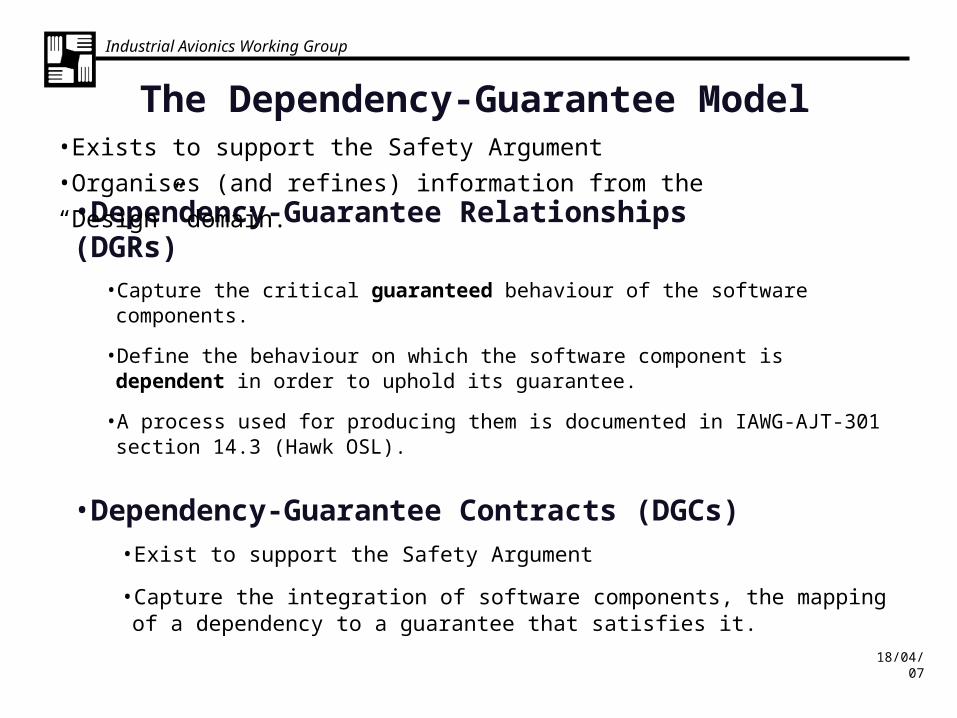
•Dependency-Guarantee Relationships (DGRs)• Capture the critical guaranteed behaviour of the software components.
• Define the behaviour on which the software component is dependent in order to uphold its guarantee.
• A process used for producing them is documented in IAWG-AJT-301 section 14.3 (Hawk OSL).
•Dependency-Guarantee Contracts (DGCs)• Exist to support the Safety Argument
• Capture the integration of software components, the mapping of a dependency to a guarantee that satisfies it.
•Exists to support the Safety Argument
•Organises (and refines) information from the “Design” domain.
The Dependency-Guarantee Model
Industrial Avionics Working Group
18/04/07
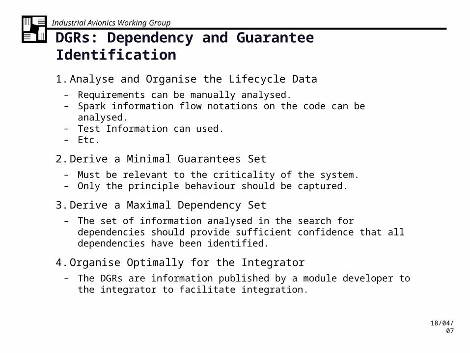
DGRs: Dependency and Guarantee Identification
1. Analyse and Organise the Lifecycle Data
– Requirements can be manually analysed.– Spark information flow notations on the code can be analysed.– Test Information can used.– Etc.
2. Derive a Minimal Guarantees Set
– Must be relevant to the criticality of the system.– Only the principle behaviour should be captured.
3. Derive a Maximal Dependency Set
– The set of information analysed in the search for dependencies should provide sufficient confidence that all dependencies have been identified.
4. Organise Optimally for the Integrator
– The DGRs are information published by a module developer to the integrator to facilitate integration.

Industrial Avionics Working Group
18/04/07
DGR Process 1: DGRs from Requirements Specifications
ORGANISING THE WORK
• Split the source material up into manageable groups. Define the PRIMITIVES. Each primitive is a candidate for a DGR.
(continued)
The quality and depth of requirements is quite variable from one project to another.
• Each PRIMITIVE should have a single purpose, a single guarantee. If there is a corresponding IFS that can be useful.
• PRIMITIVES should be reasonably independent, or is it a good design?
– Do sneak a peak at the design and IFS to get guidance if necessary.
– Choose PRIMITIVES that are as large as you can handle.

Industrial Avionics Working Group
18/04/07
DGR Process 2: DGRs from Requirements Specifications
ORGANISING THE WORK
(continued)
2. Group the primitives into modules.
(continued)
Choice of DGR modules is different from the choice of safety argument modules. (Several DGR modules may be utilised by the same safety argument).
Choose a DGR module for each software component. The configuration of DGR modules may be altered in the same way as the configuration of the system.
Again, Do sneak a peak at the design or other material to get guidance if necessary.

Industrial Avionics Working Group
18/04/07
ORGANISING THE WORK
(continued)
3. Identify the primitives whose behaviour is effective at the module boundary. (The external primitives)
4. Identify any hierarchy of primitives within the module.
(continued)
The external primitives may principally be the ones that correspond to the module services.
DGR Process 3: DGRs from Requirements Specifications

Industrial Avionics Working Group
18/04/07
DGR Process 4: Choice of Primitives
Module Boundary
subordinate Primitive
C
subordinate Primitive
D
subordinate Primitive
E
External Primitive
A
Data flow / functionality
change
External Primitive
B
Data flow / functionality
change
•Each primitive is just a group of requirements.

Industrial Avionics Working Group
18/04/07
(continued)
DOING THE WORK
5. Create DGR tables for the external primitives
6. Create DGR tables for the subordinate primitives
(continued)
DGR Process 5: DGRs from Requirements Specifications
See hints/tips on slides 12-17.
Industrial Avionics Working Group
18/04/07
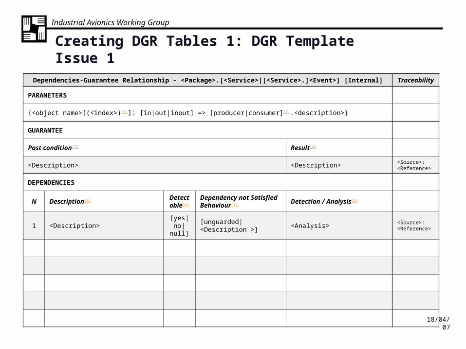
Dependencies-Guarantee Relationship – <Package>.[<Service>|[<Service>.]<Event>] [Internal] Traceability
PARAMETERS
{<object name>[(<index>)[1]]: [in|out|inout] => [producer|consumer][2].<description>}
GUARANTEE
Post condition[3] Result[4]
<Description> <Description><Source>: <Reference>
DEPENDENCIES
N Description[5] Detectable[6]
Dependency not Satisfied Behaviour[7] Detection / Analysis[8]
1 <Description>[yes|no|
null][unguarded|<Description >] <Analysis>
<Source>: <Reference>
Creating DGR Tables 1: DGR Template Issue 1

Industrial Avionics Working Group
18/04/07
Creating DGR Tables 1: Presentation Notes on DGR Template Issue 1
[1] The parameters provide a means of semi-formally identifying the information flows in/out of the primitive(s). Guarantees and Dependencies are expressed with reference to these information flows.[2] The transaction partner actual name will not be known, use keyword “consumer” or “producer”. [3] This is the english text description that will be used to satisfy a dependency. The requirement will be of the form something “shall” be done, the quarantee should state something “is” done. The formal postcondition from the code domain may be specified here (if the DGR is that detailed)? [4] This is a description of the values of any ‘control’ information that is passed out of the module when the guarantee is met. e.g. a returned status.[5] This is the description of the dependency from the source material domain in english text (with reference to parameters).[6] Can the absence or failure of the dependency be detected at run-time?[7] This is the postcondition if the dependency is detected as absent at run-time.[8] This is the information available for the formation of a contract to satisfy the dependency. It is called Detection/Analysis for historical reasons.

Industrial Avionics Working Group
18/04/07
Creating DGR Tables 2: Deriving the Guarantee
• The Guarantee
– Worded to assume the dependencies.
• It needs to be a guarantee that is useful to the argument.
– Concise
• But are all terms well defined? (e.g. “virtual channel”)
– Atomic.
• Could there be multiple DGRs here?
– Normal behaviour only.
• Guarantees to detect or handle errors are dealt with elsewhere.
– Guarantees can be supplied
• As a result of service calls
• As a result of events being serviced
• Upheld at all times.
Industrial Avionics Working Group
18/04/07
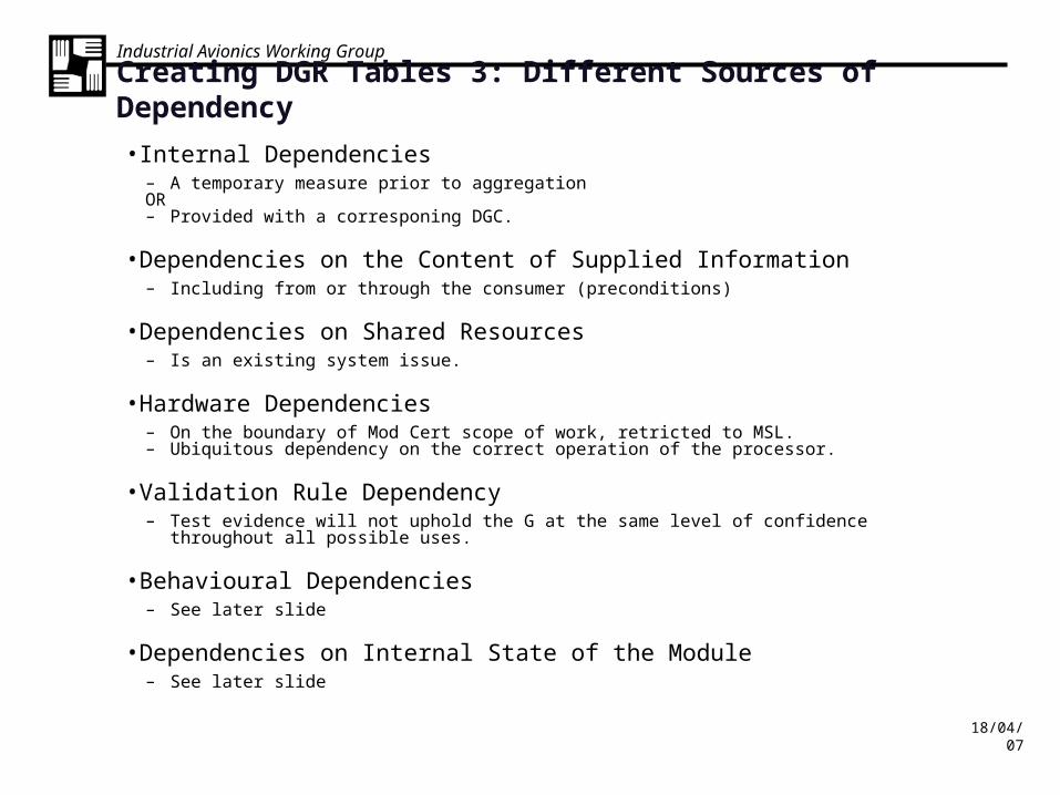
Creating DGR Tables 3: Different Sources of Dependency
• Internal Dependencies– A temporary measure prior to aggregation OR – Provided with a corresponing DGC.
• Dependencies on the Content of Supplied Information– Including from or through the consumer (preconditions)
• Dependencies on Shared Resources – Is an existing system issue.
• Hardware Dependencies– On the boundary of Mod Cert scope of work, retricted to MSL.– Ubiquitous dependency on the correct operation of the processor.
• Validation Rule Dependency– Test evidence will not uphold the G at the same level of confidence throughout all possible uses.
• Behavioural Dependencies– See later slide
• Dependencies on Internal State of the Module– See later slide

Industrial Avionics Working Group
18/04/07
Creating DGR Tables 4: Validation Rule Dependencies
This slide illustrates the thought process that might go on behind definition of a validation rule dependency.
Working at a well defined “single” level of confidence, what are the restrictions on the scope of the evidence set supporting the guarantee?
Multidimensional Input Parameter Space (from Specification)
Leve
l of C
onfid
ence
Evidence Set A(formal proof)
Evidence Set B(Requirements Traceability &
Coverage)
Certainty
Acceptable
Statisitically Neutral
Develo
pmen
t Life
cycle
Pha
se
Spe
cific
atio
n Des
ign
Impl
emen
tatio
n
Eviden
ce S
et D
(Vali
datio
n Tes
ts)
Evidence Set C(Preliminary
Hazard Analysis)

Industrial Avionics Working Group
18/04/07
• D1: The successful transmission of a request to module B• D2: The successful reception of an acknowledgement from module B• D3: The behaviour of module B, specifically that in response to the
reception of a request module B will send an acknowledge.
Creating DGR Tables 5: Behavioural Dependencies

Industrial Avionics Working Group
18/04/07
Creating DGR Tables 6: Dependencies on Internal State
• Common dilemma, but not one restricted to the DGR model.• Some Examples. In order to uphold the Guarantee…
• Some data in the Module must have been previously initialised.• Some data in the module must have been calculated from various
inputs.• The module must be in an appropriate state.
• These dependencies can be written temporarily as is and then refined later.• The developer should decide what is the minimal set of information about
the module’s internal state that he wishes to publish to its users and the DGRs should also stick to it.
Ease of Use Published Usage Model
simplest Services can be used in any sequence
simpler Service must be used in a defined sequence.
normal A System Mode Model is published to clarify definition of the call sequence, necessitating a system state variable.
more complex The published System Mode Model becomes modelled on multiple state variables.
most complex All the internal state data of the module must be published in order for its services to be used.

Industrial Avionics Working Group
18/04/07
The developer has decided that the minimal set of information about the module’s internal state that he wishes to publish to its users is a mode diagram. The DGRs may also refer to it.
Creating DGR Tables 7: Dependencies on Internal State
Initialising
Initialised
Normal
Configuring
Configured
Component Operation
Re-Configuration
Example Mode Diagram

Industrial Avionics Working Group
18/04/07
DOING THE WORK
(continued)
5. Either • Aggregate the subordinate DGR tables into the external DGR tables to
create the final DGRs.• This is an increasingly formal way of merging subordinate DGRs
into their parents.• Or
• Form DGCs to link them.• If the DGRs need to remain separate, e.g. if a service uses a sibling
service.
DGR Process 6: DGRs from Requirements Specifications
Aggregation is used to assist with the creation of DGRs for groups of source material that are too big to be handled as a single primitive.
See 5 following slides that animate aggregation.

Industrial Avionics Working Group
18/04/07
GuaranteeParameters
DGR A
Dependency A1Dependency A2.0Dependency A3
GuaranteeParameters
DGR B
Dependency B1Dependency B2Dependency B3
DGR Aggregation 1

Industrial Avionics Working Group
18/04/07
Guarantee
Parameters
DGR A
Dependency A1
Dependency A2.0
Dependency A3
Guarantee
Parameters
DGR B
Dependency B1
Dependency B2
Dependency B3
DGR Aggregation 2
Industrial Avionics Working Group
18/04/07
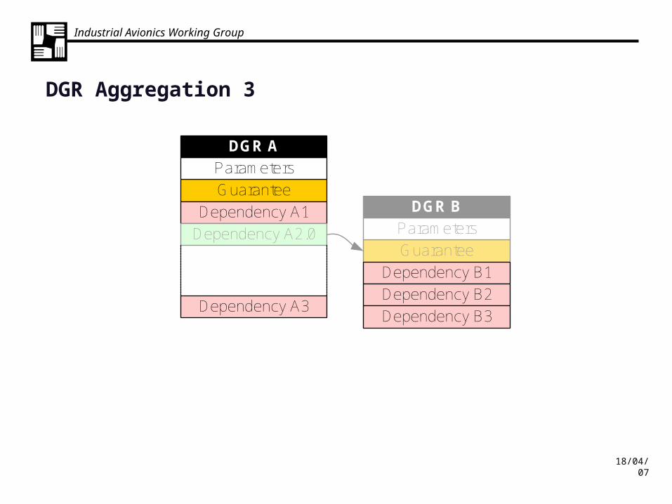
Guarantee
Parameters
DGR A
Dependency A1
Dependency A2.0
Dependency A3
Guarantee
Parameters
DGR B
Dependency B1
Dependency B2
Dependency B3
DGR Aggregation 3

Industrial Avionics Working Group
18/04/07
Guarantee
Parameters
DGR A
Dependency A1
Dependency A2.0
Dependency A3
Dependency B1
Dependency B2
Dependency B3
DGR Aggregation 4
Industrial Avionics Working Group
18/04/07
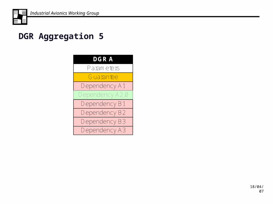
GuaranteeParameters
DGR A
Dependency A1Dependency A2.0
Dependency A3
Dependency B1Dependency B2Dependency B3
DGR Aggregation 5

Industrial Avionics Working Group
18/04/07
Guarantee
Parameters
DGR A
Dependency A1
Dependency A2.0
Dependency A3
Dependency A2.1
Dependency A2.2
Dependency A2.3
DGR Aggregation 6
Industrial Avionics Working Group
18/04/07
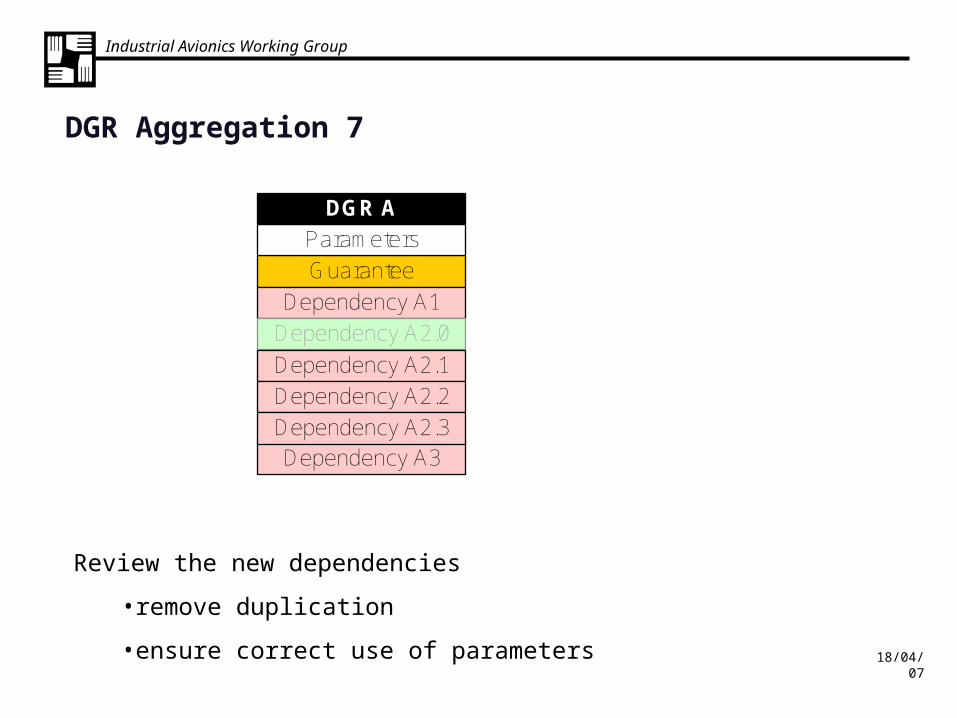
Guarantee
Parameters
DGR A
Dependency A1
Dependency A2.0
Dependency A3
Dependency A2.1
Dependency A2.2
Dependency A2.3
DGR Aggregation 7
Review the new dependencies
•remove duplication
•ensure correct use of parameters

Industrial Avionics Working Group
18/04/07
Summary of Presentation
• What is a DGRs (or DGCs)?
• How to create DGRs (from Requirements)– How to organising the work
• Primitives and DGR Modules– How to deal with commonly encountered issues
• Internal Dependencies• Dependencies on the Content of Supplied Information• Dependencies on Shared Resources • Hardware Dependencies• Validation Rule Dependency• Behavioural Dependencies• Dependencies on Internal State of the Module
• What is Aggregation?– When to use it.