Inductive proximity sensors - Farnell · PDF file3/20 Te 3 a b Accessories : page 3/59...
40
3/20 Te 3 a b Accessories : page 3/59 Inductive proximity sensors Cylindrical type, Ø 4 mm plain or M5 x 0.5 threaded Metal case (stainless steel), short d.c. supply References, characteristics, dimensions, schemes Flush mountable in metal Lengths (mm) : a = Overall a = 29 a = 41 b = Threaded or plain section b = 29 b = 24 Nominal sensing distance (Sn) 0.8 mm 0.8 mm References 3-wire a PNP NO XS1-L04PA311 XS1-L04PA311S NPN NO XS1-L04NA311 XS1-L04NA311S Weight (kg) 0.025 0.010 Characteristics Connection Pre-cabled, 3 x 0.11 mm 2 , length 2 m (1) Connector (types 1 to 8) (2) Depending on connector Degree of protection IP 67 (see pages 3/58 and 3/59) Operating temperature - 25…+ 70 °C Output state indication LED, side mounted Voltage limits (including ripple) a 5…30 V Switching capacity 0…100 mA with overload and short-circuit protection Voltage drop, closed state ≤ 2 V Current consumption, no-load ≤ 10 mA Maximum switching frequency 5000 Hz Wiring schemes 3-wire a, NO output (1) Sensors pre-cabled with other cable lengths : Length of cable Suffix to be added to references stated above for 2 m pre-cabled sensors Weight increase 5 m L1 0.030 kg 10 m L2 0.080 kg Example : sensor XS1-L04PA311 with 5 m cable becomes XS1-L04PA311L1 (2) The type numbers refer to suitable female connectors and extension cables, see pages 3/58 and 3/59. – BN/1 BU/3 + PNP BK/4 (NO) BK/2 (NC) BN/1 BU/3 + – BK/4 (NO) BK/2 (NC) NPN
Transcript of Inductive proximity sensors - Farnell · PDF file3/20 Te 3 a b Accessories : page 3/59...

3/20 Te
3
a
b
Accessories :page 3/59
Inductive proximity sensorsCylindrical type, Ø 4 mm plain or M5 x 0.5 threadedMetal case (stainless steel), shortd.c. supply
References, characteristics, dimensions, schemes
Flush mountable in metal
Lengths (mm) :a = Overall a = 29 a = 41b = Threaded or plain section b = 29 b = 24
Nominal sensing distance (Sn) 0.8 mm 0.8 mm
References
3-wire a PNP NO XS1-L04PA311 XS1-L04PA311S
NPN NO XS1-L04NA311 XS1-L04NA311S
Weight (kg) 0.025 0.010
Characteristics
Connection Pre-cabled, 3 x 0.11 mm 2, length 2 m (1) Connector (types 1 to 8) (2)Depending on connector
Degree of protection IP 67 (see pages 3/58 and 3/59)
Operating temperature - 25…+ 70 °C
Output state indication LED, side mounted
Voltage limits (including ripple) a 5…30 V
Switching capacity 0…100 mA with overload and short-circuit protection
Voltage drop, closed state ≤ 2 V
Current consumption, no-load ≤ 10 mA
Maximum switching frequency 5000 Hz
Wiring schemes
3-wire a, NO output
(1) Sensors pre-cabled with other cable lengths :Length of cable Suffix to be added to references stated above for 2 m pre-cabled sensors Weight increase5 m L1 0.030 kg10 m L2 0.080 kgExample : sensor XS1-L04PA311 with 5 m cable becomes XS1-L04PA311L1(2) The type numbers refer to suitable female connectors and extension cables, see pages 3/58 and 3/59.
–
BN/1
BU/3
+PNP BK/4 (NO)
BK/2 (NC)
BN/1
BU/3
+
–
BK/4 (NO)BK/2 (NC)
NPN

3/21Te
3
a = 45 a = 33 a = 42 a = 45b = 24 b = 27 b = 31 b = 21
c = 3 c = 3 c = 3
a = 29 a = 41b = 24 b = 24
0.8 mm 0.8 mm
XS1-N05PA311 XS1-N05PA311S
XS1-N05NA311 XS1-N05NA311S
0.030 0.015
Pre-cabled, 3 x 0.11 mm 2, length 2 m (1) Connector (types 1 to 8) (2)
IP 67 Depending on connector (see pages 3/58 and 3/59)
- 25…+ 70 °C
LED, side mounted
a 5…30 V
0…100 mA with overload and short-circuit protection
≤ 2 V
≤ 10 mA
5000 Hz
3/22 Te
3
a
b c
BN/1
BU/3
+
–WH/2 (NC)
NPNBK/4 (NO)
–
BN/1
BU/3
+PNP BK/4 (NO)
BK/2 (NC)
BN/1
BU/3
+
–WH/2 (NC)
PNP BK/4 (NO)
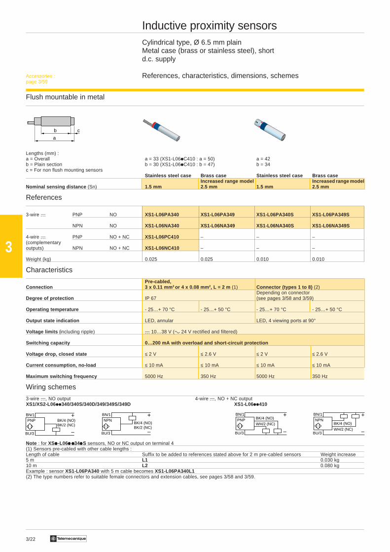
Inductive proximity sensorsCylindrical type, Ø 6.5 mm plainMetal case (brass or stainless steel), shortd.c. supply
References, characteristics, dimensions, schemes
Flush mountable in metal
Lengths (mm) :a = Overall a = 33 (XS1-L06iC410 : a = 50) a = 42b = Plain section b = 30 (XS1-L06iC410 : b = 47) b = 34c = For non flush mounting sensors
Stainless steel case Brass case Stainless steel case Brass caseIncreased range model Increased range model
Nominal sensing distance (Sn) 1.5 mm 2.5 mm 1.5 mm 2.5 mm
References
3-wire a PNP NO XS1-L06PA340 XS1-L06PA349 XS1-L06PA340S XS1-L06PA349S
NPN NO XS1-L06NA340 XS1-L06NA349 XS1-L06NA340S XS1-L06NA349S
4-wire a PNP NO + NC XS1-L06PC410 – – –(complementaryoutputs) NPN NO + NC XS1-L06NC410 – – –
Weight (kg) 0.025 0.025 0.010 0.010
Characteristics
Pre-cabled,Connection 3 x 0.11 mm 2 or 4 x 0.08 mm 2, L = 2 m (1) Connector (types 1 to 8) (2)
Depending on connectorDegree of protection IP 67 (see pages 3/58 and 3/59)
Operating temperature - 25…+ 70 °C - 25…+ 50 °C - 25…+ 70 °C - 25…+ 50 °C
Output state indication LED, annular LED, 4 viewing ports at 90°
Voltage limits (including ripple) a 10…38 V (c 24 V rectified and filtered)
Switching capacity 0…200 mA with overload and short-circuit protection
Voltage drop, closed state ≤ 2 V ≤ 2.6 V ≤ 2 V ≤ 2.6 V
Current consumption, no-load ≤ 10 mA ≤ 10 mA ≤ 10 mA ≤ 10 mA
Maximum switching frequency 5000 Hz 350 Hz 5000 Hz 350 Hz
Wiring schemes
3-wire a, NO output 4-wire a, NO + NC outputXS1/XS2-L06ii340/340S/340D/349/349S/349D XS1-L06ii410
Note : for XSiiiii -L06i ii ii ii ii i34iiiiiS sensors, NO or NC output on terminal 4(1) Sensors pre-cabled with other cable lengths :Length of cable Suffix to be added to references stated above for 2 m pre-cabled sensors Weight increase5 m L1 0.030 kg10 m L2 0.080 kgExample : sensor XS1-L06PA340 with 5 m cable becomes XS1-L06PA340L1(2) The type numbers refer to suitable female connectors and extension cables, see pages 3/58 and 3/59.
BN/1
BU/3
+
–
BK/4 (NO)BK/2 (NC)
NPN
Accessories :page 3/59
3/23Te
3
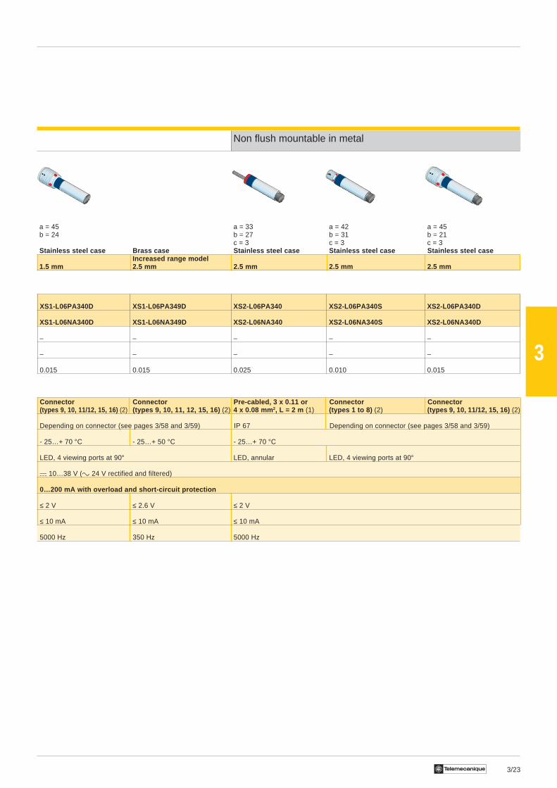
a = 45 a = 33 a = 42 a = 45b = 24 b = 27 b = 31 b = 21
c = 3 c = 3 c = 3
Non flush mountable in metal
a = 45 a = 33 a = 42 a = 45b = 24 b = 27 b = 31 b = 21
c = 3 c = 3 c = 3Stainless steel case Brass case Stainless steel case Stainless steel case Stainless steel case
Increased range model1.5 mm 2.5 mm 2.5 mm 2.5 mm 2.5 mm
XS1-L06PA340D XS1-L06PA349D XS2-L06PA340 XS2-L06PA340S XS2-L06PA340D
XS1-L06NA340D XS1-L06NA349D XS2-L06NA340 XS2-L06NA340S XS2-L06NA340D
– – – – –
– – – – –
0.015 0.015 0.025 0.010 0.015
Connector Connector Pre-cabled, 3 x 0.11 or Connector Connector(types 9, 10, 11/12, 15, 16) (2) (types 9, 10, 11, 12, 15, 16) (2) 4 x 0.08 mm 2, L = 2 m (1) (types 1 to 8) (2) (types 9, 10, 11/12, 15, 16) (2)
Depending on connector (see pages 3/58 and 3/59) IP 67 Depending on connector (see pages 3/58 and 3/59)
- 25…+ 70 °C - 25…+ 50 °C - 25…+ 70 °C
LED, 4 viewing ports at 90° LED, annular LED, 4 viewing ports at 90°
a 10…38 V (c 24 V rectified and filtered)
0…200 mA with overload and short-circuit protection
≤ 2 V ≤ 2.6 V ≤ 2 V
≤ 10 mA ≤ 10 mA ≤ 10 mA
5000 Hz 350 Hz 5000 Hz
3/24 Te
3
a
b c
–
BN/1
BU/3
+PNP BK/4 (NO)
BK/2 (NC)
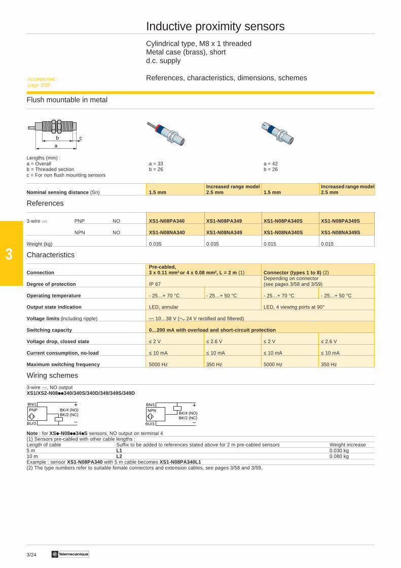
Inductive proximity sensorsCylindrical type, M8 x 1 threadedMetal case (brass), shortd.c. supply
References, characteristics, dimensions, schemes
Flush mountable in metal
Lengths (mm) :a = Overall a = 33 a = 42b = Threaded section b = 26 b = 26c = For non flush mounting sensors
Increased range model Increased range modelNominal sensing distance (Sn) 1.5 mm 2.5 mm 1.5 mm 2.5 mm
References
3-wire a PNP NO XS1-N08PA340 XS1-N08PA349 XS1-N08PA340S XS1-N08PA349S
NPN NO XS1-N08NA340 XS1-N08NA349 XS1-N08NA340S XS1-N08NA349S
Weight (kg) 0.035 0.035 0.015 0.015
Characteristics
Pre-cabled,Connection 3 x 0.11 mm 2 or 4 x 0.08 mm 2, L = 2 m (1) Connector (types 1 to 8) (2)
Depending on connectorDegree of protection IP 67 (see pages 3/58 and 3/59)
Operating temperature - 25…+ 70 °C - 25…+ 50 °C - 25…+ 70 °C - 25…+ 50 °C
Output state indication LED, annular LED, 4 viewing ports at 90°
Voltage limits (including ripple) a 10…38 V (c 24 V rectified and filtered)
Switching capacity 0…200 mA with overload and short-circuit protection
Voltage drop, closed state ≤ 2 V ≤ 2.6 V ≤ 2 V ≤ 2.6 V
Current consumption, no-load ≤ 10 mA ≤ 10 mA ≤ 10 mA ≤ 10 mA
Maximum switching frequency 5000 Hz 350 Hz 5000 Hz 350 Hz
Wiring schemes
3-wire a, NO outputXS1/XS2-N08ii340/340S/340D/349/349S/349D
Note : for XSi-N08ii34iS sensors, NO output on terminal 4(1) Sensors pre-cabled with other cable lengths :Length of cable Suffix to be added to references stated above for 2 m pre-cabled sensors Weight increase5 m L1 0.030 kg10 m L2 0.080 kgExample : sensor XS1-N08PA340 with 5 m cable becomes XS1-N08PA340L1(2) The type numbers refer to suitable female connectors and extension cables, see pages 3/58 and 3/59.
BN/1
BU/3
+
–
BK/4 (NO)BK/2 (NC)
NPN
Accessories :page 3/59
3/25Te
3
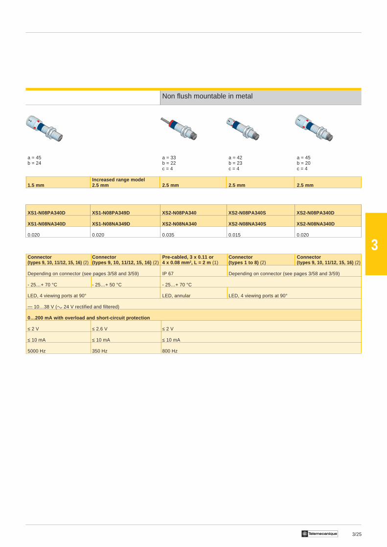
Non flush mountable in metal
a = 45 a = 33 a = 42 a = 45b = 24 b = 22 b = 23 b = 20
c = 4 c = 4 c = 4
Increased range model1.5 mm 2.5 mm 2.5 mm 2.5 mm 2.5 mm
XS1-N08PA340D XS1-N08PA349D XS2-N08PA340 XS2-N08PA340S XS2-N08PA340D
XS1-N08NA340D XS1-N08NA349D XS2-N08NA340 XS2-N08NA340S XS2-N08NA340D
0.020 0.020 0.035 0.015 0.020
Connector Connector Pre-cabled, 3 x 0.11 or Connector Connector(types 9, 10, 11/12, 15, 16) (2) (types 9, 10, 11/12, 15, 16) (2) 4 x 0.08 mm 2, L = 2 m (1) (types 1 to 8) (2) (types 9, 10, 11/12, 15, 16) (2)
Depending on connector (see pages 3/58 and 3/59) IP 67 Depending on connector (see pages 3/58 and 3/59)
- 25…+ 70 °C - 25…+ 50 °C - 25…+ 70 °C
LED, 4 viewing ports at 90° LED, annular LED, 4 viewing ports at 90°
a 10…38 V (c 24 V rectified and filtered)
0…200 mA with overload and short-circuit protection
≤ 2 V ≤ 2.6 V ≤ 2 V
≤ 10 mA ≤ 10 mA ≤ 10 mA
5000 Hz 350 Hz 800 Hz

3/26 Te
3
Inductive proximity sensorsCylindrical type, M8 x 1 threadedMetal case (stainless steel), form Ad.c. supply
References, characteristics, dimensions, schemes
Flush mountable in metal
Lengths (mm) :a = Overall a = 50 a = 61b = Threaded section b = 40 b = 40
Nominal sensing distance (Sn) 1.5 mm 1.5 mm
References
3-wire a PNP NO XS1-M08PA370 – XS1-M08PA370D –
NC XS1-M08PB370 – XS1-M08PB370D –
NPN NO XS1-M08NA370 – XS1-M08NA370D –2-wire a (non polarised)Supply to : Terminals 3-4 NO – – – –4-wire a (complementaryoutputs) PNP NO + NC – XS1-M08PC410 – XS1-M08PC410D
Weight (kg) 0.035 0.035 0.025 0.025
Characteristics
Connection Pre-cabled, 3 x 0.11 mm 2, length 2 m (1) Connector (types 9, 10, 11/12, 15, 16) (2)Depending on connector
Degree of protection IP 67 (see pages 3/58 and 3/59)
Operating temperature - 25…+ 80 °C
Output state indication LED annular LED, 4 viewing ports at 90°
Voltage limits (including ripple) a 10…58 V a 10…38 V a 10…58 V a 10…38 V
Switching capacity 0…200 mA with overload and short-circuit protection
Voltage drop, closed state ≤ 2 V
Current consumption, no-load ≤ 10 mA
Maximum switching frequency 5000 Hz
Wiring schemes
3-wire a, NO or NC output 2-wire a non polarised, NO output 4-wire a, NO + NC outputXS1-M08ii370/370D XS1-M08Di210/210D/210LD XS1-M08ii410/410D
(1) Sensors pre-cabled with other cable lengths:Length of cable Suffix to be added to references stated above for 2 m pre-cabled sensors Weight increase5 m L1 0.030 kg10 m L2 0.080 kgExample: sensor XS1-M08PA370 with 5 m cable becomes XS1-M08PA370L1(2) The type numbers refer to suitable female connectors and extension cables, see pages 3/58 and 3/59.
–
BN/1
BU/3
+PNP BK/4 (NO)
BK/2 (NC)
BN/1
BU/3
+
–
BK/4 (NO)BK/2 (NC)
NPNBN/3
BU/4
+/–
–/+NO
BN/1
BN/1
BU/2
+/–
–/+NC
BN/1
BU/3
+
–WH/2 (NC)
PNP BK/4 (NO)BN/1
BU/3
+
–WH/2 (NC)
NPNBK/4 (NO)
Accessories:page 3/59
a
b
3/27Te
3
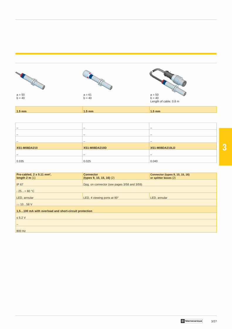
a = 50 a = 61 a = 50b = 40 b = 40 b = 40
Length of cable: 0.8 m
1.5 mm 1.5 mm 1.5 mm
– – –
– – –
– – –
XS1-M08DA210 XS1-M08DA210D XS1-M08DA210LD
– – –
0.035 0.025 0.040
Pre-cabled, 2 x 0.11 mm 2, Connector Connector (types 9, 10, 15, 16)length 2 m (1) (types 9, 10, 15, 16) (2) or splitter boxes (2)
IP 67 Dpg. on connector (see pages 3/58 and 3/59)
- 25…+ 80 °C
LED, annular LED, 4 viewing ports at 90° LED, annular
a 10…58 V
1,5…100 mA with overload and short-circuit protection
≤ 5.2 V
–
800 Hz

3/28 Te
3
a
b c
BN/2
BU/3
Inductive proximity sensorsCylindrical type, M8 x 1 threadedMetal case (stainless steel), form Aa.c. or d.c. supply
References, characteristics, dimensions, schemes
Flush mountable in metal
Lengths (mm) :a = Overall a = 50b = Threaded section b = 40c = For non flush mounting sensors
Nominal sensing distance (Sn) 1.5 mm
References
2-wire c or a NO XS1-M08MA230
NC XS1-M08MB230
Weight (kg) 0.035
Characteristics
Connection Pre-cabled, 2 x 0.11 mm 2, length 2 m (1)
Degree of protection IP 67
Operating temperature - 25…+ 80 °C
Output state indication LED, annular
Voltage limits (including ripple) c or a 20…264 V
Switching capacity 5…100 mA (2)
Voltage drop, closed state ≤ 5.5 V
Current consumption, no-load –
Maximum switching frequency (c) 25 Hz or (a) 650 Hz
Wiring schemes
2-wire c or a, NO or NC output
For connector version sensors(1) Sensors pre-cabled with other cable lengths :Length of cable Suffix to be added to references stated above for 2 m pre-cabled sensors Weight increase5 m L1 0.030 kg10 m L2 0.080 kgExample : sensor XS1-M08MA230 with 5 m cable becomes XS1-M08MA230L1(2) These sensors do not incorporate overload or short-circuit protection and therefore, it is recommended that a 0.8 A “quick-blow” fuse be connected in serieswith the load.
Accessories :page 3/59
3/29Te
3
a = 45 a = 33 a = 42 a = 45b = 24 b = 27 b = 31 b = 21
c = 3 c = 3 c = 3
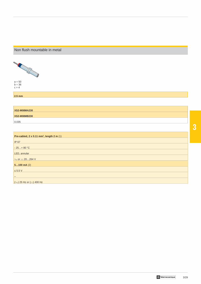
Non flush mountable in metal
a = 50b = 36c = 4
2.5 mm
XS2-M08MA230
XS2-M08MB230
0.035
Pre-cabled, 2 x 0.11 mm 2, length 2 m (1)
IP 67
- 25…+ 80 °C
LED, annular
c or a 20…264 V
5…100 mA (2)
≤ 5.5 V
–
(c) 25 Hz or (a) 400 Hz
3/30 Te
3
a
b c
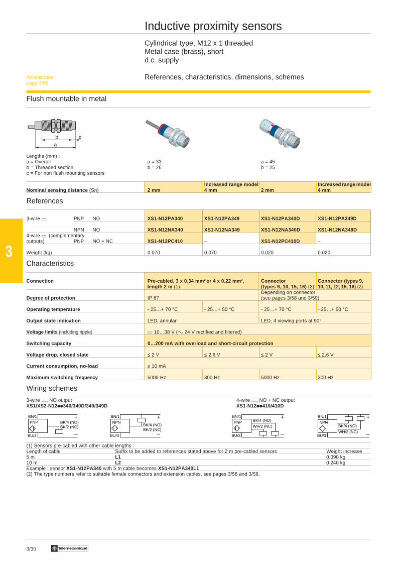
Inductive proximity sensorsCylindrical type, M12 x 1 threadedMetal case (brass), shortd.c. supply
References, characteristics, dimensions, schemes
Flush mountable in metal
Lengths (mm) :a = Overall a = 33 a = 45b = Threaded section b = 26 b = 25c = For non flush mounting sensors
Increased range model Increased range modelNominal sensing distance (Sn) 2 mm 4 mm 2 mm 4 mm
References
3-wire a PNP NO XS1-N12PA340 XS1-N12PA349 XS1-N12PA340D XS1-N12PA349D
NPN NO XS1-N12NA340 XS1-N12NA349 XS1-N12NA340D XS1-N12NA349D4-wire a (complementaryoutputs) PNP NO + NC XS1-N12PC410 – XS1-N12PC410D –
Weight (kg) 0.070 0.070 0.020 0.020
Characteristics
Connection Pre-cabled, 3 x 0.34 mm 2 or 4 x 0.22 mm 2, Connector Connector (types 9,length 2 m (1) (types 9, 10, 15, 16) (2) 10, 11, 12, 15, 16) (2)
Depending on connectorDegree of protection IP 67 (see pages 3/58 and 3/59)
Operating temperature - 25…+ 70 °C - 25…+ 50 °C - 25…+ 70 °C - 25…+ 50 °C
Output state indication LED, annular LED, 4 viewing ports at 90°
Voltage limits (including ripple) a 10…38 V (c 24 V rectified and filtered)
Switching capacity 0…200 mA with overload and short-circuit protection
Voltage drop, closed state ≤ 2 V ≤ 2.6 V ≤ 2 V ≤ 2.6 V
Current consumption, no-load ≤ 10 mA
Maximum switching fre quency 5000 Hz 300 Hz 5000 Hz 300 Hz
Wiring schemes
3-wire a, NO output 4-wire a, NO + NC outputXS1/XS2-N12ii340/340D/349/349D XS1-N12ii410/410D
(1) Sensors pre-cabled with other cable lengths :Length of cable Suffix to be added to references stated above for 2 m pre-cabled sensors Weight increase5 m L1 0.090 kg10 m L2 0.240 kgExample : sensor XS1-N12PA340 with 5 m cable becomes XS1-N12PA340L1(2) The type numbers refer to suitable female connectors and extension cables, see pages 3/58 and 3/59.
–
BN/1
BU/3
+PNP BK/4 (NO)
BK/2 (NC)
BN/1
BU/3
+
–
BK/4 (NO)BK/2 (NC)
NPN
BN/1
BU/3
+
–WH/2 (NC)
PNP BK/4 (NO)BN/1
BU/3
+
–WH/2 (NC)
NPNBK/4 (NO)
Accessories :page 3/59

3/31Te
3
Non flush mountable in metal
a = 33 a = 45b = 21 b = 20c = 5 c = 5
4 mm 4 mm
XS2-N12PA340 XS2-N12PA340D
XS2-N12NA340 XS2-N12NA340D
– –
0.070 0.020
Pre-cabled, 3 x 0.34 mm 2 or 4 x 0.22 mm 2, length 2 m (1) Connector (types 9, 10, 15, 16) (2)
IP 67 Depending on connector (see pages 3/58 and 3/59)
- 25…+ 70 °C
LED, annular LED, 4 viewing ports at 90°
a 10…38 V (c 24 V rectified and filtered)
0…200 mA with overload and short-circuit protection
≤ 2 V
≤ 10 mA
5000 Hz
3/32 Te
3
a
b c
BN/1
BU/3
+
–
BK/4 (NO)BK/2 (NC)
NPN
–
BN/1
BU/3
+PNP BK/4 (NO)
BK/2 (NC)
BU/3 (NO), BN/1 (NC)
+
BK/4PNP
–
BN/1 (NO), BU/3 (NC)
WH/2 +
–
WH/2NPN
BN/1 (NO), BU/3 (NC)
BU/3 (NO), BN/1 (NC)
BK/4
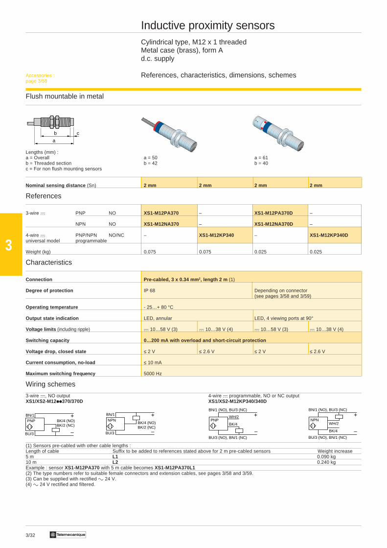
Inductive proximity sensorsCylindrical type, M12 x 1 threadedMetal case (brass), form Ad.c. supply
References, characteristics, dimensions, schemes
Flush mountable in metal
Lengths (mm) :a = Overall a = 50 a = 61b = Threaded section b = 42 b = 40c = For non flush mounting sensors
Nominal sensing distance (Sn) 2 mm 2 mm 2 mm 2 mm
References
3-wire a PNP NO XS1-M12PA370 – XS1-M12PA370D –
NPN NO XS1-M12NA370 – XS1-M12NA370D –
4-wire a PNP/NPN NO/NC – XS1-M12KP340 – XS1-M12KP340Duniversal model programmable
Weight (kg) 0.075 0.075 0.025 0.025
Characteristics
Connection Pre-cabled, 3 x 0.34 mm 2, length 2 m (1)
Degree of protection IP 68 Depending on connector(see pages 3/58 and 3/59)
Operating temperature - 25…+ 80 °C
Output state indication LED, annular LED, 4 viewing ports at 90°
Voltage limits (including ripple) a 10…58 V (3) a 10…38 V (4) a 10…58 V (3) a 10…38 V (4)
Switching capacity 0…200 mA with overload and short-circuit protection
Voltage drop, closed state ≤ 2 V ≤ 2.6 V ≤ 2 V ≤ 2.6 V
Current consumption, no-load ≤ 10 mA
Maximum switching fre quency 5000 Hz
Wiring schemes
3-wire a, NO output 4-wire a programmable, NO or NC outputXS1/XS2-M12ii370/370D XS1/XS2-M12KP340/340D
(1) Sensors pre-cabled with other cable lengths :Length of cable Suffix to be added to references stated above for 2 m pre-cabled sensors Weight increase5 m L1 0.090 kg10 m L2 0.240 kgExample : sensor XS1-M12PA370 with 5 m cable becomes XS1-M12PA370L1(2) The type numbers refer to suitable female connectors and extension cables, see pages 3/58 and 3/59.(3) Can be supplied with rectified c 24 V.(4) c 24 V rectified and filtered.
Accessories :page 3/59

3/33Te
3
Non flush mountable in metal
a = 50 a = 61b = 37 b = 35c = 5 c = 5
4 mm 4 mm 4 mm 4 mm
XS2-M12PA370 – XS2-M12PA370D –
XS2-M12NA370 – XS2-M12NA370D
– XS2-M12KP340 – XS2-M12KP340D
0.075 0.075 0.025 0.075
Pre-cabled, 3 x 0.34 mm 2, length 2 m (1) Connector (types 9, 10, 15, 16) (2)
IP 68 Depending on connector(see pages 3/58 and 3/59)
- 25…+ 80 °C
LED, annular LED, 4 viewing ports at 90°
a 10…58 V (3) a 10…38 V (4) a 10…58 V (3) a 10…38 V (4)
0…200 mA with overload and short-circuit protection
≤ 2 V ≤ 2.6 V ≤ 2 V ≤ 2.6 V
≤ 10 mA
5000 Hz
3/34 Te
3
a
b
BN/3
BU/4
+/–
–/+NO
BN/1BN/1
BU/2
+/–
–/+NC
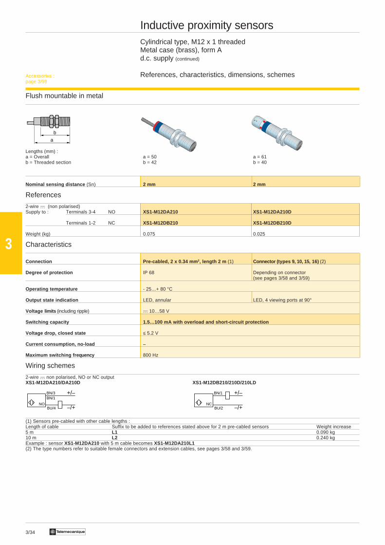
Inductive proximity sensorsCylindrical type, M12 x 1 threadedMetal case (brass), form Ad.c. supply (continued)
References, characteristics, dimensions, schemes
Flush mountable in metal
Lengths (mm) :a = Overall a = 50 a = 61b = Threaded section b = 42 b = 40
Nominal sensing distance (Sn) 2 mm 2 mm
References
2-wire a (non polarised)Supply to : Terminals 3-4 NO XS1-M12DA210 XS1-M12DA210D
Terminals 1-2 NC XS1-M12DB210 XS1-M12DB210D
Weight (kg) 0.075 0.025
Characteristics
Connection Pre-cabled, 2 x 0.34 mm 2, length 2 m (1) Connector ( types 9, 10, 15, 16) (2)
Degree of protection IP 68 Depending on connector(see pages 3/58 and 3/59)
Operating temperature - 25…+ 80 °C
Output state indication LED, annular LED, 4 viewing ports at 90°
Voltage limits (including ripple) a 10…58 V
Switching capacity 1.5…100 mA with overload and short-circuit protection
Voltage drop, closed state ≤ 5.2 V
Current consumption, no-load –
Maximum switching freq uency 800 Hz
Wiring schemes
2-wire a non polarised, NO or NC outputXS1-M12DA210/DA210D XS1-M12DB210/210D/210LD
(1) Sensors pre-cabled with other cable lengths :Length of cable Suffix to be added to references stated above for 2 m pre-cabled sensors Weight increase5 m L1 0.090 kg10 m L2 0.240 kgExample : sensor XS1-M12DA210 with 5 m cable becomes XS1-M12DA210L1(2) The type numbers refer to suitable female connectors and extension cables, see pages 3/58 and 3/59.
Accessories :page 3/59
3/35Te
3
a
b c
BN/2
BU/3
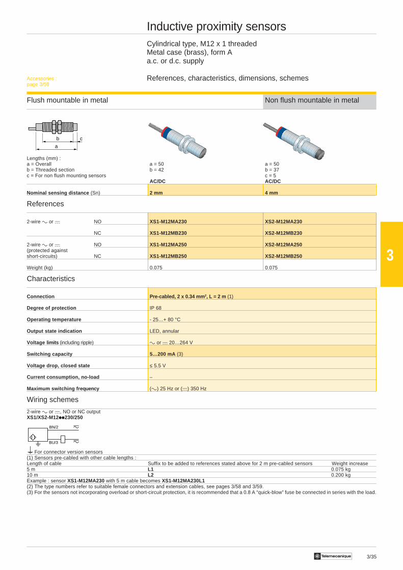
Inductive proximity sensorsCylindrical type, M12 x 1 threadedMetal case (brass), form Aa.c. or d.c. supply
References, characteristics, dimensions, schemes
Flush mountable in metal Non flush mountable in metal
Lengths (mm) :a = Overall a = 50 a = 50b = Threaded section b = 42 b = 37c = For non flush mounting sensors c = 5
AC/DC AC/DC
Nominal sensing distance (Sn) 2 mm 4 mm
References
2-wire c or a NO XS1-M12MA230 XS2-M12MA230
NC XS1-M12MB230 XS2-M12MB230
2-wire c or a NO XS1-M12MA250 XS2-M12MA250(protected againstshort-circuits) NC XS1-M12MB250 XS2-M12MB250
Weight (kg) 0.075 0.075
Characteristics
Connection Pre-cabled, 2 x 0.34 mm 2, L = 2 m (1)
Degree of protection IP 68
Operating temperature - 25…+ 80 °C
Output state indication LED, annular
Voltage limits (including ripple) c or a 20…264 V
Switching capacity 5…200 mA (3)
Voltage drop, closed state ≤ 5.5 V
Current consumption, no-load –
Maximum switching fre quency (c) 25 Hz or (a) 350 Hz
Wiring schemes
2-wire c or a, NO or NC outputXS1/XS2-M12ii230/250
For connector version sensors(1) Sensors pre-cabled with other cable lengths :Length of cable Suffix to be added to references stated above for 2 m pre-cabled sensors Weight increase5 m L1 0.075 kg10 m L2 0.200 kgExample : sensor XS1-M12MA230 with 5 m cable becomes XS1-M12MA230L1(2) The type numbers refer to suitable female connectors and extension cables, see pages 3/58 and 3/59.(3) For the sensors not incorporating overload or short-circuit protection, it is recommended that a 0.8 A “quick-blow” fuse be connected in series with the load.
Accessories :page 3/59

3/36 Te
3
a
b c
–
BN/1
BU/3
+PNP BK/4 (NO)
BK/2 (NC)
BN/1
BU/3
+
–
BK/4 (NO)BK/2 (NC)
NPN
BN/1
BU/3
+
–WH/2 (NC)
PNP BK/4 (NO)BN/1
BU/3
+
–WH/2 (NC)
NPNBK/4 (NO)
Inductive proximity sensorsCylindrical type, M18 x 1 threadedMetal case (brass), shortd.c. supply
References, characteristics, dimensions, schemes
Flush mountable in metal
Lengths (mm) :a = Overall a = 33.5 a = 45b = Threaded section b = 26 b = 26c = For non flush mounting sensors
Increased range model Increased range modelNominal sensing distance (Sn) 5 mm 10 mm 5 mm 10 mm
References
3-wire a PNP NO XS1-N18PA340 XS1-N18PA349 XS1-N18PA340D XS1-N18PA349D
NPN NO XS1-N18NA340 XS1-N18NA349 XS1-N18NA340D XS1-N18NA349D
4-wire a PNP NO + NC XS1-N18PC410 – XS1-N18PC410D –(complementaryoutputs) NPN NO + NC XS1-N18NC410 – XS1-N18NC410D –
Weight (kg) 0.100 0.100 0.040 0.040
Characteristics
Pre-cabled, 3 x 0.34 mm 2 or 4 x 0.34 mm 2, Connector Connector (types 9,Connection length 2 m (1) (types 9, 10, 15, 16) (2) 10, 11, 12, 15, 16) (2)
Depending on connectorDegree of protection IP 67 (see pages 3/58 and 3/59)
Operating temperature - 25…+ 70 °C - 25…+ 50 °C - 25…+ 70 °C - 25…+ 50 °C
Output state indication LED, annular LED, 4 viewing ports at 90°
Voltage limits (including ripple) a 10…38 V (c 24 V rectified and filtered)
Switching capacity 0…200 mA with overload and short-circuit protection
Voltage drop, closed state ≤ 2 V ≤ 2.6 V ≤ 2 V ≤ 2.6 V
Current consumption, no-load ≤ 10 mA
Maximum switching fre quency 2000 Hz 60 Hz 2000 Hz 60 Hz
Wiring schemes
3-wire a, NO output 4-wire a, NO + NC outputXS1/XS2-N18ii340/340D/349/349D XS1/XS2-N18ii410/410D
(1) Sensors pre-cabled with other cable lengths :Length of cable Suffix to be added to references stated above for 2 m pre-cabled sensors Weight increase5 m L1 0.120 kg10 m L2 0.320 kgExample : sensor XS1-N18PA340 with 5 m cable becomes XS1-N18PA340L1(2) The type numbers refer to suitable female connectors and extension cables, see pages 3/58 and 3/59.
Accessories :page 3/59
3/37Te
3
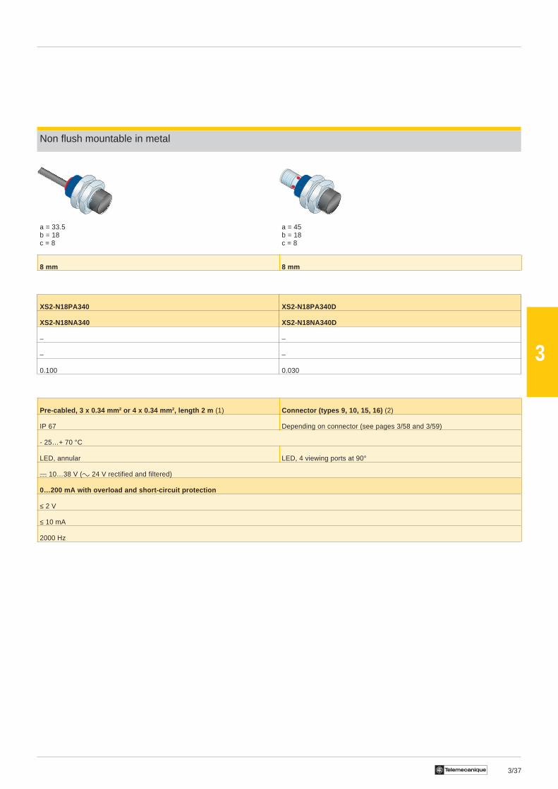
Non flush mountable in metal
a = 33.5 a = 45b = 18 b = 18c = 8 c = 8
8 mm 8 mm
XS2-N18PA340 XS2-N18PA340D
XS2-N18NA340 XS2-N18NA340D
– –
– –
0.100 0.030
Pre-cabled, 3 x 0.34 mm 2 or 4 x 0.34 mm 2, length 2 m (1) Connector (types 9, 10, 15, 16) (2)
IP 67 Depending on connector (see pages 3/58 and 3/59)
- 25…+ 70 °C
LED, annular LED, 4 viewing ports at 90°
a 10…38 V (c 24 V rectified and filtered)
0…200 mA with overload and short-circuit protection
≤ 2 V
≤ 10 mA
2000 Hz

3/38 Te
3
a
b
BU/3 (NO), BN/1 (NC)
+
BK/4PNP
–
BN/1 (NO), BU/3 (NC)
WH/2 +
–
WH/2NPN
BN/1 (NO), BU/3 (NC)
BU/3 (NO), BN/1 (NC)
BK/4–
BN/1
BU/3
+PNP BK/4 (NO)
BK/2 (NC)
BN/1
BU/3
+
–
BK/4 (NO)BK/2 (NC)
NPN
Inductive proximity sensorsCylindrical type, M18 x 1 threadedMetal case (brass), form Ad.c. supply
References, characteristics, dimensions, schemes
Flush mountable in metal
Lengths (mm) :a = Overall a = 60 a = 70b = Threaded section b = 51.5 b = 51.5
Nominal sensing distance (Sn) 5 mm 5 mm 5 mm 5 mm
References
3-wire a PNP NO XS1-M18PA370 – XS1-M18PA370D –
NPN NO XS1-M18NA370 – XS1-M18NA370D –
4-wire a PNP/NPN NO/NC – XS1-M18KP340 – XS1-M18KP340Duniversal model programmable
Weight (kg) 0.120 0.120 0.060 0.060
Characteristics
Connection Pre-cabled, 3 x 0.34 mm 2, length 2 m (1) Connector (types 9, 10, 15, 16) (2)Depending on connector
Degree of protection IP 68 (see pages 3/58 and 3/59)
Operating temperature - 25…+ 80 °C
Output state indication LED, annular LED, 4 viewing ports at 90°
Voltage limits (including ripple) a 10…58 V (3) a 10…38 V (4) a 10…58 V (3) a 10…38 V (4)
Switching capacity 0…200 mA with overload and short-circuit protection
Voltage drop, closed state ≤ 2 V ≤ 2.6 V ≤ 2 V ≤ 2.6 V
Current consumption, no-load ≤ 10 mA
Maximum switching fre quency 2000 Hz
Wiring schemes
3-wire a, NO output 4-wire a programmable, NO or NC outputXS1-M18ii370/370D XS1-M18KP340/340D
(1) Sensors pre-cabled with other cable lengths :Length of cable Suffix to be added to references stated above for 2 m pre-cabled sensors Weight increase5 m L1 0.120 kg10 m L2 0.320 kgExample : sensor XS1-M18PA370 with 5 m cable becomes XS1-M18PA370L1(2) The type numbers refer to suitable female connectors and extension cables, see pages 3/58 and 3/59.(3) Can be supplied with rectified c 24 V.(4) c 24 V rectified and filtered.
Accessories :page 3/59
3/39Te
3
a
b c
BN/1
BU/3
+
–
BK/4 (NO)BK/2 (NC)
NPN
–
BN/1
BU/3
+PNP BK/4 (NO)
BK/2 (NC)
BU/3 (NO), BN/1 (NC)
+
BK/4PNP
–
BN/1 (NO), BU/3 (NC)
WH/2
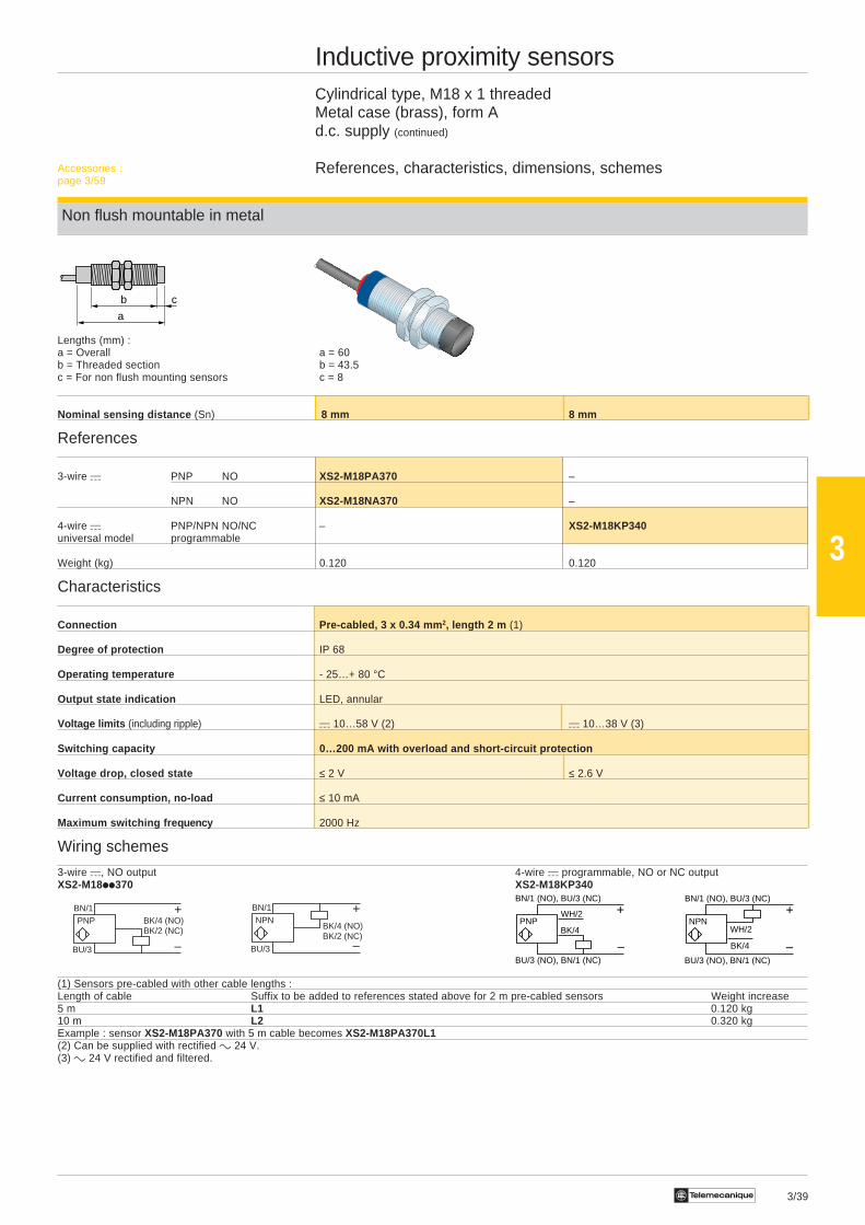
Inductive proximity sensorsCylindrical type, M18 x 1 threadedMetal case (brass), form Ad.c. supply (continued)
References, characteristics, dimensions, schemes
Non flush mountable in metal
Lengths (mm) :a = Overall a = 60b = Threaded section b = 43.5c = For non flush mounting sensors c = 8
Nominal sensing distance (Sn) 8 mm 8 mm
References
3-wire a PNP NO XS2-M18PA370 –
NPN NO XS2-M18NA370 –
4-wire a PNP/NPN NO/NC – XS2-M18KP340universal model programmable
Weight (kg) 0.120 0.120
Characteristics
Connection Pre-cabled, 3 x 0.34 mm 2, length 2 m (1)
Degree of protection IP 68
Operating temperature - 25…+ 80 °C
Output state indication LED, annular
Voltage limits (including ripple) a 10…58 V (2) a 10…38 V (3)
Switching capacity 0…200 mA with overload and short-circuit protection
Voltage drop, closed state ≤ 2 V ≤ 2.6 V
Current consumption, no-load ≤ 10 mA
Maximum switching fre quency 2000 Hz
Wiring schemes
3-wire a, NO output 4-wire a programmable, NO or NC outputXS2-M18ii370 XS2-M18KP340
(1) Sensors pre-cabled with other cable lengths :Length of cable Suffix to be added to references stated above for 2 m pre-cabled sensors Weight increase5 m L1 0.120 kg10 m L2 0.320 kgExample : sensor XS2-M18PA370 with 5 m cable becomes XS2-M18PA370L1(2) Can be supplied with rectified c 24 V.(3) c 24 V rectified and filtered.
Accessories :page 3/59
+
–
WH/2NPN
BN/1 (NO), BU/3 (NC)
BU/3 (NO), BN/1 (NC)
BK/4
3/40 Te
3
a
b
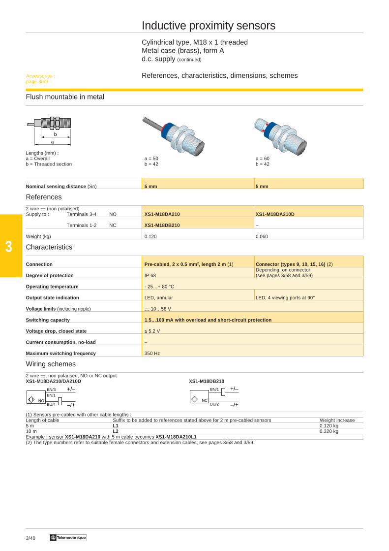
Inductive proximity sensorsCylindrical type, M18 x 1 threadedMetal case (brass), form Ad.c. supply (continued)
References, characteristics, dimensions, schemes
Flush mountable in metal
Lengths (mm) :a = Overall a = 50 a = 60b = Threaded section b = 42 b = 42
Nominal sensing distance (Sn) 5 mm 5 mm
References
2-wire a (non polarised)Supply to : Terminals 3-4 NO XS1-M18DA210 XS1-M18DA210D
Terminals 1-2 NC XS1-M18DB210 –
Weight (kg) 0.120 0.060
Characteristics
Connection Pre-cabled, 2 x 0.5 mm 2, length 2 m (1) Connector (types 9, 10, 15, 16) (2)Depending. on connector
Degree of protection IP 68 (see pages 3/58 and 3/59)
Operating temperature - 25…+ 80 °C
Output state indication LED, annular LED, 4 viewing ports at 90°
Voltage limits (including ripple) a 10…58 V
Switching capacity 1.5…100 mA with overload and short-circuit protection
Voltage drop, closed state ≤ 5.2 V
Current consumption, no-load –
Maximum switching fre quency 350 Hz
Wiring schemes
2-wire a, non polarised, NO or NC outputXS1-M18DA210/DA210D XS1-M18DB210
(1) Sensors pre-cabled with other cable lengths :Length of cable Suffix to be added to references stated above for 2 m pre-cabled sensors Weight increase5 m L1 0.120 kg10 m L2 0.320 kgExample : sensor XS1-M18DA210 with 5 m cable becomes XS1-M18DA210L1(2) The type numbers refer to suitable female connectors and extension cables, see pages 3/58 and 3/59.
BN/3
BU/4
+/–
–/+NO
BN/1
BN/1
BU/2
+/–
–/+NC
Accessories :page 3/59
3/41Te
3
a
b
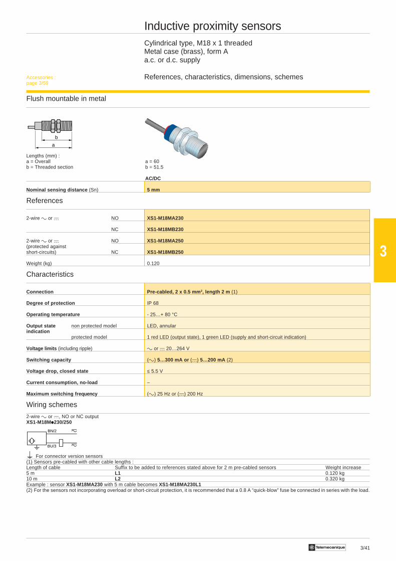
Inductive proximity sensorsCylindrical type, M18 x 1 threadedMetal case (brass), form Aa.c. or d.c. supply
References, characteristics, dimensions, schemes
Flush mountable in metal
Lengths (mm) :a = Overall a = 60b = Threaded section b = 51.5
AC/DC
Nominal sensing distance (Sn) 5 mm
References
2-wire c or a NO XS1-M18MA230
NC XS1-M18MB230
2-wire c or a NO XS1-M18MA250(protected againstshort-circuits) NC XS1-M18MB250
Weight (kg) 0.120
Characteristics
Connection Pre-cabled, 2 x 0.5 mm 2, length 2 m (1)
Degree of protection IP 68
Operating temperature - 25…+ 80 °C
Output state non protected model LED, annularindication
protected model 1 red LED (output state), 1 green LED (supply and short-circuit indication)
Voltage limits (including ripple) c or a 20…264 V
Switching capacity (c) 5…300 mA or (a) 5…200 mA (2)
Voltage drop, closed state ≤ 5.5 V
Current consumption, no-load –
Maximum switching fre quency (c) 25 Hz or (a) 200 Hz
Wiring schemes
2-wire c or a, NO or NC outputXS1-M18Mi230/250
For connector version sensors(1) Sensors pre-cabled with other cable lengths :Length of cable Suffix to be added to references stated above for 2 m pre-cabled sensors Weight increase5 m L1 0.120 kg10 m L2 0.320 kgExample : sensor XS1-M18MA230 with 5 m cable becomes XS1-M18MA230L1(2) For the sensors not incorporating overload or short-circuit protection, it is recommended that a 0.8 A “quick-blow” fuse be connected in series with the load.
BN/2
BU/3
Accessories :page 3/59
3/42 Te
3
a
b c
–
BN/1
BU/3
+PNP BK/4 (NO)
BK/2 (NC)
BN/1
BU/3
+
–
BK/4 (NO)BK/2 (NC)
NPN
Inductive proximity sensorsCylindrical type, M30 x 1.5 threadedMetal case (brass), shortd.c. supply
References, characteristics, dimensions, schemes
Flush mountable in metal
Lengths (mm) :a = Overall a = 40.5 a = 50b = Threaded section b = 32 b = 30c = For non flush mounting sensors
Increased range model Increased range modelNominal sensing distance (Sn) 10 mm 20 mm 10 mm 20 mm
References
3-wire a PNP NO XS1-N30PA340 XS1-N30PA349 XS1-N30PA340D XS1-N30PA349D
NPN NO XS1-N30NA340 XS1-N30NA349 XS1-N30NA340D XS1-N30NA349D
Weight (kg) 0.160 0.160 0.100 0.100
Characteristics
Connector Connector (types 9,Connection Pre-cabled, 3 or 4 x 0.34 mm 2, length 2 m (1) (types 9, 10, 15, 16) (2) 10, 11/12, 15, 16) (2)
Depending on connectorDegree of protection IP 67 (see pages 3/58 and 3/59)
Operating temperature - 25…+ 70 °C - 25…+ 50 °C - 25…+ 70 °C - 25…+ 50 °C
Output state indication LED, annular LED, 4 viewing ports at 90°
Voltage limits (including ripple) a 10…38 V (c 24 V rectified and filtered)
Switching capacity 0…200 mA with overload and short-circuit protection
Voltage drop, closed state ≤ 2 V ≤ 2.6 V ≤ 2 V ≤ 2.6 V
Current consumption, no-load ≤ 10 mA
Maximum switching fre quency 1000 Hz 15 Hz 1000 Hz 15 Hz
Wiring schemes
3-wire a, NO outputXS1/XS2-N30i340/340D/349/349D
(1) Sensors pre-cabled with other cable lengths :Length of cable Suffix to be added to references stated above for 2 m pre-cabled sensors Weight increase5 m L1 0.120 kg10 m L2 0.320 kgExample : sensor XS1-N30PA340 with 5 m cable becomes XS1-N30PA340L1(2) The type numbers refer to suitable female connectors and extension cables, see pages 3/58 and 3/59.
Accessories :page 3/59
3/43Te
3
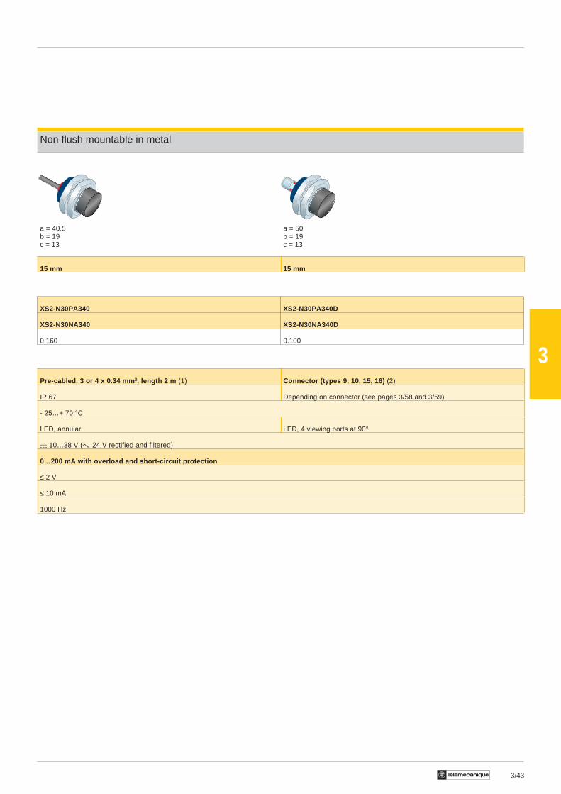
Non flush mountable in metal
a = 40.5 a = 50b = 19 b = 19c = 13 c = 13
15 mm 15 mm
XS2-N30PA340 XS2-N30PA340D
XS2-N30NA340 XS2-N30NA340D
0.160 0.100
Pre-cabled, 3 or 4 x 0.34 mm 2, length 2 m (1) Connector (types 9, 10, 15, 16) (2)
IP 67 Depending on connector (see pages 3/58 and 3/59)
- 25…+ 70 °C
LED, annular LED, 4 viewing ports at 90°
a 10…38 V (c 24 V rectified and filtered)
0…200 mA with overload and short-circuit protection
≤ 2 V
≤ 10 mA
1000 Hz

3/44 Te
3
a
b
–
BN/1
BU/3
+PNP BK/4 (NO)
BK/2 (NC)
BN/1
BU/3
+
–
BK/4 (NO)BK/2 (NC)
NPN
BU/3 (NO), BN/1 (NC)
+
BK/4PNP
–
BN/1 (NO), BU/3 (NC)
WH/2 +
–
WH/2NPN
BN/1 (NO), BU/3 (NC)
BU/3 (NO), BN/1 (NC)
BK/4
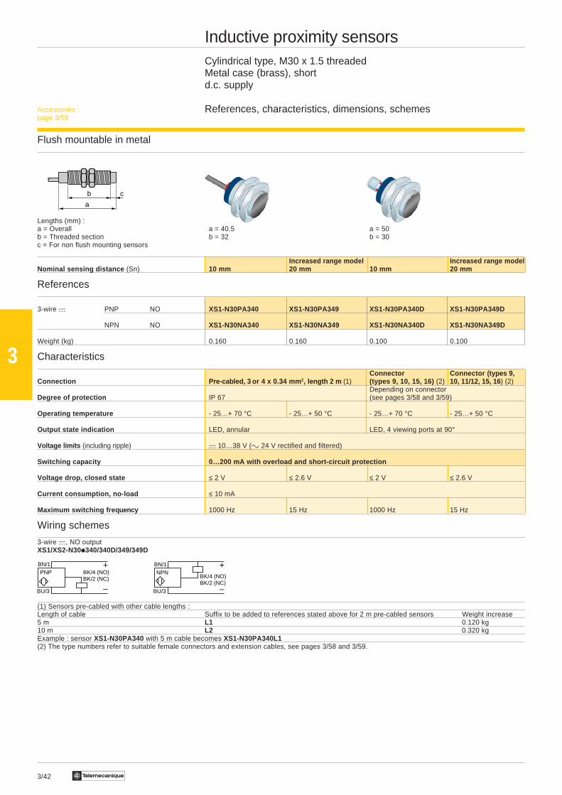
Inductive proximity sensorsCylindrical type, M30 x 1.5 threadedMetal case (brass), form Ad.c. supply
References, characteristics, dimensions, schemes
Flush mountable in metal
Lengths (mm) :a = Overall a = 60 a = 70b = Threaded section b = 51.5 b = 51.5
Nominal sensing distance (Sn) 10 mm 10 mm 10 mm 10 mm
References
3-wire a PNP NO XS1-M30PA370 – XS1-M30PA370D –
NPN NO XS1-M30NA370 – XS1-M30NA370D –
4-wire a PNP/NPN NO/NC – XS1-M30KP340 – XS1-M30KP340Duniversal model programmable
Weight (kg) 0.205 0.205 0.145 0.145
Characteristics
Connection Pre-cabled, 3 x 0.34 mm 2, length 2 m (1) Connector (types 9, 10, 15, 16) (2)Depending on connector
Degree of protection IP 68 (see pages 3/58 and 3/59)
Operating temperature - 25…+ 80 °C
Output state indication LED, annular LED, 4 viewing ports at 90°
Voltage limits (including ripple) a 10…58 V (3) a 10…38 V (4) a 10…58 V (3) a 10…38 V (4)
Switching capacity 0…200 mA with overload and short-circuit protection
Voltage drop, closed state ≤ 2 V ≤ 2.6 V ≤ 2 V ≤ 2.6 V
Current consumption, no-load ≤ 10 mA
Maximum switching fre quency 1000 Hz
Wiring schemes
3-wire a, NO output 4-wire a programmable, NO or NC outputXS1-M30ii370/370D XS1-M30KP340/340D
(1) Sensors pre-cabled with other cable lengths :Length of cable Suffix to be added to references stated above for 2 m pre-cabled sensors Weight increase5 m L1 0.120 kg10 m L2 0.320 kgExample : sensor XS1-M30PA370 with 5 m cable becomes XS1-M30PA370L1(2) The type numbers refer to suitable female connectors and extension cables, see pages 3/58 and 3/59.(3) Can be supplied with rectified c 24 V.(4) c 24 V rectified and filtered.
Accessories :page 3/59
3/45Te
3
a
b c
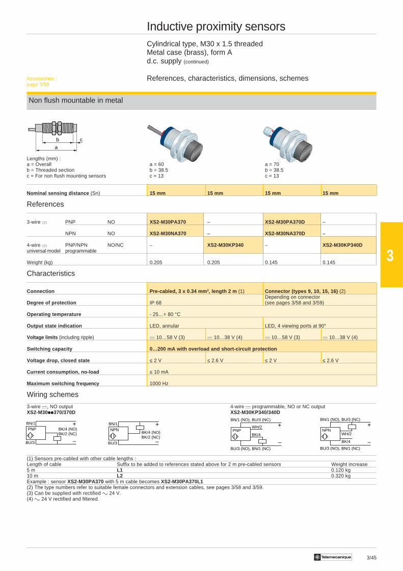
Inductive proximity sensorsCylindrical type, M30 x 1.5 threadedMetal case (brass), form Ad.c. supply (continued)
References, characteristics, dimensions, schemes
Non flush mountable in metal
Lengths (mm) :a = Overall a = 60 a = 70b = Threaded section b = 38.5 b = 38.5c = For non flush mounting sensors c = 13 c = 13
Nominal sensing distance (Sn) 15 mm 15 mm 15 mm 15 mm
References
3-wire a PNP NO XS2-M30PA370 – XS2-M30PA370D –
NPN NO XS2-M30NA370 – XS2-M30NA370D –
4-wire a PNP/NPN NO/NC – XS2-M30KP340 – XS2-M30KP340Duniversal model programmable
Weight (kg) 0.205 0.205 0.145 0.145
Characteristics
Connection Pre-cabled, 3 x 0.34 mm 2, length 2 m (1) Connector (types 9, 10, 15, 16) (2)Depending on connector
Degree of protection IP 68 (see pages 3/58 and 3/59)
Operating temperature - 25…+ 80 °C
Output state indication LED, annular LED, 4 viewing ports at 90°
Voltage limits (including ripple) a 10…58 V (3) a 10…38 V (4) a 10…58 V (3) a 10…38 V (4)
Switching capacity 0…200 mA with overload and short-circuit protection
Voltage drop, closed state ≤ 2 V ≤ 2.6 V ≤ 2 V ≤ 2.6 V
Current consumption, no-load ≤ 10 mA
Maximum switching fre quency 1000 Hz
Wiring schemes
3-wire a, NO output 4-wire a programmable, NO or NC outputXS2-M30ii370/370D XS2-M30KP340/340D
(1) Sensors pre-cabled with other cable lengths :Length of cable Suffix to be added to references stated above for 2 m pre-cabled sensors Weight increase5 m L1 0.120 kg10 m L2 0.320 kgExample : sensor XS2-M30PA370 with 5 m cable becomes XS2-M30PA370L1(2) The type numbers refer to suitable female connectors and extension cables, see pages 3/58 and 3/59.(3) Can be supplied with rectified c 24 V.(4) c 24 V rectified and filtered.
–
BN/1
BU/3
+PNP BK/4 (NO)
BK/2 (NC)
BN/1
BU/3
+
–
BK/4 (NO)BK/2 (NC)
NPN
BU/3 (NO), BN/1 (NC)
+
BK/4PNP
–
BN/1 (NO), BU/3 (NC)
WH/2 +
–
WH/2NPN
BN/1 (NO), BU/3 (NC)
BU/3 (NO), BN/1 (NC)
BK/4
Accessories :page 3/59
3/46 Te
3
a
b
BN/2
BU/3
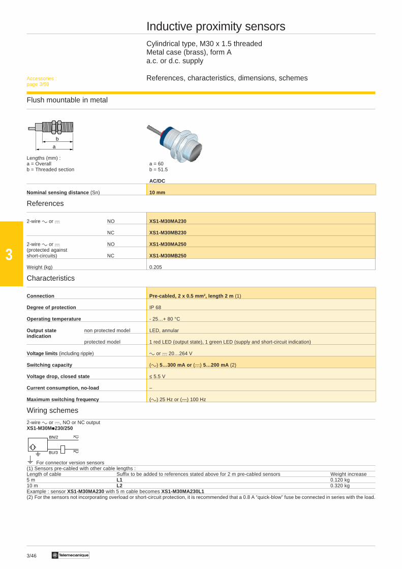
Inductive proximity sensorsCylindrical type, M30 x 1.5 threadedMetal case (brass), form Aa.c. or d.c. supply
References, characteristics, dimensions, schemes
Flush mountable in metal
Lengths (mm) :a = Overall a = 60b = Threaded section b = 51.5
AC/DC
Nominal sensing distance (Sn) 10 mm
References
2-wire c or a NO XS1-M30MA230
NC XS1-M30MB230
2-wire c or a NO XS1-M30MA250(protected againstshort-circuits) NC XS1-M30MB250
Weight (kg) 0.205
Characteristics
Connection Pre-cabled, 2 x 0.5 mm 2, length 2 m (1)
Degree of protection IP 68
Operating temperature - 25…+ 80 °C
Output state non protected model LED, annularindication
protected model 1 red LED (output state), 1 green LED (supply and short-circuit indication)
Voltage limits (including ripple) c or a 20…264 V
Switching capacity (c) 5…300 mA or (a) 5…200 mA (2)
Voltage drop, closed state ≤ 5.5 V
Current consumption, no-load –
Maximum switching fre quency (c) 25 Hz or (a) 100 Hz
Wiring schemes
2-wire c or a, NO or NC outputXS1-M30Mi230/250
For connector version sensors(1) Sensors pre-cabled with other cable lengths :Length of cable Suffix to be added to references stated above for 2 m pre-cabled sensors Weight increase5 m L1 0.120 kg10 m L2 0.320 kgExample : sensor XS1-M30MA230 with 5 m cable becomes XS1-M30MA230L1(2) For the sensors not incorporating overload or short-circuit protection, it is recommended that a 0.8 A “quick-blow” fuse be connected in series with the load.
Accessories :page 3/59

3/47Te
3
a
b c
Inductive proximity sensorsCylindrical type, M30 x 1.5 threadedMetal case (brass), form Aa.c. or d.c. supply (continued)
References, characteristics, dimensions, schemes
Non flush mountable in metal
Lengths (mm) :a = Overall a = 60b = Threaded section b = 38.5c = For non flush mounting sensors c = 13
AC/DC
Nominal sensing distance (Sn) 15 mm
References
2-wire c or a NO XS2-M30MA230
NC XS2-M30MB230
2-wire c or a NO XS2-M30MA250(protected againstshort-circuits) NC XS2-M30MB250
Weight (kg) 0.205
Characteristics
Connection Pre-cabled, 2 x 0.5 mm 2, L = 2 m (1)
Degree of protection IP 68
Operating temperature - 25…+ 80 °C
Output state non protected model LED, annularindication 1 red LED (output state)
protected model 1 green LED (supply and short-circuit indication)
Voltage limits (including ripple) c or a 20…264 V
Switching capacity (c) 5…300 mA or (a) 5…200 mA (2)
Voltage drop, closed state ≤ 5.5 V
Current consumption, no-load –
Maximum switching fre quency (c) 25 Hz or (a) 75 Hz
Wiring schemes
2-wire c or a, NO or NC outputXS2-M30ii2i0
For connector version sensors(1) Sensors pre-cabled with other cable lengths :Length of cable Suffix to be added to references stated above for 2 m pre-cabled sensors Weight increase5 m L1 0.120 kg10 m L2 0.320 kgExample : sensor XS2-M30MA230 with 5 m cable becomes XS2-M30MA230L1(2) For the sensors not incorporating overload or short-circuit protection, it is recommended that a 0.8 A “quick-blow” fuse be connected in series with the load.
BN/2
BU/3
Accessories :page 3/59
3/48 Te
3
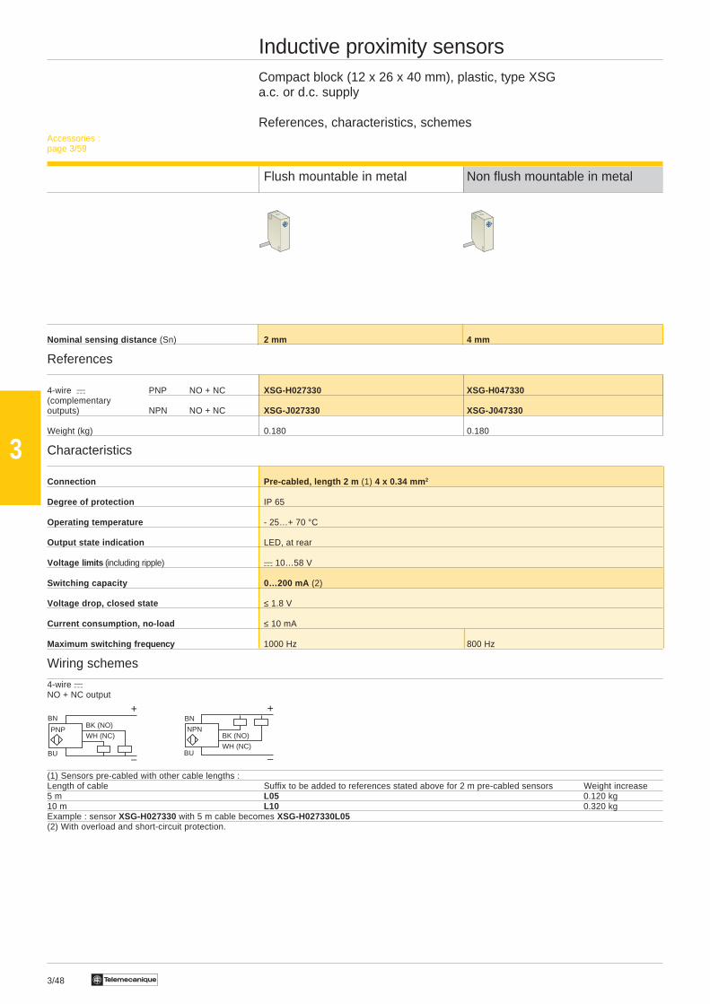
Inductive proximity sensorsCompact block (12 x 26 x 40 mm), plastic, type XSGa.c. or d.c. supply
References, characteristics, schemes
Flush mountable in metal Non flush mountable in metal
Nominal sensing distance (Sn) 2 mm 4 mm
References
4-wire a PNP NO + NC XSG-H027330 XSG-H047330(complementaryoutputs) NPN NO + NC XSG-J027330 XSG-J047330
Weight (kg) 0.180 0.180
Characteristics
Connection Pre-cabled, length 2 m (1) 4 x 0.34 mm 2
Degree of protection IP 65
Operating temperature - 25…+ 70 °C
Output state indication LED, at rear
Voltage limits (including ripple) a 10…58 V
Switching capacity 0…200 mA (2)
Voltage drop, closed state ≤ 1.8 V
Current consumption, no-load ≤ 10 mA
Maximum switching fre quency 1000 Hz 800 Hz
Wiring schemes
4-wire aNO + NC output
(1) Sensors pre-cabled with other cable lengths :Length of cable Suffix to be added to references stated above for 2 m pre-cabled sensors Weight increase5 m L05 0.120 kg10 m L10 0.320 kgExample : sensor XSG-H027330 with 5 m cable becomes XSG-H027330L05(2) With overload and short-circuit protection.
Accessories :page 3/59
BN
BU
+
–
WH (NC)PNP
BK (NO)BN
BU
+
–WH (NC)
NPNBK (NO)
3/49Te
3
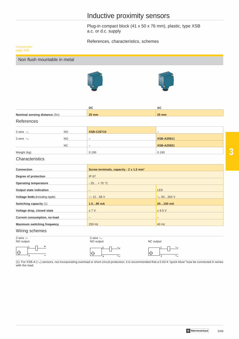
Inductive proximity sensorsPlug-in compact block (41 x 50 x 76 mm), plastic, type XSBa.c. or d.c. supply
References, characteristics, schemes
Non flush mountable in metal
DC AC
Nominal sensing distance (Sn) 25 mm 25 mm
References
2-wire a NO XSB-C25710 –
2-wire c NO – XSB-A25911
NC – XSB-A25921
Weight (kg) 0.190 0.190
Characteristics
Connection Screw terminals, capacity : 2 x 1.5 mm 2
Degree of protection IP 67
Operating temperature - 25… + 70 °C
Output state indication – LED
Voltage limits (including ripple) a 12…58 V c 93…264 V
Switching capacity (1) 1.5…80 mA 20…150 mA
Voltage drop, closed state ≤ 7 V ≤ 9.5 V
Current consumption, no-load – –
Maximum switching fre quency 250 Hz 40 Hz
Wiring schemes
2-wire a 2-wire cNO output NO output NC output
(1) For XSB-A (c) sensors, not incorporating overload or short-circuit protection, it is recommended that a 0.63 A “quick-blow” fuse be connected in serieswith the load.
Accessories :page 3/59
1
4
+
–
1
2
3
4
3/50 Te
3
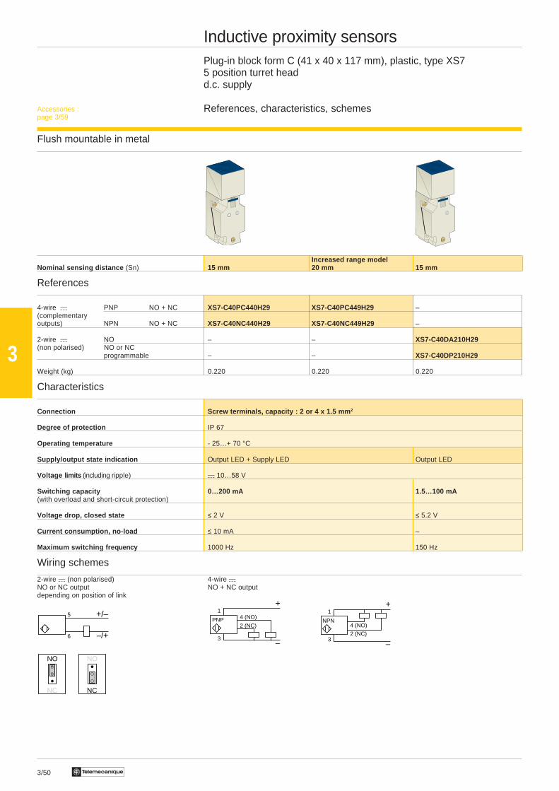
Inductive proximity sensorsPlug-in block form C (41 x 40 x 117 mm), plastic, type XS75 position turret headd.c. supply
References, characteristics, schemes
Flush mountable in metal
Increased range modelNominal sensing distance (Sn) 15 mm 20 mm 15 mm
References
4-wire a PNP NO + NC XS7-C40PC440H29 XS7-C40PC449H29 –(complementaryoutputs) NPN NO + NC XS7-C40NC440H29 XS7-C40NC449H29 –
2-wire a NO – – XS7-C40DA210H29(non polarised) NO or NC
programmable – – XS7-C40DP210H29
Weight (kg) 0.220 0.220 0.220
Characteristics
Connection Screw terminals, capacity : 2 or 4 x 1.5 mm 2
Degree of protection IP 67
Operating temperature - 25…+ 70 °C
Supply/output state indication Output LED + Supply LED Output LED
Voltage limits (including ripple) a 10…58 V
Switching capacity 0…200 mA 1.5…100 mA(with overload and short-circuit protection)
Voltage drop, closed state ≤ 2 V ≤ 5.2 V
Current consumption, no-load ≤ 10 mA –
Maximum switching fre quency 1000 Hz 150 Hz
Wiring schemes
2-wire a (non polarised) 4-wire aNO or NC output NO + NC outputdepending on position of link
5
6
+/–
–/+
NO
NC
NO
NC
1
3
+
–2 (NC)
NPN4 (NO)
1
3
+
–
2 (NC)PNP 4 (NO)
Accessories :page 3/59
3/51Te
3
5
6
+/–
–/+
NO
NC
NO
NC
1
3
+
–
2 (NC)PNP 4 (NO)
1
3
+
–2 (NC)
NPN4 (NO)
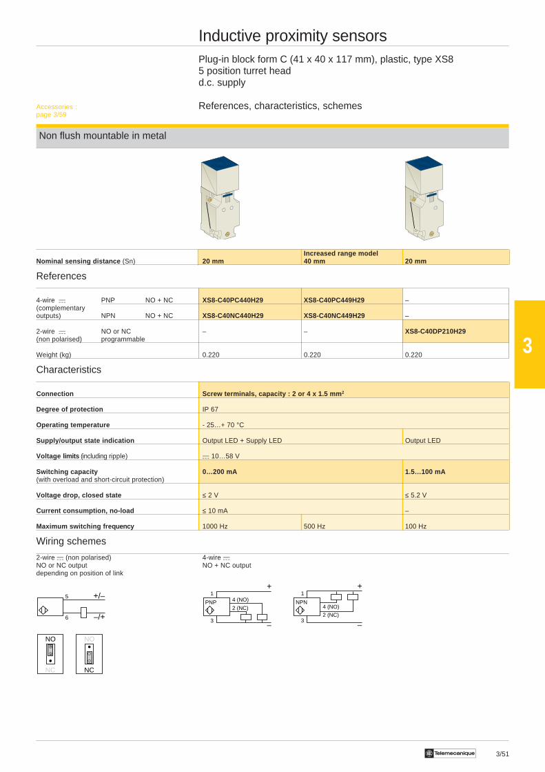
Inductive proximity sensorsPlug-in block form C (41 x 40 x 117 mm), plastic, type XS85 position turret headd.c. supply
References, characteristics, schemes
Non flush mountable in metal
Increased range modelNominal sensing distance (Sn) 20 mm 40 mm 20 mm
References
4-wire a PNP NO + NC XS8-C40PC440H29 XS8-C40PC449H29 –(complementaryoutputs) NPN NO + NC XS8-C40NC440H29 XS8-C40NC449H29 –
2-wire a NO or NC – – XS8-C40DP210H29(non polarised) programmable
Weight (kg) 0.220 0.220 0.220
Characteristics
Connection Screw terminals, capacity : 2 or 4 x 1.5 mm 2
Degree of protection IP 67
Operating temperature - 25…+ 70 °C
Supply/output state indication Output LED + Supply LED Output LED
Voltage limits (including ripple) a 10…58 V
Switching capacity 0…200 mA 1.5…100 mA(with overload and short-circuit protection)
Voltage drop, closed state ≤ 2 V ≤ 5.2 V
Current consumption, no-load ≤ 10 mA –
Maximum switching fre quency 1000 Hz 500 Hz 100 Hz
Wiring schemes
2-wire a (non polarised) 4-wire aNO or NC output NO + NC outputdepending on position of link
Accessories :page 3/59
3/52 Te
3
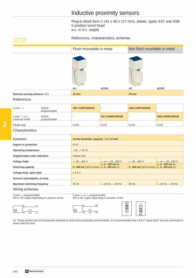
Inductive proximity sensorsPlug-in block form C (41 x 40 x 117 mm), plastic, types XS7 and XS85 position turret heada.c. or d.c. supply
References, characteristics, schemes
Flush mountable in metal Non flush mountable in metal
AC AC/DC AC AC/DC
Nominal sensing distance (Sn) 15 mm 20 mm
References
2-wire c NO/NC XS7-C40FP260H29 – XS8-C40FP260H29 –programmable
2-wire c or a NO/NC – XS7-C40MP230H29 – XS8-C40MP230H29universal model programmable
Weight (kg) 0.220 0.220 0.220 0.220
Characteristics
Connection Screw terminals, capacity : 2 x 1.5 mm 2
Degree of protection IP 67
Operating temperature - 25…+ 70 °C
Supply/output state indication Output LED
Voltage limits c 20…264 V c or a 20…264 V c 20…264 V c or a 20…264 Vccccc 5…300 mA or ccccc 5…300 mA or
Switching capacity 5…500 mA (1)(2 A inrush) aaaaa 5…200 mA (1) 5…500 mA (1)(2 A inrush) aaaaa 5…200 mA (1)
Voltage drop, open state ≤ 5.5 V
Current consumption, no-load –
Maximum switching fre quency 25 Hz c 25 Hz, a 50 Hz 25 Hz c 25 Hz, a 50 Hz
Wiring schemes
2-wire c programmable 2-wire c or a programmableNO or NC output depending on position of link NO or NC output depending on position of link
(1) These sensors do not incorporate overload or short-circuit protection and therefore, it is recommended that a 0.8 A “quick-blow” fuse be connected inseries with the load.
Accessories :pages 3/59
NO
NC
NO
NC
5
6
5
6
3/53Te
3
Accessories :page 3/59
1
3
+
–
2 (NC)PNP
4 (NO)1
3
+
–2 (NC)
NPN4 (NO)
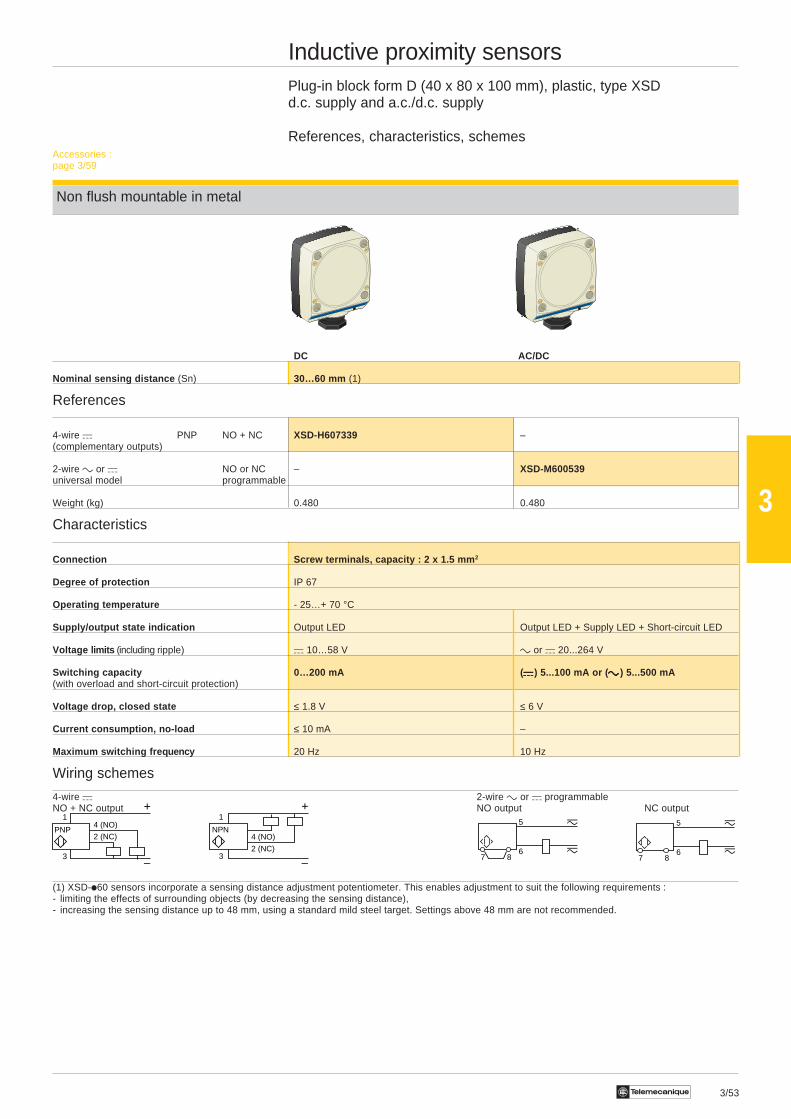
Inductive proximity sensorsPlug-in block form D (40 x 80 x 100 mm), plastic, type XSDd.c. supply and a.c./d.c. supply
References, characteristics, schemes
Non flush mountable in metal
DC AC/DC
Nominal sensing distance (Sn) 30…60 mm (1)
References
4-wire a PNP NO + NC XSD-H607339 –(complementary outputs)
2-wire c or a NO or NC – XSD-M600539universal model programmable
Weight (kg) 0.480 0.480
Characteristics
Connection Screw terminals, capacity : 2 x 1.5 mm 2
Degree of protection IP 67
Operating temperature - 25…+ 70 °C
Supply/output state indication Output LED Output LED + Supply LED + Short-circuit LED
Voltage limits (including ripple) a 10…58 V c or a 20...264 V
Switching capacity 0…200 mA ( aaaaa) 5...100 mA or ( ccccc ) 5...500 mA(with overload and short-circuit protection)
Voltage drop, closed state ≤ 1.8 V ≤ 6 V
Current consumption, no-load ≤ 10 mA –
Maximum switching fre quency 20 Hz 10 Hz
Wiring schemes
4-wire a 2-wire c or a programmableNO + NC output NO output NC output
(1) XSD-i60 sensors incorporate a sensing distance adjustment potentiometer. This enables adjustment to suit the following requirements :- limiting the effects of surrounding objects (by decreasing the sensing distance),- increasing the sensing distance up to 48 mm, using a standard mild steel target. Settings above 48 mm are not recommended.
5
687
5
687
3/54 Te
3
a
b
3
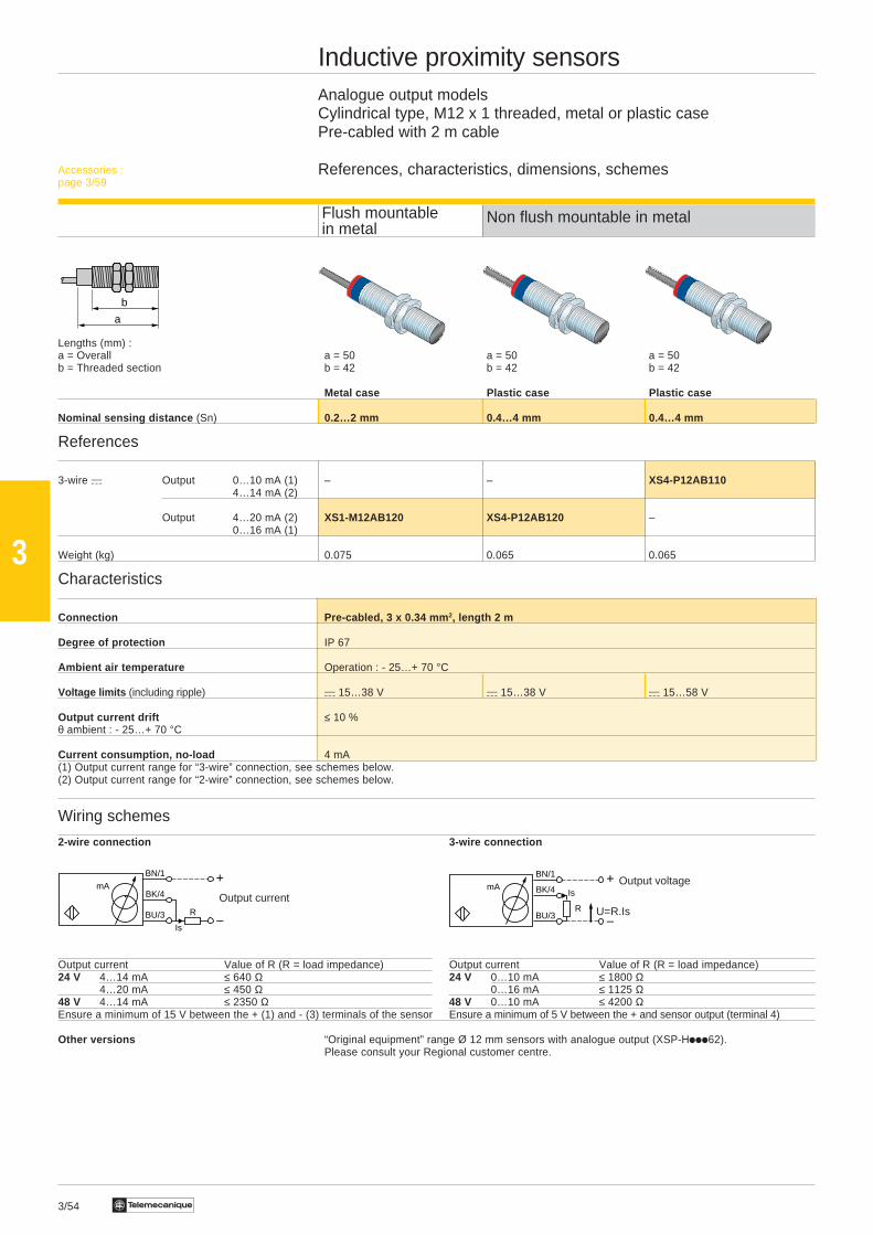
Inductive proximity sensorsAnalogue output modelsCylindrical type, M12 x 1 threaded, metal or plastic casePre-cabled with 2 m cable
References, characteristics, dimensions, schemes
Non flush mountable in metal
Lengths (mm) :a = Overall a = 50 a = 50 a = 50b = Threaded section b = 42 b = 42 b = 42
Metal case Plastic case Plastic case
Nominal sensing distance (Sn) 0.2…2 mm 0.4…4 mm 0.4…4 mm
References
3-wire a Output 0…10 mA (1) – – XS4-P12AB1104…14 mA (2)
Output 4…20 mA (2) XS1-M12AB120 XS4-P12AB120 –0…16 mA (1)
Weight (kg) 0.075 0.065 0.065
Characteristics
Connection Pre-cabled, 3 x 0.34 mm 2, length 2 m
Degree of protection IP 67
Ambient air temperature Operation : - 25…+ 70 °C
Voltage limits (including ripple) a 15…38 V a 15…38 V a 15…58 V
Output current drift ≤ 10 %θ ambient : - 25…+ 70 °C
Current consumption, no-load 4 mA(1) Output current range for “3-wire” connection, see schemes below.(2) Output current range for “2-wire” connection, see schemes below.
Wiring schemes
2-wire connection 3-wire connection
Output current Value of R (R = load impedance) Output current Value of R (R = load impedance)24 V 4…14 mA ≤ 640 Ω 24 V 0…10 mA ≤ 1800 Ω
4…20 mA ≤ 450 Ω 0…16 mA ≤ 1125 Ω48 V 4…14 mA ≤ 2350 Ω 48 V 0…10 mA ≤ 4200 ΩEnsure a minimum of 15 V between the + (1) and - (3) terminals of the sensor Ensure a minimum of 5 V between the + and sensor output (terminal 4)
Other versions “Original equipment” range Ø 12 mm sensors with analogue output (XSP-Hiii62).Please consult your Regional customer centre.
Accessories :page 3/59
Flush mountablein metal
Output voltageBN/1
BK/4
BU/3R
mA
–
+Is
U=R.IsOutput current
BN/1
BK/4
BU/3 R
mA
–
+
Is
3/55Te
3
a
b c
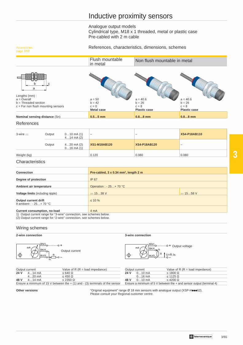
Inductive proximity sensorsAnalogue output modelsCylindrical type, M18 x 1 threaded, metal or plastic casePre-cabled with 2 m cable
References, characteristics, dimensions, schemes
Non flush mountable in metal
Lengths (mm) :a = Overall a = 50 a = 40.6 a = 40.6b = Threaded section b = 42 b = 26 b = 26c = For non flush mounting sensors c = 0 c = 8 c = 8
Metal case Plastic case Plastic case
Nominal sensing distance (Sn) 0.5…5 mm 0.8…8 mm 0.8…8 mm
References
3-wire a Output 0…10 mA (1) – – XS4-P18AB1104…14 mA (2)
Output 4…20 mA (2) XS1-M18AB120 XS4-P18AB120 –0…16 mA (1)
Weight (kg) 0.120 0.080 0.080
Characteristics
Connection Pre-cabled, 3 x 0.34 mm 2, length 2 m
Degree of protection IP 67
Ambient air temperature Operation : - 25…+ 70 °C
Voltage limits (including ripple) a 15…38 V a 15…58 V
Output current drift ≤ 10 %θ ambient : - 25…+ 70 °C
Current consumption, no-load 4 mA1) Output current range for “3-wire” connection, see schemes below.(2) Output current range for “2-wire” connection, see schemes below.
Wiring schemes
2-wire connection 3-wire connection
Output current Value of R (R = load impedance) Output current Value of R (R = load impedance)24 V 4…14 mA ≤ 640 Ω 24 V 0…10 mA ≤ 1800 Ω
4…20 mA ≤ 450 Ω 0…16 mA ≤ 1125 Ω48 V 4…14 mA ≤ 2350 Ω 48 V 0…10 mA ≤ 4200 ΩEnsure a minimum of 15 V between the + (1) and - (3) terminals of the sensor Ensure a minimum of 5 V between the + and sensor output (terminal 4)
Other versions “Original equipment” range Ø 18 mm sensors with analogue output (XSP-Hiii62).Please consult your Regional customer centre.
Flush mountablein metal
Accessories :page 3/59
Output voltageBN/1
BK/4
BU/3R
mA
–
+Is
U=R.IsOutput current
BN/1
BK/4
BU/3 R
mA
–
+
Is
3/56 Te
3
a
b c
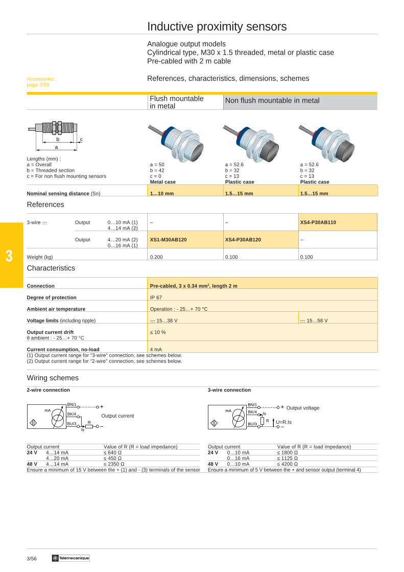
Inductive proximity sensorsAnalogue output modelsCylindrical type, M30 x 1.5 threaded, metal or plastic casePre-cabled with 2 m cable
References, characteristics, dimensions, schemes
Non flush mountable in metal
Lengths (mm) :a = Overall a = 50 a = 52.6 a = 52.6b = Threaded section b = 42 b = 32 b = 32c = For non flush mounting sensors c = 0 c = 13 c = 13
Metal case Plastic case Plastic case
Nominal sensing distance (Sn) 1…10 mm 1.5…15 mm 1.5…15 mm
References
3-wire a Output 0…10 mA (1) – – XS4-P30AB1104…14 mA (2)
Output 4…20 mA (2) XS1-M30AB120 XS4-P30AB120 –0…16 mA (1)
Weight (kg) 0.200 0.100 0.100
Characteristics
Connection Pre-cabled, 3 x 0.34 mm 2, length 2 m
Degree of protection IP 67
Ambient air temperature Operation : - 25…+ 70 °C
Voltage limits (including ripple) a 15…38 V a 15…58 V
Output current drift ≤ 10 %θ ambient : - 25…+ 70 °C
Current consumption, no-load 4 mA(1) Output current range for “3-wire” connection, see schemes below.(2) Output current range for “2-wire” connection, see schemes below.
Wiring schemes
2-wire connection 3-wire connection
Output current Value of R (R = load impedance) Output current Value of R (R = load impedance)24 V 4…14 mA ≤ 640 Ω 24 V 0…10 mA ≤ 1800 Ω
4…20 mA ≤ 450 Ω 0…16 mA ≤ 1125 Ω48 V 4…14 mA ≤ 2350 Ω 48 V 0…10 mA ≤ 4200 ΩEnsure a minimum of 15 V between the + (1) and - (3) terminals of the sensor Ensure a minimum of 5 V between the + and sensor output (terminal 4)
Flush mountablein metal
Accessories :page 3/59
Output voltageBN/1
BK/4
BU/3R
mA
–
+Is
U=R.IsOutput current
BN/1
BK/4
BU/3 R
mA
–
+
Is
3/57Te
3
a
b
Ø
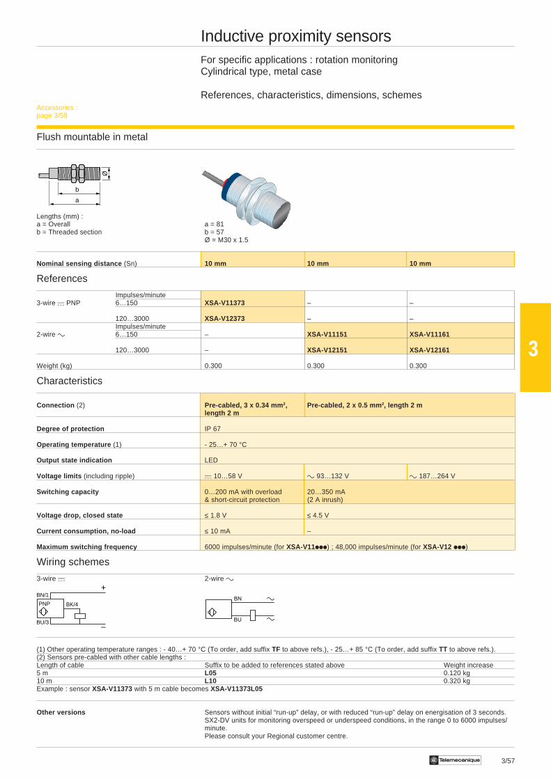
Inductive proximity sensorsFor specific applications : rotation monitoringCylindrical type, metal case
References, characteristics, dimensions, schemes
Flush mountable in metal
Lengths (mm) :a = Overall a = 81b = Threaded section b = 57
Ø = M30 x 1.5
Nominal sensing distance (Sn) 10 mm 10 mm 10 mm
References
Impulses/minute3-wire a PNP 6…150 XSA-V11373 – –
120…3000 XSA-V12373 – –Impulses/minute
2-wire c 6…150 – XSA-V11151 XSA-V11161
120…3000 – XSA-V12151 XSA-V12161
Weight (kg) 0.300 0.300 0.300
Characteristics
Connection (2) Pre-cabled, 3 x 0.34 mm 2, Pre-cabled, 2 x 0.5 mm 2, length 2 mlength 2 m
Degree of protection IP 67
Operating temperature (1) - 25…+ 70 °C
Output state indication LED
Voltage limits (including ripple) a 10…58 V c 93…132 V c 187…264 V
Switching capacity 0…200 mA with overload 20…350 mA& short-circuit protection (2 A inrush)
Voltage drop, closed state ≤ 1.8 V ≤ 4.5 V
Current consumption, no-load ≤ 10 mA –
Maximum switching frequency 6000 impulses/minute (for XSA-V11iii) ; 48,000 impulses/minute (for XSA-V12 iii)
Wiring schemes
3-wire a 2-wire c
(1) Other operating temperature ranges : - 40…+ 70 °C (To order, add suffix TF to above refs.), - 25…+ 85 °C (To order, add suffix TT to above refs.).(2) Sensors pre-cabled with other cable lengths :Length of cable Suffix to be added to references stated above Weight increase5 m L05 0.120 kg10 m L10 0.320 kgExample : sensor XSA-V11373 with 5 m cable becomes XSA-V11373L05
Other versions Sensors without initial “run-up” delay, or with reduced “run-up” delay on energisation of 3 seconds.SX2-DV units for monitoring overspeed or underspeed conditions, in the range 0 to 6000 impulses/minute.Please consult your Regional customer centre.
Accessories :page 3/59
BN/1
BU/3
+
–
BK/4PNPBN
BU

3/58 Te
3
Inductive proximity sensorsFemale connectors
References, characteristics, dimensions, schemes
Connector type N o 9 10 11 12
Number of pins 4 4 4 4
Female connector version M12 straight M12 elbowed M12 elbowed M12 elbowed
References
PVR cable connection, L = 2 m XZ-CP1141L2 XZ-CP1241L2 XZ-CP1340L2 XZ-CP1440L2Ø 5 mm
L = 5 m XZ-CP1141L5 XZ-CP1241L5 XZ-CP1340L5 XZ-CP1440L5
L = 10 m XZ-CP1141L10 XZ-CP1241L10 XZ-CP1340L10 XZ-CP1440L10
Weight (kg) 0.090 (L = 2 m), 0.190 (L = 5 m), 0.370 (L = 10 m) 0.080 (L = 2 m), 0.180 (L = 5 m), 0.350 (L = 10 m)
Characteristics
Wiring configuration, PNP/NPN – – PNP wiring NPN wiring
Degree of protection IP 67 IP 67 IP 67 IP 67
Ambient air temperature -35…+80 °C -35…+80 °C -35…+80 °C -35…+80 °C
Number of wires and c.s.a. 4 x 0.25 mm2 4 x 0.25 mm2 3 x 0.25 mm2 3 x 0.25 mm2
LED indication No No 2 LEDs 2 LEDs
Associated sensor references XS iiiii-iiiiiiiiiiiiiiiiiiiiiiiiiiiiiiiiiiiiiiiiD XSiiiii -iiiiiiiiiiiiiiiiiiiiiiiiiiiiiiiiiiiiiiiiD XSiiiii -iiiiiiiiiiiiiiiiiiiiiiiiiiiiiiiiiiiiiiiiD XSiiiii -iiiiiiiiiiiiiiiiiiiiiiiiiiiiiiiiiiiiiiiiD
Dimensions
XZ-CP1141Liiiii XZ-CP1241Liiiii XZ-CP1340Liiiii , XZ-CP1440Liiiii XZ-CP1865Liiiii XZ-CP1965Liiiii
(1) 2 LEDs,voltage limits
L = 2, 5 or 10 m a 10…30 V max.
Connection schemes
XZ-CP1iiiii41Liiiii XZ-CP1iiiii41Liiiii LED connections XZ-CP1iiiii65LiiiiiXZ-CP1340Liiiii XZ-CP1440Liiiii
Ø14,5
42L
M12x1 26
20
32
40
L
M12x1 27
20
32
40
L
(1)
M12x1 1/2" 20 UNFØ14,5
42L
26
20
32
40
L
1/2" 20 UNF
3 4
2 1
BU BK
BN
3 4
2 1
BU BK
WH BN
BN
BK
BU
YWGN
+
–
1
2
3
4
PNP
Signal
BU
BK
BN
YWGN
–
+
4
3
2
1
NPN
Signal
1
23
RD/WH
GN
RD/BK

3/59Te
3
Inductive proximity sensorsFemale connectors (continued) and sensor fixing accessory
References, characteristics, dimensions, schemes
Connector type N o 13 14
Number of pins 3 3
Female connector version 1/2" 20 UNF straight 1/2" 20 UNF straight
References
PVR cable connection, L = 2 m XZ-CP1865L2 XZ-CP1965L2Ø 5 mm
L = 5 m XZ-CP1865L5 XZ-CP1965L5
L = 10 m XZ-CP1865L10 XZ-CP1965L10
Weight (kg) 0.080 (L = 2 m), 0.180 (L= 5 m), 0.350 (L = 10 m)
Characteristics
Wiring configuration, PNP/NPN – –
Degree of protection IP 67 IP 67
Ambient air temperature -35…+80 °C -35…+80 °C
Number of wires and c.s.a. 3 x 0.34 mm2 3 x 0.34 mm2
LED indication No No
Associated sensor references XS iiiii -iiiiiiiiiiiiiiiiiiiiiiiiiiiiiiiiiiiiiiiiK XSiiiii -iiiiiiiiiiiiiiiiiiiiiiiiiiiiiiiiiiiiiiiiK
Dimensions and connection schemes
Shown on previous page
Saddle clamp fixing accessory for cylindrical type sensorsDescription For use with sensors Reference Weight
Type Diameter (mm) kg
Saddle clamps XS1 4 (plain) XSZ-B104 0.005
5 (M5 x 0.5) XSZ-B105 0.005
XS1, XS2 6.5 (plain) XSZ-B165 0.005
XS1, XS2, XS4 8 (M8 x 1) XSZ-B108 0.006
12 (M12 x 1) XSZ-B112 0.006
18 (M18 x 1) XSZ-B118 0.010
XS1, XS2, XS4 30 (M30 x 1.5) XSZ-B130 0.020
XSZ-B1ii