
INDUCTIVE HEATING OF A CYLINDRICAL FLUIDIZED...
12
627 Journal of Chemical Technology and Metallurgy, 51, 6, 2016, 627-638 INTRODUCTION Disperse particle populations in fluidized beds are brought by fluid media into a fluidized state. The latter is known for quite some time. It was patented in 1922 by Winkler as a special process named a fluidized bed [1]. In fact a fluidized bed is created when a fluid medium flows through a particle collective from the bottom to the top, i.e. against gravity, at a rate that is greater than the loosening velocity and less than the export velocity of the particles in the particle collective. There is an intense movement of the particles in this speed range, which on one hand results in their good mixing, while on the other, provides a close contact between the particles and the fluid medium. This state has been known for about 100 years and its advantages have been industrially used in various forms [2 - 9]. The fluid medium, for example, flowing through the layer at a temperature which is higher or lower than the temperature of the particles present in the layer, brings about heat transfer to or from the particles. As a result, the particles are heated or cooled, optionally dried or subjected simultaneously with the injection of fluids containing dissolved or suspended solids to coating or destruction. The case referring to heat and mass transfer proceeding can be the basis of certain model calculations [10 - 12]. The disadvantage of this ap- proach is, inter alia, that the entering fluidizing medium (e.g. air for drying processes) may be loaded only up to its saturation with water vapor. For example, in case of heating processes in a fluidized bed the only possibility to increase the registered amount of heat required is to increase either the flow rate of the fluidized medium or its temperature. The former solution is however limited by the rate of particles discharge, while the latter one is not always possible, e. g. with thermolabile goods. The method of contactless energy input to fluid- ized beds by inductive heating of inert bodies, which is studied here, can be an alternative. If some of the fluidized particles are electrically conductive one (e. g., iron hollow spheres [13]) and an alternating magnetic field is applied, energy is fed due to eddy currents on the surface of the balls. This results in warming of the iron hollow balls, which in turn affects the fluidization behavior of the fluidized bed [14 - 18]. The registered thermal energy is transferred to the particles with swirl- ing through the fluidization medium [19 - 21]. Thus the particles can be heated, dried, granulated, liquid injected, or destructively coated [22]. One of the advantages of ABSTRACT Fluidized bed apparatuses have various procedural advantages and are widely used in many industrial processes, such as drying, granulation, agglomeration or coating. Besides the conventional method of energy input to fluidized beds by convection, the energy input can also be realized by induction through electrically conductive inert particles and an electromagnetic field. A new alternative method of energy input to cylindrical fluidized beds is described in this work. A simplified method of calculating the heat transfer in an inductively heated fluidized bed is presented. Keywords: fluidized bed, induction fields, inductive heating, electrically conductive iron hollow balls. INDUCTIVE HEATING OF A CYLINDRICAL FLUIDIZED BED Vesselin Idakiev, Andreas Bück, Evangelos Tsotsas, Lothar Mörl Otto von Guericke University Magdeburg Universitätsplatz 2, 39106 Magdeburg, Germany E-mail: [email protected] Received 04 July 2016 Accepted 07 September 2016
Transcript of INDUCTIVE HEATING OF A CYLINDRICAL FLUIDIZED...

Vesselin Idakiev, Andreas Bück, Evangelos Tsotsas, Lothar Mörl
627
Journal of Chemical Technology and Metallurgy, 51, 6, 2016, 627-638
INTRODUCTION
Disperse particle populations in fluidized beds are brought by fluid media into a fluidized state. The latter is known for quite some time. It was patented in 1922 by Winkler as a special process named a fluidized bed [1]. In fact a fluidized bed is created when a fluid medium flows through a particle collective from the bottom to the top, i.e. against gravity, at a rate that is greater than the loosening velocity and less than the export velocity of the particles in the particle collective. There is an intense movement of the particles in this speed range, which on one hand results in their good mixing, while on the other, provides a close contact between the particles and the fluid medium. This state has been known for about 100 years and its advantages have been industrially used in various forms [2 - 9]. The fluid medium, for example, flowing through the layer at a temperature which is higher or lower than the temperature of the particles present in the layer, brings about heat transfer to or from the particles. As a result, the particles are heated or cooled, optionally dried or subjected simultaneously with the injection of fluids containing dissolved or suspended solids to coating or destruction. The case referring to heat
and mass transfer proceeding can be the basis of certain model calculations [10 - 12]. The disadvantage of this ap-proach is, inter alia, that the entering fluidizing medium (e.g. air for drying processes) may be loaded only up to its saturation with water vapor. For example, in case of heating processes in a fluidized bed the only possibility to increase the registered amount of heat required is to increase either the flow rate of the fluidized medium or its temperature. The former solution is however limited by the rate of particles discharge, while the latter one is not always possible, e. g. with thermolabile goods.
The method of contactless energy input to fluid-ized beds by inductive heating of inert bodies, which is studied here, can be an alternative. If some of the fluidized particles are electrically conductive one (e. g., iron hollow spheres [13]) and an alternating magnetic field is applied, energy is fed due to eddy currents on the surface of the balls. This results in warming of the iron hollow balls, which in turn affects the fluidization behavior of the fluidized bed [14 - 18]. The registered thermal energy is transferred to the particles with swirl-ing through the fluidization medium [19 - 21]. Thus the particles can be heated, dried, granulated, liquid injected, or destructively coated [22]. One of the advantages of
ABSTRACT
Fluidized bed apparatuses have various procedural advantages and are widely used in many industrial processes, such as drying, granulation, agglomeration or coating. Besides the conventional method of energy input to fluidized beds by convection, the energy input can also be realized by induction through electrically conductive inert particles and an electromagnetic field.
A new alternative method of energy input to cylindrical fluidized beds is described in this work. A simplified method of calculating the heat transfer in an inductively heated fluidized bed is presented.
Keywords: fluidized bed, induction fields, inductive heating, electrically conductive iron hollow balls.
INDUCTIVE HEATING OF A CYLINDRICAL FLUIDIZED BED
Vesselin Idakiev, Andreas Bück, Evangelos Tsotsas, Lothar Mörl
Otto von Guericke University MagdeburgUniversitätsplatz 2, 39106 Magdeburg, GermanyE-mail: [email protected]
Received 04 July 2016Accepted 07 September 2016
Journal of Chemical Technology and Metallurgy, 51, 6, 2016
628
such a process refers to the time behavior of the heated fluidized bed [23].
The present contribution reports an investigation aimed at elucidating some features of the process of inductive energy input to cylindrical fluidized beds. A simplified model of calculating the temperatures in the inductively heated fluidized bed is developed.
EXPERIMENTAL
An experimental fluidized bed system with in-ductive heating
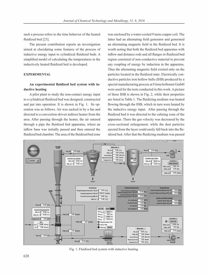
A pilot plant to study the non-contact energy input to a cylindrical fluidized bed was designed, constructed and put into operation. It is shown in Fig. 1. Its op-eration was as follows. Air was sucked in by a fan and directed to a convection-driven indirect heater from the area. After passing through the heater, the air entered through a pipe the fluidized bed apparatus, where an inflow base was initially passed and then entered the fluidized bed chamber. The area of the fluidized bed zone
was enclosed by a water-cooled 9 turns copper coil. The latter had an alternating field generator and generated an alternating magnetic field in the fluidized bed. It is worth noting that both the fluidized bed apparatus with inflow and distance rods and all flanges in fluidized bed region consisted of non-conductive material to prevent any coupling of energy by induction in the apparatus. Thus the alternating magnetic field existed only on the particles located in the fluidized state. Electrically con-ductive particles iron hollow balls (IHB) produced by a special manufacturing process at Firma hollomet GmbH were used for the tests conducted in this work. A picture of these IHB is shown in Fig. 2, while their properties are listed in Table 1. The fluidizing medium was heated flowing through the IHB, which in turn were heated by the inductive energy input. After passing through the fluidized bed it was directed to the calming zone of the apparatus. There the gas velocity was decreased by the cross-sectional enlargement, while the dust particles ejected from the layer could easily fall back into the flu-idized bed. After that the fluidizing medium was passed
Fig. 1. Fluidized bed system with inductive heating.

Vesselin Idakiev, Andreas Bück, Evangelos Tsotsas, Lothar Mörl
629
through a cyclone separator and a filter. Both facilities were used for deposition of the dust particles torn from the fluidization medium. Then the dust free fluidization medium was directed to the environment through a sec-ond fan. As seen from Fig. 1 all temperature, pressure and air humidity values were measured at intervals of a second by electronic sensors and stored in electronic files at different locations in the plant.
The fluidized bed was the central component of the experimental plant. Fig. 3 shows a photo of this section of the plant. It is seen that the pipelines of the fluidized bed were made of borosilicate glass for better visual observation. A perforated plate of a thickness of 1 mm and openings diameter of 0.8 mm served as the inflow of the fluidized bed. The aperture ratio, i.e. the holes area referred to the total area of the floor amounted to 15 %. It was made of non-conductive plastic material. A
two-fluid nozzle of Schlick model 940 (see Fig. 4) was centrally located in the middle of the inflow. It served for a solution or a liquid injection as suggested in ref. [4] in case of a bottom-spray process.
IHB were used for the experimental tests. The manufacturing method used provided the production of such inert bodies of different density and diameter
Fig. 2. Picture of the electrically conductive IHB used.
Fig. 3. A picture of the fluidized bed plant with inductive heating.
Parameter Formal sign Value Dimension Particle diameter d 6,75 [ ]mm Apparent density
schρ 693
3mkg
Metal layer density Eρ 7800
3mkg
Air density Lρ 1,20
3mkg
Metal layer thickness s 0,12 [ ]mm Sphericity SPHT3 0,99 [ ]− Layermass PM 3,00 [ ]kg
Table 1. Characteristics of the iron hollow balls (IHB) used.

Journal of Chemical Technology and Metallurgy, 51, 6, 2016
630
[13].They were warmed up by the application of the alternating magnetic field and gave their heat to the fluidized medium. The uncontrolled electricity flows on the particle surface in the fluidized bed could be avoided by using IHB with an insulating layer. Fig. 5 illustrates these possibilities.
The apparent density of the fluidization particles, especially if different particles in a fluidized bed are used, is required as it refers to the particle diameter and the physical characteristics (density and kinematic vis-cosity) of the fluid. Different apparent densities of IHB can be obtained by choosing their thickness at a constant particles diameter. The relationship between the layer thickness, the ball diameter, the pure solid density, the air density and the apparent particles density is shown in Fig. 6. Thus, for example, the layer thickness, s , of the IHB of a known or easily measurable apparent density of the balls, schρ , can be estimated taking into consid-
eration the density of the iron shell, Eρ , and the air density, Lρ , at a readily measurable ball diameter, d .
Simplified modeling of fluidization medium heat-ing through inductive energy input
The pilot plant described above was used to follow the introduction of energy to the fluidized bed by induc-ing electrically conductive IHB of a different diameter. The test program compiled in Table 2 shows how the temperature of the particles, of the apparatus wall and of the fluidized medium can be calculated on the ground of a simplistic model. The detailed derivation of this model is presented in the paper of Idakiev et al. [20]. Five tests with inductive heating of the cylindrical fluidized bed were carried out to validate the model. The supplied power in these tests was systematically varied. A number of simplifying assumptions was applied. It was accepted that: (i) the particles were inert, monodispersed and
Fig. 4. A picture of the distributor plate and two-fluid noz-zle used.
Fig. 5. A schematic presentation of electrically conductive particles.
Fig. 6. A scheme presenting the correlation between the apparent density and the layer thickness.
Fig. 7. A schematic illustration of the model advanced.
Vesselin Idakiev, Andreas Bück, Evangelos Tsotsas, Lothar Mörl
631
homogeneous; (ii) there was no drying and no chemical reaction; (iii) the fluidized bed was homogeneous; (iv) the electric power supply was effective immediately after switching on the field; (v) no bypasses occurred in the fluidized bed.
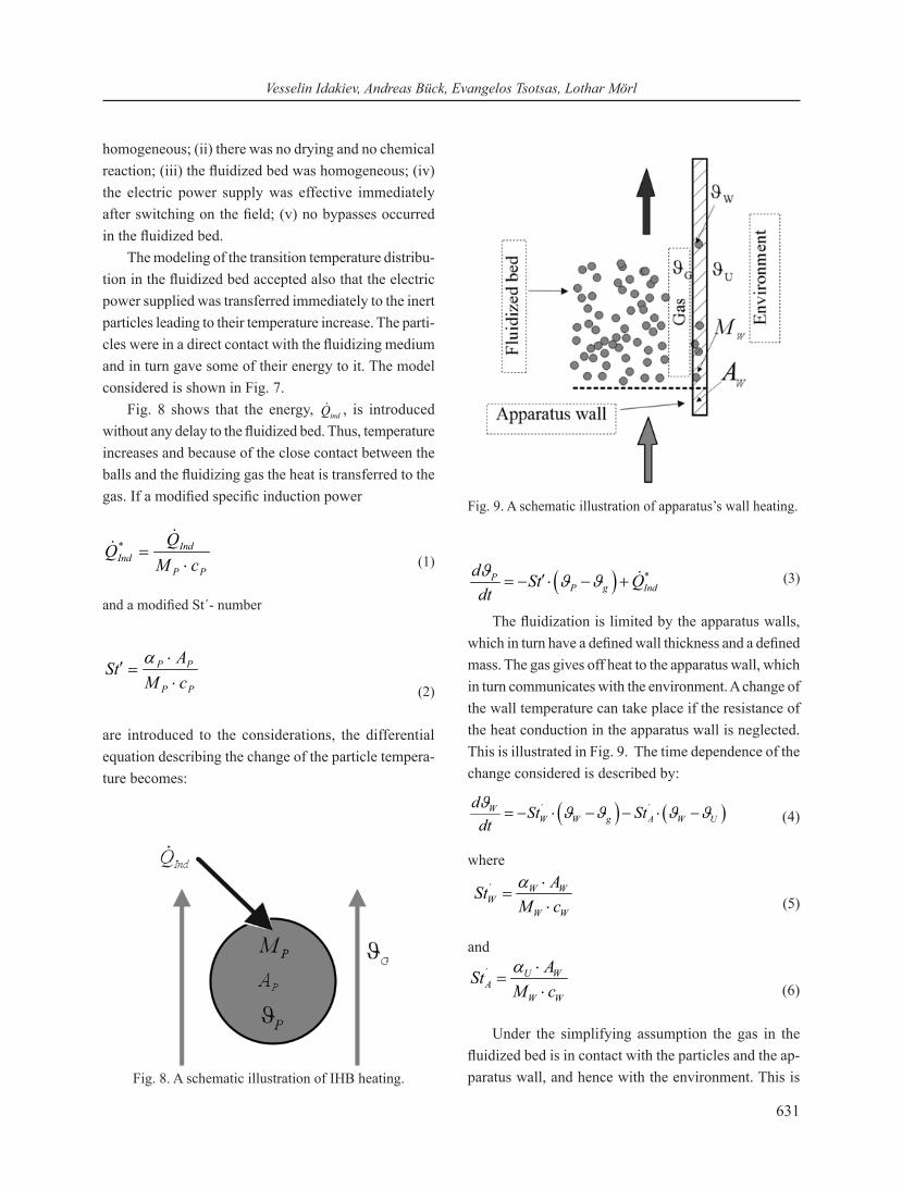
The modeling of the transition temperature distribu-tion in the fluidized bed accepted also that the electric power supplied was transferred immediately to the inert particles leading to their temperature increase. The parti-cles were in a direct contact with the fluidizing medium and in turn gave some of their energy to it. The model considered is shown in Fig. 7.
Fig. 8 shows that the energy, indQ , is introduced without any delay to the fluidized bed. Thus, temperature increases and because of the close contact between the balls and the fluidizing gas the heat is transferred to the gas. If a modified specific induction power
PP
IndInd cM
⋅=
*
(1)
and a modified St´- number
PP
PP
cMAtS⋅⋅
=′α
(2)
are introduced to the considerations, the differential equation describing the change of the particle tempera-ture becomes:
( ) *PP g Ind
d St Qdtϑ ϑ ϑ′= − ⋅ − + (3)
The fluidization is limited by the apparatus walls, which in turn have a defined wall thickness and a defined mass. The gas gives off heat to the apparatus wall, which in turn communicates with the environment. A change of the wall temperature can take place if the resistance of the heat conduction in the apparatus wall is neglected. This is illustrated in Fig. 9. The time dependence of the change considered is described by:
( ) ( )´ ´WW W g A W U
d St Stdtϑ ϑ ϑ ϑ ϑ= − ⋅ − − ⋅ − (4)
where
´ W WW
W W
AStM cα ⋅
=⋅ (5)
and´ U WA
W W
AStM cα ⋅
=⋅ (6)
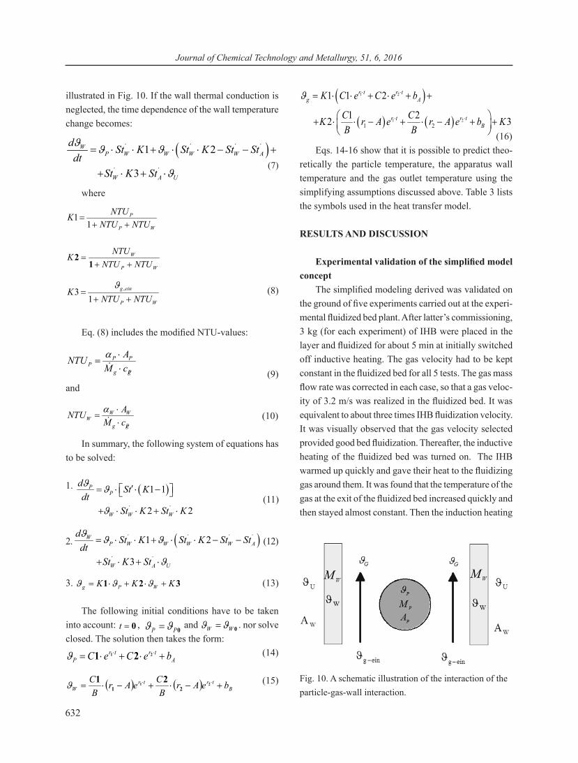
Under the simplifying assumption the gas in the fluidized bed is in contact with the particles and the ap-paratus wall, and hence with the environment. This is Fig. 8. A schematic illustration of IHB heating.
Fig. 9. A schematic illustration of apparatus’s wall heating.
Journal of Chemical Technology and Metallurgy, 51, 6, 2016
632
illustrated in Fig. 10. If the wall thermal conduction is neglected, the time dependence of the wall temperature change becomes:
( )´ ´ ´ ´
´ ´
1 2
3
WP W W W W A
W A U
d St K St K St Stdt
St K St
ϑ ϑ ϑ
ϑ
= ⋅ ⋅ + ⋅ ⋅ − − +
+ ⋅ + ⋅
(7)
where
WP
P
NTUNTUNTUK
++=
11
WP
W
NTUNTUNTU
K++
=1
2
WP
eing
NTUNTUK
++=
13 ,ϑ (8)
Eq. (8) includes the modified NTU-values:
Pgg
PPP cM
ANTU⋅⋅
=
α
(9)and
Pgg
WWW cM
ANTU⋅⋅
=
α (10)
In summary, the following system of equations has to be solved:
1. ( )´ ´
1 1
2 2
PP
W W W
d St Kdt
St K St K
ϑ ϑ
ϑ
′ = ⋅ ⋅ −
+ ⋅ ⋅ + ⋅
(11)
2. ( )´ ´ ´ ´
´ ´
1 2
3
WP W W W W A
W A U
d St K St K St Stdt
St K St
ϑ ϑ ϑ
ϑ
= ⋅ ⋅ + ⋅ ⋅ − −
+ ⋅ + ⋅
(12)
3. 321 KKK WPg +⋅+⋅= ϑϑϑ (13)
The following initial conditions have to be taken into account: 0=t ,
0PP ϑϑ = and 0WW ϑϑ = . nor solve closed. The solution then takes the form:
Atrtr
P beCeC +⋅+⋅= ⋅⋅ 21 21ϑ (14)
( ) ( ) Btrtr
W beArB
CeArB
C+−⋅+−⋅= ⋅⋅ 21
2121ϑ (15)
( )( ) ( )
1 2
1 21 2
1 1 2
1 22 3
r t r tg A
r t r tB
K C e C e b
C CK r A e r A e b KB B
ϑ ⋅ ⋅
⋅ ⋅
= ⋅ ⋅ + ⋅ + +
+ ⋅ ⋅ − + ⋅ − + +
(16)
Eqs. 14-16 show that it is possible to predict theo-retically the particle temperature, the apparatus wall temperature and the gas outlet temperature using the simplifying assumptions discussed above. Table 3 lists the symbols used in the heat transfer model.
RESULTS AND DISCUSSION
Experimental validation of the simplified model concept
The simplified modeling derived was validated on the ground of five experiments carried out at the experi-mental fluidized bed plant. After latter’s commissioning, 3 kg (for each experiment) of IHB were placed in the layer and fluidized for about 5 min at initially switched off inductive heating. The gas velocity had to be kept constant in the fluidized bed for all 5 tests. The gas mass flow rate was corrected in each case, so that a gas veloc-ity of 3.2 m/s was realized in the fluidized bed. It was equivalent to about three times IHB fluidization velocity. It was visually observed that the gas velocity selected provided good bed fluidization. Thereafter, the inductive heating of the fluidized bed was turned on. The IHB warmed up quickly and gave their heat to the fluidizing gas around them. It was found that the temperature of the gas at the exit of the fluidized bed increased quickly and then stayed almost constant. Then the induction heating
Fig. 10. A schematic illustration of the interaction of the particle-gas-wall interaction.

Vesselin Idakiev, Andreas Bück, Evangelos Tsotsas, Lothar Mörl
633
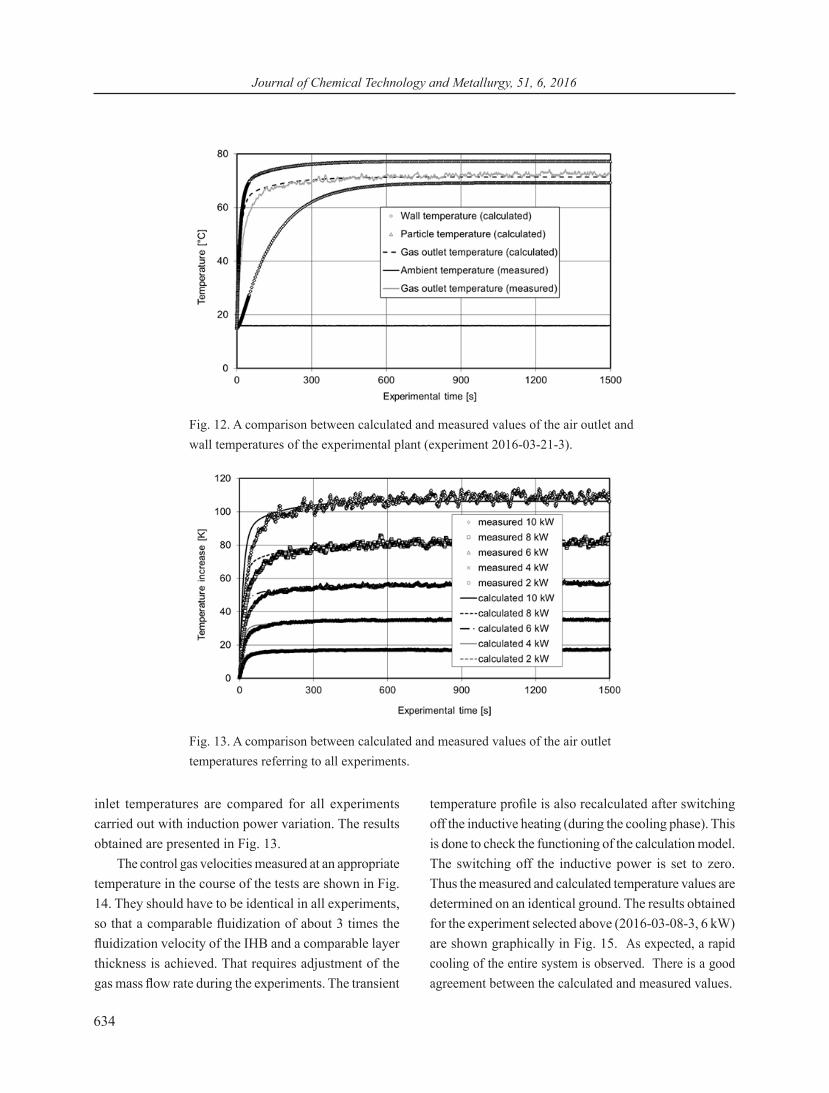
was turned off and 30 min later the outlet temperature of the gas decreased quickly as expected and approached the inlet one. After another 15 min the experiment was terminated. The temperature curves obtained in the course of experiment 3 (an inductive power of 6 kW) are shown in Fig. 11. An inductive heating efficiency of 97 % is calculated (see Table 2). In view of the simplify-ing assumptions, the model described above can predict theoretically the course of temperature of the outlet gas, of the particles and of the apparatus wall. It is worth noting that it is not possible to provide a reliable tem-
perature reading by acting both on the wall of the fluid-ized bed as well as on the particles using an alternating magnetic field. The outlet gas temperature is recorded at the temperature measuring point located on the outside apparatus wall. The value obtained is compared to the theoretically predicted one. The temperature values of the gas outlet, of the apparatus wall and of the environ-ment obtained in the course of experiment 2016-03-21-3 (6 kW) are compared to the calculated one in Fig. 12. Aiming better presentation the values of the calculated and measured differences between the gas outlet and
Experiment Diameter
IHB
Apparent density
IHB
Layer mass
IHB
Fed power
Air velocity
Air mass flow rate
Air inlet tempe- rature
Efficiency of the inductive heating
2016-03-21-1 6,75 mm 693 kg/m3 3kg 2 kW 3,2 m/s 415 kg/h
15,5 °C 98 %
2016-03-21-2 6,75 mm 693 kg/m3 3kg 4 kW 3,2 m/s 396 kg/h
15,9 °C 98 %
2016-03-21-3 6,75 mm 693 kg/m3 3kg 6 kW 3,2 m/s 369 kg/h
15,8 °C 97 %
2016-03-21-4 6,75 mm 693 kg/m3 3kg 8 kW 3,2 m/s 345 kg/h
15,8 °C 97 %
2016-03-21-5 6,75 mm 693 kg/m3 3kg 10 kW 3,2 m/s 319 kg/h
15,6 °C 98 %
Table 2. An experimental program.
Fig. 11. Time dependence of the temperature, the layer pressure loss and the air mass flow rate (experiment 2016-03-21-3).
Journal of Chemical Technology and Metallurgy, 51, 6, 2016
634
inlet temperatures are compared for all experiments carried out with induction power variation. The results obtained are presented in Fig. 13.
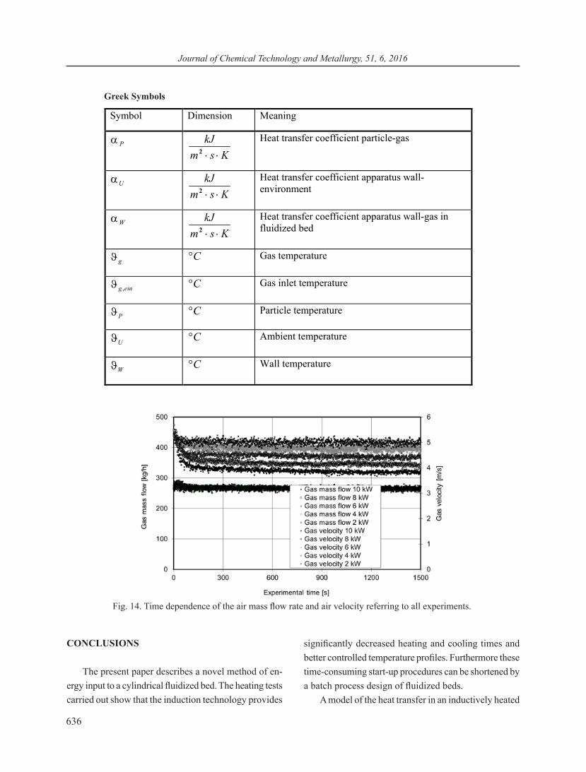
The control gas velocities measured at an appropriate temperature in the course of the tests are shown in Fig. 14. They should have to be identical in all experiments, so that a comparable fluidization of about 3 times the fluidization velocity of the IHB and a comparable layer thickness is achieved. That requires adjustment of the gas mass flow rate during the experiments. The transient
temperature profile is also recalculated after switching off the inductive heating (during the cooling phase). This is done to check the functioning of the calculation model. The switching off the inductive power is set to zero. Thus the measured and calculated temperature values are determined on an identical ground. The results obtained for the experiment selected above (2016-03-08-3, 6 kW) are shown graphically in Fig. 15. As expected, a rapid cooling of the entire system is observed. There is a good agreement between the calculated and measured values.
Fig. 12. A comparison between calculated and measured values of the air outlet and wall temperatures of the experimental plant (experiment 2016-03-21-3).
Fig. 13. A comparison between calculated and measured values of the air outlet temperatures referring to all experiments.

Vesselin Idakiev, Andreas Bück, Evangelos Tsotsas, Lothar Mörl
635
Table 3. Symbols used in the model for heat transfer calculation.
Journal of Chemical Technology and Metallurgy, 51, 6, 2016
636
CONCLUSIONS
The present paper describes a novel method of en-ergy input to a cylindrical fluidized bed. The heating tests carried out show that the induction technology provides
significantly decreased heating and cooling times and better controlled temperature profiles. Furthermore these time-consuming start-up procedures can be shortened by a batch process design of fluidized beds.
A model of the heat transfer in an inductively heated
Fig. 14. Time dependence of the air mass flow rate and air velocity referring to all experiments.
Greek Symbols
Symbol Dimension Meaning
Pα Ksm
kJ⋅⋅2
Heat transfer coefficient particle-gas
Uα Ksm
kJ⋅⋅2
Heat transfer coefficient apparatus wall-environment
Wα Ksm
kJ⋅⋅2
Heat transfer coefficient apparatus wall-gas in fluidized bed
gϑ C° Gas temperature
eing ,ϑ C° Gas inlet temperature
Pϑ C° Particle temperature
Uϑ C° Ambient temperature
Wϑ C° Wall temperature

Vesselin Idakiev, Andreas Bück, Evangelos Tsotsas, Lothar Mörl
637
cylindrical fluidized bed is developed. Its concise form is presented in this paper. It reports also a very good agreement between the model and the experiments car-ried out referring to the temperature values of the air, of the particles used and the apparatus’s wall.
The study verifies the great potential of the induc-tive energy input to fluidized beds, thereby opening up new possibilities for a product handling under precise temperature control and consistent product quality.
AcknowledgementsThe authors gratefully acknowledge the funding of
this work by the German Federal Ministry of Science and Education (BMBF) as part of the InnoProfile-Transfer project NaWiTec (grant numbers: 03IPT701A). Moreo-ver, thanks go to Nils Wonke and Robert Stiller for their contribution to the experimental work done.
REFERENCES
1. F. Winkler, Verfahren zur Herstellung von Wassergas, Patentschrift Nr.:437970, Klasse 24 e, Gruppe 1, 28.09.1922.
2. P. Feiler, Die Wirbelschicht, ein neuer Aggregatzustand, Schriftenreihe des Firmenarchivs der Badischen Anilin-& Soda-Fabrik AG, Ludwigshafen, 1972.
3. W. Michel, Wirbelschichttechnik in der Energie-wirtschaft, 1. Aufl., Dt. Verl. für Grundstoffindustrie, Leipzig, 1992.
4. J. Beranek, K. Rose, G. Winterstein, Grundlagen der Wirbelschichttechnik, VEB Deutscher Verlag für Grundstoffindustrie, Leipzig, 1975.
5. H. Martin, Berechnungsunterlagen für Druckverlust, Wärme- und Stoffübergang: Wärmeübergang in Wirbelschichten, VDI-Wärmeatlas, Mf1-Mf9.10, Springer, Berlin, 2006.
6. A. Johannsen, Wirbelschicht-Röstverfahren der Badischen Anilin- und Sodafabrik, Chemie Ingenieur Technik, 1952, 104-109.
7. H. Groenewold, E. Tsotsas, A new model for fluid bed drying, Drying Technology, 15, 6-8, 1997, 1687-1698.
8. H. Groenewold, Wirbelschichttrocknung mit in-direkter Beheizung, Dissertation an der Otto-von-Guericke-Universität Magdeburg, 2004.
9. H. Groenewold, E. Tsotsas, Experimental investiga-tion and modeling of the influence of indirect heating on fluidized bed drying, Drying Technology, 19, 8, 2001, 1739-1754.
10. L. Mörl, Anwendungsmöglichkeiten und Berech-nung von Wirbelschichtgranulations - trocknungsan-lagen, Dissertation B, TH Magdeburg, 1980.
11. H. Uhlemann, L. Mörl, Wirbelschicht-Sprühgranulation, Springer-Verl., Berlin-Heidelberg-New York, 2000.
Fig. 15. An illustration of the cooling phase - a comparison between calculated and measured parameters (experiment 2016-03-21-3).

Journal of Chemical Technology and Metallurgy, 51, 6, 2016
638
12. A. D. Salmann, M. J. Hounslow, J. P. K. Seville, Handbook of Powder Tecnology, Vol. 11 Granulation, Elsevier-Verlag, 2007.
13. C. Augustin, W. Hungerbach, Production of hollow spheres (HS) and hollow sphere structures (HSS), Mater. Lett., 63, 13–14, 2009, 1109-1112.
14. R. E. Rosensweig, Hydrocarbon conversion pro-cess utilizing a magnetic field in a fluidized bed of catalytic particles, U.S. Patent Nr. 4 136 016, 1979.
15. R. E. Rosensweig, Process for operating in magneti-cally stabilized bed, U.S. Patent Nr. 4 115 927, 1978.
16. E. J. Tuthill, Magneticallz stabilized fluidized beds, U.S. Patent Nr. 3 440 731, 1969.
17. J. Y. Hristov, Fluidization of ferromagnetic particles in a magnetic field- Part 1: The effect of field line orientation on bed stability, Powder Technol., 87, 1996, 59-66.
18. J. Y. Hristov, Fluidization of ferromagnetic par-ticles in a magnetic field- Part 2: Field effects on preliminarily gas fluidized bed, Powder Technol.,
88, 1998, 35-44. 19. A. Roßau, Induktiver Energieeintrag in eine fluid-
isierte Schüttung, Dissertation, Otto-von-Guericke-Universität Magdeburg, 2013.
20. V. V. Idakiev, A. Bück, E. Tsotsas, L. Mörl, Modellbasierte Untersuchung des Wärmeübergangs in einer induktiv beheizten Wirbelschicht, Chem. Ing. Tech., 88, 2016, 1-11.
21. V. V. Idakiev, S. Marx, A. Roßau, A. Bück, E. Tsotsas, L. Mörl, Inductive heating of fluidized beds: Influence on fluidization behavior, Powder Technology, 286, 2015, 90-97.
22. Z. B. Grbavcic, Z. L. Arsenijevic, R. V. Garic-Grulovic, Drying of Slurries in Fluidized Bed of Inert Particles, Drying Technology, 22, 8, 2004, 1793-1812.
23. A. Stresing, L. Mörl, A. Khaidurova, M. Jacob, K. Walther, Bestimmung des Zeitverhaltens einer induktiv beheizten Wirbelschicht und deren Einflussgrößen, Chemie Ingenieur Technik, 85, 3, 2013, 308-312.