INDOT Storm Water Management Field Guide · Page 4 ae aagee e e ae aagee e e Page 5 Introduction...
90
INDOT Storm Water Management Field Guide 2018
Transcript of INDOT Storm Water Management Field Guide · Page 4 ae aagee e e ae aagee e e Page 5 Introduction...
INDOTStorm WaterManagementField Guide
2018

Page 2 Page 3INDOT Storm Water Management Field Guide INDOT Storm Water Management Field Guide
TABLE OF CONTENTSINTRODUCTION ............................................................................................ 5
HOW TO USE FIELD GUIDE .................................................................... 7
PURPOSE ............................................................................................... 8
PROCESSES AND REQUIREMENTS ............................................................... 11
STORM WATER QUALITY CONTROL PLAN ............................................ 11
STORM WATER QUALITY MANAGER .................................................... 12
OTHER ENVIRONMENTAL CONSIDERATIONS ....................................... 14
STORM WATER MANAGEMENT INSPECTIONS ..................................... 17
COMMUNICATION ...................................................................................... 19
WORK MANAGEMENT ................................................................................ 20
STORM WATER MANAGEMENT ................................................................... 22
SLOPE DRAIN ....................................................................................... 24
COFFERDAM ........................................................................................ 28
PUMP AROUND ................................................................................... 32
DEWATERING ....................................................................................... 36
DIVERSION INTERCEPTORS .................................................................. 40
ROCK CHUTE ........................................................................................ 44
EROSION CONTROL .................................................................................... 49
VEGETATIVE BUFFERS .......................................................................... 50
ROUGHENING ...................................................................................... 54
TEMPORARY SEED ............................................................................... 58
TEMPORARY MULCH ........................................................................... 62
DUST CONTROL ................................................................................... 66
ROCK CHECK DAM ............................................................................... 70
TRAVERSABLE CHECK DAM .................................................................. 74
EROSION CONTROL BLANKET .............................................................. 78
PERMANENT INLET PROTECTION ........................................................ 82
PERMANENT OUTLET PROTECTION ..................................................... 86
RIPRAP DITCH ...................................................................................... 90
PERMANENT SEED ............................................................................... 94
PERMANENT SOD ................................................................................ 98
SEDIMENT CONTROL ................................................................................ 103
CONSTRUCTION ENTRANCE .............................................................. 104
SILT FENCE ......................................................................................... 108
SEDIMENT TRAP ................................................................................ 112
SEDIMENT BASIN ............................................................................... 116
FILTER BERM ...................................................................................... 120
FILTER SOCK ....................................................................................... 124
INLET PROTECTION ............................................................................ 128
CULVERT INLET PROTECTION ............................................................. 132
OTHER POLLUTION PREVENTION .............................................................. 137
TEMPORARY CROSSING ..................................................................... 138
MATERIAL STORAGE/STAGING .......................................................... 142
WASTE WATER CONTAINMENT .......................................................... 146
SUCCESSFUL STRATEGIES .......................................................................... 150
MANAGING HOT SPOTS ..................................................................... 150
NOTICE OF TERMINATION ................................................................. 160
NOTICE OF TERMINATION PROCESS FLOW CHART ............................168
DECISION MATRIX FOR STORM WATER MANAGEMENT ....................169
DEFINITIONS ...................................................................................... 174
REFERENCES AND INDOT LINKS ...............................................Back Page

Page 4 INDOT Storm Water Management Field Guide Page 5INDOT Storm Water Management Field Guide
IntroductionThe development of the Indiana Department of Transportation (INDOT) Storm Water Field Guide has been a collaborative effort between INDOT’s Office of Environmental Services, Construction Management, and District Support. The guide concept developed as a result of the Joint Transportation Research Program, Project No. C-36-68-DD, File No. 4-7-30, Indiana SPR-3312. This project also included updates to the INDOT Standard Specifications, Standard Drawings, and Design Standards.
This guide was created to provide guidance on the critical factors of management, understanding, setup, inspection, maintenance, and removal of storm water control features that may be required for INDOT contracts.
The Field Guide is not intended to act as a contract document or design standard but as a visual and conceptual reference for INDOT projects requiring storm water management. INDOT Standard Specifications and Standard Drawings are referenced throughout this guide and should be used for additional information. The Indiana Department of Environmental Management (IDEM) Storm Water Quality Manual was used as a reference in the creation of this field guide. This guide is not intended to replace IDEM’s manual but rather to enhance it and provide additional information such as photographs of Best Management Practices (BMPs) used in highway construction settings. The guide is organized with the intent of ease and efficiency of storm water management and follows a logical decision-making process. The Storm Water Field Guide begins with topics on improving communications with team members and progresses to the development of a work management plan. The logical process continues with sections describing the methods used for storm water management, erosion control, sediment control, and other pollution prevention.
The Storm Water Field Guide concludes with a section on successful strategies. This section provides tips and suggestions on managing environmental hot spots, and includes clear methodology on achieving Notice of Termination at the end of a contract. A glossary of terms and a Decision Matrix to help determine the best control measure to use for a particular problem are also included. The back page includes internet links to help further the understanding of storm water management on department contracts.
Intro
duct
ion

Page 6 INDOT Storm Water Management Field Guide Page 7INDOT Storm Water Management Field Guide
How to Use this Field Guide
This guide has been organized to provide an effective process for the use of Best Management Practices (BMPs) for effective storm water management. The process should be followed as an overall strategy leading to successful storm water management for the contract.
1. COMMUNICATION – Communicate with all members of the team. Develop a working communication plan.
2. WORK MANAGEMENT – Develop plans for effective phasing and scheduling with all team members to minimize water pollution.
3. STORM WATER MANAGEMENT – Be aware of how water moves through the job site and plan for measures to help minimize the erosive effects of water as it flows through the construction site.
4. EROSION CONTROL – Plan to keep soil in place as much as possible. Erosion control measures are relatively inexpensive and more effective than sediment control.
5. SEDIMENT CONTROL – Once soil becomes mobile, plan for BMP’s to filter and minimize the potential for sediment to leave the job site. Sediment control measures are relatively expensive to use and less effective than erosion control.
This process is one of the most efficient and cost-effective ways to manage a construction site for pollution prevention. Each chapter includes storm water features to help keep soil in place and sediment and other pollutants from leaving the job site.
The Successful Strategies section contains topics on managing hot spots, achieving Notice of Termination, a list of definitions, and a decision matrix to help the user select appropriate storm water measures to best solve a particular issue. This matrix contains a page index to guide you to the storm water feature.
Intro
duct
ion

Page 8 INDOT Storm Water Management Field Guide Page 9INDOT Storm Water Management Field Guide
PurposeRain and snow melt create storm water runoff. When precipitation falls too fast for the ground to absorb, it flows over the ground as storm water runoff. The storm water runoff picks up pollutants such as sediment and eventually flows to a stream, wetland or other water body.
Regulatory agencies do not allow sediment and other pollutants to enter water bodies or storm drains. INDOT, by law, must follow the stipulations set out by these regulatory agencies.
Stream sediment is one of the most important water quality concerns in Indiana. Muddy water kills aquatic organisms, increases the potential for flooding, and ruins wildlife habitat. Sediment laden water also carries pollutants such as heavy metals to waterways. Construction sites that are mismanaged contribute significantly more sediment pollution per acre than any other land use including agriculture. Effective storm water management on construction sites can significantly reduce storm water pollution. With numerous active construction sites throughout the state, INDOT can significantly effect Indiana’s water quality.
Important environmental resource adjacent to INDOT roadway.
Mismanagement of construction sites contributes significantly more sediment pollution per acre than agricultural activities. Source: 2007 USEPA Developing Your Stormwater Pollution Prevention Plan: A Guide for Construction Sites.
Sediment from construction site filling in a stream. This is a violation of many environmental permits.
Intro
duct
ion
Page 10 INDOT Storm Water Management Field Guide Page 11INDOT Storm Water Management Field Guide
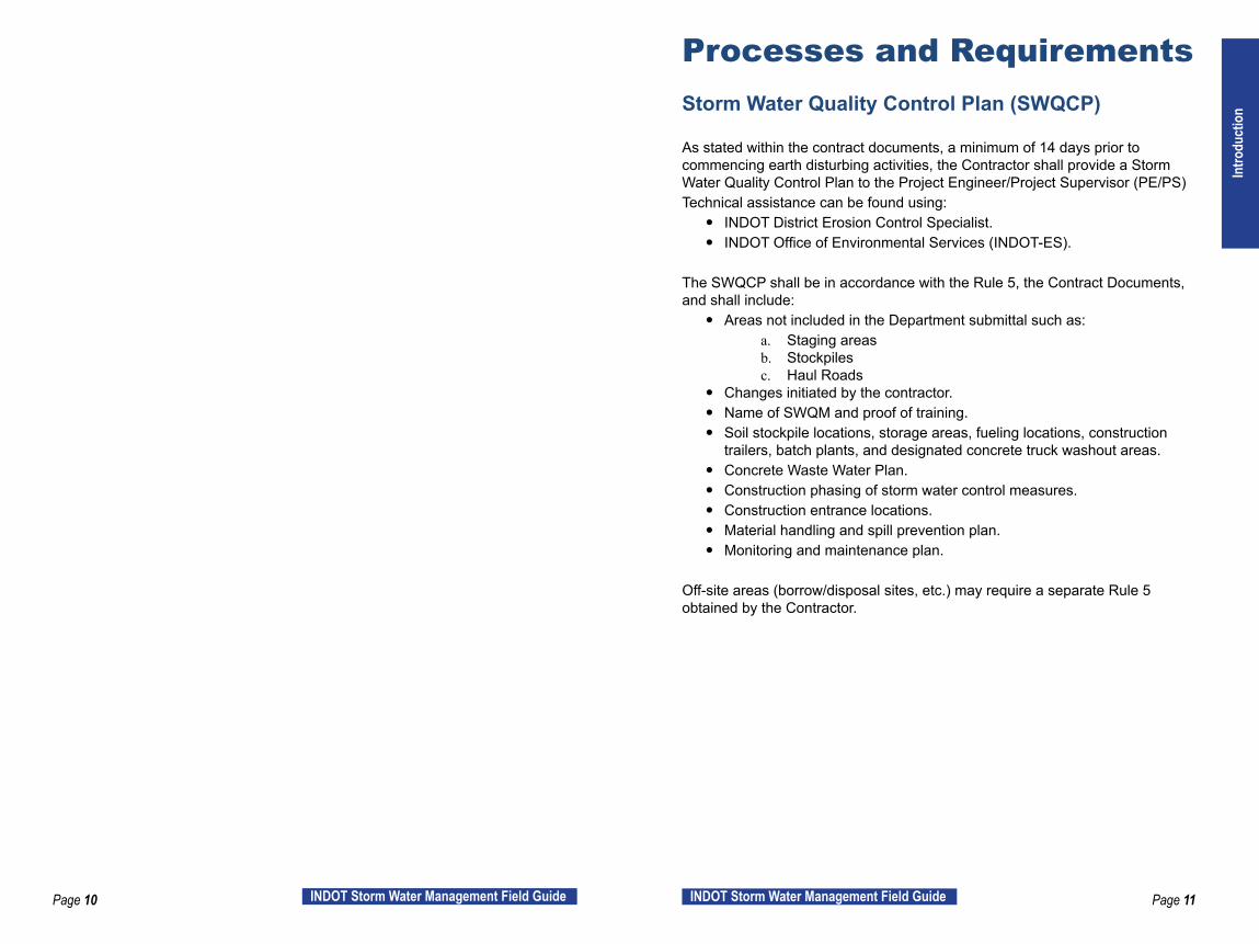
Processes and Requirements Storm Water Quality Control Plan (SWQCP)
As stated within the contract documents, a minimum of 14 days prior to commencing earth disturbing activities, the Contractor shall provide a Storm Water Quality Control Plan to the Project Engineer/Project Supervisor (PE/PS)Technical assistance can be found using:
y INDOT District Erosion Control Specialist. y INDOT Office of Environmental Services (INDOT-ES).
The SWQCP shall be in accordance with the Rule 5, the Contract Documents, and shall include:
y Areas not included in the Department submittal such as:a. Staging areasb. Stockpilesc. Haul Roads
y Changes initiated by the contractor. y Name of SWQM and proof of training. y Soil stockpile locations, storage areas, fueling locations, construction
trailers, batch plants, and designated concrete truck washout areas. y Concrete Waste Water Plan. y Construction phasing of storm water control measures. y Construction entrance locations. y Material handling and spill prevention plan. y Monitoring and maintenance plan.
Off-site areas (borrow/disposal sites, etc.) may require a separate Rule 5 obtained by the Contractor.
Intro
duct
ion

Page 12 INDOT Storm Water Management Field Guide Page 13INDOT Storm Water Management Field Guide
Storm Water Quality Manager (SWQM)
The SWQM shall be trained appropriately for the identified contract. The required level of training is identified in the Contract Information Book. Training requirements for SWQM’s are as indicated within RSP 205-R-636.
Responsibilities of the SWQM include: y Ensuring the contractor’s SWQCP has been submitted for review prior to
beginning any earth disturbing activity. y Being in responsible charge of storm water site inspections. y Being in responsible charge of implementing the SWQCP. y Being in responsible charge of BMP installation, maintenance, and
removal. y Attending the pre-construction conference. y Attending at least one contract scheduling meeting per calendar month. y Accompanying personnel from IDEM or other governmental agencies, as
required, during their site visits.
Standard ReferencesStandard Specification Reference: RSP 205-R-636
Effective storm water management can be achieved with thorough planning and proper field implementation.
Intro
duct
ion

Page 14 INDOT Storm Water Management Field Guide Page 15INDOT Storm Water Management Field Guide
Other Environmental Considerations
Jurisdictional wetlands and waterways cannot be dredged, cleared, filled, re-routed or otherwise altered without one or more permits from the US Army Corps of Engineers, IDEM and the Indiana Department of Natural Resources (IDNR) Division of Water. This includes the installation of temporary measures such as riprap, cofferdams and temporary crossings.
Keep vegetation on the banks and near jurisdictional waterways as long as possible. After work in a jurisdictional waterway is complete, the banks must be stable prior to allowing water to flow through (re-energizing) the newly constructed channel.
Non-permitted wetland impacts. Equipment tracks have altered the wetland.
Other Environmental Considerations
Environmental permit review y Locate project specific permits on the posted contract documents website. y Link all permitted impacts to plans and contact INDOT-ES with questions. y Know your permit conditions and the stream/wetland/habitat impacts. y Do not exceed your permitted impacts without consultation with
INDOT-ES. y Be familiar with all the environmental commitments for the contract.
a. Potential bat tree clearing restrictions (no clearing April 1 - September 30).
b. Potential fish spawning restrictions (no in-stream work April 1 - June 30).
c. Potential Swallow nest protection (no disturbance May 7- Sept 7).
Contractor Permit modifications and waivers y The contractor reviews permits for any modifications or waivers. y Temporary impact permits may be required for:
a. Stream crossingsb. Causewaysc. Pump-arounds
y Waivers (when applicable) may be requested for:a. Fish spawning (no in-stream work April 1 – June 30).b. Bat tree clearing (no clearing April 1 – Sept 30).c. Nesting Swallows (no disturbance May 7- Sept 7).
y Additional impacts outside of construction limits. y Communicate needs to INDOT-ES. y Allow time for processing (several weeks or longer). y Borrow/disposal areas may need separate IDEM Storm Water
Construction permit.
Intro
duct
ion

Page 16 INDOT Storm Water Management Field Guide Page 17INDOT Storm Water Management Field Guide
Storm Water Management Inspections
DescriptionConstruction sites are exposed to the weather and are continuously changing. Therefore, a proactive SWQCP and thorough site inspections are needed to minimize or eliminate the potential for storm water pollution. The inspections are a requirement to keep job sites in compliance with Rule 5. No construction site is perfect. Deficiencies are expected on these reports. The deficiencies and the measures taken to correct the problems should be documented. These reports can be used to indicate the actions taken to provide and maintain the overall quality of the storm water management plan for the site.
Standard ReferencesStandard References: RSP 205-R-636. Storm Water, Erosion, and Sediment Control Inspection form. Storm Water Quality Managers shall use the INDOT ITAP Inspection Application for all Storm Water Inspection Reports.
Expectations of the Site Inspections y All site inspections are to be under the responsible charge of the properly
trained SWQM. y Completed weekly and within 24 hours of ½” or more rain event. y Reports will be reviewed and signed by PE/PS within 24 hours of the
inspection. y Reports must be readily available. y Reports should note required maintenance, additional BMP’s needed and
progress made. y Deficiencies noted shall be addressed within 48 hours. y Inspections should be proactive. Is there a potential for storm water
pollution? y Photographs are the best method to document progress and prove efforts
toward compliance. y Inspections must continue until the Rule 5 permit is closed out with the
Notice of Termination (NOT) process.
Intro
duct
ion

Page 18 INDOT Storm Water Management Field Guide Page 19INDOT Storm Water Management Field Guide
Communication Good communication is essential to effective storm water management. No one communication plan will work for every situation and every team. Below are a few successful strategies that can be used to help prevent storm water pollution.
Successful Strategies to Save Time and Money
Communicate Early – Preconstruction Meeting y Prior to bid, the contractor should communicate with subcontractors and
suppliers about storm water quality management. y One of the best tools for saving money and using time effectively
on environmental compliance is to thoroughly discuss storm water management at the Preconstruction Meeting.
y The contractor, subcontractors, and INDOT should all be communicating storm water management issues and project phasing beginning at the Preconstruction Meeting.
Education y Prior to installing any BMP, the SWQM should communicate with the
operators and laborers on proper installation. It is more cost effective to install them correctly the first time and avoid having to repair them.
Contract Progress Meetings y SWQMs are required to attend at least one contract scheduling meeting a
month and be on the agenda each time. They shall take an active role and keep storm water management and pollution prevention as an item on the schedule.
Feedback Loop y Avoid repeat issues by ensuring there is communication with the entire
team about problems and successes.Qualified Professional
y All SWQMs shall have attended and passed INDOT’s Storm Water Quality Management Training. For level 2 projects, the SWQM shall also have a national certification in addition to INDOT training in accordance with the Specifications.
y The contractor’s SWQM should be qualified to assess the situation and provide a resolution on storm water management issues.
y The SWQM should supervise the installation of pump arounds and dewatering systems as well as be on site for major concrete pours
Team y Communication should flow in all directions. Each team member
(contractors, subcontractors, INDOT field staff, District Storm Water Specialists, etc.) should keep each other informed.
Intro
duct
ion

Page 20 INDOT Storm Water Management Field Guide Page 21INDOT Storm Water Management Field Guide
Work Management Successful Strategies to Save Time and Money
Minimize Disturbance y Managing construction operations to minimize disturbance or leave
existing vegetated areas intact as long as possible is one of the most effective ways to prevent erosion.
y Existing vegetation is approximately 97 percent effective in preventing erosion, costs nothing to install, and needs no maintenance.
Photograph courtesy of Indiana Department of Environmental Management
Save Topsoil y When removing topsoil, save it to use on slopes and ditches that will be
seeded and sodded. Protect the soil stockpile with temporary seed and mulch.
Assembly Line Grading y Plan grading operations like an assembly line, grade ditch, followed by
roughening, followed by seeding and mulching.Have a Plan “B”
y If a seeding subcontractor is not available, have an alternate plan to accomplish the work.
Work Management
Timing is Everything y Time grading operations so that any remaining permanent seeding
operations can be completed in early September. y Use weather forecasts for better pro-active storm water management. y Schedule work to ensure site is stable prior to rain events. y Seed and mulch exposed soil within seven days after earthwork operations
to prevent erosion and allow as much time as possible for vegetation growth.
Install Perimeter Protection First y Prior to any earth disturbing activities, including tree clearing, install silt
fence, filter sock, sediment traps, filter berms, construction entrances and other BMPs to prevent off-site sedimentation.
Phasing y Have a plan for each phase of construction and amend the SWQCP as
needed in response to changing site conditions.
Generally the least expensive storm water measures are the most effective. For example, limiting the amount of bare soil by phasing your project and preserving existing vegetation is less expensive and works better than installing large storm water sediment basins or ponds. Source: 2009 edition KY Erosion Prevention and Sediment Control Field Guide.
Intro
duct
ion

Page 22 INDOT Storm Water Management Field Guide Page 23INDOT Storm Water Management Field Guide
Storm Water Management Storm water flowing through disturbed areas causes erosion. Minimizing the amount of water flowing through the disturbed areas will decrease erosion.
Successful Strategies to Save Time and Money
Divert Off-Site Water y Divert off-site storm water around disturbed areas through a stabilized
channel so it does not have to be filtered. Off-site water that becomes dirty as it moves through a construction site must be filtered.
y Sediment control measures will not need to treat as much water and will require less maintenance.
Keep Water Off Slopes y Divert storm water to slope drains or rock chutes to protect slopes while
grass is getting established. y Use slope drain to extend underdrains and median drains down to the
ditch line while slopes are being stabilized.
BMPs in a Series y Rather than relying on one giant sediment control BMP at the end of the
project to collect sediment, install a series of BMPs to keep water velocity low, erosion to a minimum and reduce BMP maintenance needs.
y When used in series, sediment control devices are more efficient than when used alone.
Identify the Hot Spots y Wetlands and Streams y Karst features (Caves, sinkholes, underground streams) y Endangered species habitat y Ponds, open water y Fish, wildlife or plant resources y Long and steep slopes y Public roads y Sediment and erosion beyond project limits
Often times, hot spots are low areas or areas where storm water leaves the job site. Manage the storm water to protect them from pollution.
Storm Water Management
Multiple Storm Water BMPs working together to protect slopes and waterway.
Silt fence and mulch protecting a wetland (hot spot).
Stor
m W
ater
Man
agem
ent

Page 24 INDOT Storm Water Management Field Guide Page 25INDOT Storm Water Management Field Guide
Slope Drain
Standard ReferencesStandard Specification Reference (205-R-636): 205.05(f) Slope Drains 205.07 Maintenance
Standard Drawing Reference: 205-TECS-02, 03, 04
DescriptionSlope drains are intended to serve as an aid to reduce the erosion and sediment transfer on constructed slopes. When properly constructed, the drains will collect the runoff storm water at the surface of the slope and direct the flow through an inlet end section into a pipe to a discharge outflow area at the toe of the slope. Using a slope drain can successfully transport storm water, temporarily, from underdrains and median drains to the ditch while the slopes are being stabilized. This reduces the potential for rills and gullies on freshly graded slopes. The outflow area should be stabilized as per the Standard Drawings to further reduce sediment transferred through the construction site.
Slope Drain
Installation y Construct a temporary diversion channel (see Diversion Interceptor on
page 40) to divert runoff towards the inlet. y Lay the pipe down the slope face, connect an inlet section to the pipe at
the top of the slope, and anchor it in place. y Extend the pipe beyond the toe of the slope to a stable grade with the end
of the pipe on a riprap pad to protect the outlet from erosion. y Construct a ridge over the inlet section of pipe by placing fill over the pipe
in six-inch lifts. Do not compact with heavy equipment. y Following installation, stabilize all areas down slope of the diversion.
Inspection y Inspect weekly and within 24 hours after a ½” or more rain event. y Inspect the installation for inlet/outlet erosion problems and pipe anchoring
and leakage issues. Correct as necessary. y Inspect for gullies and other potential areas where slope drains should be
installed.
Maintenance y Check the inlet for sediment or trash accumulation; clear and restore to
proper entrance condition. y Check the fill over the pipe for settlement, cracking, or piping holes; repair
promptly. y Check pipe for evidence of leaks or inadequate anchoring; repair promptly. y Check the outlet for erosion or sedimentation; clean and repair, or extend if
necessary. y Once slopes have been stabilized, remove temporary diversions and slope
drains, and stabilize all disturbed areas.
Stor
m W
ater
Man
agem
ent
Page 26 INDOT Storm Water Management Field Guide Page 27INDOT Storm Water Management Field Guide
Slope Drain
Example Installations
Slope Drain
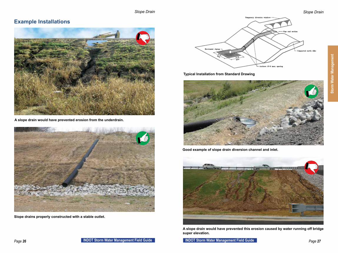
Typical Installation from Standard Drawing
Good example of slope drain diversion channel and inlet.
A slope drain would have prevented this erosion caused by water running off bridge super elevation.
A slope drain would have prevented erosion from the underdrain.
Slope drains properly constructed with a stable outlet.
Stor
m W
ater
Man
agem
ent

Page 28 INDOT Storm Water Management Field Guide Page 29INDOT Storm Water Management Field Guide
Cofferdam
Standard ReferencesStandard Specification Reference (205-R-636): 206.09 Cofferdams and Temporary Construction Dikes Standard Drawing Reference: Drawings shall be supplied by the Contractor for the specific use or are shown on the plans.
DescriptionCofferdams are temporary enclosures usually constructed within a body of water that, once built, are dewatered. Once dewatered, the cofferdam is either filled to produce a working platform or, left empty and used to construct a structural foundation within the water body limits. There are times when cofferdams can be utilized to protect an adjacent body of water closest to an active work area. The purpose for the use of cofferdams is to either isolate a jurisdictional stream or to provide a dryer area to work within and to help prevent sediment generated from the excavation/construction site from entering into the water body. Cofferdams must be constructed with materials that are impermeable and non-erodible. Cofferdams made of earth are never permitted.
Cofferdam
Installation y Ensure the proper permits, including 401/404 permits, are obtained for
use of temporary cofferdams. y Working drawings for a cofferdam installation shall be submitted by the
contractor and will provide the method of construction for details not fully shown in the plans.
y Dewatering with sediment filtering shall be used (see Dewatering on page 36).
y If concrete is being poured inside a dewatered excavation, any water that mixes with the uncured concrete shall be pumped into an approved concrete waste water containment and disposed of properly in accordance with 206.09, 702.20 (e), and RSP 205-R-636.
y Ensure all banks are stable prior to removal of cofferdams. y Remove carefully with as little disturbance as possible.
Inspection y Review all plans and working drawings for errors or omissions.
Understand what is being built. y Inspect the cofferdam installation to ensure the methods and location is
correct. y Inspect daily for leakage or bowing of the cofferdam sides. Report any
deficiencies immediately. Ensure cofferdams are not tilted or shifted. y If excessive water is entering work area, inspect for leaking areas such
as joints. y Review the location of the cofferdam. Report any movement
immediately.
Maintenance y Remediate any movement or bowing of the cofferdam body prior to re-
entry. If cofferdams have tilted or shifted, straighten as necessary and brace to prevent future movement.
y Repair any leaks to the cofferdam body in order to provide a buffer to any sediment leaving the area.
y Regrade and reseed work areas adjacent to the water bank as soon as practical prior to removal of the cofferdam.
Stor
m W
ater
Man
agem
ent
Page 30 INDOT Storm Water Management Field Guide Page 31INDOT Storm Water Management Field Guide
Cofferdam
Example Installations
Cofferdam
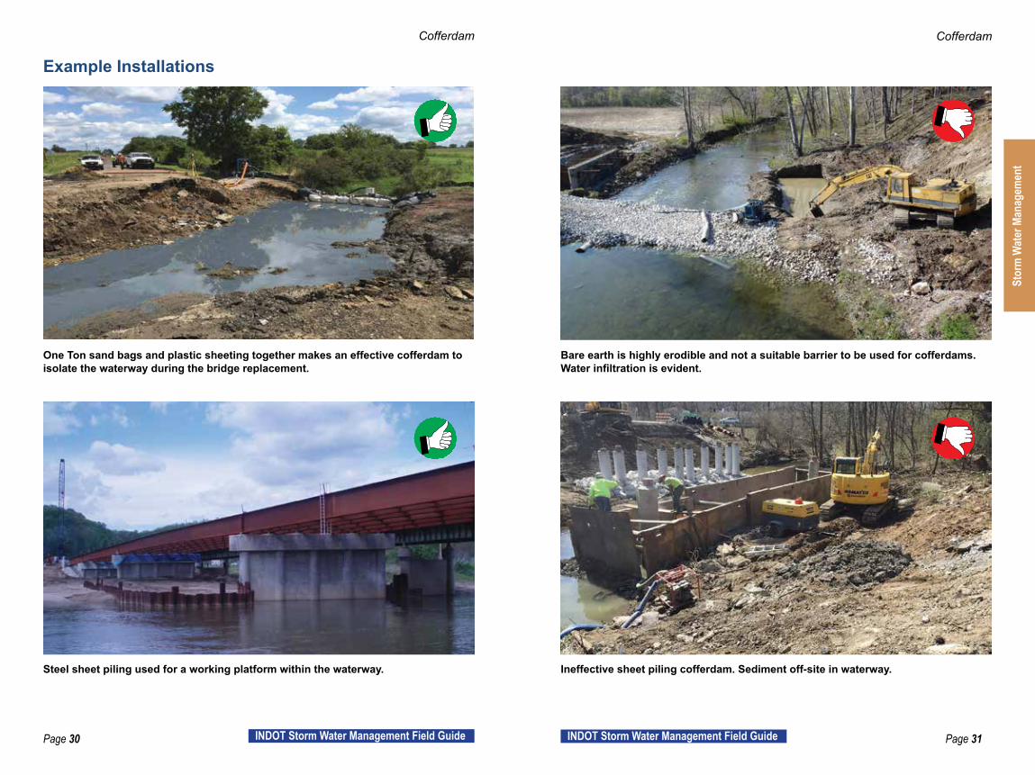
One Ton sand bags and plastic sheeting together makes an effective cofferdam to isolate the waterway during the bridge replacement.
Bare earth is highly erodible and not a suitable barrier to be used for cofferdams. Water infiltration is evident.
Steel sheet piling used for a working platform within the waterway. Ineffective sheet piling cofferdam. Sediment off-site in waterway.
Stor
m W
ater
Man
agem
ent

Page 32 INDOT Storm Water Management Field Guide Page 33INDOT Storm Water Management Field Guide
Pump Around
Standard ReferencesStandard Specification Reference: 206.09 Cofferdams and Temporary Construction Dikes Standard Drawing Reference: Details shown on plans and in environmental permits.
DescriptionA pump around should be utilized as a method of diversion for existing stream water. The purpose of the pump around is to isolate the jurisdictional water from the work area. This method of water control is usually designed specifically for a contract and will be detailed within the plans. This method may be used by a contractor in lieu of stream diversion to isolate the work area from the jurisdictional waterway. Earthen dikes are never permitted on INDOT projects.
Pump Around
Installation y Place water tight cofferdams (see Cofferdam page 28) in the waterway
both upstream and downstream of the work area. y Pump water from the upstream side, around the work area, and outlet on a
stable outlet (usually riprap) on the banks of the waterway downstream of downstream cofferdam.
y Pump should be sized to ensure upstream water does not overtop the cofferdam and allow water into the work area.
y Stream water should not be allowed to flow through work area until the area is completely stable, which includes the final shaping of the disturbed stream banks and stabilization of those banks with riprap, erosion control blankets, etc.
y Pump around stream water is not to be filtered through a filter bag.
Inspection y Inspect daily during pump around operations. y Inspect stable outlet and ensure stream bank is not eroding. y Monitor the creek water level upstream to ensure pump is adequately
sized and water does not flow over cofferdam. y Monitor the weather forecast and anticipate increases in stream water
levels.
Maintenance y Adjust outlet stabilization if bank erosion is noticed. y Adjust pump capacity as needed to handle stream water volume. y Fix leaks or otherwise stabilize cofferdams if water is back flowing into
work area.
Stor
m W
ater
Man
agem
ent

Page 34 INDOT Storm Water Management Field Guide Page 35INDOT Storm Water Management Field Guide
Pump Around
Example Installations
Pump Around
Water tight cofferdam on upstream side with adequately sized pump. Pump around was removed prior to channel bank stabilization.
Stable outlet shall not be placed in the stream channel. This is unpermitted fill and a violation of 401/404 permits.
This pump around set up is wrong. Clean water discharging directly into a stream without an energy dissipater is causing erosion.
Stor
m W
ater
Man
agem
ent
Page 36 INDOT Storm Water Management Field Guide Page 37INDOT Storm Water Management Field Guide
Dewatering
Standard ReferencesStandard Specification Reference: 206 Structure Excavation
Standard Drawing Reference: Details shown on plans and in environmental permits.
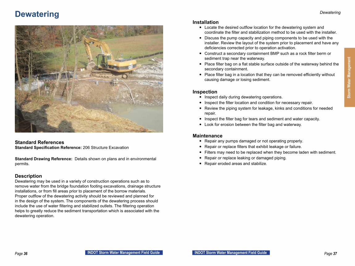
DescriptionDewatering may be used in a variety of construction operations such as to remove water from the bridge foundation footing excavations, drainage structure installations, or from fill areas prior to placement of the borrow materials. Proper outflow of the dewatering activity should be reviewed and planned for in the design of the system. The components of the dewatering process should include the use of water filtering and stabilized outlets. The filtering operation helps to greatly reduce the sediment transportation which is associated with the dewatering operation.
Dewatering
Installation y Locate the desired outflow location for the dewatering system and
coordinate the filter and stabilization method to be used with the installer. y Discuss the pump capacity and piping components to be used with the
installer. Review the layout of the system prior to placement and have any deficiencies corrected prior to operation activation.
y Construct a secondary containment BMP such as a rock filter berm or sediment trap near the waterway.
y Place filter bag on a flat stable surface outside of the waterway behind the secondary containment.
y Place filter bag in a location that they can be removed efficiently without causing damage or losing sediment.
Inspection y Inspect daily during dewatering operations. y Inspect the filter location and condition for necessary repair. y Review the piping system for leakage, kinks and conditions for needed
repair. y Inspect the filter bag for tears and sediment and water capacity. y Look for erosion between the filter bag and waterway.
Maintenance y Repair any pumps damaged or not operating properly. y Repair or replace filters that exhibit leakage or failure. y Filters may need to be replaced when they become laden with sediment. y Repair or replace leaking or damaged piping. y Repair eroded areas and stabilize.
Stor
m W
ater
Man
agem
ent

Page 38 INDOT Storm Water Management Field Guide Page 39INDOT Storm Water Management Field Guide
Dewatering
Example Installations
Dewatering
Filter bag has been placed outside construction limits and in a jurisdictional wetland. This would be considered a permit violation and cause for work stoppage and possible fines.
Filter bags should not be placed in waterways. Bags often break or become dislodged sending sediment downstream.
Good placement of cofferdam, pump around discharge and filter bag. Filter bag placed on flat surface away from sensitive environments.
Stor
m W
ater
Man
agem
ent

Page 40 INDOT Storm Water Management Field Guide Page 41INDOT Storm Water Management Field Guide
Diversion Interceptors
Standard ReferencesStandard Specification Reference (205-R-636): 205.05(c) Diversion Interceptors 205.07 Maintenance
Standard Drawing Reference: 205-TECS-01, 205-TECS-02, 205-TEC-03, 205-TECS-04
DescriptionA temporary interceptor ditch is a storm water control measure consisting of a temporary ridge, excavated channel, or combination of a channel and supporting ridge construction on a predetermined grade across a slope to collect storm water runoff and divert it to a treatment device or stable outlet. It is most commonly used with slope drains.
Slope diversion interceptors are constructed storm water control measures, consisting of a dike or dike and channel, construction along the up-slope perimeter of a disturbed slope to control storm water runoff from undisturbed areas and divert it around the construction zone.
Diversion Interceptor
Water bars are a series of small ridges or ridges and channels used to intercept and divert storm water runoff from long, narrow corridors and discharge it into a stabilized area or sediment treatment device.
Installation y Construct the diversion to dimensions and grades shown in the
construction plans or to general dimensions listed below.a. Side slopes – ratio of 2:1 or flatter (3:1 or flatter if mowed).b. Grade – positive towards outlet, but not exceeding one percent.c. Stabilize for flow.
y Construct the diversion ridge in compacted lifts. Leave enough area along the diversion to permit cleanout and re-grading.
y Stabilize interceptor ditches and slope diversions within seven days. y Stabilize diversion interceptors and outlets within seven days. The diverted
storm water flow must pass through an appropriate sediment control measure prior to leaving the construction site.
Table 1. Water Bar Spacing
Slope Spacing < 5% < 20:1 125 feet
5% to 10% 20:1 to 10:1 100 feet10% to 20% 10:1 to 5:1 75 feet20% to 33% 5:1 to 3:1 50 feet
>33% > 3:1 25 feet
Note: Diversion interceptors are also used in conjunction with temporary slope drains (Temporary Slope Drain page 24).
Inspection y Inspect weekly and within 24 hours of a ½” or more rain event. y Inspect daily if impacted by grading operations. y Inspect ridge height and valley depth. y Check outlets for needed repair.
Maintenance y Remove sediment from channel to maintain positive grade. y Adjust ridge height to prevent overtopping. y Make necessary repairs immediately to outlets. y Stabilize areas that are eroding. y Reform diversion interceptors as needed if disturbed by grading
operations.
Stor
m W
ater
Man
agem
ent

Page 42 INDOT Storm Water Management Field Guide Page 43INDOT Storm Water Management Field Guide
Diversion Interceptor
Diversion Interceptor
Diversion interceptor directing water to a filter berm.
Schematic of diversion interceptor concept. IDEM Indiana Storm Water Quality Manual.
Stable diversion interceptor around a box culver installation. Diverted stream water should flow freely. Riprap should not be placed in channel.
Example of permanent diversion interceptor installation.
Example Installations
Stor
m W
ater
Man
agem
ent

Page 44 INDOT Storm Water Management Field Guide Page 45INDOT Storm Water Management Field Guide
Rock Chute
Standard ReferencesStandard Specification Reference: 616.01-08 Riprap, 616.10-11 Geotextiles
Standard Drawing Reference: Rock Chute details shown in plans
DescriptionA rock lined chute is a water conveyance consisting of a lined channel used to move water down a slope in a non-erosive manner. Its main purpose is to reduce channel flow velocity, increase energy dissipation, and provide a stable grade at the outlet to prevent erosion. Riprap is used to stabilize a channel but should not be used to collect sediment.
Rock Chute
Installation y Excavate and compact the channel prior to placement of geotextile.
Construct the channel excavation with a swale depression through the length of the channel for flow direction. Riprap is recommended to be placed at a depth of twice the stone diameter or 12 inches, whichever is greater.
y Place geotextiles on the compacted, relatively smooth surface. Overlap geotextile sheets 18” with the upstream sheet over the downstream sheet. Blend the lining material into the surrounding grade.
y Chute must be cut to final cross section/grade in a concave shape. Water shall be directed to flow down the middle of the rock chute and not along the sides causing erosion.
Inspection y Inspect weekly and within 24 hours of a ½” or more rain event. y Inspect channel geotextiles and lining materials for gaps, breaks, or
washouts for necessary repairs. y Inspect for any undermining of the channel and repair as needed. y Look for any rills that may begin to form due to washouts or undermining
and repair promptly. y Inspect for sediment collecting in the riprap.
Maintenance y If scour is found along the sides of the chute, reshape chute as needed for
water to flow through the riprap. y Promptly repair and reseed/mulch any small rills that form. y Repair or replace any breaks, gaps, washouts or damage in the geotextile
or the channel lining material. y If sediment is found in the riprap, stabilize slopes and areas upstream of
channel. Clean out or replace riprap. y If scour is found downstream of the chute, additional riprap may be
needed. Consult with designer and/or Environmental Services to ensure no permits or permit modifications are needed.
Stor
m W
ater
Man
agem
ent

Page 46 INDOT Storm Water Management Field Guide Page 47INDOT Storm Water Management Field Guide
Rock Chute Rock Chute
Good example of placement of a rock chute to help with runoff from an adjacent farm field.
Rock chute installed without proper swale depression causing erosion rills.
Water is bypassing rock chute. Riprap turnout details can be found in the plans with the miscellaneous details.
Example Installations
Stor
m W
ater
Man
agem
ent

Page 48 INDOT Storm Water Management Field Guide Page 49INDOT Storm Water Management Field Guide
Erosion ControlErosion control involves maintaining the soil on the ground, within the construction area, and minimizing its movement. Preventing erosion is more efficient and cost effective than managing sediment after it begins to be transported by storm water. Keeping soil in its place with well managed erosion control, minimizes the need for sediment control BMPs, reduces maintenance on those BMPs, and lowers costs of regrading.
Successful Strategies to Save Time and Money
Minimize Disturbance y Preserve as much existing vegetation for as long as possible. y Work that exposes bare soil and is scheduled to be inactive for more than
seven days, shall have mulch and seed applied to the area. y Limit disturbance through thoughtful phasing/sequencing of construction
activities.
Protect the Soil y Permanent seed as soon as possible y Seeding and mulching are the least expensive and most effective erosion
control measures. y Erosion control blankets can also be used for temporary stabilization for
bare or exposed areas. Blankets are very effective on long steep slopes.
Eros
ion
Cont
rol

Page 50 INDOT Storm Water Management Field Guide Page 51INDOT Storm Water Management Field Guide
Vegetative Buffers
Standard ReferencesStandard Specification Reference (205-R-636): 205.05(g) Vegetative Filter Strips 205.07 Maintenance
Standard Drawing Reference: N/A
DescriptionGrass, shrubs, trees and other vegetation located above or below excavated areas should be preserved if possible. A vegetative buffer located above a construction site reduces water runoff velocity. Vegetative buffers located below construction site activity helps trap and filter sediment before it can move into ditches, channels and streams. All vegetated areas help to promote infiltration of storm water, which is a key objective in preventing erosion and controlling sediment movement off the construction site. Flat areas with sheet flow are a more effective buffer than steep areas or areas of concentrated flow.
Vegetative Buffers
Installation y Evaluate existing vegetation and determine if it will serve as a filter strip
(weeds are not an acceptable vegetative filter). Look for areas where vegetation is at least four inches high and cover 80 percent or more of the soil surface.
y If existing vegetation is not adequate, and if site conditions and seeding conditions are favorable, overseed the area or fertilize the existing vegetation to enhance growth and density. Allow time for sufficient vegetative growth before discharging sediment-laden storm water runoff into the filter strip.
y Never use wetlands as a vegetative filter. Water should be filtered prior to entering wetlands.
Inspection y Inspect weekly and within 24 hours after a ½” or more rain event. y Inspect for the beginning of erosion rills or channel erosion. y Inspect for accumulated areas of sediment.
Maintenance y Promptly repair any small rills that form. y Add fertilizer and soil amendments as needed to maintain healthy
vegetation. y Mow as needed but not shorter than four inches. y Where the filter strip has actively trapped sediment during construction,
remove the accumulated sediment, regrade the area and reseed it when conditions are favorable for vegetative establishment.
Eros
ion
Cont
rol

Page 52 INDOT Storm Water Management Field Guide Page 53INDOT Storm Water Management Field Guide
Vegetative Buffers Vegetative Buffers
Narrow strip of vegetation on the bank is only partially protecting the stream. Note the sediment entering the waterway.
Good example of vegetative filter strip (and silt fence) protecting the waterway from sediment.
Existing vegetative buffer along and within the ditch.U.S. Department of Agriculture. Conservation Buffers: Design Guidelines for Buffers, Corridors, and Greenways. General Technical Reports SRS-109 September 2008.
Example Installations
4” Minimum Height
Ditch Flowline
Vegetative Buffer Strip Pavement Shoulder
Vegetative buffer helps trap and filter sediment before it enters ditch flowline.
Eros
ion
Cont
rol

Page 54 INDOT Storm Water Management Field Guide Page 55INDOT Storm Water Management Field Guide
Roughening
Standard ReferencesStandard Specification Reference: 203.09 General Requirements 205.07 Maintenance
Standard Drawing Reference: N/A
DescriptionSurface roughening (or tracking), is the creation of ridges and depressions parallel to the contour of the slope to reduce runoff velocity and increase infiltration. A bulldozer track mark creates small ridges and valleys which help trap sediment and aid in establishment of vegetation. The track marks help to reduce the eroding effect of rain water as that water hits and travels down the slope. Without these track marks, and their roughening effect on the bare soil, the slope’s resistance to erosion is greatly reduced.
Roughening
Installation y All slopes shall be roughened until permanent erosion control measures
are placed. Roughening shall take place each day after work is performed on the slopes, or as directed to re-establish the roughening.
y Slopes shall be roughened to create a series of ridges and depressions parallel to the contour making grooves at least 1” deep and not more than 15” apart.
y Discuss the operation of roughening with the Storm Water Management Team to ensure understanding of the operation.
Inspection y Inspect weekly and within 24 hours after a ½” or more rain event. y Ensure that the ridges and depressions created by the track marks are in a
horizontal direction and parallel to the contour of the slope. y Check for rills and gullies.
Maintenance y Promptly repair any small rills that form and re-roughen the repaired area
when directed or required. y As soon as possible, reinforce the slope roughening with an appropriate
erosion control measure such as seeding and mulching. Eros
ion
Cont
rol

Page 56 INDOT Storm Water Management Field Guide Page 57INDOT Storm Water Management Field Guide
Roughening Roughening
Vertical track marks will contribute to rill erosion. Horizontal track marks create small ridges and valleys to trap seed and mulch and help stabilize a slope.
Operate bulldozer or other tracked vehicle up and down slopes before seeding to create tread-track depressions for catching and holding seed.
Vertical track marks make erosion worse and creates a series of rills to quickly move water and sediment to the ditch bottom.
Example Installations
Eros
ion
Cont
rol
Page 58 INDOT Storm Water Management Field Guide Page 59INDOT Storm Water Management Field Guide
Temporary Seed
Standard ReferencesStandard Specification Reference: 205.04(a) Seed 205.07 Maintenance
Standard Drawing Reference: N/A
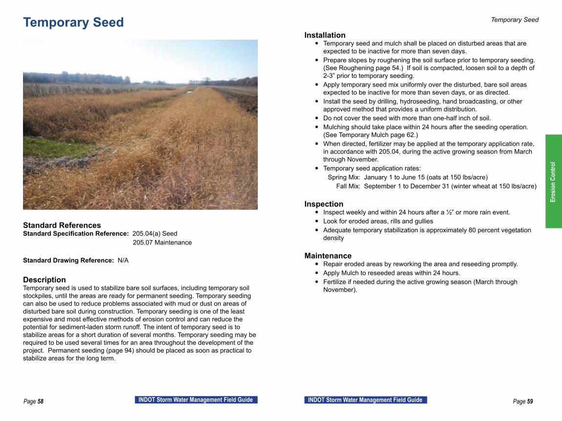
DescriptionTemporary seed is used to stabilize bare soil surfaces, including temporary soil stockpiles, until the areas are ready for permanent seeding. Temporary seeding can also be used to reduce problems associated with mud or dust on areas of disturbed bare soil during construction. Temporary seeding is one of the least expensive and most effective methods of erosion control and can reduce the potential for sediment-laden storm runoff. The intent of temporary seed is to stabilize areas for a short duration of several months. Temporary seeding may be required to be used several times for an area throughout the development of the project. Permanent seeding (page 94) should be placed as soon as practical to stabilize areas for the long term.
Temporary Seed
Installation y Temporary seed and mulch shall be placed on disturbed areas that are
expected to be inactive for more than seven days. y Prepare slopes by roughening the soil surface prior to temporary seeding.
(See Roughening page 54.) If soil is compacted, loosen soil to a depth of 2-3” prior to temporary seeding.
y Apply temporary seed mix uniformly over the disturbed, bare soil areas expected to be inactive for more than seven days, or as directed.
y Install the seed by drilling, hydroseeding, hand broadcasting, or other approved method that provides a uniform distribution.
y Do not cover the seed with more than one-half inch of soil. y Mulching should take place within 24 hours after the seeding operation.
(See Temporary Mulch page 62.) y When directed, fertilizer may be applied at the temporary application rate,
in accordance with 205.04, during the active growing season from March through November.
y Temporary seed application rates: Spring Mix: January 1 to June 15 (oats at 150 lbs/acre) Fall Mix: September 1 to December 31 (winter wheat at 150 lbs/acre)
Inspection y Inspect weekly and within 24 hours after a ½” or more rain event. y Look for eroded areas, rills and gullies y Adequate temporary stabilization is approximately 80 percent vegetation
density
Maintenance y Repair eroded areas by reworking the area and reseeding promptly. y Apply Mulch to reseeded areas within 24 hours. y Fertilize if needed during the active growing season (March through
November).
Eros
ion
Cont
rol

Page 60 INDOT Storm Water Management Field Guide Page 61INDOT Storm Water Management Field Guide
Temporary Seed Temporary Seed
Weeds indicate slope has been unprotected for an extended amount of time. Temporary seed and mulch should have been applied within seven days of inactivity.
Early stages of temporary vegetation providing slope stability.
Temporary vegetation and slope drains providing slope stability. Temporary seeding on long steep slope requires maintenance. Notice the beginning of rills.
Example Installations
Eros
ion
Cont
rol
Page 62 INDOT Storm Water Management Field Guide Page 63INDOT Storm Water Management Field Guide
Temporary Mulch
Standard ReferencesStandard Specification Reference: 205.04(b) Mulch 205.07 Maintenance
Standard Drawing Reference: N/A
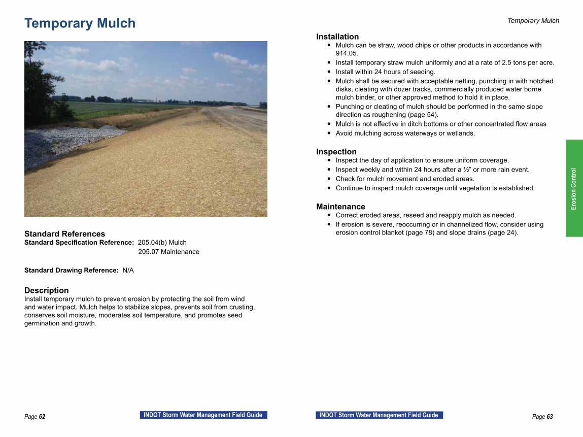
DescriptionInstall temporary mulch to prevent erosion by protecting the soil from wind and water impact. Mulch helps to stabilize slopes, prevents soil from crusting, conserves soil moisture, moderates soil temperature, and promotes seed germination and growth.
Temporary Mulch
Installation y Mulch can be straw, wood chips or other products in accordance with
914.05. y Install temporary straw mulch uniformly and at a rate of 2.5 tons per acre. y Install within 24 hours of seeding. y Mulch shall be secured with acceptable netting, punching in with notched
disks, cleating with dozer tracks, commercially produced water borne mulch binder, or other approved method to hold it in place.
y Punching or cleating of mulch should be performed in the same slope direction as roughening (page 54).
y Mulch is not effective in ditch bottoms or other concentrated flow areas y Avoid mulching across waterways or wetlands.
Inspection y Inspect the day of application to ensure uniform coverage. y Inspect weekly and within 24 hours after a ½” or more rain event. y Check for mulch movement and eroded areas. y Continue to inspect mulch coverage until vegetation is established.
Maintenance y Correct eroded areas, reseed and reapply mulch as needed. y If erosion is severe, reoccurring or in channelized flow, consider using
erosion control blanket (page 78) and slope drains (page 24).
Eros
ion
Cont
rol

Page 64 INDOT Storm Water Management Field Guide Page 65INDOT Storm Water Management Field Guide
Temporary Mulch Temporary Mulch
Temporary mulch applied too thin. Slope lacks erosion protection. Mulch and seed application rate should be per Specification.
Wood chips from tree clearing used as erosion control for sheet flow area.
Mulch applied adequately and uniformly. Stockpiled soil protected with mulch.
Example Installations
Eros
ion
Cont
rol

Page 66 INDOT Storm Water Management Field Guide Page 67INDOT Storm Water Management Field Guide
Dust Control
Standard ReferencesStandard Specification Reference: 107.08 (b) Dust and Air Pollution Standard Drawing Reference: N/A
DescriptionDust control, especially during hot and dry conditions, helps reduce wind erosion. Methods can include watering, resin/polymer application (in accordance with local, state, and federal regulations), mulching, street sweeping, and temporary vegetative covers. A pro-active approach should be used for effective dust control.
Dust Control
Installation y The contractor and INDOT’s PE/PS should discuss the location of haul
roads at the pre-construction meeting to determine the best method to utilize for dust control. If possible, locate haul roads away from residential, commercial or other public areas.
y Apply water at a rate to keep soil wet/moist, but not saturated or muddy. y If sweeping is a chosen method, wet the area with water prior to the
sweeping operation to aid in dust suppression.
Inspection y Be aware of the potential for dust as the season progresses and keep
discussions on the issue open between the SWQM and INDOT’s PE/PS. y Inspect as needed, daily during hot and dry seasons. Be proactive. Stay
ahead of the issue.
Maintenance y Apply additional water or mulch as needed to control dust. Repetition is
required for effective control. y Keep construction equipment speeds appropriate for the conditions. y Stabilize disturbed areas with vegetation and mulch as much as possible.
Eros
ion
Cont
rol

Page 68 INDOT Storm Water Management Field Guide Page 69INDOT Storm Water Management Field Guide
Dust Control Dust Control
Dust contributes to air pollution, can interfere with drainage and can create traffic hazards.
Covering exposed soil with mulch is an effective dust control practice.
Sweeping paved surfaces reduces dust from vehicles. Temporary seed or permanent seed as early as possible to reduce dust on a construction site.
Example Installations
Eros
ion
Cont
rol

Page 70 INDOT Storm Water Management Field Guide Page 71INDOT Storm Water Management Field Guide
Rock Check Dam
Standard ReferencesStandard Specification Reference: 205.05(a) Check Dam 205.07(g) Maintenance
Standard Drawing Reference: E 205-TECD-01
DescriptionA rock check dam consists of geotextile fabric and aggregate, placed across drainage channels to slow storm water runoff. This measure is primarily to prevent channel erosion in roadside ditches but may also provide limited sediment control. Rock check dams should not be used as a substitute for other erosion control BMPs (seed and mulch) and sediment control BMPs (sediment traps).
IDEM requires that one-quarter of the total check dams on INDOT projects be Modified Check Dams. Modified check dams have filter stone all the way up the face of the dam. These modified check dams should be placed closest to a sediment control BMP or stream/wetland.
Rock Check Dam
Installation y Discuss with team members and identify the areas for rock check dam
installation. y Install check dams so that 25 percent are modified check dams. y Place revetment riprap on geotextile fabric that extends downstream of
check dam. y Include #5 or #8 filter stone on upstream side. y The weir (lowest part of the dam) should be in the middle with the sides
tied into the slopes. (Like a smile ) y Space check dams so that the bottom of the upstream dam should align
with the weir of the downstream dam.
Inspection y Inspect weekly and within 24 hours after a ½” or more rain event. y Check to make sure center of the dam is low and the sides are tied into the
slopes so water flows across center of dam. Check dam should resemble a smile.
y Check for #5 or #8 filter stone on front face of dam. y Geotextile under dam should extend 3 feet down the slope. y Inspect for channel erosion. If channel erosion is found, space check dams
closer so that the bottom of the upstream dam is aligned with the weir of the downstream dam.
Maintenance y Remove sediment once it reaches one-half the height of the check dam. y Repair or replace if the check dam is damaged or ineffective.
INDOT Standard Drawing, Temporary Check Dam, Revetment Riprap.
Eros
ion
Cont
rol

Page 72 INDOT Storm Water Management Field Guide Page 73INDOT Storm Water Management Field Guide
Rock Check Dam Rock Check Dam
Check dam is much bigger than necessary. Wasted material, wasted money, cancause flooding, and will be much more difficult to remove.
Check dam shaped correctly with low weir in the middle and tied into the slopes.
Check dam not shaped correctly causing water to bypass dam and erode slopes. Rock check dam not built to specification. Not shaped correctly, no filter stone, no geotextile. The check dam should be rebuilt.
Example Installations
Eros
ion
Cont
rol
Page 74 INDOT Storm Water Management Field Guide Page 75INDOT Storm Water Management Field Guide
Traversable Check Dam
Standard ReferencesStandard Specification Reference: 205.05(b) Check Dam, Traversable 205.07(g) Maintenance
Standard Drawing Reference: E 205-TECD-02
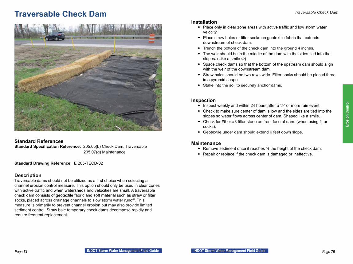
DescriptionTraversable dams should not be utilized as a first choice when selecting a channel erosion control measure. This option should only be used in clear zones with active traffic and when watersheds and velocities are small. A traversable check dam consists of geotextile fabric and soft material such as straw or filter socks, placed across drainage channels to slow storm water runoff. This measure is primarily to prevent channel erosion but may also provide limited sediment control. Straw bale temporary check dams decompose rapidly and require frequent replacement.
Traversable Check Dam
Installation y Place only in clear zone areas with active traffic and low storm water
velocity. y Place straw bales or filter socks on geotextile fabric that extends
downstream of check dam. y Trench the bottom of the check dam into the ground 4 inches. y The weir should be in the middle of the dam with the sides tied into the
slopes. (Like a smile ) y Space check dams so that the bottom of the upstream dam should align
with the weir of the downstream dam. y Straw bales should be two rows wide. Filter socks should be placed three
in a pyramid shape. y Stake into the soil to securely anchor dams.
Inspection y Inspect weekly and within 24 hours after a ½” or more rain event. y Check to make sure center of dam is low and the sides are tied into the
slopes so water flows across center of dam. Shaped like a smile. y Check for #5 or #8 filter stone on front face of dam. (when using filter
socks). y Geotextile under dam should extend 6 feet down slope.
Maintenance y Remove sediment once it reaches ½ the height of the check dam. y Repair or replace if the check dam is damaged or ineffective.
Eros
ion
Cont
rol

Page 76 INDOT Storm Water Management Field Guide Page 77INDOT Storm Water Management Field Guide
Traversable Check Dam Traversable Check Dam
INDOT Standard Drawing of filter socks used as an alternative to straw bales. Installation should include three filter socks in a pyramid with geotextile underneath.
Straw bale check dams undermined due to high velocities, no geotextile and no trenching.
The water volume and velocity in this area are too much for traversable check dams. There should be more focus on erosion control with seed, mulch and erosion control blanket.
Straw bales should be two wide along the ground, not two high.
Example Installations
Eros
ion
Cont
rol

Page 78 INDOT Storm Water Management Field Guide Page 79INDOT Storm Water Management Field Guide
Erosion Control Blanket
Standard ReferencesStandard Specification Reference (205-R-630): 205.04 (c) Temporary Surface Stabilization
Standard Specification Reference: N/A
DescriptionErosion control blankets are a manufactured surface protection product. They act as a specialized mulching material and are normally used on long or steep slopes and in concentrated flow channels. The advantages that erosion control blankets provide include preventing erosion by protecting the soil from rainfall impact, overland water flow, concentrated runoff, or wind. The blankets are also anchored to help in the most critical areas. Blankets tend to conserve moisture and increase seed germination and seedling growth.
Erosion Control Blanket
Installation y Select the appropriate type of blanket needed specifically for the
designated area and anticipated water velocity. y The area shall be relatively free of all rocks or clods over 1½” in diameter y Lay erosion control blankets on the seeded area so that they are parallel
to the primary direction of water flow, in continuous contact with the soil, and with each upstream blanket overlapping the downstream blanket.
y Tuck the uppermost edge of the upper blankets into a check slot, backfill with soil and tamp down.
y Anchor the blankets in place by driving staples, pins, or stakes through the blanket and into the underlying soil.
Inspection y Check for erosion or displacement of the blanket weekly and within 24
hours of a ½” or more rain. y Blanket needs to be anchored and overlapped properly according to
specification to ensure proper function.
Maintenance y If any area shows erosion, pull back that portion of the blanket covering
the eroded area, add soil and tamp, reseed the area, replace and staple the blanket.
Eros
ion
Cont
rol

Page 80 INDOT Storm Water Management Field Guide Page 81INDOT Storm Water Management Field Guide
Erosion Control Blanket Erosion Control Blanket
Ditches without blankets will wash the mulch away, disabling grass from growing and leading to erosion.
Erosion control blankets will not work if proper soil grading is not completed first. Blankets not installed parallel to direction of water flow.
Erosion Control Blanket being used for permanent vegetation establishment and slope protection.
Blankets can be used as temporary or permanent erosion control around hot spots such as creek banks.
Example Installations
Eros
ion
Cont
rol

Page 82 INDOT Storm Water Management Field Guide Page 83INDOT Storm Water Management Field Guide
Permanent Inlet Protection
Standard ReferencesStandard Specification Reference: 616.05 Riprap 616.11 Geotextile under riprap
Standard Drawing Reference: N/A – Contract Specific Design
DescriptionThe inlet protection is described as the permanent protection of the upstream side of culverts and pipes. Channel flow upon approaching a structure, pipe or culvert will constrict and increase velocity having to enter a smaller cross- sectional area. This increased velocity can cause erosion around the structure inlet. Typically, riprap is used on the upstream part of the structure to armor the areas affected by the increased velocity of the water flow.
Permanent Inlet Protection
Installation y Geotextile must be laid out according to the plans and details. Geotextiles
should cover the bottom of the channel and at least halfway up the side slopes of the channel.
y Geotextile must be placed under all the intended areas for riprap. The geotextiles shall be placed on a relatively smooth grade free of obstructions, depressions, and debris.
y Place riprap on geotextile at the depth shown on the plan and matching the plan location and grade.
Inspection y Inspect weekly and within 24 hours of a ½” or more rain event. y Ensure that the geotextile has been handled and placed according to
specification. y All riprap shall be placed on top of installed geotextile. y Inspect for scour around the inlet and beyond the limits of the riprap.
Maintenance y Promptly repair any erosion that forms. y Replace geotextile if it has been damaged. y Clean out or replace any riprap showing excessive sediment build-up.
Eros
ion
Cont
rol

Page 84 INDOT Storm Water Management Field Guide Page 85INDOT Storm Water Management Field Guide
Permanent Inlet Protection Permanent Inlet Protection
The lack of permanent protection has caused scouring around pipe inlet. Permanent inlet protection without geotextile fabric and haphazard placement.
Pipe does not need riprap for permanent inlet protection because permanent vegetation was established for stabilization and velocity is low.
Permanent inlet protection includes wing walls and riprap protection.
Example Installations
Eros
ion
Cont
rol
Page 86 INDOT Storm Water Management Field Guide Page 87INDOT Storm Water Management Field Guide
Permanent Outlet Protection
Standard ReferencesStandard Specification Reference: 616.05 Riprap 616.11 Geotextile under riprap Standard Drawing Reference: N/A – Contract Specific Design
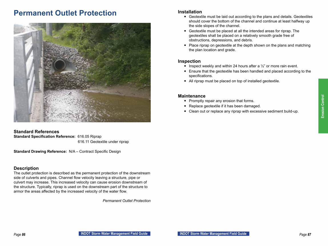
DescriptionThe outlet protection is described as the permanent protection of the downstream side of culverts and pipes. Channel flow velocity leaving a structure, pipe or culvert may increase. This increased velocity can cause erosion downstream of the structure. Typically, riprap is used on the downstream part of the structure to armor the areas affected by the increased velocity of the water flow.
Permanent Outlet Protection
Installation y Geotextile must be laid out according to the plans and details. Geotextiles
should cover the bottom of the channel and continue at least halfway up the side slopes of the channel.
y Geotextile must be placed at all the intended areas for riprap. The geotextiles shall be placed on a relatively smooth grade free of obstructions, depressions, and debris.
y Place riprap on geotextile at the depth shown on the plans and matching the plan location and grade.
Inspection y Inspect weekly and within 24 hours after a ½” or more rain event. y Ensure that the geotextile has been handled and placed according to the
specifications. y All riprap must be placed on top of installed geotextile.
Maintenance y Promptly repair any erosion that forms. y Replace geotextile if it has been damaged. y Clean out or replace any riprap with excessive sediment build-up.
Eros
ion
Cont
rol

Page 88 INDOT Storm Water Management Field Guide Page 89INDOT Storm Water Management Field Guide
Permanent Outlet Protection Permanent Outlet Protection
Too much riprap has been placed within the channel. Riprap should be sumped to allow the waterway and box culvert to naturally fill with sediment over time and form a new channel above the riprap. Refer to and follow the IDEM 401 and USACE 404 permit conditions.
Outlet protection not shaped correctly. Water should flow down the middle of the riprap.
Ditch is properly sumped to create a natural flow line to eliminate erosion. Outlet protection slows the velocity of water exiting the pipe to help prevent erosion.
Example Installations
Eros
ion
Cont
rol

Page 90 INDOT Storm Water Management Field Guide Page 91INDOT Storm Water Management Field Guide
Riprap Ditch
Standard ReferencesStandard Specification Reference: 616.01-08 Riprap, 616.10-11 Geotextiles
Standard Drawing Reference: N/A – Contract Specific Design
DescriptionRiprap is used as a means to slow the velocity and dissipate the energy of water in concentrated or channel flow to prevent channel erosion. Stone should be extended far enough up the slope to prevent scouring at the edge of the riprap. A riprap ditch is often placed where water volume or velocity is too high to establish adequate permanent vegetation. Riprap is used to stabilize and armor a channel but should not be used to collect sediment. Geotextile should always be placed under the riprap.
Riprap Ditch
Installation y Ditch must be cut to final cross section/grade. y Place geotextile on a relatively even surface. Overlap geotextile sheets 18
inches with the upstream sheet over the downstream sheet. y Riprap must be placed at the specified thickness shown on the plans. y Top of riprap must match the cross section grade. The finished surface
shall vary no more than 9 inches from a true plane.
Inspection y Inspect weekly and within 24 hours after a ½” or more rain event. y Verify riprap is was placed in the correct location and quantity shown in the
plans and standard specifications. y Inspect for scour along the sides of and downstream of riprap channel. y Inspect for sediment collecting in the riprap channel.
Maintenance y If sediment is found in the riprap, stabilize slopes and areas upstream of
channel. Clean out or replace riprap. y If scour is found along the sides of the channel, reshape channel as
needed for water to flow through the riprap. y If scour is found downstream of the channel, additional riprap may be
needed. Consult with designer and/or Environmental Services to ensure no permits or permit modifications are needed. Repair any damaged geotextiles.
Eros
ion
Cont
rol
Page 92 INDOT Storm Water Management Field Guide Page 93INDOT Storm Water Management Field Guide
Riprap Ditch Riprap Ditch
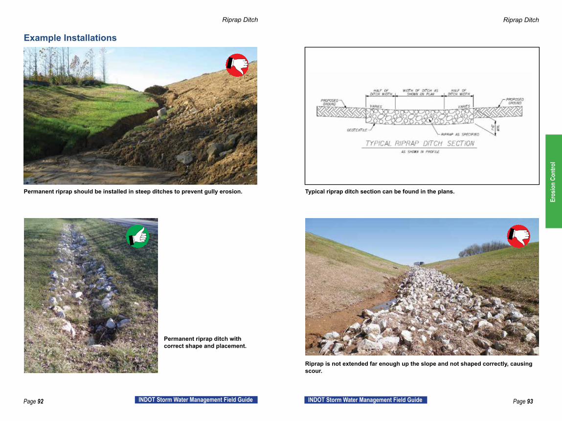
Permanent riprap should be installed in steep ditches to prevent gully erosion. Typical riprap ditch section can be found in the plans.
Permanent riprap ditch with correct shape and placement.
Riprap is not extended far enough up the slope and not shaped correctly, causing scour.
Example Installations
Eros
ion
Cont
rol
Page 94 INDOT Storm Water Management Field Guide Page 95INDOT Storm Water Management Field Guide
Permanent Seed
Standard ReferencesStandard Specification Reference: 621 Seeding and Sodding RSP 629-R-630 Plant Growth Layer 914 Roadside Development Materials
Standard Drawing Reference: N/A
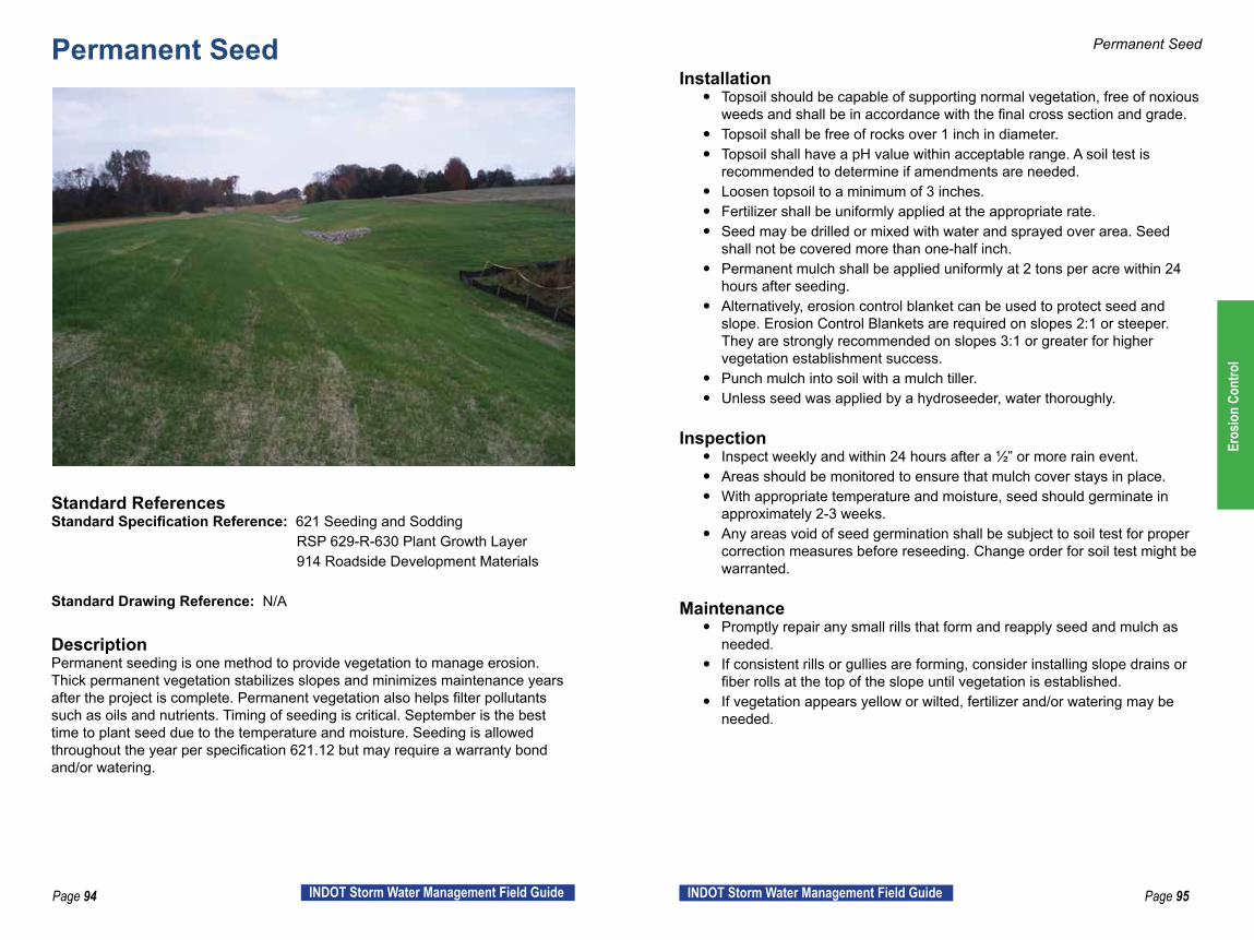
DescriptionPermanent seeding is one method to provide vegetation to manage erosion. Thick permanent vegetation stabilizes slopes and minimizes maintenance years after the project is complete. Permanent vegetation also helps filter pollutants such as oils and nutrients. Timing of seeding is critical. September is the best time to plant seed due to the temperature and moisture. Seeding is allowed throughout the year per specification 621.12 but may require a warranty bond and/or watering.
Permanent Seed
Installation y Topsoil should be capable of supporting normal vegetation, free of noxious
weeds and shall be in accordance with the final cross section and grade. y Topsoil shall be free of rocks over 1 inch in diameter. y Topsoil shall have a pH value within acceptable range. A soil test is
recommended to determine if amendments are needed. y Loosen topsoil to a minimum of 3 inches. y Fertilizer shall be uniformly applied at the appropriate rate. y Seed may be drilled or mixed with water and sprayed over area. Seed
shall not be covered more than one-half inch. y Permanent mulch shall be applied uniformly at 2 tons per acre within 24
hours after seeding. y Alternatively, erosion control blanket can be used to protect seed and
slope. Erosion Control Blankets are required on slopes 2:1 or steeper. They are strongly recommended on slopes 3:1 or greater for higher vegetation establishment success.
y Punch mulch into soil with a mulch tiller. y Unless seed was applied by a hydroseeder, water thoroughly.
Inspection y Inspect weekly and within 24 hours after a ½” or more rain event. y Areas should be monitored to ensure that mulch cover stays in place. y With appropriate temperature and moisture, seed should germinate in
approximately 2-3 weeks. y Any areas void of seed germination shall be subject to soil test for proper
correction measures before reseeding. Change order for soil test might be warranted.
Maintenance y Promptly repair any small rills that form and reapply seed and mulch as
needed. y If consistent rills or gullies are forming, consider installing slope drains or
fiber rolls at the top of the slope until vegetation is established. y If vegetation appears yellow or wilted, fertilizer and/or watering may be
needed.
Eros
ion
Cont
rol
Page 96 INDOT Storm Water Management Field Guide Page 97INDOT Storm Water Management Field Guide
Permanent Seed Permanent Seed
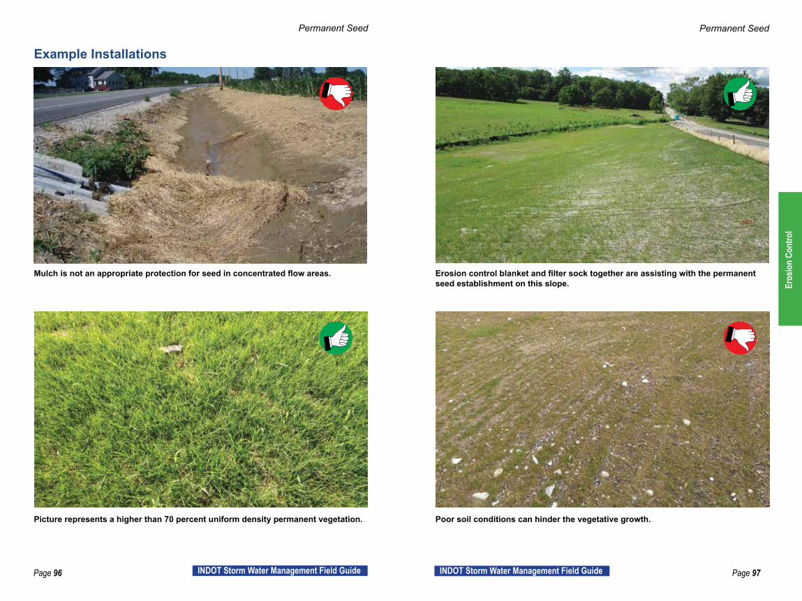
Mulch is not an appropriate protection for seed in concentrated flow areas. Erosion control blanket and filter sock together are assisting with the permanent seed establishment on this slope.
Picture represents a higher than 70 percent uniform density permanent vegetation. Poor soil conditions can hinder the vegetative growth.
Example Installations
Eros
ion
Cont
rol
Page 98 INDOT Storm Water Management Field Guide Page 99INDOT Storm Water Management Field Guide
Permanent Sod
Standard ReferencesStandard Specification Reference: 621 Seeding and Sodding RSP 629-R-630 Plant Growth Layer 914 Roadside Development Materials
Standard Drawing Reference: Sod typical drawing within plan details
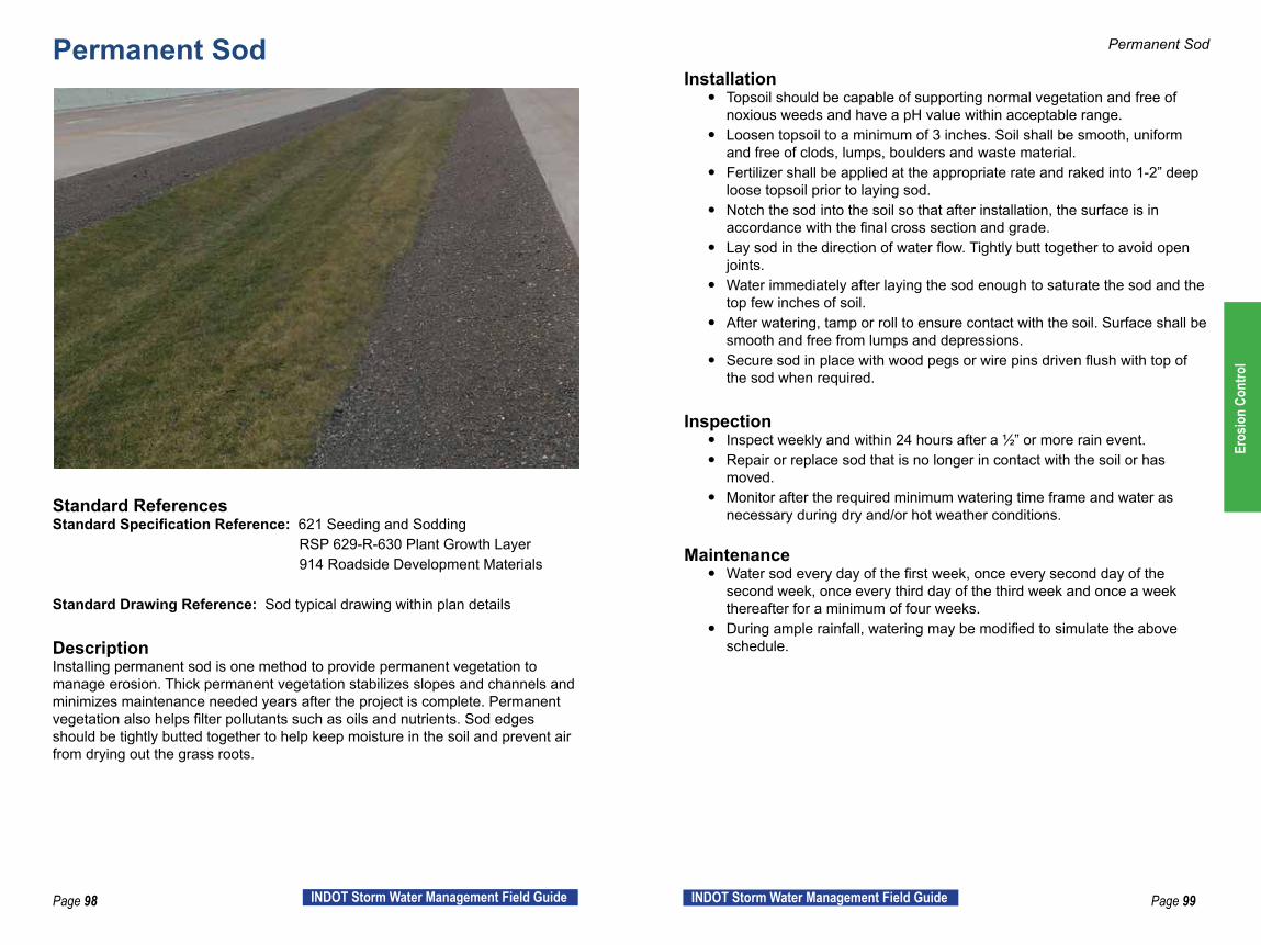
DescriptionInstalling permanent sod is one method to provide permanent vegetation to manage erosion. Thick permanent vegetation stabilizes slopes and channels and minimizes maintenance needed years after the project is complete. Permanent vegetation also helps filter pollutants such as oils and nutrients. Sod edges should be tightly butted together to help keep moisture in the soil and prevent air from drying out the grass roots.
Permanent Sod
Installation y Topsoil should be capable of supporting normal vegetation and free of
noxious weeds and have a pH value within acceptable range. y Loosen topsoil to a minimum of 3 inches. Soil shall be smooth, uniform
and free of clods, lumps, boulders and waste material. y Fertilizer shall be applied at the appropriate rate and raked into 1-2” deep
loose topsoil prior to laying sod. y Notch the sod into the soil so that after installation, the surface is in
accordance with the final cross section and grade. y Lay sod in the direction of water flow. Tightly butt together to avoid open
joints. y Water immediately after laying the sod enough to saturate the sod and the
top few inches of soil. y After watering, tamp or roll to ensure contact with the soil. Surface shall be
smooth and free from lumps and depressions. y Secure sod in place with wood pegs or wire pins driven flush with top of
the sod when required.
Inspection y Inspect weekly and within 24 hours after a ½” or more rain event. y Repair or replace sod that is no longer in contact with the soil or has
moved. y Monitor after the required minimum watering time frame and water as
necessary during dry and/or hot weather conditions.
Maintenance y Water sod every day of the first week, once every second day of the
second week, once every third day of the third week and once a week thereafter for a minimum of four weeks.
y During ample rainfall, watering may be modified to simulate the above schedule.
Eros
ion
Cont
rol

Page 100 INDOT Storm Water Management Field Guide Page 101INDOT Storm Water Management Field Guide
Permanent Sod Permanent Sod
Area upstream of sodded ditch is not stable and causing sedimentation on permanent sod.
Sod failed because it was installed on a thick bed of straw mulch. An adequate growing surface is needed for the sod to take root.
When placing sod in a ditch, extend the sod up the slope to prevent scour on the edge of the sod. Notch sod into the soil so that there is a smooth surface transition in accordance with the final cross section and grade.
Permanent sod installed in concentrated flow area in median. Sod was not adequately watered or otherwise maintained.
Example Installations
Eros
ion
Cont
rol

Page 102 INDOT Storm Water Management Field Guide Page 103INDOT Storm Water Management Field Guide
Sediment ControlIf previous storm water management efforts have been exhausted, sediment control BMPs will be needed to minimize sediment and other pollution from leaving the site. Sediment control measures are designed to slow water down long enough for sediment particles to settle out of flowing water. Smaller particles (such as clay) need more time to settle out than larger particles (such as sand). Because of this, sediment control features are not very effective in areas with clay soils. This is why the focus should be on other management tools (Communication, Work Management, Storm Water Management and Erosion Control). Once soil is on the move, it’s hard and expensive to manage. Generally, sediment control measures are the most expensive, require the most maintenance, and are the least effective storm water management tools.
Successful Strategies to Save Time and Money
Last Line of Defense y Use all other Best Management Practices (Communication, Work
Management, Storm Water Management and Erosion Control) so that sediment control measures do not need as much maintenance.
y Sediment control measures are like the safety position in football. An effective team uses all defensive players with the safety as the last line of defense.
Plan for Maintenance y When sediment control measures are placed, install them in a location
where they can easily be maintained. If the last measure cannot easily be maintained, consider additional measures that minimize maintenance needs.
Consider the Watershed y Sediment control measures should be designed to handle the sediment
load and storm water velocity of the entire watershed. y If the watershed size is not known, existing features such as ditch size,
pipe size, etc. will provide an indication of an appropriate sediment trap or basin size.
Sedi
men
t Con
trol
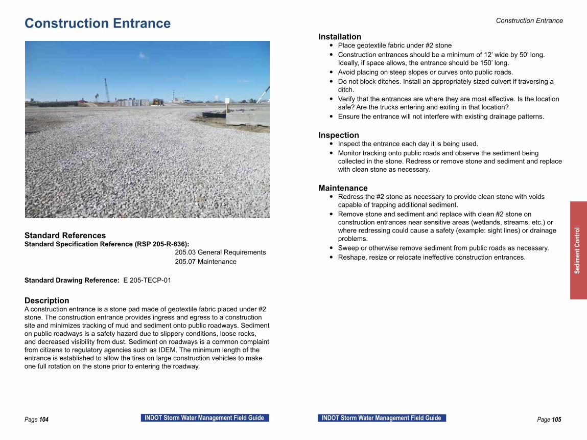
Page 104 INDOT Storm Water Management Field Guide Page 105INDOT Storm Water Management Field Guide
Construction Entrance
Standard ReferencesStandard Specification Reference (RSP 205-R-636): 205.03 General Requirements 205.07 Maintenance
Standard Drawing Reference: E 205-TECP-01
DescriptionA construction entrance is a stone pad made of geotextile fabric placed under #2 stone. The construction entrance provides ingress and egress to a construction site and minimizes tracking of mud and sediment onto public roadways. Sediment on public roadways is a safety hazard due to slippery conditions, loose rocks, and decreased visibility from dust. Sediment on roadways is a common complaint from citizens to regulatory agencies such as IDEM. The minimum length of the entrance is established to allow the tires on large construction vehicles to make one full rotation on the stone prior to entering the roadway.
Construction Entrance
Installation y Place geotextile fabric under #2 stone y Construction entrances should be a minimum of 12’ wide by 50’ long.
Ideally, if space allows, the entrance should be 150’ long. y Avoid placing on steep slopes or curves onto public roads. y Do not block ditches. Install an appropriately sized culvert if traversing a
ditch. y Verify that the entrances are where they are most effective. Is the location
safe? Are the trucks entering and exiting in that location? y Ensure the entrance will not interfere with existing drainage patterns.
Inspection y Inspect the entrance each day it is being used. y Monitor tracking onto public roads and observe the sediment being
collected in the stone. Redress or remove stone and sediment and replace with clean stone as necessary.
Maintenance y Redress the #2 stone as necessary to provide clean stone with voids
capable of trapping additional sediment. y Remove stone and sediment and replace with clean #2 stone on
construction entrances near sensitive areas (wetlands, streams, etc.) or where redressing could cause a safety (example: sight lines) or drainage problems.
y Sweep or otherwise remove sediment from public roads as necessary. y Reshape, resize or relocate ineffective construction entrances.
Sedi
men
t Con
trol
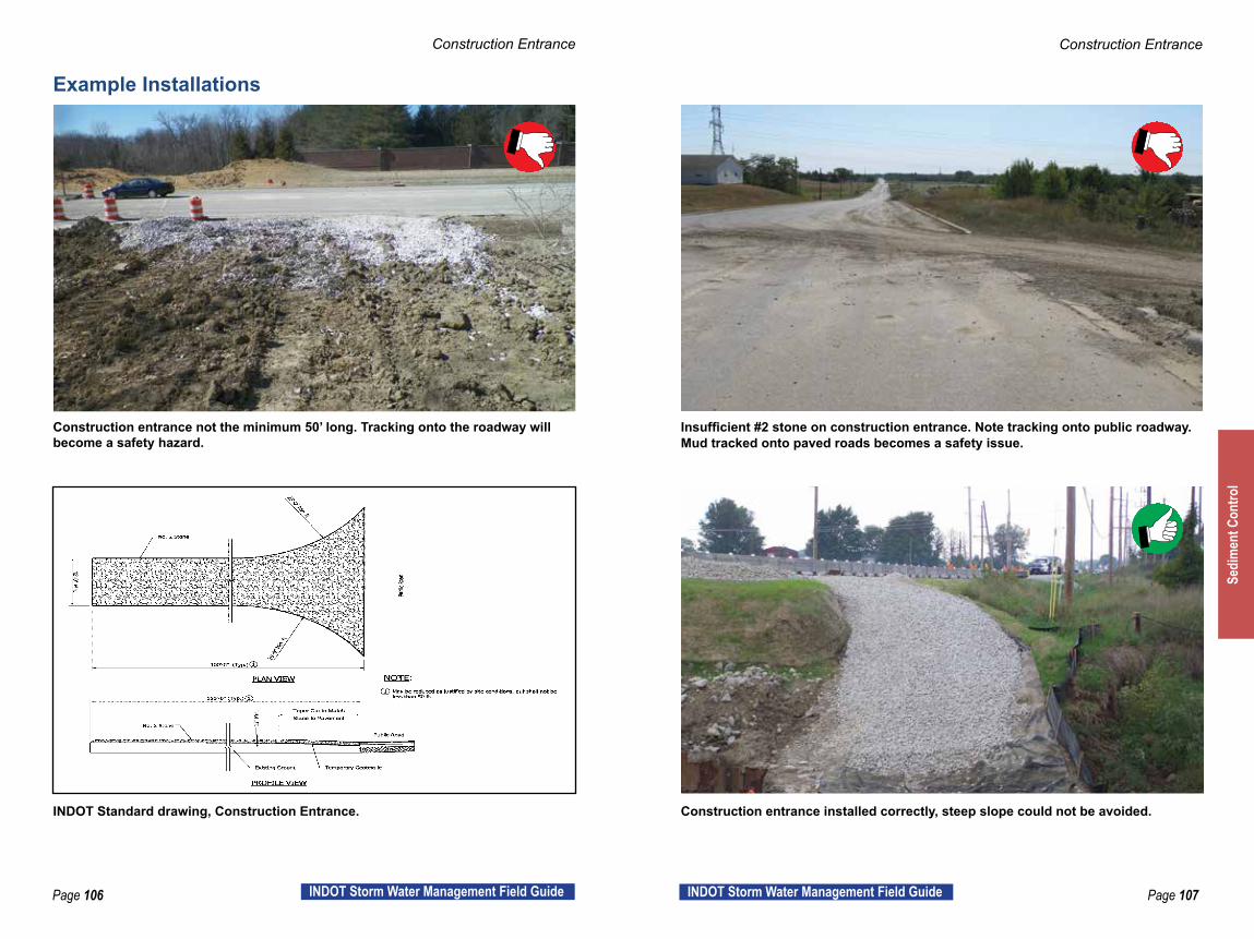
Page 106 INDOT Storm Water Management Field Guide Page 107INDOT Storm Water Management Field Guide
Construction Entrance Construction Entrance
Construction entrance not the minimum 50’ long. Tracking onto the roadway willbecome a safety hazard.
Insufficient #2 stone on construction entrance. Note tracking onto public roadway. Mud tracked onto paved roads becomes a safety issue.
INDOT Standard drawing, Construction Entrance. Construction entrance installed correctly, steep slope could not be avoided.
Example Installations
Sedi
men
t Con
trol

Page 108 INDOT Storm Water Management Field Guide Page 109INDOT Storm Water Management Field Guide
Silt Fence
Standard ReferencesStandard Specification Reference (RSP 205-R-636): 205.06 (a) Silt Fence 205.07 (a) Maintenance
Standard Drawing Reference: E 205-TECP-02
DescriptionSilt fences are used primarily as perimeter protection in sheet flow areas. Install silt fence to trap sediment from small, disturbed areas by reducing the velocity of sheet flow. Silt fence captures sediment by ponding water to allow deposition, not by filtration. Silt fence should not be used as a diversion and should not be installed across a stream, channel, ditch, swale, or anywhere that concentrated flow is anticipated.
Silt Fence
Installation y The contractor’s SWQM and the INDOT PE/PS should discuss silt fence
locations prior to installation. y Install prior to earthwork or clearing operations. y Do not place silt fence in concentrated flow areas. y Do not install silt fence perpendicular to slopes. y Do not install silt fence in floodways. y Trench in the bottom of silt fence and install joints per the INDOT standard
drawing. y Place silt fence along a contour and “J” hook the ends to tie into the slope. y Allow access for maintenance if possible. If maintenance access is
impossible or difficult, plan additional erosion control measures to reduce the need for silt fence maintenance.
Inspection y Inspect weekly and within 24 hours after a ½” or more rain event. y Check for torn, decomposed or ineffective fence. y Ensure fence is trenched in and placed along a contour. y Check for sediment accumulations and areas where fence has fallen. y Check for “J” hooks at the end of silt fence runs.
Maintenance y Repair or replace silt fence if torn, starting to decompose, damaged by
construction equipment, or is ineffective. Correct any “J” hook problems at the end of runs.
y Remove sediment once it reaches one-half the height of the fence. Se
dim
ent C
ontro
l
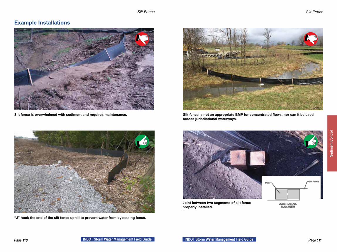
Page 110 INDOT Storm Water Management Field Guide Page 111INDOT Storm Water Management Field Guide
Silt Fence Silt Fence
Silt fence is overwhelmed with sediment and requires maintenance. Silt fence is not an appropriate BMP for concentrated flows, nor can it be used across jurisdictional waterways.
“J” hook the end of the silt fence uphill to prevent water from bypassing fence.
Joint between two segments of silt fence properly installed.
Example Installations
Sedi
men
t Con
trol
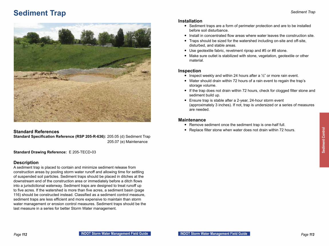
Page 112 INDOT Storm Water Management Field Guide Page 113INDOT Storm Water Management Field Guide
Sediment Trap
Standard ReferencesStandard Specification Reference (RSP 205-R-636): 205.05 (d) Sediment Trap 205.07 (e) Maintenance
Standard Drawing Reference: E 205-TECD-03
DescriptionA sediment trap is placed to contain and minimize sediment release from construction areas by pooling storm water runoff and allowing time for settling of suspended soil particles. Sediment traps should be placed in ditches at the downstream end of the construction area or immediately before a ditch flows into a jurisdictional waterway. Sediment traps are designed to treat runoff up to five acres. If the watershed is more than five acres, a sediment basin (page 116) should be constructed instead. Classified as a sediment control measure, sediment traps are less efficient and more expensive to maintain than storm water management or erosion control measures. Sediment traps should be the last measure in a series for better Storm Water management.
Sediment Trap
Installation y Sediment traps are a form of perimeter protection and are to be installed
before soil disturbance. y Install in concentrated flow areas where water leaves the construction site. y Traps should be sized for the watershed including on-site and off-site,
disturbed, and stable areas. y Use geotextile fabric, revetment riprap and #5 or #8 stone. y Make sure outlet is stabilized with stone, vegetation, geotextile or other
material.
Inspection y Inspect weekly and within 24 hours after a ½” or more rain event. y Water should drain within 72 hours of a rain event to regain the trap’s
storage volume. y If the trap does not drain within 72 hours, check for clogged filter stone and
sediment build up. y Ensure trap is stable after a 2-year, 24-hour storm event
(approximately 3 inches). If not, trap is undersized or a series of measures are needed.
Maintenance y Remove sediment once the sediment trap is one-half full. y Replace filter stone when water does not drain within 72 hours.
Sedi
men
t Con
trol
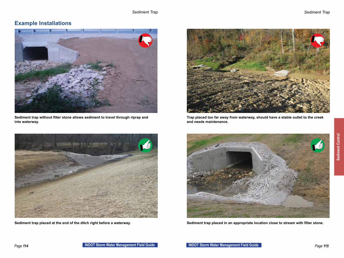
Page 114 INDOT Storm Water Management Field Guide Page 115INDOT Storm Water Management Field Guide
Sediment Trap Sediment Trap
Sediment trap without filter stone allows sediment to travel through riprap and into waterway.
Trap placed too far away from waterway, should have a stable outlet to the creek and needs maintenance.
Sediment trap placed at the end of the ditch right before a waterway. Sediment trap placed in an appropriate location close to stream with filter stone.
Example Installations
Sedi
men
t Con
trol

Page 116 INDOT Storm Water Management Field Guide Page 117INDOT Storm Water Management Field Guide
Sediment Basin
Standard ReferencesStandard Specification Reference RSP 205-R-636: 205.05 (e) Sediment Basin 205.07 (b) Maintenance
Standard Drawing Reference: N/A. Contract specific design
DescriptionSediment basins consist of an embankment constructed basin with a riprap and filter stone encased perforated stand pipe near the downslope side. The stand pipe outflows through a connected buried pipe within the downslope embankment wall. Sediment basins are placed in order to minimize sediment release from construction areas by pooling storm water runoff and allowing time for the suspended soil particles to settle out of the storm water. They are contract specific and designed to accommodate storm water runoff and sediment from large areas. Sediment basins are designed to treat runoff from approximately 5 to 30 acres and should be placed as close to the sediment source as possible.
Sediment Basin
Installation y The INDOT PE/PS and the Contractor’s SWQM should discuss the
locations and sizes of the designed sediment basins prior to installation. y Install sediment basins in concentrated flow areas where water leaves the
construction site. y Basins should be sized for watersheds that include on-site and off-site
areas and should also account for both disturbed and stable areas. They should accommodate no more than 30 acres of watershed.
y Ensure the basin has stable slopes, stable outlet overflow, perforated stand pipe placed to the correct height (2’ below the top of basin), and #5 or #8 filter stone surrounding the riprap core.
y Make sure the outlet is stabilized with stone, vegetation, geotextile or other suitable material.
Inspection y Inspect weekly and within 24 hours after a ½” or more rain event. y Check to ensure that the basin drains within 72 hours of a rain event. y Check for clogged filter stone and sediment build up.
Maintenance y Remove sediment once design volume (check plans) is reached. y Replace filter stone when water does not drain within 72 hours.
Sedi
men
t Con
trol

Page 118 INDOT Storm Water Management Field Guide Page 119INDOT Storm Water Management Field Guide
Sediment Basin Sediment Basin
Sediment basin slopes are not stable and no filter stone is used on perforated stand pipe.
Sediment basins must have stable banks and a stable outlet, this live outfall structure is buried in sediment along with the straw bales being used to protect the structure.
Sediment basin stabilized with vegetated banks, riser pipe and stable overflow. Sediment basin with stable slopes, stable outlets, filter stone and stand pipe.
Example Installations
Sedi
men
t Con
trol

Page 120 INDOT Storm Water Management Field Guide Page 121INDOT Storm Water Management Field Guide
Filter Berm
Standard ReferencesStandard Specification Reference (RSP 205-R-636): 205.06 (b) Filter Berm 205.07 (c) MaintenanceStandard Drawing Reference: N/A
DescriptionFilter berms are used to trap sediment from long, linear disturbed areas by reducing the velocity and dissipating the energy of sheet flow. Filter berms capture sediment by filtering storm water runoff and by ponding smaller amounts of water at their base to allow settling and deposition. A filter berm can be constructed with rock, compost, or filter socks. Only rock filter berms can be used where more concentrated flows are anticipated.
Filter Berm
Installation y Discuss the locations, materials and timing of the construction of filter
berms with the Contractor’s SWQM. y Install filter berms along the perimeter of the construction area close to
locations where runoff would enter an adjacent waterway in primarily sheet flow areas. Only rock filter berms can be installed for concentrated flow areas.
y Rock filter berms should include geotextile fabric with riprap placed on top. #5 or #8 filter stone should be added to the upslope side of the riprap berm.
y Wood chips from tree clearing operations or filter socks can be used as filter berms, but only where water velocity is low.
Inspection y Inspect weekly and within 24 hours after a ½” or more rain event. y Monitor for sediment accumulation. y Look for areas that have been damaged by storm water or equipment.
Maintenance y Remove sediment once it reaches one-quarter the height of the berm. y Repair damaged areas as needed or directed.
Sedi
men
t Con
trol

Page 122 INDOT Storm Water Management Field Guide Page 123INDOT Storm Water Management Field Guide
Filter Berm Filter Berm
Filter berm after a large rain event that needs maintenance. Filter berm protecting creek from long fill slope. Note existing vegetation left in place along creek bank.
Filter berm protecting creek with geotextile, revetment riprap and filter stone. Note existing vegetation left in place between filter berm and waterway.
A rock filter berm would have been the correct BMP for this situation. Silt fence not sufficient and not functioning properly, sediment has moved into the stream from the unprotected slope and bank.
Example Installations
Sedi
men
t Con
trol
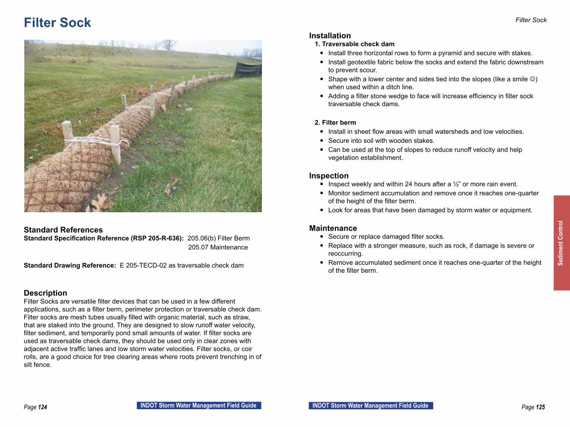
Page 124 INDOT Storm Water Management Field Guide Page 125INDOT Storm Water Management Field Guide
Filter Sock
Standard ReferencesStandard Specification Reference (RSP 205-R-636): 205.06(b) Filter Berm 205.07 Maintenance
Standard Drawing Reference: E 205-TECD-02 as traversable check dam
DescriptionFilter Socks are versatile filter devices that can be used in a few different applications, such as a filter berm, perimeter protection or traversable check dam. Filter socks are mesh tubes usually filled with organic material, such as straw, that are staked into the ground. They are designed to slow runoff water velocity, filter sediment, and temporarily pond small amounts of water. If filter socks are used as traversable check dams, they should be used only in clear zones with adjacent active traffic lanes and low storm water velocities. Filter socks, or coir rolls, are a good choice for tree clearing areas where roots prevent trenching in of silt fence.
Filter Sock
Installation 1. Traversable check dam
y Install three horizontal rows to form a pyramid and secure with stakes. y Install geotextile fabric below the socks and extend the fabric downstream
to prevent scour. y Shape with a lower center and sides tied into the slopes (like a smile )
when used within a ditch line. y Adding a filter stone wedge to face will increase efficiency in filter sock
traversable check dams.
2. Filter berm y Install in sheet flow areas with small watersheds and low velocities. y Secure into soil with wooden stakes. y Can be used at the top of slopes to reduce runoff velocity and help
vegetation establishment.
Inspection y Inspect weekly and within 24 hours after a ½” or more rain event. y Monitor sediment accumulation and remove once it reaches one-quarter
of the height of the filter berm. y Look for areas that have been damaged by storm water or equipment.
Maintenance y Secure or replace damaged filter socks. y Replace with a stronger measure, such as rock, if damage is severe or
reoccurring. y Remove accumulated sediment once it reaches one-quarter of the height
of the filter berm.
Sedi
men
t Con
trol
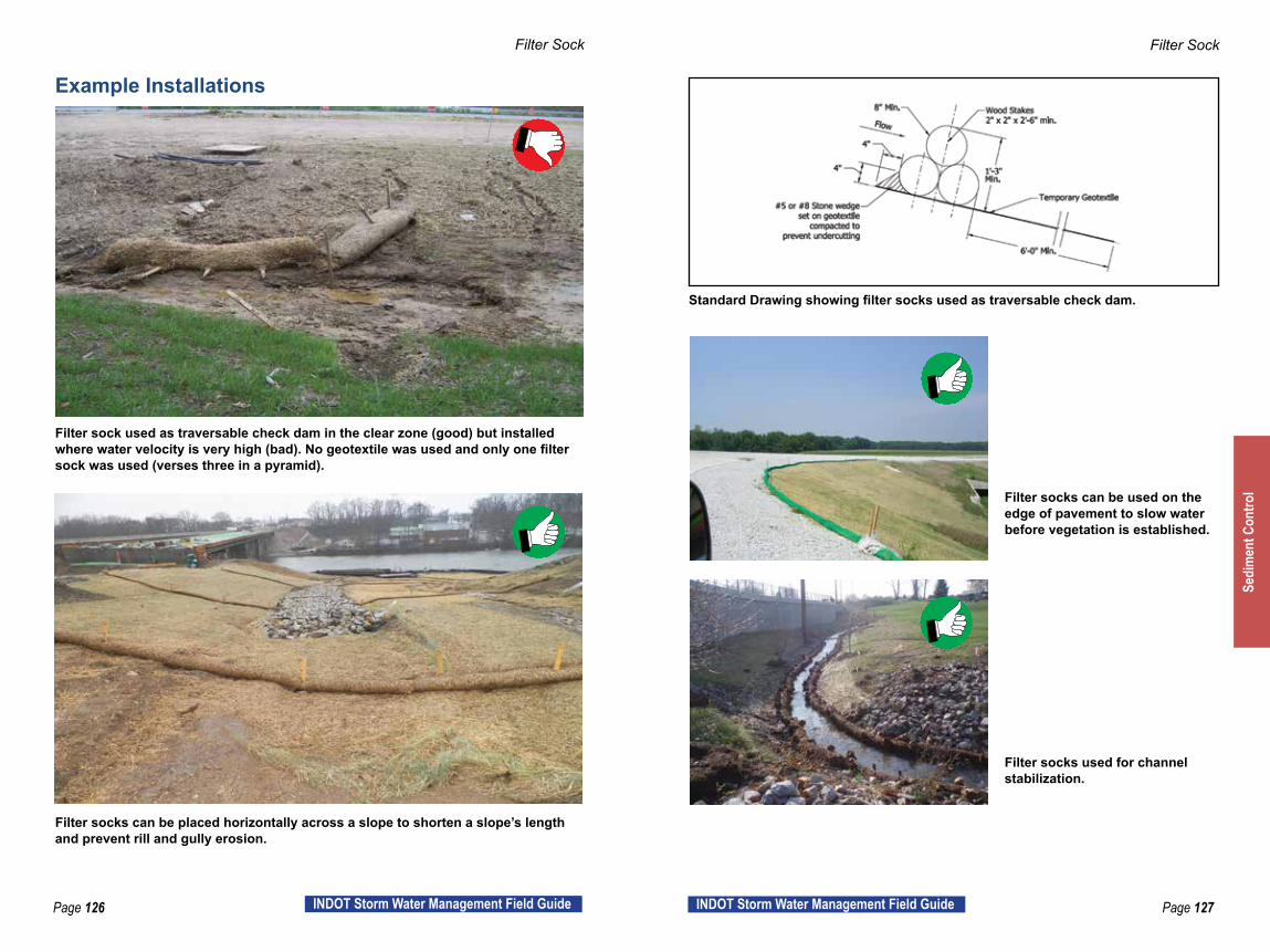
Page 126 INDOT Storm Water Management Field Guide Page 127INDOT Storm Water Management Field Guide
Filter Sock Filter Sock
Filter sock used as traversable check dam in the clear zone (good) but installed where water velocity is very high (bad). No geotextile was used and only one filter sock was used (verses three in a pyramid).
Filter socks can be used on the edge of pavement to slow water before vegetation is established.
Standard Drawing showing filter socks used as traversable check dam.
Filter socks can be placed horizontally across a slope to shorten a slope’s length and prevent rill and gully erosion.
Filter socks used for channel stabilization.
Example Installations
Sedi
men
t Con
trol

Page 128 INDOT Storm Water Management Field Guide Page 129INDOT Storm Water Management Field Guide
Inlet Protection
Standard ReferencesStandard Specification Reference (RSP 205-R-636): 205.05 (i) Inlet Protection 205.07 (d) Maintenance
Standard Drawing Reference: E 205-TECI-01 through E 205-TECI-06
DescriptionInlets are designed to carry moderate and large flows of storm water. Inlets also have the potential to transport sediment to streams, rivers, wetlands and lakes if they are not properly protected. This sediment control measure can be the last chance to remove sediment before storm water leaves the job site. Inlet protection can take many forms and a review of the Standard Drawings listed above will better illustrate these methods. The choices within the Standard Drawings or plan details will allow for a “best fit” solution to specific construction situations. Inlet protection may need to be coordinated with a local MS4.
Inlet Protection
Installation y Discuss the inlet protection methods with all personnel involved in the
installation. Choose the best method for project conditions, urban street conditions are different from rural road conditions.
y Install the specified inlet protection so that storm water does not bypass the inlet.
y Install top cross bracing and trench in silt fence when using geotextile box. y Use #8 filter stone and #2 coarse aggregate for gravel ring. y Follow the standard drawing and/or manufacturers installation information
(when using a commercially available product) when installing inlet bag type protection for inlets.
y Do not place this type of protection within any jurisdictional waterways.
Inspection y Inspect weekly and after every rain event. y Look for inlet protection materials that are damaged, clogged or have
become ineffective. y Make sure storm water is not bypassing or undercutting any type of inlet
protection that has been installed.
Maintenance y Remove sediment after each storm event. y If measure is repeatedly damaged or clogged, consider additional erosion
and sediment control measures upstream in a series. y Cleaning by flushing with water will not be allowed y Remember, only rain goes down the drain.
Sedi
men
t Con
trol
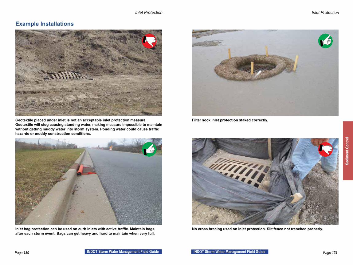
Page 130 INDOT Storm Water Management Field Guide Page 131INDOT Storm Water Management Field Guide
Inlet Protection Inlet Protection
Geotextile placed under inlet is not an acceptable inlet protection measure. Geotextile will clog causing standing water, making measure impossible to maintain without getting muddy water into storm system. Ponding water could cause traffic hazards or muddy construction conditions.
Filter sock inlet protection staked correctly.
Inlet bag protection can be used on curb inlets with active traffic. Maintain bags after each storm event. Bags can get heavy and hard to maintain when very full.
No cross bracing used on inlet protection. Silt fence not trenched properly.
Example Installations
Sedi
men
t Con
trol
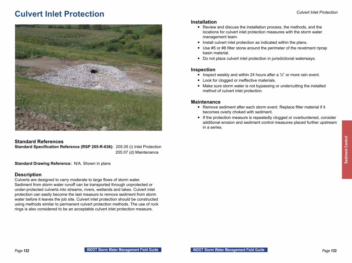
Page 132 INDOT Storm Water Management Field Guide Page 133INDOT Storm Water Management Field Guide
Culvert Inlet Protection
Standard ReferencesStandard Specification Reference (RSP 205-R-636): 205.05 (i) Inlet Protection 205.07 (d) Maintenance
Standard Drawing Reference: N/A. Shown in plans
DescriptionCulverts are designed to carry moderate to large flows of storm water. Sediment from storm water runoff can be transported through unprotected or under-protected culverts into streams, rivers, wetlands and lakes. Culvert inlet protection can easily become the last measure to remove sediment from storm water before it leaves the job site. Culvert inlet protection should be constructed using methods similar to permanent culvert protection methods. The use of rock rings is also considered to be an acceptable culvert inlet protection measure.
Culvert Inlet Protection
Installation y Review and discuss the installation process, the methods, and the
locations for culvert inlet protection measures with the storm water management team.
y Install culvert inlet protection as indicated within the plans. y Use #5 or #8 filter stone around the perimeter of the revetment riprap
basin material. y Do not place culvert inlet protection in jurisdictional waterways.
Inspection y Inspect weekly and within 24 hours after a ½” or more rain event. y Look for clogged or ineffective materials. y Make sure storm water is not bypassing or undercutting the installed
method of culvert inlet protection.
Maintenance y Remove sediment after each storm event. Replace filter material if it
becomes overly choked with sediment. y If the protection measure is repeatedly clogged or overburdened, consider
additional erosion and sediment control measures placed further upstream in a series.
Sedi
men
t Con
trol

Page 134 INDOT Storm Water Management Field Guide Page 135INDOT Storm Water Management Field Guide
Culvert Inlet Protection Culvert Inlet Protection
Silt fence should not be located in concentrated flow areas and is not appropriate as culvert inlet protection.
Although not an INDOT standard, straw bales and riprap functioning well for culvert inlet protection.
Inlet protected from sediment with filter stone surrounding riprap. Culvert inlet protection not shaped correctly contributing to scour around inlet.
Example Installations
Sedi
men
t Con
trol
Page 136 INDOT Storm Water Management Field Guide Page 137INDOT Storm Water Management Field Guide
Other Pollution Prevention Exposed soil and sediment are not the only pollutants exposed to storm water on construction sites. Other pollution prevention methods should be utilized to protect the environment when constructing and maintaining roads and bridges. Careful handling and storage of construction materials will help ensure our natural resources are protected.
Successful Strategies to Save Time and Money
Protect Natural Resources y Locate stockpiles, temporary toilets, concrete waste water containment,
fueling operations, etc. as far away from sensitive areas such as streams and wetlands as possible.
y Remove cofferdams, temporary crossings and other features within streams as carefully as possible. Do not over excavate or churn up muddy water unnecessarily.
Treat Chemicals with Care y Ensure the concrete washout is adequately sized and completely
contained. Chemicals in concrete washout raise pH levels and can result in high alkaline runoff which cause fish kills in streams, soil contamination and severe human health risks.
y Store chemicals such as fertilizers, petroleum products and sealants inside if possible. Always protect chemicals in sealed containers so there is no exposure to storm water.
y Use secondary containment for all fuel storage.
Maintain Equipment y Ensure all equipment is maintained in good working order. Fix fuel, oil or
other fluid leaks as soon as they are discovered. y Remove contaminated soils or otherwise clean up the job site due to these
leaks immediately.
Othe
r Pol
lutio
n Pr
even
tion

Page 138 INDOT Storm Water Management Field Guide Page 139INDOT Storm Water Management Field Guide
Temporary Crossing
Standard ReferencesStandard Specification Reference: 107.02 Permits, Licenses and Taxes RSP 205-R-636: 205.07 Maintenance
Standard Drawing Reference: N/A. Designed for specific site conditions.
DescriptionA temporary crossing is intended to be installed in a stream or waterway for short-term use by construction vehicles or heavy equipment. Temporary stream crossings are individually designed and are specific to the stream and conditions encountered at the site. If the crossing has not been included as part of the plans, the contractor is responsible to develop and submit for approval the design for the crossing. The contractor is responsible for obtaining permits for temporary impacts such as crossings, cofferdams and demolition of structures if these issues are not covered under the IDEM 401, USACE 404, and IDNR Construction in a Floodway permits.
Temporary Crossing
Installation y Have discussions with all storm water team members involved in the
installation to determine and clarify the construction methods and procedures, and to ensure proper permitting of the crossing prior to construction.
y Crossings should be placed to disturb as little of the existing stream bed and banks as possible and sized to carry a minimum of a two-year, 24-hour storm event. Construct the overflow for 10-year, 24-hour storm.
y Temporary crossings should be constructed with riprap large enough to not allow the stone to wash down stream.
y Re-grade, re-seed or otherwise stabilize areas of removed vegetation.
Inspection y Inspect weekly and within 24 hours after a ½” or more rain event. y Check for accumulation of debris and obstructions such as limbs, trash,
rocks, etc. at culvert openings; remove promptly as needed. y Inspect for erosion of stream banks and approach road and repair
promptly as needed. y Inspect for sediment accumulation in the stone and replace as needed.
Maintenance y Remove debris or other obstructions and repair eroded areas promptly. y Periodically remove built up sediment carefully to ensure 10-year, 24-hour
overflow is maintained. Replace the sediment laden stone as needed. y When no longer needed, remove the crossing with as little creek
disturbance as possible.
Othe
r Pol
lutio
n Pr
even
tion

Page 140 INDOT Storm Water Management Field Guide Page 141INDOT Storm Water Management Field Guide
Temporary Crossing Temporary Crossing
Pipes under temporary crossing are undersized causing creek to widen upstream. #2 stone on temporary crossing needs to be redressed to reduce sediment entering creek during rain events.
Temporary crossing with adequate pipe capacity. These temporary impacts must be permitted, usually by the contractor, prior to installation and should be removed as soon as practical.
The use of this temporary bridge along with rock and geotextile fabric helps protect this stream from repeated equipment crossing.
Example Installations
Othe
r Pol
lutio
n Pr
even
tion
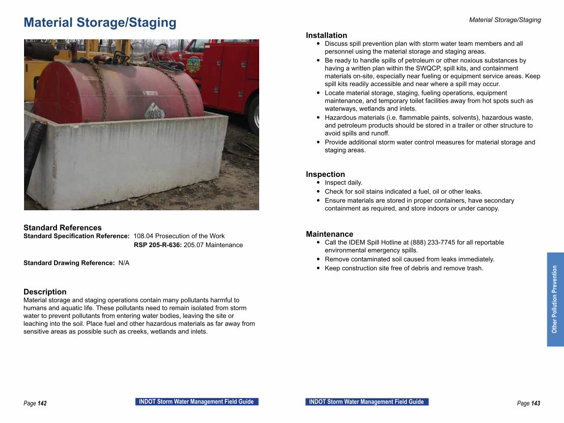
Page 142 INDOT Storm Water Management Field Guide Page 143INDOT Storm Water Management Field Guide
Material Storage/Staging
Standard ReferencesStandard Specification Reference: 108.04 Prosecution of the Work RSP 205-R-636: 205.07 Maintenance
Standard Drawing Reference: N/A
DescriptionMaterial storage and staging operations contain many pollutants harmful to humans and aquatic life. These pollutants need to remain isolated from storm water to prevent pollutants from entering water bodies, leaving the site or leaching into the soil. Place fuel and other hazardous materials as far away from sensitive areas as possible such as creeks, wetlands and inlets.
Material Storage/Staging
Installation y Discuss spill prevention plan with storm water team members and all
personnel using the material storage and staging areas. y Be ready to handle spills of petroleum or other noxious substances by
having a written plan within the SWQCP, spill kits, and containment materials on-site, especially near fueling or equipment service areas. Keep spill kits readily accessible and near where a spill may occur.
y Locate material storage, staging, fueling operations, equipment maintenance, and temporary toilet facilities away from hot spots such as waterways, wetlands and inlets.
y Hazardous materials (i.e. flammable paints, solvents), hazardous waste, and petroleum products should be stored in a trailer or other structure to avoid spills and runoff.
y Provide additional storm water control measures for material storage and staging areas.
Inspection y Inspect daily. y Check for soil stains indicated a fuel, oil or other leaks. y Ensure materials are stored in proper containers, have secondary
containment as required, and store indoors or under canopy.
Maintenance y Call the IDEM Spill Hotline at (888) 233-7745 for all reportable
environmental emergency spills. y Remove contaminated soil caused from leaks immediately. y Keep construction site free of debris and remove trash.
Othe
r Pol
lutio
n Pr
even
tion
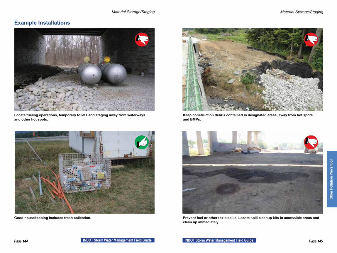
Page 144 INDOT Storm Water Management Field Guide Page 145INDOT Storm Water Management Field Guide
Material Storage/Staging Material Storage/Staging
Locate fueling operations, temporary toilets and staging away from waterways and other hot spots.
Keep construction debris contained in designated areas, away from hot spots and BMPs.
Good housekeeping includes trash collection. Prevent fuel or other toxic spills. Locate spill cleanup kits in accessible areas and clean up immediately.
Example Installations
Othe
r Pol
lutio
n Pr
even
tion
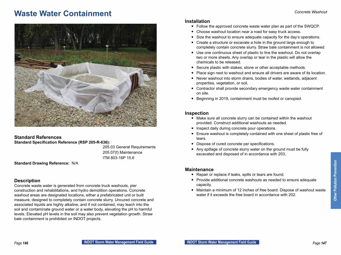
Page 146 INDOT Storm Water Management Field Guide Page 147INDOT Storm Water Management Field Guide
Waste Water Containment
Standard ReferencesStandard Specification Reference (RSP 205-R-636): 205.03 General Requirements 205.07(f) Maintenance ITM 803-16P 15.6Standard Drawing Reference: N/A
DescriptionConcrete waste water is generated from concrete truck washouts, pier construction and rehabilitations, and hydro demolition operations. Concrete washout areas are designated locations, either a prefabricated unit or built measure, designed to completely contain concrete slurry. Uncured concrete and associated liquids are highly alkaline, and if not contained, may leach into the soil and contaminate ground water or a water body, elevating the pH to harmful levels. Elevated pH levels in the soil may also prevent vegetation growth. Straw bale containment is prohibited on INDOT projects.
Concrete Washout
Installation y Follow the approved concrete waste water plan as part of the SWQCP. y Choose washout location near a road for easy truck access. y Size the washout to ensure adequate capacity for the day’s operations. y Create a structure or excavate a hole in the ground large enough to
completely contain concrete slurry. Straw bale containment is not allowed. y Use one continuous sheet of plastic to line the washout. Do not overlap
two or more sheets. Any overlap or tear in the plastic will allow the chemicals to be released.
y Secure plastic with stakes, stone or other acceptable methods. y Place sign next to washout and ensure all drivers are aware of its location. y Never washout into storm drains, bodies of water, wetlands, adjacent
properties, vegetation, or soil. y Contractor shall provide secondary emergency waste water containment
on site. y Beginning in 2019, containment must be roofed or canopied.
Inspection y Make sure all concrete slurry can be contained within the washout
provided. Construct additional washouts as needed. y Inspect daily during concrete pour operations. y Ensure washout is completely contained with one sheet of plastic free of
tears. y Dispose of cured concrete per specifications. y Any spillage of concrete slurry water on the ground must be fully
excavated and disposed of in accordance with 203.
Maintenance y Repair or replace if leaks, spills or tears are found. y Provide additional concrete washouts as needed to ensure adequate
capacity. y Maintain a minimum of 12 inches of free board. Dispose of washout waste
water if it exceeds the free board in accordance with 202.
Othe
r Pol
lutio
n Pr
even
tion

Page 148 INDOT Storm Water Management Field Guide Page 149INDOT Storm Water Management Field Guide
Concrete Washout Concrete Washout
Straw bale containment not allowed on INDOT contracts. Plastic liner is too thin. Dumpster leaking while driver was washing out. Soil around dumpster contaminated, must be excavated and disposed of as per Standard Specifications 203.
Good Example of an effective plastic lined dumpster washout. However, this washout has reached its capacity.
Concrete washout water held within an impermeable container with signage.
Example Installations
Othe
r Pol
lutio
n Pr
even
tion

Page 150 INDOT Storm Water Management Field Guide Page 151INDOT Storm Water Management Field Guide
Successful StrategiesManaging HOT Spots
Karst Features: Karst: noun, Geology. 1. An area of limestone terrane characterized by sinks, ravines, and underground streams.
In certain parts of the state, karst systems are a part of the landscape. Identified karst regions exist in Crawfordsville, Seymour, and Vincennes districts. Often it is known that the project contains, or may contain, sink holes and other karst features. Sometimes a sink hole is discovered during the process of construction. INDOT currently holds a Memorandum of Understanding with IDEM, IDNR, and the U.S. Fish and Wildlife Service (USFWS) over the discovery and protection of karst features. If a sink hole is discovered on an INDOT project, call the INDOT Office of Environmental Services for direction on how to proceed. INDOT has procedures in place regarding proper capping of sink holes. https://www.in.gov/indot/2522.htm (INDOT Ecology Manual: Karst Geological Resources and INDOT Construction).
Solution features characteristic of karst terrains Hasenmueller and Powell, 2005 as found on the Indiana Geological Survey website. Previously unknown sink hole discovered during construction.
A sink hole being protected during active construction.
Managing HOT Spots
Succ
essf
ul S
trate
gies
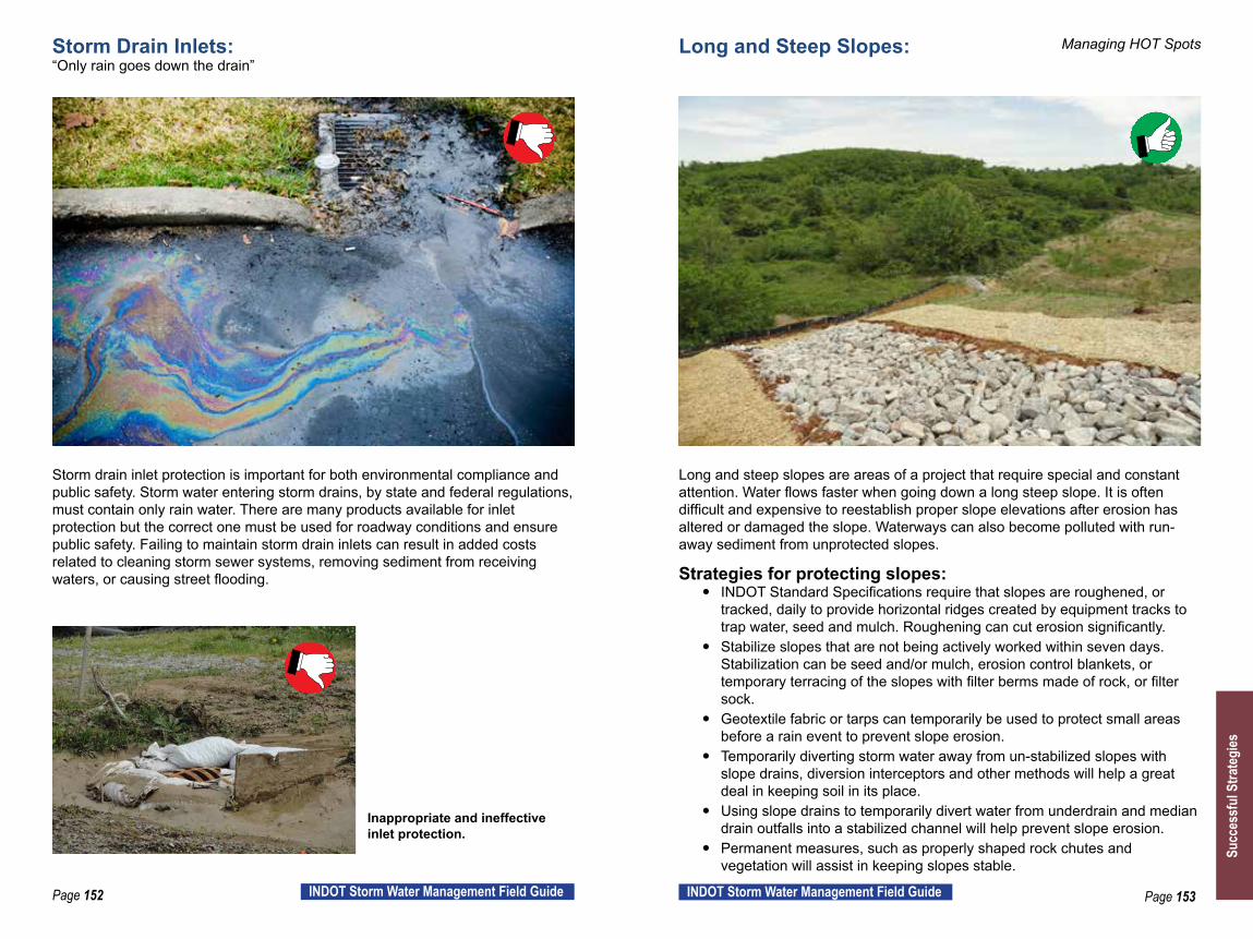
Page 152 INDOT Storm Water Management Field Guide Page 153INDOT Storm Water Management Field Guide
Storm Drain Inlets: “Only rain goes down the drain”
Storm drain inlet protection is important for both environmental compliance and public safety. Storm water entering storm drains, by state and federal regulations, must contain only rain water. There are many products available for inlet protection but the correct one must be used for roadway conditions and ensure public safety. Failing to maintain storm drain inlets can result in added costs related to cleaning storm sewer systems, removing sediment from receiving waters, or causing street flooding.
Inappropriate and ineffective inlet protection.
Long and Steep Slopes:
Long and steep slopes are areas of a project that require special and constant attention. Water flows faster when going down a long steep slope. It is often difficult and expensive to reestablish proper slope elevations after erosion has altered or damaged the slope. Waterways can also become polluted with run-away sediment from unprotected slopes. Strategies for protecting slopes:
y INDOT Standard Specifications require that slopes are roughened, or tracked, daily to provide horizontal ridges created by equipment tracks to trap water, seed and mulch. Roughening can cut erosion significantly.
y Stabilize slopes that are not being actively worked within seven days. Stabilization can be seed and/or mulch, erosion control blankets, or temporary terracing of the slopes with filter berms made of rock, or filter sock.
y Geotextile fabric or tarps can temporarily be used to protect small areas before a rain event to prevent slope erosion.
y Temporarily diverting storm water away from un-stabilized slopes with slope drains, diversion interceptors and other methods will help a great deal in keeping soil in its place.
y Using slope drains to temporarily divert water from underdrain and median drain outfalls into a stabilized channel will help prevent slope erosion.
y Permanent measures, such as properly shaped rock chutes and vegetation will assist in keeping slopes stable.
Managing HOT Spots
Succ
essf
ul S
trate
gies

Page 154 INDOT Storm Water Management Field Guide Page 155INDOT Storm Water Management Field Guide
Managing HOT SpotsGood Housekeeping:
Remember that the construction work environment is often in the public eye. Thousands of motorist may pass your project site daily. A job site that has trash blowing around, messy staging areas, leaking equipment, large areas of erosion, sediment in a waterway, unprotected stockpiles eroding, unmaintained construction entrances, and excessive dust are unacceptable situations that attract attention from the public. Often a visit from a regulatory agency is prompted by a complaint from the public.
Concrete washout not properly maintained. Trash and liquids not stored properly.
One Step Removal Process: The following is a list of requirements for the removal of silt and vegetation from “Waters of the U.S.” under the one-step removal process that does not require a permit under Section 404 of the Clean Water Act.
y One-step removal requires that sediment and debris must be removed and immediately placed landward sufficiently enough to prevent the runoff water of the dredged material from re-entering the stream/wetland.
y No dredged or fill material shall be placed below the ordinary high water mark of the stream or wetland.
y Berms or other approved methods for controlling and containing sediment should be used when the dredged material is discharged within close proximity to any “Waters of the U.S.”
y The removal of vegetation should be limited to the removal of snags, loose debris and live vegetation which obviously obstructs stream flow.
y All work, including the removal of vegetation, should be performed from one side of the channel, leaving one side undisturbed. Su
cces
sful
Stra
tegi
es

Page 156 INDOT Storm Water Management Field Guide Page 157INDOT Storm Water Management Field Guide
y The side casting of dredged material into wetlands adjacent to the stream is not allowed and would require authorization before the work is performed.
y Equipment, work areas, or access roads should not be staged within the wetland or waterway.
y Implement best management practices to ensure that the one-step removal activities being performed in “Waters of the U.S.” will not contribute to any significant degradation to the aquatic environment.
This is not acceptable under the “One Step Removal Process”.
Vegetation Establishment for NOT y Save and protect existing top soil through all phases of the project. y Protect slopes during vegetation establishment to minimize erosion. y Attach slope drain pipe to newly installed underdrains and median drain
outfalls to take storm water down to a stable ditch. y Track or roughen slopes daily or before seeding and mulching. y Mow or spray weeds, invasive plants, or other undesirable vegetation to
aid in the establishment of permanent vegetation. y Use the correct seed mix for field conditions. y Test soil. y Weed/invasive plant identification assistance (see links on back page).
Working in and around Waterways: y Make sure all correct permits have been obtained. Possible permits,
waivers and special provisions that may be required for work in and around waterways include:
y Rule 5 (for soil disturbance of .90 acres or greater). y 401/404 Permits, dredge and/or fill of streams and wetlands. y Construction in a Floodway (CIF) for work within a floodway. y Fish Spawning restrictions/waivers. y Swallows Special Provision. y Bat tree clearing restrictions.
y Use appropriate and effective BMPs in and around streams and wetlands: y Silt fence is not an appropriate BMP for use along stream banks, or
in areas prone to flooding. Fiber rolls or filter socks are better choices for perimeter control of sheet flow protection around a stream, wetland, or in a flood-prone area. If a disturbance is significant, a rock filter berm may also be needed to protect a stream or wetland.
y The most commonly used type of Erosion Control Blanket contains a plastic grid that does not degrade in areas of shade, such as under a bridge. This product is extremely dangerous to small animals living in and around the streams. There are many erosion control blanket products on the market without the plastic grid core. All efforts should be made to select the correct product for the field conditions.
y Turbidity Curtains: This BMP can only be used safely and effectively in a narrow set of conditions. The intent of this BMP is to protect stream and lake banks from sediment loss into the waterway. This BMP is difficult to install and remove and there is an increased risk of downstream issues if the product is not installed correctly. In most cases a cofferdam system should be considered instead of a turbidity curtain.
y If a pump around/dewatering system is needed for work in a stream, the designer must provide details in the plans on the set up of the system and location of key elements.
y When blown mulch is being applied around waterways, do not allow the mulch to enter the jurisdictional waterway channel or wetland.
Managing HOT Spots
Succ
essf
ul S
trate
gies

Page 158 INDOT Storm Water Management Field Guide Page 159INDOT Storm Water Management Field Guide
Silt fence does not hold its integrity in areas prone to flooding. INDOT-ES strongly recommends not using silt fence near stream banks. A filter sock is a more appropriate BMP around stream banks.
Managing HOT Spots
Blown mulch covering and clogging a jurisdictional waterway.
Filter sock and erosion control blanket together providing adequate protection for this stream bank.
Succ
essf
ul S
trate
gies
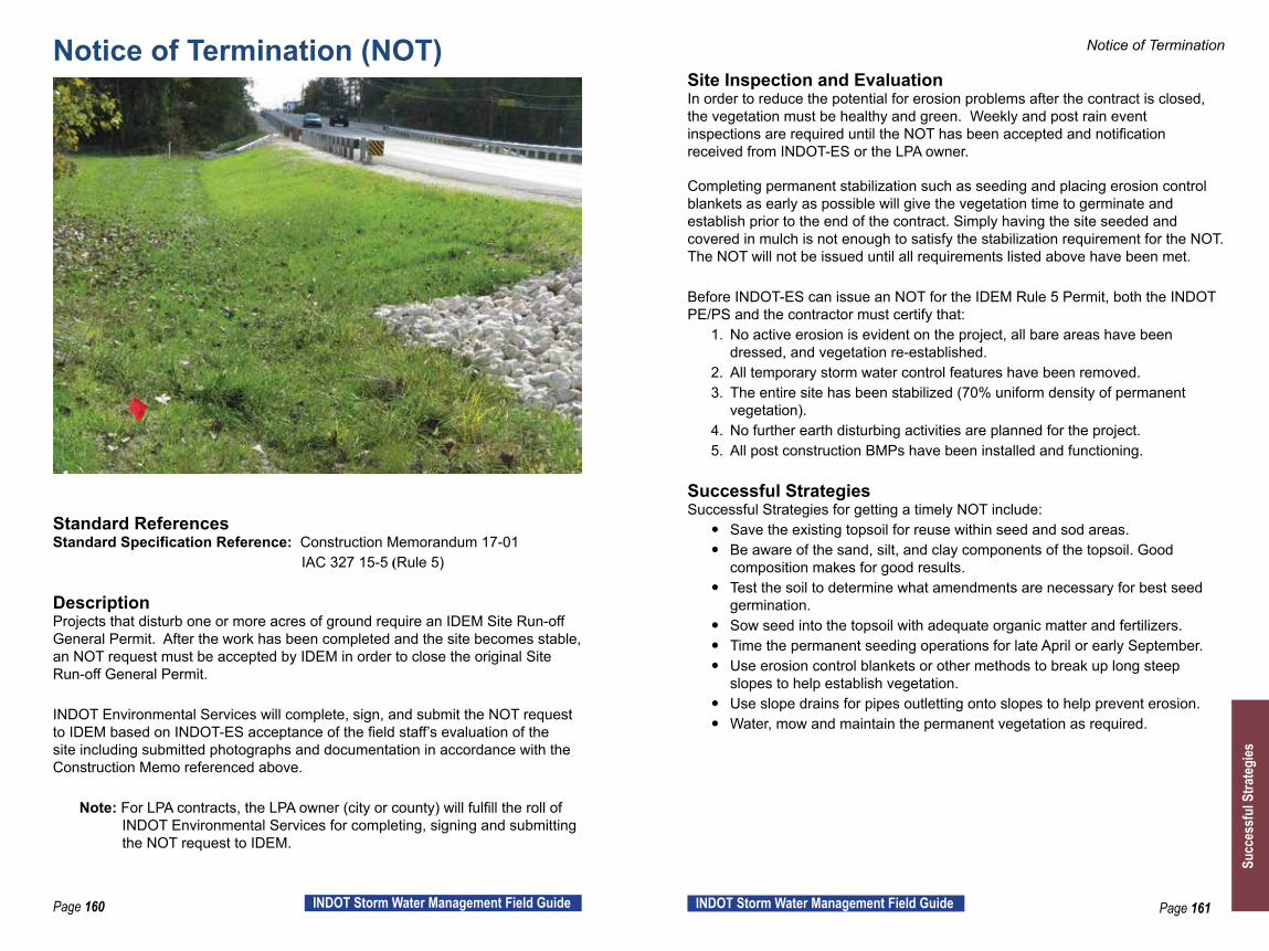
Page 160 INDOT Storm Water Management Field Guide Page 161INDOT Storm Water Management Field Guide
Notice of Termination (NOT)
Standard ReferencesStandard Specification Reference: Construction Memorandum 17-01 IAC 327 15-5 (Rule 5) DescriptionProjects that disturb one or more acres of ground require an IDEM Site Run-off General Permit. After the work has been completed and the site becomes stable, an NOT request must be accepted by IDEM in order to close the original Site Run-off General Permit.
INDOT Environmental Services will complete, sign, and submit the NOT request to IDEM based on INDOT-ES acceptance of the field staff’s evaluation of the site including submitted photographs and documentation in accordance with the Construction Memo referenced above.
Note: For LPA contracts, the LPA owner (city or county) will fulfill the roll of INDOT Environmental Services for completing, signing and submitting the NOT request to IDEM.
Notice of Termination
Site Inspection and EvaluationIn order to reduce the potential for erosion problems after the contract is closed, the vegetation must be healthy and green. Weekly and post rain event inspections are required until the NOT has been accepted and notification received from INDOT-ES or the LPA owner.
Completing permanent stabilization such as seeding and placing erosion control blankets as early as possible will give the vegetation time to germinate and establish prior to the end of the contract. Simply having the site seeded and covered in mulch is not enough to satisfy the stabilization requirement for the NOT. The NOT will not be issued until all requirements listed above have been met.
Before INDOT-ES can issue an NOT for the IDEM Rule 5 Permit, both the INDOT PE/PS and the contractor must certify that:
1. No active erosion is evident on the project, all bare areas have been dressed, and vegetation re-established.
2. All temporary storm water control features have been removed.3. The entire site has been stabilized (70% uniform density of permanent
vegetation).4. No further earth disturbing activities are planned for the project.5. All post construction BMPs have been installed and functioning.
Successful StrategiesSuccessful Strategies for getting a timely NOT include:
y Save the existing topsoil for reuse within seed and sod areas. y Be aware of the sand, silt, and clay components of the topsoil. Good
composition makes for good results. y Test the soil to determine what amendments are necessary for best seed
germination. y Sow seed into the topsoil with adequate organic matter and fertilizers. y Time the permanent seeding operations for late April or early September. y Use erosion control blankets or other methods to break up long steep
slopes to help establish vegetation. y Use slope drains for pipes outletting onto slopes to help prevent erosion. y Water, mow and maintain the permanent vegetation as required.
Succ
essf
ul S
trate
gies
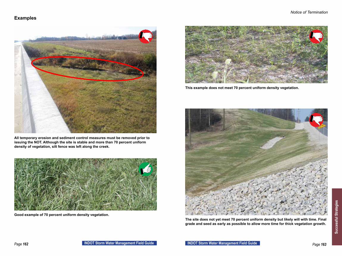
Page 162 INDOT Storm Water Management Field Guide Page 163INDOT Storm Water Management Field Guide
Examples
All temporary erosion and sediment control measures must be removed prior to issuing the NOT. Although the site is stable and more than 70 percent uniform density of vegetation, silt fence was left along the creek.
Good example of 70 percent uniform density vegetation.
This example does not meet 70 percent uniform density vegetation.
The site does not yet meet 70 percent uniform density but likely will with time. Final grade and seed as early as possible to allow more time for thick vegetation growth.
Notice of Termination
Succ
essf
ul S
trate
gies

Page 164 INDOT Storm Water Management Field Guide Page 165INDOT Storm Water Management Field Guide
NOT Process
The NOT process is outlined within Construction Memo 17-01. The steps to follow for NOT application, along with photographs depicting variations in vegetative density, are described in this section. The photos depicting vegetative density should be used to help determine whether an area is ready for an NOT request submittal.
There are three basic contract types for NOT submission:1. Single Signature Contracts – The majority of INDOT contracts are of this type.
a) PE/PS will notify Environmental Services, or the District Storm Water Specialist (DSWS) of substantial completion. A site visit to review the site may be needed.
b) The Contractor and PE/PS will evaluate the site for 70% uniform permanent vegetative density.
1. The PE/PS will document that the all five points listed within the Site Inspection and Evaluation heading (page 161) have been accomplished.
2. The PE/PS will document actual site conditions by taking photographs of turf areas. Four (4) photographs should be taken from the least vegetated areas. All photos should be taken perpendicular to the ground, taken from a standing position, and taken using a digital camera.
c) The PE/PS notifies Environmental Services of the NOT request by:
1. Email request to the Storm Water Team Leader and copy appropriate persons involved (Area Engineer (AE), Project Manager (PM), DSWS, etc.).
2. Attach documentation described in part b) above.
2. Co-signature Contracts – Design/Build contracts or contracts containing a Design/Build item for storm water management.
a) Same as step a) for Single Signature Contracts.
b) Same as step b) for Single Signature Contracts except that the PE/PS and the Contractor will jointly perform the documentation requirements.
c) The Contractor notifies Environmental Services of NOT request by:
1. Email request to the Storm Water Team Leader and copy appropriate persons involved (PE/PS, AE, DSWS, etc.).
2. Attach documentation as described in part b) of Single Signature Contracts.
3. Local Public Agency (LPA) Contracts – These contracts will follow one of the processes listed above based on the type of contract. The LPA’s designee will fulfill the role of Environmental Services.
NOT Compliance
y When Environmental Services accepts the submitted documentation for NOT compliance for Single Signature Contracts, Environmental Services will sign the NOT and notify the PE/PS and appropriate persons involved in the contract (AE, PM, DSWS, IDEM, etc.).
y When Environmental Services accepts the submitted documentation for NOT compliance for Co-Signature Contracts, Environmental Services will notify the Contractor. The Contractor shall then:
1. Prepare and sign the NOT form.
2. Deliver the signed form to Environmental Services for signature.
3. Deliver the signed form to IDEM for a date stamp.
4. Provide a hard copy of the IDEM date stamped document to Environmental Services and the PE/PS.
y If the documentation fails to achieve compliance for any type contract:
1. A field review with INDOT Environmental Services, the PE/PS, and the Contractor may be scheduled to discuss the contract and work on options to consider.
2. When the required work has been completed, resubmit a new NOT request including updated documentation.
Notice of Termination
Succ
essf
ul S
trate
gies
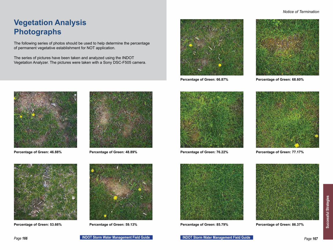
Page 166 INDOT Storm Water Management Field Guide Page 167INDOT Storm Water Management Field Guide
Notice of Termination
Percentage of Green: 46.88%
Percentage of Green: 53.66%
Percentage of Green: 68.60%
Percentage of Green: 48.89%
Percentage of Green: 59.13%
Percentage of Green: 66.87%
Percentage of Green: 76.22%
Percentage of Green: 85.79%
Percentage of Green: 77.17%
Percentage of Green: 86.37%
Vegetation Analysis PhotographsThe following series of photos should be used to help determine the percentage of permanent vegetative establishment for NOT application.
The series of pictures have been taken and analyzed using the INDOT Vegetation Analyzer. The pictures were taken with a Sony DSC-F505 camera.
Succ
essf
ul S
trate
gies
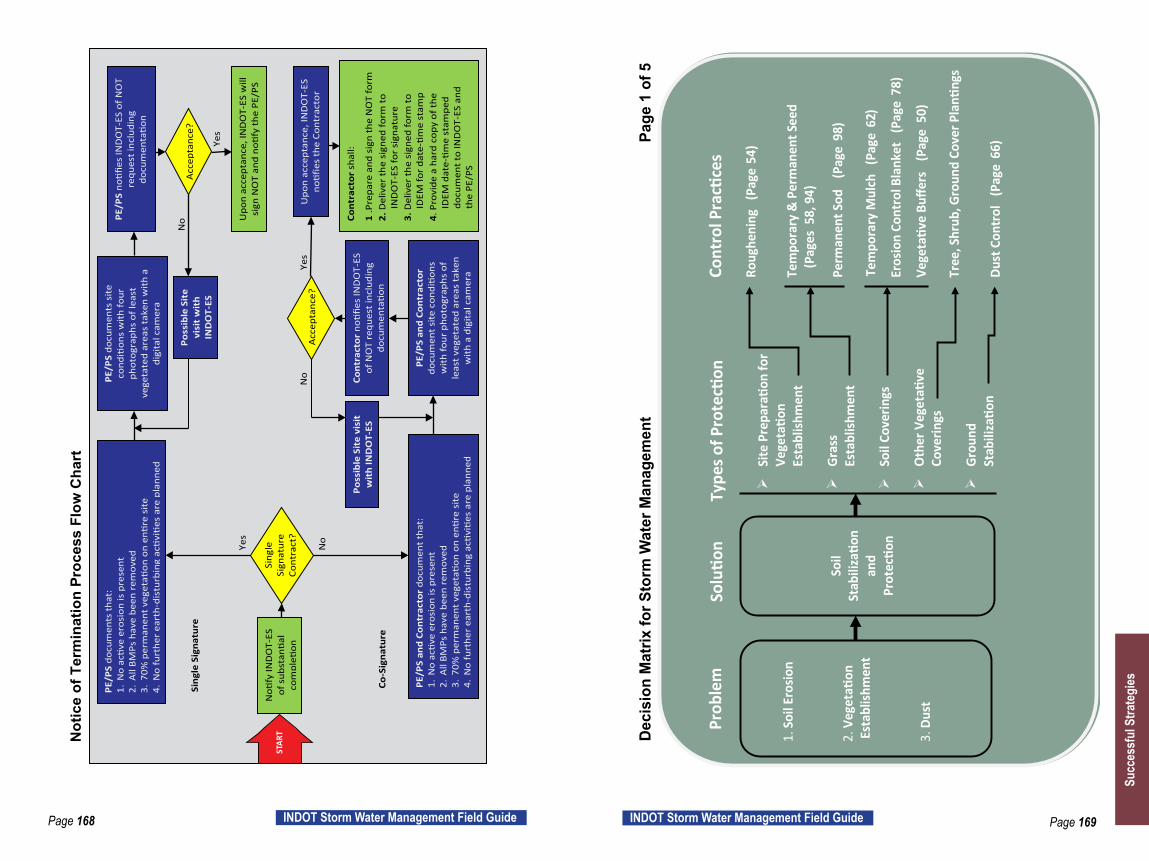
Page 168 INDOT Storm Water Management Field Guide Page 169INDOT Storm Water Management Field Guide
Site
Pre
paratio
n fo
r Ve
getatio
n Es
tabl
ishm
ent
Gras
s Es
tabl
ishm
ent
Soil
Cove
rings
O
ther
Veg
etati
ve
Cove
rings
Gr
ound
St
abili
zatio
n
1. S
oil E
rosio
n 2.
Veg
etati
on
Est
ablis
hmen
t 3.
Dus
t
So
il St
abili
zatio
n an
d Pr
otectio
n
Roug
heni
ng
(Pag
e 54
) Te
mpo
rary
& P
erm
anen
t See
d
(P
ages
58, 9
4) Pe
rman
ent S
od
(Pag
e 98
) Te
mpo
rary
Mul
ch
(Pag
e62
)
Eros
ion
Cont
rol B
lank
et
(Pag
e 78
) Ve
getativ
e Bu
ffers
(Pag
e 5
0)
Tree
, Shr
ub, G
roun
d Co
ver P
lanti
ngs
Du
st C
ontr
ol
(Pag
e 66
)
Prob
lem
So
lutio
n Ty
pes o
f Pro
tecti
on
Cont
rol P
racti
ces
Dec
isio
n M
atrix
for S
torm
Wat
er M
anag
emen
t
Page
1 o
f 5
N
otic
e of
Ter
min
atio
n Pr
oces
s Fl
ow C
hart
Noti
fy IN
DO
T-ES
of
sub
stan
tial
com
pleti
on
PE/P
S do
cum
ents
that
: 1.
No
activ
e er
osio
n is
pre
sent
2.
All
BMPs
hav
e be
en r
emov
ed
3.70
% p
erm
anen
t veg
etati
on o
n en
tire
site
4.
No
furt
her
eart
h-di
stur
bing
acti
viti
es a
re p
lann
ed
PE/P
S an
d Co
ntra
ctor
doc
umen
t tha
t:
1.N
o activ
e er
osio
n is
pre
sent
2.
All
BMPs
hav
e be
en r
emov
ed
3.70
% p
erm
anen
t veg
etati
on o
n en
tire
site
4.
No
furt
her
eart
h-di
stur
bing
acti
viti
es a
re p
lann
ed
PE/P
S do
cum
ents
site
co
nditi
ons
with
four
ph
otog
raph
s of
leas
t ve
geta
ted
area
s ta
ken
with
a
digi
tal c
amer
a
PE/P
S an
d Co
ntra
ctor
do
cum
ent s
ite c
onditio
ns
with
four
pho
togr
aphs
of
leas
t veg
etat
ed a
reas
take
n w
ith a
dig
ital c
amer
a
PE/P
S no
tifies
IND
OT-
ES o
f NO
T re
ques
t inc
ludi
ng
docu
men
tatio
n
Cont
ract
or n
otifie
s IN
DO
T-ES
of
NO
T re
ques
t in
clud
ing
docu
men
tatio
n
Upo
n ac
cept
ance
, IN
DO
T-ES
will
si
gn N
OT
and
notif
y th
e PE
/PS
Upo
n ac
cept
ance
, IN
DO
T-ES
no
tifie
s th
e Co
ntra
ctor
Cont
ract
or s
hall:
1
.Pre
pare
and
sig
n th
e N
OT
form
2.
Del
iver
the
sign
ed fo
rm to
IN
DO
T-ES
for
sign
atur
e 3.
Del
iver
the
sign
ed fo
rm to
ID
EM fo
r da
te-ti
me
stam
p 4.
Pro
vide
a h
ard
copy
of t
he
IDEM
dat
e-tim
e st
ampe
d do
cum
ent t
o IN
DO
T-ES
and
th
e PE
/PS
Yes
Sing
le
Sign
atur
e Co
ntra
ct?
Acc
epta
nce?
Acc
epta
nce?
Ye
s
Yes
No
No
Poss
ible
Sit
e vi
sit
wit
h IN
DO
T-ES
Poss
ible
Sit
e vi
sit
wit
h IN
DO
T-ES
Co
-Sig
natu
re
Sing
le S
igna
ture
No
STAR
T
Succ
essf
ul S
trate
gies

Page 170 INDOT Storm Water Management Field Guide Page 171INDOT Storm Water Management Field Guide
Chut
es a
nd D
rain
s
Di
vers
ions
So
il Co
verin
gs
4. S
lope
Ero
sion
Sl
ope
Prot
ectio
n
Slop
e Dr
ain
(Pa
ge 2
4)
Rock
Chu
te
(Pag
e 44
)
Dive
rsio
n In
terc
epto
r (P
age
40)
Roug
heni
ng
(Pag
e 54
) Fi
lter S
ock
(Pa
ge 1
24)
Te
mpo
rary
and
Per
man
ent S
eed
(Pag
es 5
8, 9
4)
Perm
anen
t Sod
(P
age
98)
Te
mpo
rary
Mul
ch
(Pag
e 62
)
Eros
ion
Cont
rol B
lank
et
(Pag
e 78
)
Prob
lem
So
lutio
n Ty
pes o
f Pro
tecti
on
Cont
rol P
racti
ces
D
ecis
ion
Mat
rix fo
r Sto
rm W
ater
Man
agem
ent
P
age
2 of
5
Ditc
h an
d O
utle
t Pr
otectio
n
St
ream
Pr
otectio
n
5. E
rosi
on in
Sw
ales
,
Ditc
hes,
Cha
nnel
s,
S
trea
ms o
r
at
O
utle
ts
6. S
trea
m
P
rote
ction
Co
ncen
trat
ed
Flow
Ero
sion
Co
ntro
l
Perm
anen
t Sod
(P
age
98)
Ro
ck C
heck
Dam
(Pa
ge 7
0)
Trav
ersa
ble
Chec
k Da
m
(Pag
e
74)
Er
osio
n Co
ntro
l Bla
nket
(Pa
ge 7
8)
Sl
ope
Drai
n (
Page
24)
Ve
getativ
e Bu
ffers
(Pag
e 5
0) Co
fferd
am
(Pag
e 2
8) Te
mpo
rary
Cro
ssin
g (
Page
138
)
Pum
p Ar
ound
(P
age
32)
Prob
lem
So
lutio
n Ty
pes o
f Pro
tecti
on
Cont
rol P
racti
ces
Dec
isio
n M
atrix
for S
torm
Wat
er M
anag
emen
t
Pag
e 3
of 5
Succ
essf
ul S
trate
gies

Page 172 INDOT Storm Water Management Field Guide Page 173INDOT Storm Water Management Field Guide
7. S
edim
ent
E
xitin
g
S
ite d
ue to
Con
stru
ction
Tru
ckin
g
Acti
vitie
s
Ro
ad
Stab
ilizatio
n
Cons
tructio
n En
tran
ce
(Pag
e 1
04)
Ti
re W
ash-
off S
tatio
n
Dust
Con
trol
(P
age
66)
Prob
lem
So
lutio
n Ty
pes o
f Pro
tecti
on
Cont
rol P
racti
ces
D
ecis
ion
Mat
rix fo
r Sto
rm W
ater
Man
agem
ent
Pa
ge 4
of 5
8. S
edim
ent
Ente
ring
Si
te
9. S
edim
ent
Exiti
ng S
ite
10. P
ollu
tant
s
in
Run
off
Se
dim
ent
Cont
rol
Dive
rsio
n In
terc
epto
r (P
age
40)
Silt
Fenc
e
(Pag
e 1
08)
Fi
lter B
erm
(P
age
120
)
Vege
tativ
e Bu
ffers
(P
age
50)
In
let P
rote
ction
(P
ages
128
, 132
)
Sedi
men
t Tra
p (
Page
112
)
Sedi
men
t Bas
in
(Pag
e 1
16)
Co
fferd
am
(Pag
e 2
8) De
wat
erin
g (
Page
36)
Tu
rbid
ity C
urta
in
Prob
lem
So
lutio
n Ty
pes o
f Pro
tecti
on
Cont
rol P
racti
ces
Sedi
men
t Bar
riers
Sedi
men
t Det
entio
n
Dec
isio
n M
atrix
for S
torm
Wat
er M
anag
emen
t
Pag
e 5
of 5
Succ
essf
ul S
trate
gies

Page 174 INDOT Storm Water Management Field Guide Page 175INDOT Storm Water Management Field Guide
Definitions
BMP – Best Management Practice. A general term used to refer to a storm water feature utilized effectively for storm water management.
Clean Water Act – Established in 1972 in order to regulate discharges of pollutants into waters of the United States and provide quality standards for the surface waters.
Contour Line – A line connecting a set of points of the same elevation on a plan view.
DSWS – District Storm Water Specialist working for INDOT.
Gravity Dewatering – Removal of water from an area using a change in grade rather than a pump.
Gully – Larger erosion channel formed as rills combine.
IDEM – Indiana Department of Environmental Management.
IDEM 401 Water Quality Certification – IDEM issued water quality permit for any person or company planning to discharge fill materials to Indiana wetlands or other water bodies by filling, excavating, open-trench cutting, or mechanical clearing.
INDOT – Indiana Department of Transportation.
INDOT-ES – Indiana Department of Transportation Environmental Services.
Jurisdictional Waterway – Also known as a “Waters of the U.S.” Generally, these are wetlands, lakes, streams, rivers, etc. that are not to be dredged, filled or otherwise altered without a permit.
Karst – Landscape features such as sinkholes, caves and underground streams formed from continually running water which dissolves limestone-like rock.
MS4 – Municipal Separate Storm Sewer Systems.
NEPA – National Environmental Policy Act. Requires federal agencies to assess environmental effects of their proposed actions prior to making decisions. Signed into law in 1970.
NOI – Notice of Intent (Rule 5). A document submitted to IDEM that includes specific project information and confirms the intent to comply with Rule 5 laws. This document should be posted at the job site.
NOS – Notice of Sufficiency (Rule 5). A letter from IDEM confirming the receipt of all NOI submittal requirements. This letter contains the permit number and expiration date and should be posted at the job site.
NOT – Notice of Termination (Rule 5). A document submitted to IDEM confirming the completion of the project, including achieving 70% permanent vegetative density, and termination of the permit.
Ordinary High Water Mark – A line on the shore indicating the fluctuations of the water level and identified by physical characteristics such as lack of vegetation, shelving, or the presence of debris.
pH – A scale from 0 to14 indicating the acidity or alkalinity of a solution. Low numbers indicate acidic substances, high numbers indicate alkaline substances. An indication of 7 is considered neutral.
Rill – Small erosion channel only a few inches in depth.
Rule 5 – Indiana state law requiring storm water management for construction activities. (327 IAC 15-5) In 2019, Rule 5 will be replaced with “Construction Site Storm Water General Permit”.
SWPPP – Storm Water Pollution Prevention Plan. The Department’s plan for storm water management for the contract.
SWQCP – Storm Water Quality Control Plan. The Contractor’s submitted plan for storm water management for the contract. The SWQCP works in conjunction with the SWPPP site conditions, and all contract documents to develop a fully functional storm water management plan for a contract.
SWQM – Storm Water Quality Manager. The individual identified by the Contractor to oversee the installation, inspection, and maintenance of all storm water management features for a contract.
Types of Water Flow:
y Sheet – Overland water moving in a continuous sheet over relatively even ground.
y Concentrated – Sheet flow will eventually collect and transition to shallow concentrated flow.
y Channel – Concentrated flow in a defined path such as a ditch bottom.
Definitions
Succ
essf
ul S
trate
gies
Page 176 INDOT Storm Water Management Field Guide Page 177INDOT Storm Water Management Field Guide
USACE – United States Army Corps of Engineers.
USACE Section 404 – Permit required for any discharge of dredged or fill material into Waters of the United States. Part of the Clean Water Act.
Velocity – The distance an object moves over a period of time. Waters of the United States – Defined in the code of federal regulations 40 CFR 230.3
Watershed – A region or area drained by a common body of water such as a stream or river.
Weir – The lowest point on a structure where water is designed to flow across.
Wetlands – An area that has been saturated with water which contains soil and plant material specific to that environment.
Definitions
Succ
essf
ul S
trate
gies

INDOT Links Project Specific Documents
http://www.in.gov/dot/div/contracts/letting/index.html
INDOT Recurring Special Provisions http://www.in.gov/dot/div/contracts/standards/rsp/index.html
INDOT Request for Approval of Borrow or Disposal Site (IC 203 R4 10/16) http://www.in.gov/dot/div/contracts/standards/forms/IC-203%20170101.pdf
INDOT Standard Drawings http://www.in.gov/dot/div/contracts/standards/drawings/index.html
INDOT Standard Specificationshttp://www.in.gov/dot/div/contracts/standards/book/index.html
General Instructions to Field Employees (GIFE) http://www.in.gov/dot/div/contracts/standards/GIFE/GIFEindex.html
INDOT Environmental Services Ecology and Waterway Permittinghttp://www.in.gov/indot/2522.htm
INDOT Environmental Services Storm Water Linkhttp://www.in.gov/indot/2892.htm
INDOT Construction Memorandums http://www.in.gov/dot/div/contracts/conmemo/con_memo.htm
INDOT Design Memorandums http://www.in.gov/dot/div/contracts/standards/memos/memos.html
LinksIDEM Emergency Response # 1-888-233-7745
http://www.in.gov/idem/files/er_quickref.pdf
Indiana Storm Water Quality Manualhttp://www.in.gov/idem/stormwater/2363.htm
IDEM Construction/Land Disturbance Permitting http://www.in.gov/idem/stormwater/2331.htm
Weed and Invasive Plant Identification https://www.entm.purdue.edu/IISC/invasiveplants.php and
http://www.inpaws.org