Incremental forming of Cu-35Zn brass alloy · ment machine was used (Figure 4), Renishaw Cyclone...
16
SI: MODELING MATERIALS AND PROCESSES, IN MEMORY OF PROFESSOR JOSÉ J. GRÁCIO Incremental forming of Cu-35Zn brass alloy Daniel Fritzen 1,2 & Anderson Daleffe 1 & Gustavo do Santos De Lucca 1 & Jovani Castelan 1 & Lirio Schaeffer 3 & Ricardo J. Alves de Sousa 2 Received: 31 January 2017 /Accepted: 25 July 2017 # Springer-Verlag France SAS 2017 Abstract Incremental Sheet Forming (ISF) and particular- ly its Single Point (SPIF) variant has been studied inten- sively over the last years given the potential for low-cost prototyping and small batches production. Numerical and experimental works have been covering a widespan of materials and geometries. This paper fills an important gap regarding studies of the SPIF process applied to brass alloys, and particularly the commonly used Cu-35Zn brass alloy. Despite being a material widely used in in- dustry for centuries, with excellent cold formability and innumerous applications, there is still no relevant infor- mation on the mechanical response and properties of this material under SPIF. This research is based in SPIF ex- periments with brass alloy sheets with different thick- nesses (0.50, 0.70 and 1.00 mm), to obtain data such as forming forces or forming fracture lines to be compared against standard forming limit diagrams or against other materials under ISF. Other data like friction during the process was evaluated as well. Fifteen sets of experiments were conducted, using different values of step down (0.10, 0.50 and 1.00 mm) and two forming tools with diameters 10 and 15 mm. Keywords Incremental Sheet Metal Forming . Cu-35Zn Brass Alloy . Forming Forces . Friction Introdution The incremental dieless forming process was described and patented by Lezak in 1967 [1], when CNC technology was still rudimentary. Only during in the 1990’ s, with the techno- logical evolution of CNC equipment, the ISF research moved on, being widely studied and developed since then [2]. From few resources (backing plate, punch and a CNC machine), it is possible to form a series of products with different geometries, allowing great design flexibility at low expenses, becoming a competitive alternative to economically and efficiently pro- duce small batches of formed products in sheet metal or other materials [3]. During the process, the sheet to be formed (blank) is clamped in a fixed support (backing plate). The simplest mo- dality of ISF, is the Single Point Incremental Forming (SPIF). Figure 1 presents the basic components of the process; (i) the sheet metal blank, (ii) the blank holder, (iii) the backing plate and (iv) the rotating (actively or passively) forming tool [4]. A simple tool (cylindrical shank with the spherical/ hemispherical tip) produces a small localized deformation on * Daniel Fritzen [email protected] * Lirio Schaeffer [email protected] * Ricardo J. Alves de Sousa [email protected] 1 SATC University, Rua Pascoal Meller, 73 - Bairro Universitário - CEP, Criciúma, SC 88805-380, Brazil 2 Center of Mechanical Technology and Automation-TEMA, Department of Mechanical Engineering, University of Aveiro, Campus Santiago, 3810-193 Aveiro, Portugal 3 Metal Forming Laboratory –LdTM, Federal University of Rio Grande do Sul – UFRGS, Av. Bento Gonçalves 9500, CP 15021, Centro de Tecnologia – Campus da Agronomia, CEP, Porto Alegre, RS 91501-970, Brazil Int J Mater Form DOI 10.1007/s12289-017-1373-4
Transcript of Incremental forming of Cu-35Zn brass alloy · ment machine was used (Figure 4), Renishaw Cyclone...
SI: MODELING MATERIALS AND PROCESSES, IN MEMORY OF PROFESSOR JOSÉ J. GRÁCIO
Incremental forming of Cu-35Zn brass alloy
Daniel Fritzen1,2&Anderson Daleffe1 &Gustavo do Santos De Lucca1 & Jovani Castelan1
&
Lirio Schaeffer3 & Ricardo J. Alves de Sousa2
Received: 31 January 2017 /Accepted: 25 July 2017# Springer-Verlag France SAS 2017
Abstract Incremental Sheet Forming (ISF) and particular-ly its Single Point (SPIF) variant has been studied inten-sively over the last years given the potential for low-costprototyping and small batches production. Numerical andexperimental works have been covering a widespan ofmaterials and geometries. This paper fills an importantgap regarding studies of the SPIF process applied to brassalloys, and particularly the commonly used Cu-35Znbrass alloy. Despite being a material widely used in in-dustry for centuries, with excellent cold formability andinnumerous applications, there is still no relevant infor-mation on the mechanical response and properties of thismaterial under SPIF. This research is based in SPIF ex-periments with brass alloy sheets with different thick-nesses (0.50, 0.70 and 1.00 mm), to obtain data such as
forming forces or forming fracture lines to be comparedagainst standard forming limit diagrams or against othermaterials under ISF. Other data like friction during theprocess was evaluated as well. Fifteen sets of experimentswere conducted, using different values of step down(0.10, 0.50 and 1.00 mm) and two forming tools withdiameters 10 and 15 mm.
Keywords IncrementalSheetMetalForming .Cu-35ZnBrassAlloy . Forming Forces . Friction
Introdution
The incremental dieless forming process was described andpatented by Lezak in 1967 [1], when CNC technology wasstill rudimentary. Only during in the 1990’s, with the techno-logical evolution of CNC equipment, the ISF research movedon, being widely studied and developed since then [2]. Fromfew resources (backing plate, punch and a CNCmachine), it ispossible to form a series of products with different geometries,allowing great design flexibility at low expenses, becoming acompetitive alternative to economically and efficiently pro-duce small batches of formed products in sheet metal or othermaterials [3].
During the process, the sheet to be formed (blank) isclamped in a fixed support (backing plate). The simplest mo-dality of ISF, is the Single Point Incremental Forming (SPIF).Figure 1 presents the basic components of the process; (i) thesheet metal blank, (ii) the blank holder, (iii) the backing plateand (iv) the rotating (actively or passively) forming tool [4]. Asimple tool (cylindrical shank with the spherical/hemispherical tip) produces a small localized deformation on
* Daniel [email protected]
* Lirio [email protected]
* Ricardo J. Alves de [email protected]
1 SATC University, Rua Pascoal Meller, 73 - Bairro Universitário -CEP, Criciúma, SC 88805-380, Brazil
2 Center of Mechanical Technology and Automation-TEMA,Department of Mechanical Engineering, University of Aveiro,Campus Santiago, 3810-193 Aveiro, Portugal
3 Metal Forming Laboratory –LdTM, Federal University of RioGrande do Sul – UFRGS, Av. Bento Gonçalves 9500, CP 15021,Centro de Tecnologia – Campus da Agronomia, CEP, PortoAlegre, RS 91501-970, Brazil
Int J Mater FormDOI 10.1007/s12289-017-1373-4

the sheet. Accordingly, the tool moves over the sheet, withgradual negative vertical increments (ΔZ), deforming thenew contact regions. Generally, the product to bemanufactured and the tool deformation path are generatedvia CAD/CAM software [5].
The peculiar bending-stretch deformation mechanism dur-ing the forming operation contributes to a higher formabilityof the sheets [6], making it a very interesting process, espe-cially for industries that require prototyping sheet metal, as theautomotive and aerospace industries. There is a vast amountof research documented in literature over the last decades,dealing with numerical and experimental approaches and cov-ering process forces, lubrication, materials, speed, materialresponse, process parameters and others. Being impossibleto cite all these works, the reader seeking for a proper intro-duction to ISF is suggested to check the state-of-art papersfrom Jeswiet and co-workers, from 2005 [3] and updated until2015 [7], as well as the paper from Reddy et al. [8], wherethey report that recently the industry renewed its interest inISF processes due to the change in consumer psychology,especially regarding the mass customization of products.
Much of the work carried out on ISF has been employingaluminium sheets, with several thickness, titanium and steelwith moderate mechanical resistance and low sheet thicknessvalues. Check reference [3] for the well-known review fromJeswiet et al., references [9–16] for references dealing mainlywith aluminium and steel and [17] for titanium. Few worksfocused on high strength steels [18], being the reason linked tothe machinery used: adapted milling machines or robots lackstiffness to promote high forming forces. With a differenttrend, brass alloys, a kind of material that shows moderate
resistance, is compatible with some aluminium alloys buthas receiving almost no attention from research groups. Fewexceptions can be found in references [19] and [20] but evenso, formability of brass alloys needs to be better characterized.
Brass and its alloys show excellent cold formality, goodcorrosion resistance and golden aspect, providing easymanufacturing of various products, such as core automotiveradiators, heat exchangers, wind musical instruments and dec-orative parts. In fact, these characteristics and features seemsto be a perfect match to ISF technology, focused on lowbatches and customized designs.
Continuing the preliminary researches conducted byFritzen et al. [21], the objective of the work is to expandthe range of materials employable within ISF, and to fillthe evident gap regarding the study of brass material re-garding its mechanical response. Summing up. this paperintroduces the use of brass alloys in the ISF research,analysing the influence of sheet thickness (t0), step down(ΔZ), forming tool diameter (DT), profile geometry andprovides Forming Fracture Lines (FFL) to give an insighton the formability of this material.
Experimental tests
For this research, the Cu - 35Zn brass alloy (SAE J463) waschosen, belonging to the same group of cartridge brass (Cu -30Zn), well-known for its excellent cold formability [22]. The
Fig. 1 Single Point IncrementalForming (SPIF) setup [4]
Table 1 Chemical composition of brass alloy Cu – 35Zn [22]
Cu Pb Fe Zn
64,00–68,50% Max. 0,15% Max. 0,05% 31,50–36,00%
Table 2 Mechanicalproperties of brass alloyCu – 35Zn [22]
Properties Value
Density 8,47 g/cm3
Young Modulus 105 GPa
Tensile Yield Stress 380 to 450 MPa
Hardness 132 HV
Int J Mater Form

chemical composition is shown in Table 1 and their mechan-ical properties in Table 2.
To better characterize the materials prior to forming, tensiletests were carried out on a universal testing machine, model
EMIC DL-10000, with 100kN capacity. Three tensile testswere carried out on 3 different direction (from rolling direc-tion, 0°, 45° and 90°). To compute Forming Limit Diagrams(FLD), a hemispherical deformation punch test (Erischsen
Fig. 2 Geometric profiles used inthe experiments: (a) PyramidalFrustums (b) Conical Frustums
Fig. 3 (a) SPIFA machine; (b)Forming conical frustum Cu –35Zn brass alloy
(a)
(b)
(c)
Fig. 4 Geometric Analysis: (a)CNC coordinate measurementmachine; (b) Detail of contactprobe and measuring area; (c)Three-dimensional file generatedby measurement
Int J Mater Form
test) was employed, per ASTM E 2218–04. Both tests wereperformed on the three sheet thicknesses to be used with SPIF.
For SPIF experiments, conical and pyramidal frustums ge-ometries were considered, according to the models used bySurresh and Regalla [16], in blanks of 150 mm × 150 mm, and0.50, 0.70 and 1.00 mm thick (t0), with radial profile wall(50 mm radius), diameter 100 mm and square 100 mm, re-spectively (Figure 2). The forming tool was also heat treated,resulting in an increased hardness to 58HRc. The tool geom-etry consists on a spherical tip with 10 and 15 mm diameter.The trajectory performed by the tool consists in the 3-axiscontour tool path, with vertical increments (ΔZ) of 0.10,0.50 and 1.00 mm. The forming tool has passive rotation, asdescribed in [3] and average travel velocity (feed rate) of3000 mm/min. For the lubrication of the incremental formingprocess, mineral oil was used (Repsol SAE 30, [14]).
The 3DCADmodels weremade in SolidWorks® software,while the CNC program for ISF, in EdgeCAM® software.
Although it is already proven in investigations about theSPIF process that the helical strategy is more adequate, be-cause it decomposes the vertical Increment (ΔZ) along allcontour, and produces a better surface finish than the contourstrategy [8], for the experiments of this investigation, the con-tour strategy – localized vertical Increment (ΔZ) –was chosento analyse the behaviour of the vertical force (FZ) during theSPIF process.
The experiments were performed in the SPIF-A ma-chine [23], developed specifically for incremental sheetforming (Figure 3). This machine has six independent de-grees of freedom driven by hydraulic actuators. The ma-chine withstands compressive and lateral loads and of 13kN and 6.5 kN, respectively. The SPIF-A has three tri-axialload-cells placed between the spindle and mobile base ofthe Stewart platform.
To analyse the true strains (ε1, ε2), electrochemicaletching was made using a grid of circles (Ø2,75 mm)
0
50
100
150
200
250
300
350
400
450
500
0.0
0
0.0
2
0.0
4
0.0
6
0.0
8
0.1
0
0.1
2
0.1
4
0.1
6
0.1
8
0.2
0
0.2
2
0.2
4
0.2
6
0.2
8
0.3
0
0.3
2
0.3
4
0.3
6
0.3
8
0.4
0
Stre
ss σ
[MPa
]
Strain Ԑ [%]
0.5 mm 0.7 mm 1.0 mm
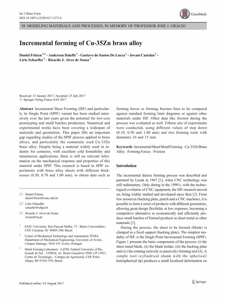
Fig. 5 Flow curve of Brass AlloyCu-35Zn at rolling direction
Fig. 6 Dimensions of thespecimens (CP: Specimennumber)
Fig. 7 Nakajima test and results
Int J Mater Form

on the surface of each tested sheet. Measurements wereperformed with a digital stereoscope. The determinationof the maximum wall angle (ψ) was carried out basedon the maximum depth reached. For the analysis of thegeometric profile, and consequently, the depth of frac-ture (DP), a three-dimensional CNC coordinate measure-ment machine was used (Figure 4), Renishaw CycloneSeries 2, precision 0.005 mm. At the end of each
measurement process, a CAD file (DXF) is generated(c), making possible the comparative analysis of theformed geometries against the designed one. In addition,the final thicknesses of the sheets were measured, usingan external micrometer (Mitutoyo, resolution 0,01 mm).Finally, friction was computed as the ratio between ra-dial and vertical forces, as in the classical sliding fric-tion definition [14].
0.00
0.05
0.10
0.15
0.20
0.25
0.30
0.35
0.40
0.45
0.50
0.55
0.60
-0.25 -0.20 -0.15 -0.10 -0.05 0.00 0.05 0.10 0.15
Maj
or
Str
ain
1
[-]
Minor Strain 2 [-]
Forming Limit Diagram - FLD
FLD_0.50 FLD_0.70 FLD_1.00
Fig. 8 FLD for differentthickness of Cu-35Zn Brass Alloy
0.00
400.00
800.00
1,200.00
0.00 6.00 12.00 18.00 24.00 30.00 36.00
Forc
e (F
) [
N]
Depth of the experiment [mm]
Fz_FP_D10 Fz_FC_D10 Fz_FP_D15 Fz_FC_D15
Fxy_FP_D10 Fxy_FC_D10 Fxy_FP_D15 Fxy_FC_D15
Fig. 9 Forming Force SPIFBrass: ΔZ = 1.00 mm |t0 = 0.50 mm
Int J Mater Form

Results
Characterization of the brass sheets
As an initial reference, Fig. 5 present the flow curve of Cu-35Zn Brass Alloy, for the 3 different thickness values understudy. Rolling direction was considered. Peforming a fittingprocedure using the Swift law (σ = Kεn), yields hardeningparameters n of 0.26, 0.22 and 0.19 for the 0.5 mm, 0.7 mmand 1.0 mm sheets respectively.
Forming Limit Diagramswere computed aswell. Similarly, totensile tests, FLDs were computed for 3 thickness values understudy, Fig. 8. Computing a FLD begins with the experimentaltests, where specimens with different widths are cut (Figure 6).
Then, the specimens are properly fixed in a backing plateand subjected to the hemispherical punch action until theirrupture. The ε1 vs ε2 graphs were elaborated from the well-known procedure [24] based on Nakajima test (Figure 7).
The curves presented in Fig. 8 reveal a better formabilityfor the thinner sheet (0.50 mm, n = 0.26) and a worse one for
0.00
400.00
800.00
1,200.00
0.00 6.00 12.00 18.00 24.00 30.00 36.00
Fo
rce
(F)
[-]
Depth of the experiment [mm]
Fz_FP_D10 Fz_FC_D10 Fz_FP_D15 Fz_FC_D15
Fxy_FP_D10 Fxy_FC_D10 Fxy_FP_D15 Fxy_FC_D15
Fig. 11 Forming Force SPIFBrass: ΔZ = 0.10 mm |t0 = 0.50 mm
0.00
400.00
800.00
1,200.00
1,600.00
0.00 6.00 12.00 18.00 24.00 30.00 36.00
Fo
rce
(F)
[N]
Depth of the experiment [mm]
Fz_FP_D10 Fz_FC_D10 Fz_FP_D15 Fz_FC_D15
Fxy_FP_D10 Fxy_FC_D10 Fxy_FP_D15 Fxy_FC_D15
Fig. 12 Forming Force SPIFBrass: ΔZ = 1.00 mm |t0 = 0.70 mm
0.00
400.00
800.00
1,200.00
0.00 6.00 12.00 18.00 24.00 30.00 36.00
Fo
rce
(F)
[-]
Depth of the experiment [mm]
Fz_FP_D10 Fz_FC_D10 Fz_FP_D15 Fz_FC_D15
Fxy_FP_D10 Fxy_FC_D10 Fxy_FP_D15 Fxy_FC_D15
Fig. 10 Forming Force SPIFBrass: ΔZ = 0.50 mm |t0 = 0.50 mm
Int J Mater Form

the thicker (1.00 mm, n = 0.19), which comes in agreementwith the computed flow curves (higher Bn^parameter for the0.5 mm sheet).
Despite the undeniable utility of FLDs under conventionalpress-forming, they reveal inefficient for incremental formingoperation, given the diffuse necking phenomenon prior tofracture [4]. For this reason, Fracture Forming Lines (FFL)were computed and presented in BForming Forces of BrassAlloy Sheets with SPIF^ section.
Forming forces of brass alloy sheets with SPIF
Using the referred SPIF-A machine and the two proposedgeometries, forming forces were acquired using 3D load cells.Compressive, vertical (FZ), and radial, resultant on XY plane(FXY) are presented with the following results (Figs. 9, 10, 11,12, 13, 14, 15, 16 and 17). For easier inspection, data is orga-nized and presented considering step down (ΔZ) and sheetthickness (t0). The following abbreviations also apply:
0.00
400.00
800.00
1,200.00
1,600.00
0.00 6.00 12.00 18.00 24.00 30.00 36.00
Fo
rça
(F)
[N
]
Profundidade do Experimento [mm]
Fz_FP_D10 Fz_FC_D10 Fz_FP_D15 Fz_FC_D15
Fxy_FP_D10 Fxy_FC_D10 Fxy_FP_D15 Fxy_FC_D15
Fig. 14 Forming Force SPIFBrass: ΔZ = 0.10 mm |t0 = 0.70 mm
0.00
400.00
800.00
1,200.00
1,600.00
2,000.00
2,400.00
0.00 6.00 12.00 18.00 24.00 30.00 36.00
Forc
e (F
) [
N]
Depth of the experiment [mm]
Fz_FP_D15 Fz_FC_D15 Fxy_FP_D15 Fxy_FC_D15
Fig. 15 Forming Force SPIFBrass: ΔZ = 1.00 mm |t0 = 1.00 mm
0.00
400.00
800.00
1,200.00
1,600.00
0.00 6.00 12.00 18.00 24.00 30.00 36.00
Fo
rce
(F)
[N]
Depth of the experiment [mm]
Fz_FP_D10 Fz_FC_D10 Fz_FP_D15 Fz_FC_D15
Fxy_FP_D10 Fxy_FC_D10 Fxy_FP_D15 Fxy_FC_D15
Fig. 13 Forming Force SPIFBrass: ΔZ = 0.50 mm |t0 = 0.70 mm
Int J Mater Form

& FZ and FXY refers to the measured force component;& FC and FP refers to the geometry: Frustum: Conical and
Frustum: Pyramidal, respectively;& D10 and D15 refers to the forming tool diameter (DT);
From the results presented from Fig. 9, 10, 11, 12, 13, 14, 15,16 and 17 it can be inferred a similar trend for FZ and FXY com-ponents, i.e., they increase along with the forming depth (andconsequently higher wall angle), for both geometries studied.
0.00
400.00
800.00
1,200.00
1,600.00
2,000.00
0.00 6.00 12.00 18.00 24.00 30.00 36.00
Fo
rce
(F)
[N
]
Depth of the experiment [mm]
Fz_FP_D15 Fz_FC_D15 Fxy_FP_D15 Fxy_FC_D15
Fig. 16 Forming Force SPIFBrass: ΔZ = 0.50 mm |t0 = 1.00 mm
0.00
400.00
800.00
1,200.00
1,600.00
0.00 6.00 12.00 18.00 24.00 30.00 36.00
Fo
rce
(F)
[N
]
Depth of the experiment [mm]
Fz_FP_D15 Fz_FC_D15 Fxy_FP_D15 Fxy_FC_D15
Fig. 17 Forming Force SPIFBrass: ΔZ = 0.10 mm |t0 = 1.00 mm
1,0
04
.85
99
8.8
6
83
3.1
1
92
9.8
3
84
5.3
3
84
8.4
2
83
6.6
8
86
2.3
5
71
9.6
3
76
4.7
0
58
5.8
9
62
0.8
2
1,5
01
.85
1,5
65
.00
1,2
24
.19
1,2
51
.10
1,0
18
.31
1,0
52
.52
1,2
63
.32
1,3
03
.00
1,0
26
.79
1,0
45
.32
75
6.3
7
79
4.9
3
1,9
47
.25
2,0
59
.10
1,5
67
.45
1,6
22
.21
1,2
67
.45
1,2
90
.81
0
500
1,000
1,500
2,000
2,500
FC
_P
1.0
_S
0.5
_D
15
FP
_P
1.0
_S
0.5
_D
15
FC
_P
0.5
_S
0.5
_D
15
FP
_P
0.5
_S
0.5
_D
15
FC
_P
0.1
_S
0.5
_D
15
FP
_P
0.1
_S
0.5
_D
15
FC
_P
1.0
_S
0.5
_D
10
FP
_P
1.0
_S
0.5
_D
10
FC
_P
0.5
_S
0.5
_D
10
FP
_P
0.5
_S
0.5
_D
10
FC
_P
0.1
_S
0.5
_D
10
FP
_P
0.1
_S
0.5
_D
10
FC
_P
1.0
_S
0.7
_D
15
FP
_P
1.0
_S
0.7
_D
15
FC
_P
0.5
_S
0.7
_D
15
FP
_P
0.5
_S
0.7
_D
15
FC
_P
0.1
_S
0.7
_D
15
FP
_P
0.1
_S
0.7
_D
15
FC
_P
1.0
_S
0.7
_D
10
FP
_P
1.0
_S
0.7
_D
10
FC
_P
0.5
_S
0.7
_D
10
FP
_P
0.5
_S
0.7
_D
10
FC
_P
0.1
_S
0.7
_D
10
FP
_P
0.1
_S
0.7
_D
10
FC
_P
1.0
_S
1.0
_D
15
FP
_P
1.0
_S
1.0
_D
15
FC
_P
0.5
_S
1.0
_D
15
FP
_P
0.5
_S
1.0
_D
15
FC
_P
0.1
_S
1.0
_D
15
FP
_P
0.1
_S
1.0
_D
15
Max
.For
ce (F
) [N
]
SPIF experiments [-]
Fig. 18 All Forming Forces SPIF Brass
Int J Mater Form

Additionally, it is also possible to observe smaller force (FZand FXY) values in the experiments with smaller tool tip (Ø10mm). In fact, the smaller the tool, the more localized is thedeformation. According to Martins et al. [4], as the diameterof the forming tool increases, themore similar is themechanicalresponse under ISF with the conventional forming process.
In Azevedo et al. [14] researches, the Forces (FZ and FXY)of two different materials are analysed, the AA1050 alumini-um alloy and DP780 steel alloy, both with 1 mm thickness,and although there is a great difference in the collected forces
(350 N and 1500 N, respectively), there is similarity in thecurves’ trend. Curves obtained from the brass sheets are sim-ilar, showing that brass has a compatible response.
To illustrate the magnitude of Vertical Forces (FZ) in SPIFprocess, Fig. 18 shows the maximum values of forces analysedat each experiment, separated according to their thicknesses.
The two geometric forms analysed showed similarity in themaximum values of Vertical Forces (FZ). Also, it is observedthat the maximum forces decrease for smaller step down (ΔZ)values.
0.00
0.10
0.20
0.30
0.40
0.50
0.00 6.00 12.00 18.00 24.00 30.00 36.00
Fri
ctio
n
()
[-]
Depth of the experiment [mm]
FP_D10 FC_D10 FP_D15 FC_D15
Fig. 19 Friction SPIF Brass:ΔZ = 1.00 mm | t0 = 0.50 mm
0.00
0.10
0.20
0.30
0.40
0.50
0.00 6.00 12.00 18.00 24.00 30.00 36.00
Fri
ctio
m (
) [-
]
Depth of the experiment [mm]
FP_D10 FC_D10 FP_D15 FC_D15
Fig. 20 Friction SPIF Brass:ΔZ = 0.50 mm | t0 = 0.50 mm
0.00
0.10
0.20
0.30
0.40
0.00 6.00 12.00 18.00 24.00 30.00 36.00
Fri
ctio
m (
) [-
]
Depth of the experiment [mm]
FP_D10 FC_D10 FP_D15 FC_D15
Fig. 21 Friction SPIF Brass:ΔZ = 0.10 mm | t0 = 0.50 mm
Int J Mater Form

Following the same form of organization of the force re-sults, friction effects (μ) are presented from Figs. 19, 20, 21,22, 23, 24, 25, 26 and 27.
Since the friction values (μ) are calculated in function ofthe Forces (FZ and FXY). Naturally, friction values (μ) comingfrom the Ø15 mm forming tool experiments are greater thanthe Ø10 mm tool ones, once the contact area is larger.
A relation between the friction value (μ) and the initial sheetthickness (t0) is verified. In fact, for the higher thicknesses(1.0 mm), the friction evolution during the process is roughly
monotonically crescent, almost linear. As sheet thickness goesto 0.5 mm and 0.7 mm such evolution tends to be non-linear.
Formability and geometrical accuracy
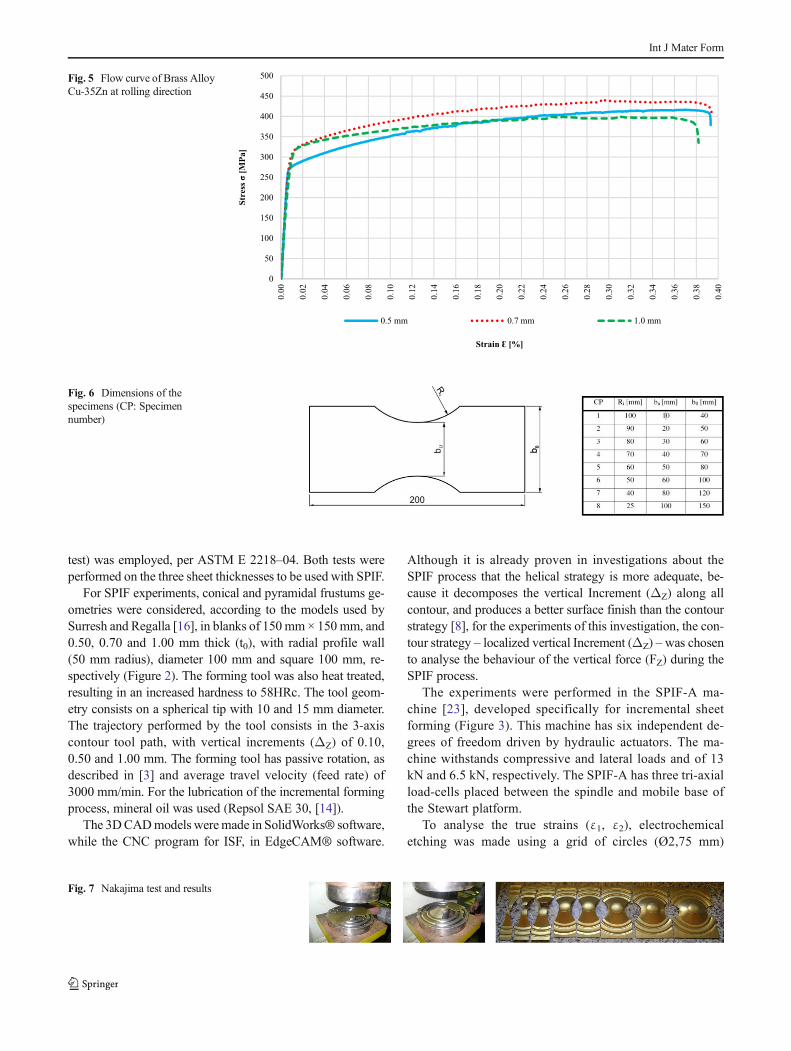
All measurements from SPIF made geometries were per-formed at the rolling direction (0°). Figure 28 compares themeasured profiles against the CAD geometry.
Geometrical inaccuracy is still one of the major drawbacksin ISF operations. Based on Fig. 28, it is observed that none of
0.00
0.10
0.20
0.30
0.40
0.50
0.00 6.00 12.00 18.00 24.00 30.00 36.00
Fri
ctio
m (
) [-
]
Depth of the experiment [mm]
FP_D10 FC_D10 FP_D15 FC_D15
Fig. 22 Friction SPIF Brass:ΔZ = 1.00 mm | t0 = 0.70 mm
0.00
0.10
0.20
0.30
0.40
0.50
0.00 6.00 12.00 18.00 24.00 30.00 36.00
Fri
ctio
m (
m)
[-]
Depth of the experiment [mm]
FP_D10 FC_D10 FP_D15 Fxy_FC_D15
Fig. 23 Friction SPIF Brass:ΔZ = 0.50 mm | t0 = 0.70 mm
0.00
0.10
0.20
0.30
0.40
0.50
0.00 6.00 12.00 18.00 24.00 30.00 36.00
Fri
ctio
m (
) [-
]
Depth of the experiment [mm]
FP_D10 FC_D10 FP_D15 FC_D15
Fig. 24 Friction SPIF Brass:ΔZ = 0.10 mm | t0 = 0.70 mm
Int J Mater Form

the SPIF profiles measured match the designed part. All ofthem show geometrical deviations.
Such deviations corroborate with Allwood et al. [25] (ormany other authors), where it is reported that acceptable di-mensional tolerances for sheet metal components are normally±0.2 mm, however for conventional ISF processes dimension-al accuracy is only ±3 mm. Another fact refers to the depthsreached on each SPIF experiment. According to Martins et al.[4], the use of forming tools with smaller diameter (DT) pro-vides better formability because the stress concentrations are
in a smaller region of deformation of the sheet. In Fig. 27 ispossible to observe that the experiments with tool Ø10 mmobtained the greatest depths, as also observed by Centenoet al. [13].
At the lateral flaps, restrained during forming operation bythe blank holder, there was a significant amount of deforma-tion. Allwood et al. [25] and Ambrogio et al. [26] describedthis behaviour of the sheet as resulting from the accumulation(and relaxation) of residual stresses, appearing after the releaseof the blank holder.
0.00
0.10
0.20
0.30
0.40
0.50
0.60
0.00 6.00 12.00 18.00 24.00 30.00 36.00
Fri
ctio
m (
) [-
]
Depth of the experiment [mm]
FP_D15 FC_D15
Fig. 25 Friction SPIF Brass:ΔZ = 1.00 mm | t0 = 1.00 mm
0.00
0.10
0.20
0.30
0.40
0.50
0.00 6.00 12.00 18.00 24.00 30.00 36.00
Fri
ctio
m (
) [-
]
Depth of the experiment [mm]
FC_D15 FP_D15
Fig. 26 Friction SPIF Brass:ΔZ = 0.50 mm | t0 = 1.00 mm
0.00
0.10
0.20
0.30
0.40
0.00 6.00 12.00 18.00 24.00 30.00 36.00
Fri
ctio
m (
) [-
]
Depth of the experiment [mm]
FP_D15 FC_D15
Fig. 27 Friction SPIF Brass:ΔZ = 0.10 mm | t0 = 1.00 mm
Int J Mater Form
All the experiments performed suffered a fracture in thesame region, which lays in the contact zone of the tool withthe sheet. Figure 29 shows two fractured SPIF experiments.Once fracture is initiated, and given the diffuse necking andhigh stress concentration, it quickly spreads.
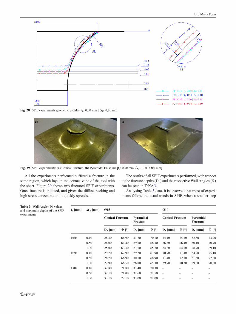
The results of all SPIF experiments performed, with respectto the fracture depths (DF) and the respective Wall Angles (Ψ)can be seen in Table 3.
Analysing Table 3 data, it is observed that most of experi-ments follow the usual trends in SPIF, when a smaller step
Fig. 28 SPIF experiments geometric profiles: t0: 0,50 mm | ΔZ: 0,10 mm
Fig. 29 SPIF experiments: (a) Conical Frustum, (b) Pyramidal Frustums [t0: 0.50 mm| ΔZ: 1.00 | Ø10 mm]
Table 3 Wall Angle (Ψ) valuesand maximum depths of the SPIFexperiments
t0 [mm] ΔZ [mm] Ø15 Ø10
Conical Frustum PyramidalFrustum
Conical Frustum PyramidalFrustum
DF [mm] Ψ [°] DF [mm] Ψ [°] DF [mm] Ψ [°] DF [mm] Ψ [°]
0.50 0.10 28,30 66,90 31,20 70,10 34,10 75,10 32,50 73,20
0.50 26,00 64,40 29,50 68,30 26,30 66,40 30,10 70,70
1.00 25,00 63,30 27,10 65,70 24,80 64,70 28,70 69,10
0.70 0.10 29,20 67,90 29,20 67,90 30,70 71,40 34,20 75,10
0.50 28,20 66,90 30,10 68,90 31,40 72,10 31,50 72,30
1.00 27,90 66,50 26,80 65,30 29,70 70,30 29,80 70,30
1.00 0.10 32,80 71,80 31,40 70,30 - - - -
0.50 32,10 71,00 32,60 71,50 - - - -
1.00 33,10 72,10 33,00 72,00 - - - -
Int J Mater Form

down (ΔZ) leads to higher depths and wall angles, corrobo-rating [4, 13]. Figure 30 translate the previous table into agraphical form.
It is possible to check that four experiments do not followthe usual tendency. In the set of experiments 06 (t0: 0.70 mm |Ø15 mm | Pyramidal Frustum) the higher depth is observedfor a 0.50 mm step down. The same was observed in experi-ments 07 (t0: 0.70 mm | Ø10 mm | Conical Frustum). Sinceexperiments number 06 (Pyramid) and number 05 (Cone)were performed under the same parameters, such differencesmight be related with the distinct geometries performed.
Finally, an inverted max. Depth evolution is observed forexperiments number 09 (t0: 1.00 mm | Ø15 mm | ConicalFrustum) and number 10 (t0: 1.00 mm | Ø15 mm |
Pyramidal Frustum), where higher depths were obtained withthe higher step-down of 1.00 mm.
The final thicknesses (t1) of each experiment were alsoanalysed, to verify the validity of the Sine Law during SPIFwith brass alloys. Figure 31 shows the lowest final thicknessvalues (t1) measured (near the fractured region in the formedarea) compared to the values calculated by Sine Law, as afunction of the Wall Angle (Ψ), listed in Table 3.
Naturally, analysing the data on Fig. 31, it is noticed thatthe lower the initial thickness (t0) of the sheet, the lower var-iation of the measured and calculated values. In fact, thehigher the thickness, the higher will be forming forces, shearstrains and resulting stresses, which will lead to more pro-nounced deviations. Table 4 groups the values according to
28
.30
31
.20
34
.10
32
.50
29
.20
29
.20
30
.70
34
.20
32
.40
30
.40
26
.00
29
.50
26
.30
30
.10
28
.20
31
.90
33
.80
31
.50
32
.80
32
.60
25
.00
27
.10
24
.80
28
.70
27
.90
26
.80
29
.70
29
.80 35
.90
33
.00
0.00
10.00
20.00
30.00
40.00
50.00
Cone
Frustum
Pyramid
Frustum
Cone
Frustum
Pyramid
Frustum
Cone
Frustum
Pyramid
Frustum
Cone
Frustum
Pyramid
Frustum
Cone
Frustum
Pyramid
Frustum
Ø15 | t0 = 0.50 mm Ø10 | t0 = 0.50 mm Ø15 | t0 = 0.70 mm Ø10 | t0 = 0.70 mm Ø15 | t0 = 1.00 mm
Dep
th (D
F) [m
m]
Experiments [-]
Depth Fracture (DF) vs Vertical Increment ( Z)
0.10 mm 0.50 mm 1.00 mmZ:
Fig. 30 Values of maximum depths reached in all experiments
0.00
0.10
0.20
0.30
0.40
0.50
0.60
Thic
knes
s (t
1)
[mm
]
SPIF Experiment [-]
Thickness (t1) SPIF experiment
Sine Law t1 [mm]
Fig. 31 Lower values of final thickness (t1) measured in the experiments
Int J Mater Form

the initial thickness of the sheets. The values calculated by theSine Law point to a reduction of 62% to 68% of the thicknessof the sheet, while for the measured values is between 51%and 55%.
Finally, Fracture Forming Lines were elaborated, afteranalysing the deformations (ε1 and ε2) of the circle grid(turned into ellipses) near the fractured regions, for the varietyof geometries studied, including not only frustrum-type geom-etries, but also constant slope cones and pyramids, With themeasurement of the ellipses in the SPIF experiments, it wasobserved that the calculated values of the deformations (ε1 andε2) are very close, independent of the forming tool diameter(DT). Contrarily, the Vertical Increment (Δz) yields differentfracture lines.
Figure 32 shows the analysed deformations of SPIF exper-iments with t0: 0.50 mm thickness, respective FFLs and FLDfor comparison purposes.
As reported for instance by Jeswiet et al. [3], the small-er the step down (Δz) used in the ISF process, the greaterthe material formability in ISF. Figure 32 portrays precise-ly this aspect, where the major strain for 0.10 mm stepdown is circa 0,75, while for 1.00 mm, is reduced to 0,63,but still higher than in the FLD. Figure 33 shows theanalysed deformations of SPIF experiments with t0:0.70 mm thickness.
In Fig. 33, the same behaviour of the resulting FFL isobserved, with the highest deformations corresponding tothe lowest step down (ΔZ = 0.10 mm), and in this case,with similar values to the FFL of Fig. 32. The FFL withstep down 1.00 mm is slightly below the FFL of Fig. 32,while the FFL with the step down of 0.50 mm slightlyhigher.
Figure 34 shows the analysed deformations of SPIF exper-iments with t0: 1.00 mm thickness.
0.00
0.05
0.10
0.15
0.20
0.25
0.30
0.35
0.40
0.45
0.50
0.55
0.60
0.65
0.70
0.75
0.80
0.85
0.90
0.95
1.00
-0.25 -0.20 -0.15 -0.10 -0.05 0.00 0.05 0.10 0.15
Maj
or
Str
ain
(
1)
[-]
Minor Strain ( 2) [-]
FLD FFL_P0.10 FFL_P0.50 FFL_P1.00
Fig. 32 Fracture Forming Lines (t0: 0,50 mm)
Table 4 Values of the Sine Lawand the values measured in thefinal thickness (t1) of the sheet
t0[mm]
Sine Law [mm] s1 [mm]
Averagevalue
Standarddeviation
Thicknessreduction
Averagevalue
Standarddeviation
Thicknessreduction
0,50 0,19 0,03 62,86% 0,25 0,02 51,00%
0,70 0,24 0,03 65,14% 0,33 0,04 53,57%
1,00 0,32 0,05 68,19% 0,44 0,07 55,83%
0.00
0.05
0.10
0.15
0.20
0.25
0.30
0.35
0.40
0.45
0.50
0.55
0.60
0.65
0.70
0.75
0.80
0.85
0.90
0.95
1.00
-0.25 -0.20 -0.15 -0.10 -0.05 0.00 0.05 0.10 0.15
Maj
or
Str
ain
(1)
[-]
Minor Strain ( 2) [-]
FLD FFL_P1.00 FFL_P0.50 FFL_P0.10
Fig. 33 Fracture Forming Line (t0: 0.70 mm)
Int J Mater Form

Similarly, to previous FFLs, the smallest step down pro-duces the largest deformations. However, for this 1.00 mmthick brass sheet, the influence of step down is clearly re-duced. Hence, the thicker the sheet the lower the beneficialeffect of step-down in formability.
Common to all FFL graphs is the clear formability im-provement when compared to FLD for the same thickness.So, the improved formability of ISF also hold for brass alloys.
The maximum values of major strain (ε1) are close for thethree thicknesses values studied, indicating a maximum defor-mation limit for this material (in these experimentalconfigurations).
Conclusions
Currently, research on incremental forming technology hasbeen focusing more usually on aluminium material, and alsoon steel and titanium alloys.
This work focused on brass alloys, a noble material, thatdespite being pricey, is traditionally applied in decoration,ornaments or custommade parts. In this sense, ISF technologyhas a huge potential to shape brass sheets at an affordable pricefor customized products.
The experiments showed that the brass alloy studiedshowed a regular, expected performance under SPIF whencompared with other already documented materials. In this
sense, formability is increased with the FFL appearing abovethan the conventional FLC of the material. The formabilityimprovement is more pronounced for smaller tool diameters,a phenomenon also reported in literature for other materials.Doing so, the highest wall angles for the 2 geometries studiedwere obtained for the 10 mm diameter tool. Regarding wallthickness reduction, the sine law was fairly followed. In thestudied cases, the law pointed for thickness reduction between62% and 68% but the measured values situated between 51%and 55%. Forming forces were kept at acceptable levels andevolving like expected on SPIF operations.
Regarding ISF processing parameters, it can be inferred asignificant effect of step down size. Like other materials,higher step down sizes will imply large forming forces andworse surface finish. Likewise, higher sheet thicknesses andlarger tool diameters will increase forming forces.Dimensional inaccuracy is also a barrier for brass alloys underSPIF, with the measured formed geometries presenting devi-ations when compared to the designed CAD (± 3 mm), com-patible to values reported in literature for aluminium. In thissense, much of work carried out by other groups regardingoptimized toolpaths can be perfectly employed to brassmaterials.
Summing up, this paper documented the mechanical re-sponse of brass alloy sheets under incremental forming, fillinga gap in the literature. The material shows compatible proper-ties when compared to other types of materials commonlyused in ISF and proves that brass alloys can be easilyemployed in this low batches, highly customizable technique.
Acknowledgments The authors thank National Council of ScientificDevelopment – CNPq (Process 234851/2014-7) for financial support indeveloping this project; UFRGS/LdTM, University of Aveiro, Center ofMechanical Technology and Automation (TEMA), North AveiroPolytechnic School (ESAN) and SATC University for technical and sci-entific support.
Compliance with ethical standards
Conflict of interest None.
References
1. Leszak E (1967, Setembro 19) Apparatus and Process forIncremental Dieless Forming. USA Patent US3342051A1
2. Behera AK, Alves de Sousa R, Ingarao G, Oleksik V (2017) Singlepoint incremental forming: An assessment of the progress and tech-nology trends from 2005 to 2015. J Manuf Process 27:37–62.htpps://doi.org/10.1016/j.jmapro.2017.03.014
3. Jeswiet J, Micari F, Hirt G, Bramley A, Duflou J, Allwood J (2005)Asymmetric Single Point Incremental Forming of Sheet Metal.CIRPAnn Manuf Technol 54(2):88–114
4. Martins PAF, Bay N, Skjoedt M, SilvaMB (2008) Theory of singlepoint incremental forming. CIRP Ann 57(1):247–252. https://doi.org/10.1016/j.cirp.2008.03.047
0.00
0.05
0.10
0.15
0.20
0.25
0.30
0.35
0.40
0.45
0.50
0.55
0.60
0.65
0.70
0.75
0.80
0.85
0.90
0.95
1.00
-0.25 -0.20 -0.15 -0.10 -0.05 0.00 0.05 0.10 0.15
Maj
or
Str
ain
(1)
[-]
Minor Strain ( 2) [-]
FLD FFL_P0.10 FFL_P0.50 LFC_P1.00
Fig. 34 Fracture Forming Line (t0: 1.00 mm)
Int J Mater Form

5. Hirt G,. Junk S, BambachM, Chouvalova I, Ames J (2005) FlexibleCNC Incremental Sheet Forming: Process Evaluation andSimulation. Institute of Materials Technology/Precision Forming(LWP), Saarland University, Germany, p 12
6. EmmensW, van den Boogaard A (2009)An overview of stabilizingdeformation mechanisms in incremental sheet forming. J MaterProcess Technol 209:3688–3695
7. Jeswiet J, Adams D, Doolan M, McAnulty T, Gupta P (2015)Single point and asymmetric incremental forming. Adv Manuf3(4):253–262
8. Reddy NV, Lingam R, Cao J (2015) Incremental Metal FormingProcesses in Manufacturing. Handbook of ManufacturingEngineering and Technology, pp. 411–452
9. Duflou J, Verbert J, Belkassem B, Gu J, Sol H, Henrard C,Habraken A (2008) Process window enhancement for single pointincremental forming through multi-step toolpaths. CIRP AnnManuf Technol 57:253–256
10. Ambrogio G, Filice L, Gagliardi F (2012) Formability of light-weight alloys by hot incremental sheet forming. Mater Des 34:501–508
11. Araghi BT, Göttmann A, Bergweiler G, Saeed-Akbari A, BültmannJ, Zettler J, BambachM,Hirt G (2011) Investigation on IncrementalSheet Forming Combined with Laser Heating and Stretch Formingfor the Production of lightweight structures. Key Eng Mater 473:919–928
12. Castelan J, Daleffe A, Schaeffer L, Casagrande J, Gruber V, FritzenD (2010) Development of Cranial Implant Through IncrementalSheet Forming for Medical Orthopedic Applications. Int J MaterEng Technol 4(1):63–80
13. Centeno G, Bagudanch I, Martínez-Donaire A, García-RomeuML,Vallellano C (2014) Critical Analysis of Necking and FractureLimit Strains and Forming Forces in Single-Point IncrementalForming. Mater Des 63:20–29
14. Azevedo NG, Farias JS, Bastos RP, Teixeira P, Davim JP, SousaRJA (2015) Lubrication Aspects during Single Point IncrementalForming for Steel and AluminumMaterials. Int J Precis EngManuf16(3):1–7
15. Minutolo F, Durante M, Formisano A (2007) Evaluation of themaximum slope angle of simple geometries carried out by incre-mental forming process. J Mater Process Technol 194:145–150
16. Suresh K, Regalla S (2014) Analysis of formability in single pointincremental forming using finite element simulations. ProcediaMater Sci 6:430–435
17. Daleffe A, Schaeffer L, Fritzen D, Castelan J (2013) Analysis of theIncremental Forming of Titanium F67 Grade 2 Sheet. Key EngMater 554-557:195–203
18. Bastos R, Sousa R, Ferreira J Enhancing time efficiency on singlepoint incremental forming processes. Int J Mater Form 9(5):653–662. https://doi.org/10.1007/s12289-015-1251-x
19. Kumar Y, Kumar S (2015) Incremental Sheet Forming (ISF).Advances in Material Forming and Joining, pp 29–46. https://doi.org/10.1007/978-81-322-2355-9_2
20. Al-Attaby Q, Abaas T, Bedan A (2013) The Effect of Tool PathStrategy on Mechanical Properties of Brass (65-35) in Single PointIncremental Sheet Metal Forming (SPIF). J Eng 19(5):629–637
21. Fritzen D, De Lucca GS, Marques FM, Daleffe A, Castelan J, BoffU, Sousa RJAD, Schaeffer L (2016) SPIF of Brass alloys:Preliminary studies. AIP Conf Proc 1769:060006. https://doi.org/10.1063/1.4963442
22. ASM I (1992) ASM HANDBOOK - Properties and Selection:Nonferrous Alloys an Special-Purpose Materials, vol 2. ASMINTERNATIONAL, USA, p 3470
23. Sousa R, Ferreira J, Sa de Farias J, Torrao J, Afonso D, Martins M(2014) SPIF-A: on the development of a new concept of incremen-tal forming machine. Struct Eng Mech 49(5):645–660
24. ASTM E2218-02 (2002) Standard Test Method For DeterminingForming Limit Curves. ASTM International, West Conshohocken,PA. https://www.astm.org
25. Allwood J, Braun D, Music O (2010) The effect of partially cut-outblanks on geometric accuracy in incremental sheet forming. J MaterProcess Technol 210:1501–1510
26. Ambrogio G, De Napoli L, Filice L, Gagliar F, MuzzupappaM (2005)Application of Incremental Forming process for high customised med-ical product manufacturing. J Mater Process Technol 162:156–162.https://doi.org/10.1016/j.jmatprotec.2005.02.148
27. Bagudanch I, Centeno G, Vallellano C, Garcia-Romeu ML (2013)Forming force in Single Point Incremental Forming under differentbending conditions. Manuf Eng Soc Int Conf MESIC 63:354–360
28. A. Blaga (2011) Contributions to the incremental forming of thinmetal sheets. PhD Thesis, University Lucian Blaga din Sibiu, Sibiu,p. 78
Int J Mater Form