Increasing wind power penetration in autonomous power ... · Increasing wind power penetration in...
9
Review Increasing wind power penetration in autonomous power systems through no-flow operation of Pelton turbines C.A. Platero a, * , C. Nicolet b , J.A. Sánchez c , B. Kawkabani d a Department of Electrical Engineering, ETSI Industriales, Universidad Politécnica de Madrid, C/José Gutiérrez Abascal, 2, 28006 Madrid, Spain b Power Vision Engineering, Chemin des Champs-Courbes 1, CH-1024 Ecublens, Switzerland c Department of Civil Engineering: Hydraulics and Energy, ETSICCP, Universidad Politécnica de Madrid, C/Profesor Aranguren n o 3, 28040 Madrid, Spain d École Polytechnique Fédérale de Lausanne, EPFL STI STI-DEC GR-SCI-IEL, ELG 033 (Bâtiment ELG), Station 11, CH-1015 Lausanne, Switzerland article info Article history: Received 27 May 2013 Accepted 30 January 2014 Available online 12 March 2014 Indexterms: Hydroelectric power generation Power system dynamic stability Frequency stability Wind-power generation abstract The integration of wind power in power systems results in a reduction in greenhouse gas emissions. Thus, it has a positive environmental impact. However, the operation of these power systems becomes increasingly complex, owing mainly to random behaviour of the wind. In the case of island power systems, this problem is even more difficult. The traditional solution is to use diesel generators as an alternative power supply. For a wind-only power supply, an energy storage system is required. If the topography of the island makes possible the use of pumped storage hydropower plants, this is, nowadays, the most suitable energy storage system. This paper presents a novel method of Pelton turbine operation with no water flow, as a way to provide fast power injection in the case of an abrupt wind power decrease, or a wind-generator trip. This operation mode allows maximizing wind power penetration in a reliable and efficient way. This method has been validated by computer simulations, and will be tested during the commissioning of a combined wind-pumped storage power plant in an autonomous power system, on a small island. Ó 2014 Elsevier Ltd. All rights reserved. 1. Introduction In all power systems, frequency regulation should be carried out by the system operator, by balancing power generation and power consumption [1]. For this purpose, it is mandatory to have power plants that are easily adaptable to demand requirements. In the case of isolated power systems, frequency regulation is a very difficult problem owing to the small number of generators. Moreover, in the case of some renewable power sources, such as wind power, it is not possible to supply the whole power demand in a reliable way, as a result of the intermittent behaviour of this type of energy source. Consequently, wind power penetration should be studied carefully [2] and limited, to prevent well-known network problems and incidents. An additional problem in autonomous island power systems is the time response of the alternative power supply system, because in the case of a steep wind speed reduction, or a wind-generator trip, the power system frequency will drop quickly. To keep the power system in operation and to avoid a complete blackout, load- shedding systems must be installed [3]. When activated, they disconnect some consumers to balance power consumption and generation. As a result, the quality of the electricity supply service is reduced. This paper presents a new strategy for operating hydropower plants. This strategy, applicable to plants equipped with Pelton turbines, consists of running the hydro generators synchronized to the grid, without water flowing through the Pelton turbines. Steep increase in the power demanded, abrupt wind power decrease or a wind-generator trip are detected upon system frequency drop, and lead to the injectors opening as quickly as possible, providing active power to the grid in the minimum possible time. In this way, power system frequency drop will be reduced, and consumer disconnec- tions should be avoided. So it allows increasing the wind power penetration in a reliable way. A Pelton unit power increase is limited by the hydraulics of the circuit; mainly the penstock. A negative water hammer occurs in the penstock during a fast opening of the injectors. Therefore, the limitation in the power injection ramp is imposed by the minimum allowable pressure in the penstock. If water pressure drops locally below vapour pressure, cavitation appears [4]. The development of * Corresponding author. Tel.: þ34 913363129; fax: þ34 913363008. E-mail addresses: [email protected], carlosantonio.platero@gmail. com (C.A. Platero). Contents lists available at ScienceDirect Renewable Energy journal homepage: www.elsevier.com/locate/renene http://dx.doi.org/10.1016/j.renene.2014.01.045 0960-1481/Ó 2014 Elsevier Ltd. All rights reserved. Renewable Energy 68 (2014) 515e523
Transcript of Increasing wind power penetration in autonomous power ... · Increasing wind power penetration in...

lable at ScienceDirect
Renewable Energy 68 (2014) 515e523
Contents lists avai
Renewable Energy
journal homepage: www.elsevier .com/locate/renene
Review
Increasing wind power penetration in autonomous power systemsthrough no-flow operation of Pelton turbines
C.A. Platero a,*, C. Nicolet b, J.A. Sánchez c, B. Kawkabani d
aDepartment of Electrical Engineering, ETSI Industriales, Universidad Politécnica de Madrid, C/José Gutiérrez Abascal, 2, 28006 Madrid, Spainb Power Vision Engineering, Chemin des Champs-Courbes 1, CH-1024 Ecublens, SwitzerlandcDepartment of Civil Engineering: Hydraulics and Energy, ETSICCP, Universidad Politécnica de Madrid, C/Profesor Aranguren no 3, 28040 Madrid, Spaind École Polytechnique Fédérale de Lausanne, EPFL STI STI-DEC GR-SCI-IEL, ELG 033 (Bâtiment ELG), Station 11, CH-1015 Lausanne, Switzerland
a r t i c l e i n f o
Article history:Received 27 May 2013Accepted 30 January 2014Available online 12 March 2014
Indexterms:Hydroelectric power generationPower system dynamic stabilityFrequency stabilityWind-power generation
* Corresponding author. Tel.: þ34 913363129; fax:E-mail addresses: [email protected],
com (C.A. Platero).
http://dx.doi.org/10.1016/j.renene.2014.01.0450960-1481/� 2014 Elsevier Ltd. All rights reserved.
a b s t r a c t
The integration of wind power in power systems results in a reduction in greenhouse gas emissions.Thus, it has a positive environmental impact. However, the operation of these power systems becomesincreasingly complex, owing mainly to random behaviour of the wind.
In the case of island power systems, this problem is even more difficult. The traditional solution is touse diesel generators as an alternative power supply. For a wind-only power supply, an energy storagesystem is required. If the topography of the island makes possible the use of pumped storage hydropowerplants, this is, nowadays, the most suitable energy storage system.
This paper presents a novel method of Pelton turbine operation with no water flow, as a way to providefast power injection in the case of an abrupt wind power decrease, or a wind-generator trip. Thisoperation mode allows maximizing wind power penetration in a reliable and efficient way. This methodhas been validated by computer simulations, and will be tested during the commissioning of a combinedwind-pumped storage power plant in an autonomous power system, on a small island.
� 2014 Elsevier Ltd. All rights reserved.
1. Introduction
In all power systems, frequency regulation should be carried outby the system operator, by balancing power generation and powerconsumption [1]. For this purpose, it is mandatory to have powerplants that are easily adaptable to demand requirements. In thecase of isolated power systems, frequency regulation is a verydifficult problem owing to the small number of generators.
Moreover, in the case of some renewable power sources, such aswind power, it is not possible to supply thewhole power demand ina reliable way, as a result of the intermittent behaviour of this typeof energy source. Consequently, wind power penetration should bestudied carefully [2] and limited, to prevent well-known networkproblems and incidents.
An additional problem in autonomous island power systems isthe time response of the alternative power supply system, becausein the case of a steep wind speed reduction, or a wind-generatortrip, the power system frequency will drop quickly. To keep the
þ34 913363008.carlosantonio.platero@gmail.
power system in operation and to avoid a complete blackout, load-shedding systems must be installed [3]. When activated, theydisconnect some consumers to balance power consumption andgeneration. As a result, the quality of the electricity supply service isreduced.
This paper presents a new strategy for operating hydropowerplants. This strategy, applicable to plants equipped with Peltonturbines, consists of running the hydro generators synchronized tothe grid, without water flowing through the Pelton turbines. Steepincrease in the power demanded, abrupt wind power decrease or awind-generator trip are detected upon system frequency drop, andlead to the injectors opening as quickly as possible, providing activepower to the grid in the minimum possible time. In this way, powersystem frequency drop will be reduced, and consumer disconnec-tions should be avoided. So it allows increasing the wind powerpenetration in a reliable way.
A Pelton unit power increase is limited by the hydraulics of thecircuit; mainly the penstock. A negative water hammer occurs inthe penstock during a fast opening of the injectors. Therefore, thelimitation in the power injection ramp is imposed by the minimumallowable pressure in the penstock. If water pressure drops locallybelow vapour pressure, cavitation appears [4]. The development of

C.A. Platero et al. / Renewable Energy 68 (2014) 515e523516
a cavitation volume, resulting in a so-called water column separa-tion, is followed by a collapse, leading to high pressure peaks thatmay load the hydraulic system structure severely, compromisingsystem integrity.
Section 2 presents a brief overview of wind power integration,especially in small isolated power systems. Then, Section 3 presentsthe methodology, describing the low-pressure problem related toPelton turbine steep power ramps, the principles of the proposedoperating strategy for Pelton turbines and the computer model.Section 4 describes briefly a combined pumped storage-wind po-wer plant where this new method of Pelton turbine operation willbe tested. Its data have been used for the simulations. Section 5analyses the software simulations of the proposed system. And,finally, Section 6 concludes with the main contributions of theproposed strategy.
Fig. 1. Pelton turbine operation modes.
2. State-of-the-art wind power integrationLarge-scale integration of wind power generation is problem-atic, especially in small autonomous power systems.
To increase wind power penetration in such isolated powersystems in a reliable way, it is important to have good wind-powerforecasting [5] for the correct planning and operation of the powersystem [6].
However, evenwith a good wind-power forecasting system, it isessential to have an alternative power supply system for balancinggeneration and consumption, especially in low wind periods. Insome cases, flywheels [7] or a battery energy storage system (BESS)[8] could be used as energy storage systems. There are othermethods based on compressed air energy storage (CAES) [9],hydrogen fuel cells [10], or even ultra-capacitors [11]. Also, thecombined use of several renewable energies and storage systemshas been considered [12,13].
Nowadays, thanks to its larger capacity and its high efficiency,pumped storage hydropower plants are more suitable for this typeof application, particularly in the case of high wind-power pene-tration [14].
A critical factor in island autonomous power systems is the timeresponse of the alternative energy power supply system. Owing tothe small number of generators, if a disturbance such as a wind-generator trip appears, the system frequency would fall quicklyrequiring a fast power injection to avoid load-shedding.
The time response of hydropower plants depends strongly onthe hydraulic system layout and on the electro-mechanical equip-ment. There are several possibilities to improve the time responseof pumped storage power plants, such as 3-machine-type [15] orvariable speed operation [16].
The 3-machine-type combines an electrical machine, a pumpand a turbine in the same shaft, with the same rotating direction.This configuration allows continuous power regulation in pumpmode, and changing between pump and turbine operation modesin a shorter time.
In high-head hydro-pumped storage projects, and especially inthe small power range, using two different hydraulic machi-nesdPelton turbines and high pressure pumpsdcoupled with twodifferent electric machines, synchronous and asynchronousrespectively, is a usual configuration [17]. This 4-machine-type al-lows the use of standard equipment, more easily available thantailor-made high-head pump-turbines. In addition, it is a moreflexible arrangement than any other configuration, even the well-known 3-machine type.
Other important factors to take into consideration in this type ofpower stations are operating policies [18] and economic analysis[19].
3. Methodology
3.1. Problem of fast load increase in hydraulic turbines: the negativewater hammer
In all hydropower plants, a change in the plant operating pointimplies a flow change in the turbines and in the penstock. This flowchange is achieved by a fast transient in the penstock. This transientproducesoscillations, notonly in theflowbutalso in thepressure. Theactual pressures reached depend on the penstock characteristics, andtheir associated risk increases when the rated head increases.
Pelton turbines are used for high-head hydropower plants. Thus,hydraulic transients in these plants are critical and should becarefully addressed. The usual way to dampen transient pressurefluctuations is to increase the opening and closing time of the in-jectors. Thanks to the deflectors, these times are larger in Peltonturbines than in other hydraulic turbines.
The deflectors allow the deviation of the jet from the runner.They can be used during normal operation to achieve a fastreduction in the output power [20]. However, there is no devicethat performs a similar function when the output power must beincreased quickly. The speed at which generated power rises de-pends on the opening time of the injectors, which is limited toprevent transients in the penstock. From the power response pointof view, it should be as short as possible, but other considerationsmust be taken into account, to avoid cavitation problems.
Indeed, every increase in the flow is accompanied by a decreasein the pressure at the penstock: the negativewater hammer. Duringtransients, the pressure oscillations depend on the rate of flowchange: a larger rate implies larger pressure oscillations. Therefore,a fast increase of flow could lead to negative transient pressures onsome point of the penstock; penstocks may collapse under negativepressures. Also, low pressures could produce cavitation. Cavitationmeans the separation of the water column when the vapour pres-sure is greater than the pressure in the water conduit. The pressurepeaks that appear when the vapour cavity collapses may reachamplitudes several times greater than themaximum amplitude of adirect water hammer. Therefore, for the penstock, the opening timeof injectors should be as large as possible.
From the above description, it is obvious that the limitingelement of the power generation ramp, in this type of hydropowerplant, is the penstock.
3.2. No-flow operation of Pelton turbine-driven generators
In this paper, a new method is proposed to reduce the timeneeded to generate power in Pelton turbine-driven generators. This

Fig. 2. a) Model of an elementary pipe, and b) the related equivalent scheme.
C.A. Platero et al. / Renewable Energy 68 (2014) 515e523 517
new method proposes synchronizing the Pelton turbine-drivengenerators with the power system as is normally done (Fig. 1.Start). First, switch on the turbine controller, which will open theinjector so that the unit will accelerate to the rated speed. Next,switch on the automatic voltage regulator, so that the generatorvoltage will rise to its rated value. At this moment, the automaticsynchronizer will put the generator online by closing the generatorbreaker.
After synchronizing the generators, the turbine jets will beclosed (Fig. 1. No flow operation). At this stage, the machines will berotating at the rated speed, and the synchronous generators will beoperating as no-load motors. The power consumption in thisoperation mode will be very low (circa 2% of rated power), withonly the power needed to compensate for the mechanical, iron andventilation losses. If reactive power generation is required, thispower consumption will be larger.
In this situation, the Pelton units are ready to inject power inminimum time because they are already synchronized. If the powersystem requires a fast power injection, the turbine controllershould be switched to power frequency regulation mode (Fig. 1.Frequency Regulation). In this mode of operation, power ramps arelimited by the maximum allowable rate of flow change in thepenstock.
In order to change the control mode from no-flow operation tofrequency regulation mode, a dedicated logic as the load-sheddingshould be used. In case the machine speed or the frequency woulddecrease below a certain value, the frequency regulation modewould be activated. The frequency or speed variation might also beused as a control signal. Such fast response can only be achievedwith Pelton turbines, where no flow condition is obtained byclosing the injectors. In Francis turbines, no flow conditions arecommonly used to operate the units in condenser mode or todispose of spinning reserve. However, these special operationmodes require closing the main inlet valve, and dewatering therunner of the turbine using compressed air to reduce the hydro unitconsumption and prevent from water excessive heating. Therewatering of the runner, main inlet valve and distributor openingprocedure requires several seconds before active power can beprovided. The associated time response is not compatible with thevery fast reaction time required to limit frequency drop in isolatedpower networks.
Regarding Pelton turbines, when they are operated in spinningreserve, they are operated at minimum power that prevents frompoor turbine and generator efficiency, and also to reduce turbineerosion. In case of condenser mode of operation, the hydro unit isalso operated at no flow conditions, to provide voltage controlservices, but it is no meant to react to frequency deviations. In caseof small autonomous islanded power system, where 4-machine-type arrangement is used, the spinning reserve operation leads to areduction of the overall efficiency because additional pumpingpower is needed to compensate the additional turbine power, whileit could be fairly adapted if variable speed pumps are selected. Theno-flow operation described in this paper enables higher globalsystem efficiency compared to classical spinning reserve, while thelatter has the advantage of offering positive and negative powervariations. In this power system, negative power variations aresolved by increasing the pumping power consumption. If this is notpossible, then wind power generation should be reduced.
3.3. Computer model description
By assuming uniform pressure and velocity distributions in thecross-section and neglecting the convective terms, the one-dimensional momentum and continuity balances for an elemen-tary pipe filled with water d length dx, cross-section A and wave
speed a (see Fig. 2)d lead to the following set of hyperbolic partialdifferential equations [21]:
8<:
vhvt þ a2
gA,vQvx ¼ 0
vhvx þ 1
gA,vQvt þ ljQ j
2gDA2,Q ¼ 0(1)
The system (1) is solved using the Finite DifferenceMethodwitha 1st-order centre scheme discretization in space, and a scheme ofLax for the discharge variable. This approach leads to a system ofordinary differential equations that can be represented as a T-shaped equivalent scheme [21e24], as presented in Ref. [25]. Theresistance (R), inductance (L) and capacitance (C) parameters of thisequivalent scheme are given by:
R ¼ l,��Q ��,dx
2,g,D,A2 L ¼ dxg,A
C ¼ g,A,dxa2
(2)
where, l is the local loss coefficient. The hydraulic resistance R, thehydraulic inductance L, and the hydraulic capacitance C correspondto energy losses, inertia and storage effects, respectively.
Themodel of a pipe of length L is made of a series of nb elements,based on the equivalent scheme of Fig. 2. The system of equationsrelative to this model is set up using Kirchhoff laws. The model ofthe pipe, as well as the model of valve, surge tank, Francis turbine,etc., is implemented in the software SIMSEN, developed for thesimulation of the dynamic behaviour of hydroelectric power plants[25e28]. The time-domain integration of the full system is ach-ieved in SIMSEN by a RungeeKutta 4th-order algorithm.
The modelling approach, based on equivalent schemes of hy-draulic components, is extended to all the standard hydrauliccomponents, such as valve, surge tanks, air vessels, cavitationdevelopment, Francis pump-turbines, Pelton turbines, Kaplan tur-bines, pump, etc. (see Ref. [16]).
The Pelton turbine is modelled using the turbine quasi-staticcharacteristics, defined using the speed, discharge and torque fac-tors, corresponding to N11, Q11, and T11, respectively (Fig. 3). Thesefactors are defined as follows:

Fig. 4. Model of a Pelton turbine.
C.A. Platero et al. / Renewable Energy 68 (2014) 515e523518
N11 ¼ N,DrefffiffiffiffiH
p ; Q11 ¼ Q
D2ref,
ffiffiffiffiH
p ; T11 ¼ TD3ref,H
where N is the rotational speed, H is the net head and Dref is thereference diameter of the turbine. Fig. 4 presents an example of asingle-injector Pelton turbine characteristic with the injectordischarge characteristic, where the discharge factor is representedas a function of the injector opening Q11 ¼ Q11(yinj) (see Fig. 3, left),and the torque characteristic, where the torque factor is repre-sented as a function of the speed factor and of the injector openingT11 ¼ T11(yinj, N11) (see Fig. 3, right).
As energy transfer in Pelton turbines is achieved at a constantpressure, the Pelton turbine model in Fig. 4 can be divided into twoparts: one hydraulic; and one mechanical. From the hydraulic pointof view, the Pelton turbine can be modelled as an equivalent valve,taking into account the needle position of each injector. Thus, theequivalent scheme of the Pelton turbine is a variable resistance, aspresented in Fig. 5, where the resistance related to each injector canbe expressed as follows:
Rt ¼��Qinj
��Q211
�yinj
�,D4
ref
Then, the torque contribution of each injector is deduced fromthe torque characteristic by knowing the injector opening, the nethead and the rotational speed. The deflectors have not beenconsidered in this study. Then, the rotational speed of the unit iscomputed using the rotating momentum equation as follows:
Jtotdudt
¼ T � Telect (3)
where Jtot is the total inertia of the rotating masses, u is the pul-sation, T is the torque of the turbine and Telect is the electromagnetictorque of the generator.
4. Combined wind and pumped-storage power plant casestudy: El Hierro
4.1. Power system description
The power plant of interest, comprising a wind farm and apumped storage power plant with a 4-machine-type arrangement,is under construction on the island of El Hierro, in the CanaryIslands archipelago, Spain. This island has a population of 10,500people and a surface area of 275 km2. The maximum historic peak
Fig. 3. Example of Pelton turbine characteristic curves with injector disch
demand of 7.8 MWwas reached on 12th August, 2010, as a result ofa heat wave [29], while the maximum peak demand in normaloperation conditions is around 7 MW. On the other hand, the valleyhour consumption is circa 4 MW [30].
The current power station has nine units and a total installedpower of 11.3 MW. The units are four-stroke diesel-engine-drivengenerators. The biggest diesel unit has a rated power of 2000 kW.The wind conditions in this island are auspicious for wind powergeneration, with average wind speed of 9.5 m/s. This wind farm isexpected to operate circa 3500 full power equivalent hours peryear. The island’s volcanic origin makes it possible to build an upperand a lower reservoir, with a useful capacity of 380,000 m3 and150,000 m3 respectively, for pumped storage integration. In Fig. 7, alayout based on the information of Ref. [31] is shown.
A simplified single line diagram of the El Hierro power system,including the new wind power generation, as well as the pumpedstorage power plant, is represented in Fig. 8. This new powerplant comprises 4 Pelton units with a total rated power of11.32 MW, 5 wind generators with a maximum power of 11.5 MWand a pumping station with a maximum power of 6 MW. ThePelton turbines and pumps have independent penstocks. Detaileddata on this power plant can be found in Tables 2e5 in theAppendix.
arge characteristic curve (left), and torque characteristic curve (right).

Fig. 6. El Hierro combined wind and pumped-storage hydropower plant simplified simula
Fig. 5. Electrical equivalent scheme of a Pelton turbine.
C.A. Platero et al. / Renewable Energy 68 (2014) 515e523 519
In this power system, voltage is regulated by the connectedsynchronous generators through a conventional brushless excita-tion system and an Automatic Voltage Regulator (AVR).
El Hierro island is a UNESCO Biosphere reserve, and aims tobecome a 100% carbon-free island [32]. Among the projectsconsidered is this combined wind and pumped storage powerplant, which aspires to provide all electrical energy needs of thisisland from wind power. For this purpose, it is necessary to inte-grate an 11.5 MW wind farm in a power system with a minimumpower consumption of 4 MW. So, the wind farm could generate, insome cases, three times the power consumption. Therefore,building an energy storage system is unavoidable. There are other
tion model, as implemented in SIMSEN software for wind-generator trip simulation.
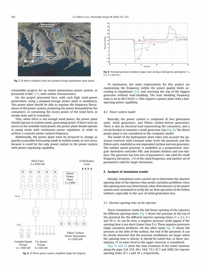
Fig. 7. El Hierro combined wind and pumped-storage hydropower plant layout.
Fig. 9. Penstock pressure evolution (upper zone) during a full injector opening for 1 s,2 s, 5 s and 10 s.
C.A. Platero et al. / Renewable Energy 68 (2014) 515e523520
remarkable projects for an island autonomous power system, aspresented in Ref. [17], with similar characteristics.
For the project presented here, with such high wind-powerpenetration, using a pumped-storage power plant is mandatory.This power plant should be able to regulate the frequency fluctu-ations of the power system, producing the power demanded by theconsumers, or consuming the excess power of the wind farm, insteady-state and in transients.
Thus, when there is not enough wind power, the power plantshould operate in turbine mode, generating power. If there were anexcess in the available wind power, the power plant should operatein pump mode with continuous power regulation, in order toachieve a constant power system frequency.
Additionally, the power plant must be prepared to change asquickly as possible from pumpmode to turbine mode, or vice versa,because it could be the only power station in the power systemwith power-regulating capability.
Fig. 8. El Hierro power system, simplified single line diagram.
To summarize, the main requirements for this project aremaintaining the frequency within the power quality limits ac-cording to regulations [33], and surviving the trip of the biggestgenerator without load-shedding. The load shedding frequencyrelay is set to 48.5 Hz/0.1 s. This requires a power plant with a fast-injecting power capability.
4.2. Power system model
Basically, the power system is composed of two generationunits: wind generators; and Pelton turbine-driven generators.There is also an electrical load representing the consumers, and acircuit breaker to simulate a wind-generator trip (Fig. 6). The dieselpower plant is not considered in the computer model.
The model of the hydropower plant takes into account the up-stream reservoir with constant water level, the penstock, and thePelton units, modelled as one equivalent turbine and one generator.The turbine speed governor is modelled as a proportionaleinte-gralederivative controller PID, and includes limiters and rate lim-iters. The governor has two sets of parameters: one valid for smallfrequency deviation,�1% of the rated frequency; and another set ofparameters valid for larger deviations.
5. Analysis of simulation results
Initially, simulations were carried out to determine the shortestopening time of the injectors that avoids cavitation problems. Oncethis opening timewas determined, other disturbances in the powersystemwere simulated to verify the no-flow operation of the Peltonturbines, especially in the case of wind-generation loss.
5.1. Shortest opening time of the injectors
These simulations study the full linear opening of the injectorsfor different opening times. Fig. 9 shows the pressure at the top ofthe penstock for the different injector-opening times (1 s, 2 s, 5 sand 10 s). As can be seen, a negative pressure could appear if theopening time is too short (lower than 2 s). These negative pressuresimply cavitation problems. On the other hand, Fig. 10 shows thepressure at the inlet of the turbine, the end of the penstock. It canbe clearly observed that the pressure oscillations are larger whenthe opening time is shorter. It should be noted that, in these sim-ulations, 17 m water level in the upper reservoir is considered.
Figs. 11 and 12 show the time evolution of the water hammeralong the pipe (2.8, 17.6, 36.1, 54.6, 73.1, 91.7 and 100%) for injectoropening times of 1 s and 10 s, respectively.

Fig. 10. Penstock pressure evolution (turbine inlet) during a full injector opening for1 s, 2 s, 5 s and 10 s.
Fig. 12. Piezometric head evolution during a full injector opening in 10 s along thepenstock.
C.A. Platero et al. / Renewable Energy 68 (2014) 515e523 521
Theminimum total opening time of the injectors has been set to10 s because it is the shortest time that avoids hydraulic problems,even if the upper reservoir is at its minimum operating level.
5.2. Wind-generator trip
From the power system point of view, the most severe scenariois the tripping of one wind generator at full load, during the min-imum load period. In the simulations, the wind-generator triprepresents a 100% loss of generation in the period of minimum load.
During the initial conditions, the frequency is 50 Hz, while thePelton turbine-driven generator is operating at no flow (z0 MW),so all the loads are supplied by the wind generator (z2.3 MW).
The wind-generator trip is simulated by opening its breaker.Subsequently, the 4 hydro generators increase their generated po-wer to maintain the system frequency. In this case, the fastest po-wer injection to the system is mandatory to avoid thedisconnection of consumers.
However, owing to the hydraulic limitations, the opening timeof the injectors is limited to 10 s. So, it is necessary to add additionalinertia to the generators, in order to keep the frequency above theload-shedding threshold.
Simulations have been performed to determine the minimuminertia of the generators, in order to not fall below certain limits offrequency, and to set the turbine speed governor parameters.
The minimum frequency reached depends on the inertia of thehydro generators (see Table 1), and should be coordinated with theload-shedding relay installed on the island power system. In Fig. 13the frequency oscillations resulting from the wind-generator trip,for different hydro generator inertia, are shown.
Fig. 11. Piezometric head evolution during a full injector opening in 1 s along thepenstock.
In order to get a minimum frequency of 48.8 Hz, an inertia of 6 sis required. Fig. 14 shows the complete frequency evolution after agenerator trip, highlighting the interaction between the hydrauliccircuit dynamics and the power system frequency, as the period ofthe frequency oscillation corresponds to the penstock waterhammer period T ¼ 4L/a ¼ 4.3 s.
Fig. 15 shows the evolution of the main turbine variables after agenerator trip. Although the net head drops slightly (0.1 pu) justafter the injectors open, the flow increases from zero to a positivevalue. So, the mechanical power supplied by the turbines also in-creases from zero to a positive value.
6. Conclusions
A novel operation mode of generators driven by Pelton turbineshas been presented in this paper. This method has been validatedby computer simulations.
The purpose of this no-flow operation mode is to reduce thetime needed to supply power using a hydropower plant. This timereduction is of paramount importance in the case of lack of wind, ora wind-generator trip, in an isolated power system. In this way,wind penetration can be increased, supplying power in a reliableand efficient way. With this aim, it must be taken into account thatan injector’s opening time has a minimum value limited by thehydraulic characteristics of the penstock. In order to overcome theeffect of this limitation, an increase in hydro generator units’ inertiais proposed. In the case study, the minimum inertia that avoidsload-shedding is quantified.
According to the simulations performed, a 100% wind powerpenetration could be reached.
This operation mode will be tested in the electrical grid of asmall island, called El Hierro, in the Canary archipelago, where acombined wind and pumped storage power plant is underconstruction.
To summarize, the no-flow operation main advantages are:
� fastest power injection in the case of requiring the alternativepower system (penstock design limit may be overcome byincreasing hydro generators’ inertia).
Table 1Minimum frequency reached after a wind-generator trip.
Hydro generator inertia [s] Minimum frequency [Hz]
6 48.84.5 48.53 47.75

Fig. 13. Frequency evolution during a wind-generator trip, for different values of thehydro generator inertia coefficient H (6 s, 4.5 s and 3 s).
Fig. 14. Frequency evolution during a wind-generator trip, for a 6 s value of the hydrogenerator inertia coefficient, H, and 4 Pelton generators online.
Table 2Penstock ratings.
Penstock 1
Diameter 1 mLength 2577 mDarcyeWeisbach friction loss coefficient 0.015Wave speed 1193 m/sNumber of elements for simulation 54
Table 3Pelton turbine ratings
Pelton turbines 4
Rated power 2830 kWRated flow 0.5 m3/sGross head 670 mNet head 651 mRated speed 1000 rpmNumber of jets per runner 1Type Horizontal
Table 4Hydro generator ratings
Hydro synchronous generators 4
Rated apparent power 3300 kVARated Power Factor 0.8Rated voltage (�5.0%) 6 kVFrequency 50 HzPairs of poles 3Rated speed 1000 rpmDirect-axis synchronous reactance (unsat) Xd 1.901 puQuadrature-axis synchronous reactance Xq 1.049 puDirect-axis subtransient reactance (unsat) X0d 0.183 puDirect-axis subtransient reactance (unsat) X00d 0.120 puLeakage reactance (stator) Xl 0.125 pu
C.A. Platero et al. / Renewable Energy 68 (2014) 515e523522
� maximum wind-power penetration in the power system.However, additional inertia could be needed to maintain thefrequency while the turbine jet reaches the required flow.
� standard equipment with no special design.
Other advantages related to the increase in the number ofgenerators in operation are:
� the hydropower plant could contribute to the voltage control ofthe grid, providing reactive power if required.
� increase in the reactive current injection during faults.� improvement of the power system transient stability.
In addition to the innovative design, this type of power plantwill allow the more efficient harnessing of wind power.
Fig. 15. Evolution of turbine inlet pressure H, flow Q, valve opening Y and speed N,during a wind-generator trip, for a hydro generator inertia coefficient, H, of 6 s and 4Pelton generators online.
Acknowledgements
The authors wish to thank the technical support of J.R. Diago, M.Alvarez and C. Romero, of ENDESA Generación SA. Also theywish toacknowledge the support of the Intellectual Property Departmentof ENDESA [34], as well as Fundación Caja Madrid for its financialsupport.
Appendix
Direct-axis transient open-circuit time constant T0do 4.354 sDirect-axis transient short-circuit time T0d 41 msDirect-axis subtransient short-circuit time T00d 17 msStator resistance per phase (95 �C) 0.002 puInertia Various s
Table 5Pumps ratings
Pumps 6 2
Rated power 500 1500 kWRated flow 210 640 m3/hGross head 690 690 mMaximum efficiency 78.1 81.9 [%]Rated speed 2965 2973 rpmMotor Asynchronous
fixed speedAsynchronous variable speed
Type High pressurehorizontal
High pressure horizontal

C.A. Platero et al. / Renewable Energy 68 (2014) 515e523 523
References
[1] Kundur P. Power system stability and control. Palo-Alto, California: McGraw-Hill; 1994.
[2] Steinke F, Wolfrum P, Hoffmann C. Grid vs. storage in a 100% renewableEurope. Renew Energy 2013;50:826e32.
[3] De Vos K, Petoussis A, Driesen J, Belmans R. Revision of reserve requirementsfollowing wind power integration in island power systems. Renew Energy2013;50:268e79.
[4] Bergant A, Simpson AR, Tisseling AS. Water hammer with column separation:a historical review. J Fluids Struct 2006;22(2):135e71.
[5] Blonbou R. Very short-term wind power forecasting with neural networks andadaptive Bayesian learning. Renew Energy 2011;36:1118e24.
[6] Xu M, Zhuan X. Optimal planning for wind power capacity in an electric po-wer system. Renew Energy 2013;53:280e6.
[7] Cimuca G, Breban S, Radulescu MM, Saudemont C, Robyns B. Design andcontrol strategies of an induction-machine-based flywheel energy storagesystem associated to a variable-speed wind generator. IEEE Trans EnergyConvers 2007;25:526e34.
[8] Khalid M, Savkin AV. An optimal operation of wind energy storage system forfrequency control based on model predictive control. Renew Energy 2012;48:127e32.
[9] Abbaspour M, Satkin M, Mohammadi-Ivatloo B, Hoseinzadeh Lotfi F,Noorollahi Y. Optimal operation scheduling of wind power integrated withcompressed air energy storage (CAES). Renew Energy 2013;51:53e9.
[10] Valdés R, Lucio JH, Rodríguez LR. Operational simulation of wind power plantsfor electrolytic hydrogen production connected to a distributed electricitygeneration grid. Renew Energy 2013;53:249e57.
[11] Muyeen SM, Takahashi R, Murata T, Tamura J. Integration of an energycapacitor system with a variable-speed wind generator. IEEE Trans EnergyConvers 2006;24:740e9.
[12] Ashourian MH, Cherati SM, Mohd Zin AA, Niknam N, Mokhtar AS, Anwari M.Optimal green energy management for island resorts in Malaysia. RenewEnergy 2013;51:36e45.
[13] Hedegaard K, Meibom P. Wind power impacts and electricity storage e a timescale perspective. Renew Energy 2012;37:318e24.
[14] Katsaprakakisa D Al, Christakis DG, Zervosb A, Papantonis D, Voutsinas S.Pumped storage systems introduction in isolated power production systems.Renew Energy 2008;33:467e90.
[15] Nicolet C, Vaillant Y, Kawkabani B, Allenbach P, Simond J-J, Avellan F. Pumpedstorage units to stabilize mixed islanded power network: a transient analysis.In: Proceedings of HYDRO 2008, October 6-9, 2008, in Ljubljana, Slovenia.Paper 16.1.
[16] Nicolet C, Pannatier Y, Kawkabani B, Schwery A, Avellan F, Simond J-J. Benefitsof variable speed pumped storage units in mixed islanded power networkduring transient operation. In: Proceedings of HYDRO 2009, October 26-28,2009, in Lyon, France. Paper 23.3.
[17] Papaefthymiou SV, Karamanou EG, Papathanassiou SA, Papadopoulos MP.Wind-hydro-pumped storage station leading to high RES penetration in theautonomous island systemof Ikaria. IEEE Trans Sustain Energy 2010;1:163e72.
[18] Papaefthimiou S, Karamanou E, Papathanassiou S, Papadopoulos M. Operatingpolicies for wind-pumped storage hybrid power stations in island grids. IETRenew Power Gener 2009;3(3):293e307.
[19] Kapsalia M, Anagnostopoulosb JS, Kaldellis JK. Wind powered pumped-hydrostorage systems for remote islands: a complete sensitivity analysis based oneconomic perspectives. Appl Energy 2012;99:430e44.
[20] Johnson RM, Chow JH, Dillon MV. Pelton turbine deflector overspeed controlfor a small power system. IEEE Trans Power Syst 2004;19(2):1032e7.
[21] Wylie EB, Streeter VL. Fluid transients in systems. Englewood Cliffs, N.J:Prentice Hall; 1993.
[22] Jaeger RC. Fluid transients in hydro-electric engineering practice. .Glasgow:Blackie; 1977.
[23] Paynter HM. Surge and water hammer problems. Trans ASCE 1953;146:962e1009.
[24] Souza Jr OH, Barbieri N, Santos AHM. Study of hydraulic transients in hy-dropower plants through simulation of nonlinear model of penstock andhydraulic turbine model. IEEE Trans Power Syst 1999;14(4):1269e72.
[25] Nicolet C. Hydroacoustic modelling and numerical simulation of unsteadyoperation of hydroelectric systems. Thesis EPFL n� 3751, http://library.epfl.ch/theses/?nr¼3751; 2007.
[26] Nicolet C, Greiveldinger B, Hérou J-J, Kawkabani B, Allenbach P, Simond J-J,et al. High order modeling of hydraulic power plant in islanded powernetwork. IEEE Trans Power Syst 2007;22(4):1870e81.
[27] Pannatier Y, Kawkabani B, Sari G, Simond J-J. Stability studies of a mixedislanded power network with varspeed units using simplified models of theconverters. Energy Conversion Congress and Exposition (ECCE) IEEE; 2010:2552e7.
[28] Padoan Jr AC, Kawkabani B, Schwery A, Ramirez C, Nicolet C, Simond JJ, et al.Dynamical behavior comparison between variable speed and synchronousmachines with PSS. IEEE Trans Power Syst 2010;25:1555e65.
[29] Red Eléctrica de España S.A. Balance del sistema eléctrico canario 2010. http://www.ree.es/sala_prensa/web/inc/fichero.aspx?ruta¼especiales/archivos&fichero¼pjbwxf5un6ka.pdf.
[30] Red Eléctrica de España S.A. Power demand tracking in real time. http://www.ree.es/seie/canarias/curvas_demanda.asp.
[31] Ministerio de Agricultura Alimentación y Medio Ambiente. El Hierro, en elcamino hacia la autosuficienca energética. www.magrama.gob.es.
[32] Iglesias G, Carballo R. Wave resource in El Hierro e an island towards energyself-sufficiency. Renew Energy 2011;36:689e98.
[33] European Standard EN 50160:2007. Voltage characteristics of electricitysupplied by public distribution networks.
[34] Platero CA, Blazquez F, Rodríguez J, Ballesteros JC, Veganzones C, Martínez S,et al. Control method and system for hydraulic wind farms with pumpedaccumulation. International Patent, PCT/ES2010/070133. March 9, 2010.