Increasing Wanzhou Power Transfer Capability by 550kV ... · PDF fileIncreasing Wanzhou Power...
5
1 Increasing Wanzhou Power Transfer Capability by 550kV Fixed Series Capacitor FSC Fengjie Lutz Kirschner, Quan Bailu, Ding Yansheng, Wang Zuli, Zhou Yan, Karl Uecker Abstract-- In summer of 2005 the Fengjie Series Compensation System located in the Wanzou 500kV ac-network has been ordered and designed for delivery, erection and commissioning. The power demand of the growing chinese industries requires an economical solution for an increase of power transfer capability with the existing lines. Fixed series compensation has been found as the appropriate choice not only to enable the desired power increase but also to stabilize the interconnected networks by reducing the connecting line impedance. Starting of commercial operation of two capacitors located in two serial lines is scheduled for August 2006. This paper will give an overview of the design philosophy of the capacitor system and for the choice of the component rating. Index Terms-- FSC-Fixed Series Capacitor, Fengjie, MOV– Metal Oxide Varistor, Spark Gap, Dynamic Stability, PSCAD/EMTDC I. INTRODUCTION HE Chuanyu Grid-to-Central China Mains project actually consist of two circuits of 500 kV lines, which start in the west from Wanxian 500 kV Substation and extend to the east to Longquan 500 kV HVDC Converter Station. Each circuit has a line length of 360km. Fengjie 500 kV Series Capacitor Station is located about 130km away from Wanxian substation of the above two circuits, with the site at Fengjie County, Wanzhou District, Chongqing City (Fig. 1). Due to the demanding power increase the implantation of transmission reinforcements in Wanzhou area is foreseen. Fengjie 500kV Series Compensation Station is an important station for Chuanyu Grid-to-Central China Mains Interconnection Project planned by the State Grid Corporation of China. It has a capacity of 2×610 MVar and compensation level of 35% and its compensation equipment will be of Fixed Series Capacitor type (FSC) protected by metal oxide varistors and spark gaps. Lutz Kirschner, MIEEE, is with SIEMENS, Department. PTD H166, 91050 Erlangen, PO Box 3220, Freyeslebenstr. 1, Germany (e-mail: [email protected]). Quan Bailu, (???), is with CSEPDI-Chinese South-East Power Design Institute, (your address), (e-mail: [email protected]). Ding Yancheng (address), (e-mail: ???). Wang Zuli (address), (e-mail: ???). Zhou Yan (address), (e-mail: ???). Karl Uecker is with SIEMENS, Department. PTD H16M, 91050 Erlangen, PO Box 3220, Freyeslebenstr. 1, Germany (e-mail: [email protected]). Commercial operation is planned for summer 2006. The ac-network at Wanxian is coupled through this corridor to the Three Gorges HVDC converter station in Longquan by two parallel lines with connections in Fengjie substation (Fig. 2). Fig. 1. Location of FSC Fengjie (China) HVDC Wanxian 500kV Longquan Converter Station 500kV Fengjie 35kV 220kV Neutral point grounded directly 220kV 35kV Neutral point grounded directly 140km 220km 140km 220km Fengjie Fig. 2. Electrical Equivalent for FSC Fengjie ac-network The FSC system consists of two capacitors, one in each of the parallell lines located in Fengjie substation entering from Wanxian and Longquan. Both have an identical design and have identical impedances at the same compensation degree of 35%. In the following the data for one of both will be given being valid for the other one as well. The most economical design has been found for a gap protected MOV scheme with an MOV total energy capability of 35MJ per phase. External faults are covered by the installed metal oxide varistors (MOV) without bypassing the capacitor. In case of internal faults, the capacitor is immediately bypassed by the gap and temporarily locked out by a switch. Future ac system configurations have been investigated during the final design to find the necessary energy requirements of T
-
Upload
nguyendang -
Category
Documents
-
view
217 -
download
2
Transcript of Increasing Wanzhou Power Transfer Capability by 550kV ... · PDF fileIncreasing Wanzhou Power...
1
Increasing Wanzhou Power Transfer Capability by 550kV Fixed Series Capacitor FSC Fengjie
Lutz Kirschner, Quan Bailu, Ding Yansheng, Wang Zuli, Zhou Yan, Karl Uecker
Abstract-- In summer of 2005 the Fengjie Series Compensation
System located in the Wanzou 500kV ac-network has been ordered and designed for delivery, erection and commissioning. The power demand of the growing chinese industries requires an economical solution for an increase of power transfer capability with the existing lines. Fixed series compensation has been found as the appropriate choice not only to enable the desired power increase but also to stabilize the interconnected networks by reducing the connecting line impedance. Starting of commercial operation of two capacitors located in two serial lines is scheduled for August 2006. This paper will give an overview of the design philosophy of the capacitor system and for the choice of the component rating.
Index Terms-- FSC-Fixed Series Capacitor, Fengjie, MOV–Metal Oxide Varistor, Spark Gap, Dynamic Stability, PSCAD/EMTDC
I. INTRODUCTION HE Chuanyu Grid-to-Central China Mains project
actually consist of two circuits of 500 kV lines, which start in the west from Wanxian 500 kV Substation and extend to the east to Longquan 500 kV HVDC Converter Station. Each circuit has a line length of 360km. Fengjie 500 kV Series Capacitor Station is located about 130km away from Wanxian substation of the above two circuits, with the site at Fengjie County, Wanzhou District, Chongqing City (Fig. 1). Due to the demanding power increase the implantation of transmission reinforcements in Wanzhou area is foreseen. Fengjie 500kV Series Compensation Station is an important station for Chuanyu Grid-to-Central China Mains Interconnection Project planned by the State Grid Corporation of China. It has a capacity of 2×610 MVar and compensation level of 35% and its compensation equipment will be of Fixed Series Capacitor type (FSC) protected by metal oxide varistors and spark gaps.
Lutz Kirschner, MIEEE, is with SIEMENS, Department. PTD H166, 91050 Erlangen, PO Box 3220, Freyeslebenstr. 1, Germany (e-mail: [email protected]).
Quan Bailu, (???), is with CSEPDI-Chinese South-East Power Design Institute, (your address), (e-mail: [email protected]).
Ding Yancheng (address), (e-mail: ???). Wang Zuli (address), (e-mail: ???). Zhou Yan (address), (e-mail: ???). Karl Uecker is with SIEMENS, Department. PTD H16M, 91050 Erlangen,
PO Box 3220, Freyeslebenstr. 1, Germany (e-mail: [email protected]).
Commercial operation is planned for summer 2006. The ac-network at Wanxian is coupled through this corridor to the Three Gorges HVDC converter station in Longquan by two parallel lines with connections in Fengjie substation (Fig. 2).
Fig. 1. Location of FSC Fengjie (China)
HVDC
Wanxian500kV
LongquanConverter Station 500kVFengjie
35kV
220kV
Neutral point grounded directly
220kV
35kV
Neutral point grounded directly
140km 220km
140km 220km
Fengjie
Fig. 2. Electrical Equivalent for FSC Fengjie ac-network
The FSC system consists of two capacitors, one in each of the parallell lines located in Fengjie substation entering from Wanxian and Longquan. Both have an identical design and have identical impedances at the same compensation degree of 35%. In the following the data for one of both will be given being valid for the other one as well. The most economical design has been found for a gap protected MOV scheme with an MOV total energy capability of 35MJ per phase. External faults are covered by the installed metal oxide varistors (MOV) without bypassing the capacitor. In case of internal faults, the capacitor is immediately bypassed by the gap and temporarily locked out by a switch. Future ac system configurations have been investigated during the final design to find the necessary energy requirements of
T
e0103302
Rectangle
2
the MOV. The calculations are based on a PSCAD/EMTDC model of the ac-system corridor with both different actual and future ac-system configuration stages including the detailed representation of the capacitors and their control and protection features.
II. SINGLE LINE AND MAIN DATA The fault calculation is the basis for the type of protection
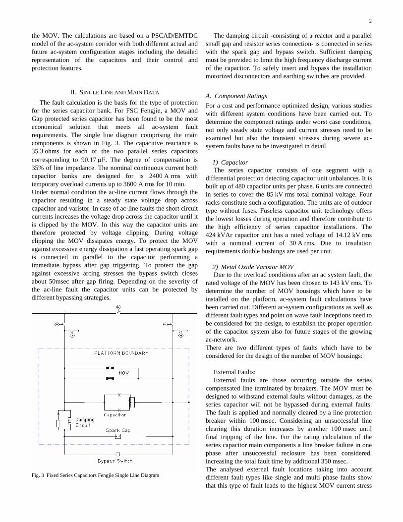
for the series capacitor bank. For FSC Fengjie, a MOV and Gap protected series capacitor has been found to be the most economical solution that meets all ac-system fault requirements. The single line diagram comprising the main components is shown in Fig. 3. The capacitive reactance is 35.3 ohms for each of the two parallel series capacitors corresponding to 90.17 µF. The degree of compensation is 35% of line impedance. The nominal continuous current both capacitor banks are designed for is 2400 A rms with temporary overload currents up to 3600 A rms for 10 min. Under normal condition the ac-line current flows through the capacitor resulting in a steady state voltage drop across capacitor and varistor. In case of ac-line faults the short circuit currents increases the voltage drop across the capacitor until it is clipped by the MOV. In this way the capacitor units are therefore protected by voltage clipping. During voltage clipping the MOV dissipates energy. To protect the MOV against excessive energy dissipation a fast operating spark gap is connected in parallel to the capacitor performing a immediate bypass after gap triggering. To protect the gap against excessive arcing stresses the bypass switch closes about 50msec after gap firing. Depending on the severity of the ac-line fault the capacitor units can be protected by different bypassing strategies.
Fig. 3 Fixed Series Capacitors Fengjie Single Line Diagram
The damping circuit -consisting of a reactor and a parallel small gap and resistor series connection- is connected in series with the spark gap and bypass switch. Sufficient damping must be provided to limit the high frequency discharge current of the capacitor. To safely insert and bypass the installation motorized disconnectors and earthing switches are provided.
A. Component Ratings For a cost and performance optimized design, various studies with different system conditions have been carried out. To determine the component ratings under worst case conditions, not only steady state voltage and current stresses need to be examined but also the transient stresses during severe ac-system faults have to be investigated in detail. 1) Capacitor
The series capacitor consists of one segment with a differential protection detecting capacitor unit unbalances. It is built up of 480 capacitor units per phase. 6 units are connected in series to cover the 85 kV rms total nominal voltage. Four racks constitute such a configuration. The units are of outdoor type without fuses. Fuseless capacitor unit technology offers the lowest losses during operation and therefore contribute to the high efficiency of series capacitor installations. The 424 kVAr capacitor unit has a rated voltage of 14.12 kV rms with a nominal current of 30 A rms. Due to insulation requirements double bushings are used per unit. 2) Metal Oxide Varistor MOV
Due to the overload conditions after an ac system fault, the rated voltage of the MOV has been chosen to 143 kV rms. To determine the number of MOV housings which have to be installed on the platform, ac-system fault calculations have been carried out. Different ac-system configurations as well as different fault types and point on wave fault inceptions need to be considered for the design, to establish the proper operation of the capacitor system also for future stages of the growing ac-network. There are two different types of faults which have to be considered for the design of the number of MOV housings:
External Faults: External faults are those occurring outside the series
compensated line terminated by breakers. The MOV must be designed to withstand external faults without damages, as the series capacitor will not be bypassed during external faults. The fault is applied and normally cleared by a line protection breaker within 100 msec. Considering an unsuccessful line clearing this duration increases by another 100 msec until final tripping of the line. For the rating calculation of the series capacitor main components a line breaker failure in one phase after unsuccessful reclosure has been considered, increasing the total fault time by additional 350 msec. The analysed external fault locations taking into account different fault types like single and multi phase faults show that this type of fault leads to the highest MOV current stress
3
without any allowed bypassing action. According to this simulations a MOV current of 8 kA has been stated for the protection system parameter to detect internal faults.
Fig. 4. MOV bank on a platform
Internal Faults: Internal faults are those occurring within the series
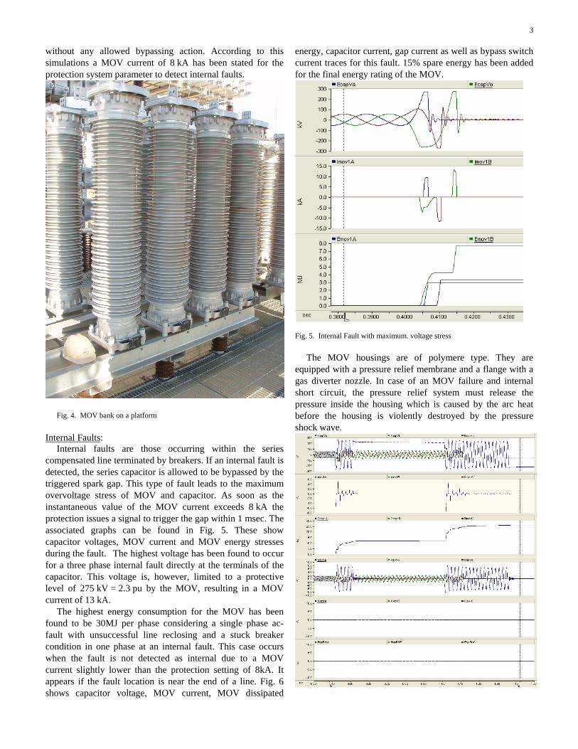
compensated line terminated by breakers. If an internal fault is detected, the series capacitor is allowed to be bypassed by the triggered spark gap. This type of fault leads to the maximum overvoltage stress of MOV and capacitor. As soon as the instantaneous value of the MOV current exceeds 8 kA the protection issues a signal to trigger the gap within 1 msec. The associated graphs can be found in Fig. 5. These show capacitor voltages, MOV current and MOV energy stresses during the fault. The highest voltage has been found to occur for a three phase internal fault directly at the terminals of the capacitor. This voltage is, however, limited to a protective level of 275 kV = 2.3 pu by the MOV, resulting in a MOV current of 13 kA.
The highest energy consumption for the MOV has been found to be 30MJ per phase considering a single phase ac-fault with unsuccessful line reclosing and a stuck breaker condition in one phase at an internal fault. This case occurs when the fault is not detected as internal due to a MOV current slightly lower than the protection setting of 8kA. It appears if the fault location is near the end of a line. Fig. 6 shows capacitor voltage, MOV current, MOV dissipated
energy, capacitor current, gap current as well as bypass switch current traces for this fault. 15% spare energy has been added for the final energy rating of the MOV.
Fig. 5. Internal Fault with maximum. voltage stress The MOV housings are of polymere type. They are
equipped with a pressure relief membrane and a flange with a gas diverter nozzle. In case of an MOV failure and internal short circuit, the pressure relief system must release the pressure inside the housing which is caused by the arc heat before the housing is violently destroyed by the pressure shock wave.

4
Fig. 6. MOV Energy Rating due to not detected Internal Fault 3) Spark Gap
The spark gap has to protect the MOV against overload in case of internal faults. The protection fires the gap within 1 msec as soon as a threshold value of 8 kA is exceeded. It is absolutely necessary that the gap bypasses the MOV as soon as possible because of the high rate of rise energy dissipation in MOV during internal faults. The gap consists of two housings installed on top of each other. The main trigger circuit is located in the lower housing while the upper one is passive. It fires successively after the lower gap has been triggered.
Fig. 7. Spark Gap flashover during high current short circuit type test The flashover voltage can be adjusted from 248 to 303 kV peak. The thermal fault current carrying capability is 40 kA rms. To avoid excessive arcing the spark-gap is always triggered in conjunction with a closing impulse to the bypass switch. Therefore the arcing stresses only occur for about 50 msec on the gap electrodes. Closing the bypass switch will extinguish the arc immediately.
4) Damping Circuit
The damping circuit is designed to discharge the capacitor in case of an internal fault when the voltage across the capacitor reaches the protective level. For both capacitors the same components and their ratings are chosen. It is located in series to the spark gap and bypass switch and is therefore stressed by line current only in case of bypass. To limit the peak current value of the discharging capacitor, a reactor of 600 µH has been chosen for both series capacitors. This results in a discharge frequency of about 684 Hz. The appropriate damping is achieved by a resistor of 6 ohms located in parallel to the damping reactor. The discharge characteristic can be found in Fig. 9, where capacitor voltage, current and dissipated energy in the damping resistor is given.. To avoid a steady state current drain in the resistor, a small spark gap is also included in series with the resistor: The small gap fires for voltages exceeding the overload requirements of the capacitor. Therefore the resistor need not be rated for steady state conditions. The impulse energy rating of the resistor is sufficient for a duty cycle of two consecutive discharges.
Fig. 8. Inside view into the damping reactor
5) Bypass Switch
The 550kV SF6-bypass switch is designed as three single-phase units, one for each phase with a rated voltage of 245kV across the open switch coils and a closing time of 50 ms. It consists of porcelain insulator columns with a hydraulic opening mechanism. The switch is used for insertion and disconnection of the bank. In case of internal faults, it also closes so the spark gap current commutates to the switch releasing the gap from further current stress. Initiated by the protection system it also closes if the rated MOV energy is exceeded. Due to this requirements the switch is designed for high frequency capacitor discharges as well as power frequency currents and dynamic short circuit currents up to a thermal limit of 50 kA rms.

5
Fig. 9. Capacitor Discharge of FSC Fengjie
III. LAYOUT CONSIDERATIONS The SC components are installed on a platform which is
connected to the high potential of the ac-transmission line. This design leads to the lowest creepage distances and flashover voltages across the components. The platform itself is built up on reinforced structures of porcelain insulators to provide an appropriate line to earth creepage distance with a height of approximately 6 meters. The capacitor is built up in four racks in an differential protection scheme to detect capacitor unit unbalances. The damping circuit resistor is located within the damping reactor coil. The two spark gap housings are installed on top of each other to save platform space. The MOV housings including the spares per phase are built up in two stacks. The bypass switch is not installed on the platform but located beneath the platform on the ground. Due to the optimized design the platform size is only 15m x 8m and has a total weight of about 40 tons. Fig. 10 shows the platform layout and associated bypass switch for one phase.
IV. CONCLUSION 550kV Fengjie series capacitor project consists of two
series capacitor installations connected in parallel on two parallel lines entering Fengjie substation. The design of the components has been carried out by intensive studies to find an optimized solution for power transfer increase and stabilization of the existing network. The details of the component design are discussed in this paper. The layout as well as the single line diagram is object of discussion. With a
nominal power rating of 610 MVA the Fengjie series capacitors will provide stable and increased power transfer in the Wanzhou 550kV ac system area.
Fig. 10. Layout Drawing of FSC Fengjie
V. REFERENCES [1] Anderson, Farmer – Series Compensation of Power Systems; ISBN 1-
888747-01-3, 1996
[2] Kirschner, Baoshu, Gong, Breuer - Design Aspects of the Chinese 500kV Thyristor Controlled Series Compensation Scheme TCSC Tian Guang, DRPT Conference April 2004, Hongkong
[3] Bohn, Kirschner, Kuhn – TPSC: Thyristor Protected Series Compensator: Design and Control Concepts, CIGRE-XERLAC Conference May 2003, Iguazu Argentina
VI. BIOGRAPHY
Lutz Kirschner, Senior Project Engineer, MIEEE, received his Diploma in Electrical Engineering 1992 from the university of Aachen, Germany. He joined SIEMENS company in the HVDC Department as a system design engineer. He was involved with technical and commercial design of HVDC converter stations. Since 1995 he is responsible for Fixed and Thyristor Controlled Series Capacitor design and was busy in several series capacitor projects worldwide carrying out the basic design studies. He is working on the design of Thyristor Protected Series Capacitor systems (TPSC) and FACTS devices. In the FSC Fengjie project he carried out the Final Basic Design Studies comprising the transient fault calculation and main component ratings. His special fields are time domain digital simulations and system studies. Since 1998 he is a member of IEEE.
Quan Bailu was born (short Bio needed) Ding Yansheng (short Bio needed)
e0103302
Rectangle