Increasing nanohardness and reducing friction of nitride …pugno/NP_PDF/117-TI09.pdf · ·...
7
Increasing nanohardness and reducing friction of nitride steel by laser surface texturing $ E. Gualtieri a,b, , A. Borghi a , L. Calabri a , N. Pugno c , S. Valeri a,b a CNR-INFM-National Research Centre on NanoStructures and BioSystems at Surfaces (S 3 ), via Campi 213/a, 41100 Modena, Italy b Department of Physics, Universita ` degli Studi di Modena e Reggio Emilia, via Campi 213/a, 41100 Modena, Italy c Department of Structural Engineering, Politecnico di Torino, Corso Duca degli Abruzzi 24,10129 Torino, Italy article info Article history: Received 30 August 2007 Received in revised form 25 August 2008 Accepted 23 September 2008 Available online 10 October 2008 Keywords: Surface texture Friction measurement Nanoindentation Atomic force microscope abstract Laser surface texturing is often employed to improve tribological performances of mating surfaces. The principal aim of the present work is to study local modifications induced by laser beam during the texturing process (microdimpling), on the mechanical properties of a 30NiCrMo12 nitride steel. A brief tribological characterization was initially made in order to verify the improvement of tribological behaviour ensured by microdimpling. Friction measurements were carried out in lubricated flat-on-flat and round-on-flat configurations. A sub-surface characterization was performed by focused ion beam cross-section and imaging. Modified material layers were discovered in correspondence of laser-affected zones around dimples, where grain dimensions were observed to be reduced. To quantify this phenomenon, a new theoretical energetic model was developed. Hardness measurements were performed by atomic force microscope nanoindentation. This approach allowed to observe an hardening effect moving from bulk material to dimple edges. Therefore, the theoretical model was integrated with the Hall–Petch’s law in order to quantify the observed hardening behaviour. & 2008 Elsevier Ltd. All rights reserved. 1. Introduction Steels are representative structural materials for almost all kinds of mechanical applications because of their high strength and toughness, good machinability and low cost. Surface hardness and composition play a dominant role against wear under sliding conditions. The efficiency, reliability, and durability of mating mechanical components depend on friction occurring at the interface during the sliding. In addition, the increase in load capacity and power density of engine elements leads to higher intensities of surface interactions. Both the need to reduce friction and the desire to increase power require effective lubrication strategy for sliding surfaces [1]. It has been demonstrated that the presence of artificially created microfeatures can significantly affect tribological beha- viour of lubricated surfaces: specific textures may trap wear particles and reduce ploughing and friction of surfaces, thus increasing the lifetime of the sliding contacts [2–4]. Indeed, when irregularities cover the surface with a sufficient density, they can improve the oil wetting of the surface and thereby facilitate the lubricating film formation promoting its retention between mating surfaces. At higher sliding speed, and with a sufficient supply of oil, individual surface cavities, or grooves, may act as hydrodynamic pressure pockets, reducing friction [5–7]. Various manufacturing methods are utilized to produce textures on contact surfaces (mechanical and lithographical methods, coat- ings and energy beam techniques [8]). Among these, laser surface texturing (LST) offers promising features: extremely fast proces- sing time, clean to the environment and excellent control of the aspect-ratio of the micro-holes [9–11]. By controlling the orienta- tion of the laser beam, and tuning the characteristics of the spot it is possible to easily texture a wide range of material, with no need of vacuum. This technique allows covering samples by regular arrays of ablated dimples, with different size and shape (typically spherical or cylindrical). Several classes of tribological experiments were developed in order to investigate the benefits of LST in terms of transition between different lubrication regimes, reduction of friction coefficients and reduction of wear rates, mainly on steel surfaces [2–4,7–12]. However, the present work intends to face also another specific aspect of this topic. As a matter of fact, there is ARTICLE IN PRESS Contents lists available at ScienceDirect journal homepage: www.elsevier.com/locate/triboint Tribology International 0301-679X/$ - see front matter & 2008 Elsevier Ltd. All rights reserved. doi:10.1016/j.triboint.2008.09.008 $ Presented at the 34th Leeds-Lyon Symposium on Tribology, Lyon, 4th to 7th September 2007. Corresponding author at: Department of Physics, Universita ` degli Studi di Modena e Reggio Emilia, via Campi 213/a, 41100 Modena, Italy. Tel.: +39 0592055741; fax: +39 059 2055235. E-mail address: [email protected] (E. Gualtieri). Tribology International 42 (2009) 699–705
Transcript of Increasing nanohardness and reducing friction of nitride …pugno/NP_PDF/117-TI09.pdf · ·...
ARTICLE IN PRESS
Tribology International 42 (2009) 699–705
Contents lists available at ScienceDirect
Tribology International
0301-67
doi:10.1
$ Pre
Septem� Corr
Modena
Tel.: +3
E-m
journal homepage: www.elsevier.com/locate/triboint
Increasing nanohardness and reducing friction of nitride steel bylaser surface texturing$
E. Gualtieri a,b,�, A. Borghi a, L. Calabri a, N. Pugno c, S. Valeri a,b
a CNR-INFM-National Research Centre on NanoStructures and BioSystems at Surfaces (S3), via Campi 213/a, 41100 Modena, Italyb Department of Physics, Universita degli Studi di Modena e Reggio Emilia, via Campi 213/a, 41100 Modena, Italyc Department of Structural Engineering, Politecnico di Torino, Corso Duca degli Abruzzi 24, 10129 Torino, Italy
a r t i c l e i n f o
Article history:
Received 30 August 2007
Received in revised form
25 August 2008
Accepted 23 September 2008Available online 10 October 2008
Keywords:
Surface texture
Friction measurement
Nanoindentation
Atomic force microscope
9X/$ - see front matter & 2008 Elsevier Ltd. A
016/j.triboint.2008.09.008
sented at the 34th Leeds-Lyon Symposium o
ber 2007.
esponding author at: Department of Physi
e Reggio Emilia, via Campi 213/a, 41100 Mo
9 059 2055741; fax: +39 059 2055235.
ail address: [email protected] (E. Gualtier
a b s t r a c t
Laser surface texturing is often employed to improve tribological performances of mating surfaces. The
principal aim of the present work is to study local modifications induced by laser beam during the
texturing process (microdimpling), on the mechanical properties of a 30NiCrMo12 nitride steel.
A brief tribological characterization was initially made in order to verify the improvement of
tribological behaviour ensured by microdimpling. Friction measurements were carried out in lubricated
flat-on-flat and round-on-flat configurations.
A sub-surface characterization was performed by focused ion beam cross-section and imaging.
Modified material layers were discovered in correspondence of laser-affected zones around dimples,
where grain dimensions were observed to be reduced. To quantify this phenomenon, a new theoretical
energetic model was developed.
Hardness measurements were performed by atomic force microscope nanoindentation. This
approach allowed to observe an hardening effect moving from bulk material to dimple edges.
Therefore, the theoretical model was integrated with the Hall–Petch’s law in order to quantify the
observed hardening behaviour.
& 2008 Elsevier Ltd. All rights reserved.
1. Introduction
Steels are representative structural materials for almost allkinds of mechanical applications because of their high strengthand toughness, good machinability and low cost. Surface hardnessand composition play a dominant role against wear under slidingconditions. The efficiency, reliability, and durability of matingmechanical components depend on friction occurring at theinterface during the sliding. In addition, the increase in loadcapacity and power density of engine elements leads to higherintensities of surface interactions. Both the need to reduce frictionand the desire to increase power require effective lubricationstrategy for sliding surfaces [1].
It has been demonstrated that the presence of artificiallycreated microfeatures can significantly affect tribological beha-viour of lubricated surfaces: specific textures may trap wearparticles and reduce ploughing and friction of surfaces, thus
ll rights reserved.
n Tribology, Lyon, 4th to 7th
cs, Universita degli Studi di
dena, Italy.
i).
increasing the lifetime of the sliding contacts [2–4]. Indeed, whenirregularities cover the surface with a sufficient density, they canimprove the oil wetting of the surface and thereby facilitate thelubricating film formation promoting its retention betweenmating surfaces. At higher sliding speed, and with a sufficientsupply of oil, individual surface cavities, or grooves, may act ashydrodynamic pressure pockets, reducing friction [5–7]. Variousmanufacturing methods are utilized to produce textures oncontact surfaces (mechanical and lithographical methods, coat-ings and energy beam techniques [8]). Among these, laser surfacetexturing (LST) offers promising features: extremely fast proces-sing time, clean to the environment and excellent control of theaspect-ratio of the micro-holes [9–11]. By controlling the orienta-tion of the laser beam, and tuning the characteristics of the spot itis possible to easily texture a wide range of material, with no needof vacuum. This technique allows covering samples by regulararrays of ablated dimples, with different size and shape (typicallyspherical or cylindrical).
Several classes of tribological experiments were developed inorder to investigate the benefits of LST in terms of transitionbetween different lubrication regimes, reduction of frictioncoefficients and reduction of wear rates, mainly on steel surfaces[2–4,7–12]. However, the present work intends to face alsoanother specific aspect of this topic. As a matter of fact, there is
ARTICLE IN PRESS
E. Gualtieri et al. / Tribology International 42 (2009) 699–705700
a lack of information about the possible ‘‘additional effects’’ of theLST process as a consequence of the interaction between laserbeam and material structure. Ablation of surface is accompaniedto local annealing, which could activate phase transitions incorrespondence of the laser-affected zone: laser beam interactionplays a key role in heat propagation, which could result in theformation of modified material layers. Laser heating causesseveral phenomena, in particular on steel surfaces: variations indislocations and residual stresses distributions, formation ofdifferent carbide types, size and shape modification of austeniticgrains and hardening effects [13–15].
The core of the present work is focused on the investigation oflaser–steel interaction in terms of morphological and structuralsub-surface modifications on laser textured nitride steels.30NiCrMo12 nitride steel has been studied. This material (bulkcomposition: 3.00%Ni, 0.80Cr, 0.45Mo, 0.3C, all in wt%) isemployed for automotive application due to its surface strengthguaranteed by hot nitriding treatment. Focused ion beam (FIB)was utilized to explore local properties: thanks to its versatilityand ability to remove and observe trenches of surface withoutintroducing relevant additional damage, this approach is adoptedto characterize sub-surface micro-cracking, defects distributionsand grain structure of material surfaces [16–18]. Sub-surfacemicro-hardness measurements were also performed by indentinga cross-section of the specimen material by using atomic forcemicroscope (AFM) working in nanoindentation mode. Thanks toits ability of simultaneous high resolution indenting and imaging,this powerful tool allows the investigation of the hardnessdistribution in sub-micrometric areas [19,20].
Fig. 1. SEM images of 30NiCrMo12 nitride steel textured surface: (a) 451 tilted top
view and (b) perpendicular cross-section of a singular sectioned dimple: the shape
could be approximated as hemi-spherical.
2. Experimental details
Samples were prepared as discs 26 mm in diameter and 8 mmthick. The discs were first lapped to obtain a surface roughness(Ra) of 0.05mm, then textured by LST. Table 1 contains adescription of the principal parameters of the laser apparatusadopted for the treatment. Textured nitride steel discs showregular arrays of circular dimples with a diameter of 100mm, adepth of 50mm and a surface density of 40% (Fig. 1).
Friction tests were performed using a UMT-2 tribometer(provided by CETRs). During the tests, a constant normal loadwas applied on the samples, which slid at different linear speedsranging between 0.06 and 40 cm s�1 (corresponding to an angularvelocity which ranges between 0.3 and 200 rpm). Frictioncoefficient evolution was recorded in a ‘‘full lubrication’’ config-uration, with the mating counterparts full immerged in a bath of acommercial oil (Vanguards ST-46). Both untextured and texturedsteels were tested for comparison.
Morphological characterization was performed using a dualbeam system (FEIs StrataTM DB235), combining a high-resolu-tion FIB column equipped with a Ga liquid metal ion source (LMIS)and a SEM column equipped with a Schottky field emission gun(SFEG) electron source. Perpendicular ‘‘micro-cross-sections’’ ofsteel surfaces (textured and untextured) were obtained using FIB(Ebeam ¼ 30 KeV) as micro-machining miller, setting 5 nA as ion
Table 1Details of the laser apparatus utilized to produce LST microdimples
Laser type ‘‘Spectron’’ Nd:YAG
Laser beam wavelength 1.06mm
Pulses duration 30 ns
Laser beam energy per pulsation 4 mJ
Laser scanning was carried out by CNC X–Y table under special program providing
definite pore position.
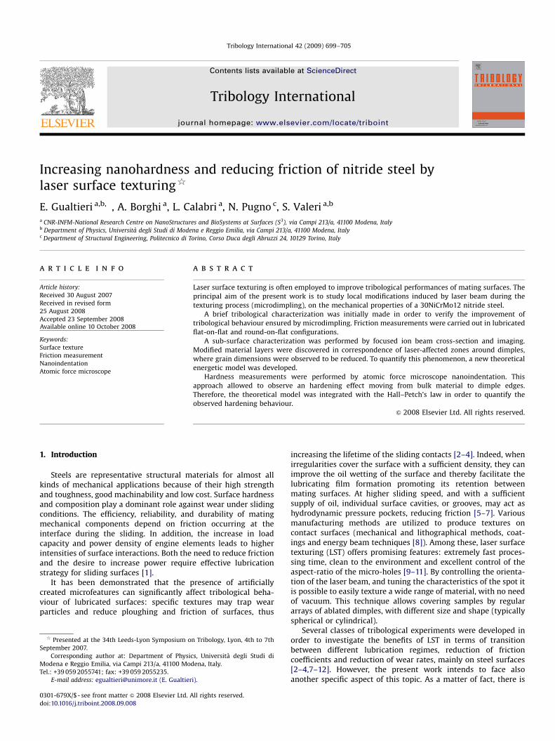
beam current for first rough trench, and 1 nA for final polishing.Sub-surface discovered wall is one side of the perpendiculartrench, milled by progressive steps (Fig. 2). In order to prevent thetopmost material from mechanical intermixing upon contact withenergetic ions [16], the surface sample was protected by a thinplatinum layer (1mm thickness). A Pt-shield had been grownstarting from a gas precursor, and using a 10 pA ion beam currentthat assisted local deposition. Furthermore, by tilting the sampleholder, images of discovered walls were obtained collectingsecondary electrons generated by FIB as primary beam at lowcurrent (50 pA), in order to take advantage of ion-channellingcontrast, which is very useful for grain size analysis [21].
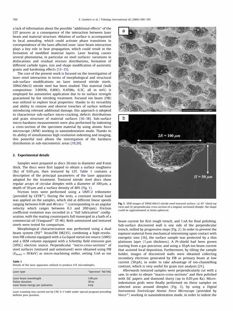
Afterwards textured samples were perpendicularly cut with asaw, in order to obtain ‘‘macro-cross-sections’’ and then polishedwith SiC papers and diamond slurry (up to 0.05mm Ra). Micro-indentation grids were finally performed on these samples onselected areas around dimples (Fig. 3), by using a Digital
Instruments EnviroScope Atomic Force Microscope (provided byVeecos) working in nanoindentation mode, in order to indent the
ARTICLE IN PRESS
Fig. 2. Simplified sketch which summarizes the experimental procedures followed
in order to carry out a morphological sub-surface characterization. SEM image (a)
shows the thin Pt-shield grown in-situ, beside a dimple edge, by a FIB-assisted
deposition. Dotted lines represent the projection of the trench, successfully milled
by FIB setting high ion current mode. Thus, a ‘‘micro-cross-section’’ was gained by
progressive rastering steps: white arrow indicates the relative depth profile (b).
Sub-surface discovered wall was imaged using FIB as primary probe (low current
mode), by tilting the sample holder.
Fig. 3. Simplified sketch which summarizes the experimental procedures followed
in order to carry out a mechanical sub-surface characterization of ‘‘macro-cross-
sectioned’’ textured steel samples. A micro-indentation grid was realized, and
successfully imaged by AFM on selected areas around dimple edges. Spacing
between two adjacent indentations (aE1mm) is maintained constant, but could
slightly change in proximity of the border, in order to faithfully follow the shape of
the dimple edge.
E. Gualtieri et al. / Tribology International 42 (2009) 699–705 701
sample and image it right after the indentation. All the indenta-tions were performed by a Berkovich diamond tip mounted on asapphire cantilever (the whole probe had been assembled andprovided by Micro Star Technologiess) under the same conditions;in particular the load applied on the sample was 1.5 V in terms ofphotodetector voltage. Thus, considering the cantilever stiffness(5085 N m�1) and the deflection sensitivity (130 V nm�1), amaximum indentation load of about 992mN was estimated.Further details on this setup are reported in [20]. Finally, theindented area was imaged using a standard AFM tapping probe(MPP-11100-Tap300 Metrology Probes by Veecos) in order tomeasure the projected contact area in a direct way and thusevaluate the hardness just dividing the maximum load by thisarea. This approach allows to solve the pile-up problem, whichaffects the results in the Oliver–Pharr method [22–24]. The O–Papproach guarantees hardness measurement without imaging theindentation impression, since it establishes a relationshipbetween the projected area of the indentation impression, themaximum depth of indentation (hmax) and the initial unloadingstiffness (S), where hmax and S are both measurable from theload–displacement curve. However, the Oliver–Pharr methodquite overestimates the hardness values when the pile-up effectis not negligible, such in this case. With AFM nanoindentation,since it is possible to measure directly the contact area, we areable to take into account the actual presence of pile-up [20].
3. Results and discussion
3.1. Friction measurements
The experimental analysis was carried out comparing theperformances of textured and untextured surfaces under the sametribological conditions, repeating each individual test in order toverify the reproducibility of the results.
Average values of friction coefficients (considering standarddeviations as error bars) were summarized in the form of aStribeck curve (Fig. 4a), obtained showing the friction coefficientas a function of Stribeck parameter, calculated as the ratiobetween v (linear speed) and W (nominal contact pressure) andassuming the lubricant viscosity (Z) as constant. In the casereported in Fig. 4a the pin-on-disk mode was exploited. Conformalcontact was obtained by using a smooth stainless steel pin asstatic counterpart with a round contact area of 5.5 mm indiameter. Thus, the nominal flat-on-flat contact pressure wasroughly 0.2 MPa. Different ranges of mating speeds were exploredapplying a constant normal load (4.5 N), thus ranging the Stribeckparameter roughly between 0.3 and 200 cm s�1 MPa�1.
During the whole experimental analysis, both systems (tex-tured and untextured) operated in hydrodynamic lubricationregime because of the massive presence of lubricant, even whenthe tribological conditions became more severe (low speeds andStribeck parameter lower than 10 cm s�1 MPa�1). The trend of thecurves reported in Fig. 4a (roughly constant) shows no significanttransition towards boundary or mixed lubrication regimes.Nevertheless, the textured surface exhibits considerable lowerfriction coefficient than untextured surface. The reason isascribable to the higher hydrodynamic lift ensured by the dimplesregularly distributed on the contact area, thus capable to behaveas integrated pressure pockets.
Subsequently an endurance test was performed on bothtextured and untextured discs. In this case the tribometer wasconfigured in ball-on-disk mode: static counterpart was astainless steel ball (diameter: 4 mm), and the test was carriedout applying a normal load of 4 N (the nominal contact pressurereaches about 1 GPa estimating by Hertzian model). Mating

ARTICLE IN PRESS
0.160.150.140.130.120.110.100.090.080.070.060.050.040.030.020.010.00
Fric
tion
coef
ficie
nt
1 10 100
Stribeck parameter (cm s-1 MPa-1)
STRIBECK CURVEtextured surfaceuntextured surface
0.12
0.10
0.08
0.06
0.04
0.02
0.00
Fric
tion
coef
ficie
nt
1.41.21.00.80.60.40.20.0
ENDURANCE TESTtextured surfaceuntextured surface
Laps (x 105)
Fig. 4. (a) Stribeck curves: friction coefficients against Stribeck parameters
calculated as the ratio between mating speeds (ranging from 0.06 to 40 cm s�1)
and nominal contact pressures (maintained constant: roughly 0.2 MPa). (b)
Endurance test: comparison of the evolution of the friction coefficients (plotted
as a function of the number of laps ) relative to untextured case (continuous line)
and textured case (dotted line).
Fig. 5. FIB images obtained by tilting samples after sub-surface FIB micro-trenches
milled on (a) untextured and (b) textured 30NiCrMo12 nitride steel. Dimple edge is
visible on the top corner of (b).
E. Gualtieri et al. / Tribology International 42 (2009) 699–705702
counterparts slid for 4 h at a sliding speed of 40 cm s�1. Frictioncoefficient evolution was monitored during the test and theresults are reported in Fig. 4b as a function of number of laps.The textured surface maintained lower friction coefficient valuesfor the whole endurance test with respect to the untexturedsurface. Further details about this experimental analysis arereported in [12].
3.2. Sub-surface morphological characterization
Fig. 5a shows a FIB image obtained in correspondence will a FIBmilled ‘‘micro-cross-section’’ on untextured steel. Discovered wallextends 20mm in width and 7mm in depth. Ion-channellingcontrast allows appreciation of a sub-surface polygonal structure:clear defined boundaries delimit large domains (areas: up to10mm2) which include isolated features (‘‘dark’’ signals) of roundor polygonal shape (sizes: 200–300 nm). These features couldbe associated to steel porosity or C/N-compounds. Thepossible presence of carbides and nitrides is justified by the notnegligible presence of Cr an C dispersed in steel, or ascribable tonitriding process.
FIB milled ‘‘micro-cross-sections’’ were also obtained besidedimples on textured steel. Also in this case, discovered walls are7mm deep and 20mm wide from the edge of dimples. Sub-surfacemorphology of textured steel (Fig. 5b) exhibits a radically differentscenario with respect to the untextured one. Moving from dimpleedge to bulk steel for about 5mm in radial coordinates, it appears adense distribution of small grains with irregular boundaries,whose areas range from 0.01–0.5mm2; while moving furthertowards bulk steel, it appears a grain pattern similar to thepreviously observed for the untextured case (Fig. 5a): largerdomains (areas: 5–10mm2) with polygonal boundaries and ‘‘dark’’inclusions are recognizable.
Therefore, a grain size reduction is observed in correspondenceof laser-affected zone, suggesting the occurrence of phasetransition phenomena induced by laser heating. This observationis in agreement with previously reported results [13]. Themodified material layer was observed in a few microns spacing:this further observation leads to quantify the radial width of theheat affected zone (HAZ) in agreement with the 2D calculations

ARTICLE IN PRESS
E. Gualtieri et al. / Tribology International 42 (2009) 699–705 703
recently published by Valette et al. [25]. The radial spread ofthermal effects strongly depends on the laser pulse duration, andit is confined in the range of 5–10mm whenever the interactiontime lasts few tens of nanoseconds (such in the present case).
3.2.1. A new model for grain size distribution
This section is dedicated to the new theoretical modeldeveloped to interpret the grain size behaviour observed inlaser-affected zones.
The energy W of the laser is dissipated in a fraction jh forproducing the hole, in a fraction jm for modifying the materialstructure around the hole, and in a fraction 1�jh�jm in otherprocesses. Indicating with F the energy spent per unit volume forcreating the hole (a ‘‘material constant’’) and with Wh the actualenergy spent for creating the hole, we have: Wh ¼ jhW ¼ FVh,where Vh ¼ pR2Hf is the volume of the hole having radius R andheight H (Fig. 6). f is a shape function that equals 1 for thecylindrical shape (Fig. 6a), whereas f ðR;HÞ ¼ ðH=R� ðH2=3R2
ÞÞ fordifferent spherical shapes (Fig. 6b). Note that R for a spherical holeis here defined as the radius of the osculating sphere, and not asthe radius of the base of the related spherical cap. Accordingly, thelateral surface of the hole is Sh ¼ 2pRH, independently from itsshape. Indicating with g the total surface energy per unit arearequired to produce new grain boundaries, we haveWm ¼ jmW ¼ gS, where Wm is the total energy required toproduce new grain boundaries and S is the total surface of thegrains. Locally, the energy balance becomes: �dWm xð Þ=dx ¼
gdS xð Þ=dx, where x is the radial coordinate which has the originat the hole surface. The energy penetration into the material isdictated by its absorption coefficient k, according toWm(x) ¼Wme�kx, where x is the penetration coordinate. More-over, the number of grains in the region comprised between x andx+dx is dN ¼ 2pðRþ xÞðH þ dxÞdx=d3, where d ¼ 0 for cylindricalholes or d ¼ 1 for spherical holes and d is the grain size.The surface of each grain is s ¼ ad2, where a is a shape constant(e.g. for cubic grains a ¼ 6). Thus, the total surface is dS ¼ sdN ¼
2p Rþ xð Þ H þ dxð Þadx=d: Accordingly, from the previouslocal energy balance, the grain size variation is derived in the
Fig. 6. Simplified sketches which summarize the two geometries, involved in the
theoretical model: (a) cylindrical, and (b) spherical. Both approaches imply radial
coordinates (x) originating from the surface of the dimple, whose height (H) is
defined as maximum depth. Note that for spherical dimples, radius (R) is defined
as the radius of the osculating sphere, and is not that of the base of the related cap,
such in the cylindrical case.
following form:
dðx;R;HÞ ¼2pgaðRþ xÞðH þ dxÞ
Wmke�kx
¼2gajh
FjmkR
ð1þ x=RÞð1þ dx=HÞ
f ðR;HÞekx (1)
Note that, mathematically, d(N,R,H) ¼N since no energy isavailable for grain boundary formation at infinity and
dð0;R;HÞ ¼2gajh
FjmkR
1
f ðR;HÞ(2)
that is thus predicted to scale inversely to the hole size. Similarlyd(x,0,H) ¼N since a vanishing hole size implies a vanishing laserenergy, whereas d(x,N,H) ¼ 0, that is, infinitely small grains canbe developed using infinite energy.
Note that the hole size is related to the laser energy by
R ¼
ffiffiffiffiffiffiffiffiffiffiffiffiffiffiffiffiffiffiffiffiffiffiffiffiffiffijhW
pFH
1
f ðR;HÞ
s(3)
e.g., for self-similar holes (RpH) RpW1/3.Further considerations need to be stated in order to identify
the limits of validity for this theoretical approach. The model isbased on the energy balance that governs the laser-matterinteraction, but it does not invoke a time-dependence relation-ship, neither it explains the direct role of temperature. Thus, theproposed approach cannot predict the nature of the sub-surfacephase transitions occurring as ‘‘additional effects’’ due to LST. It isdifficult to clarify this point, anyway it can be useful to recall somewell known conclusions from metallurgical studies [26–28]. In thens-pulse duration regime metal melting, matter re-deposition andre-crystallization processes occur as already mentioned inliterature [26,27]. Conversely in the femtosecond case, the ultra-short duration of the pulses leads to largely reduced laser-matterinteractions, and forces other types of phase transition phenom-ena such as sublimation. In this regime, which is well suited formicromachining at the sub-micron scale [28], thermal damage isminimal and the HAZ becomes not trivial to recognize with FIB/SEM approach. It is thus necessary to adopt a scanning transmis-sion electron microscopy (STEM) to highlight lattice damage dueto mechanical stresses [15]. Therefore, it can be argued that thephenomenology related to the fs-regime is beyond the limits ofthe proposed model.
3.2.2. Numerical fit
In the present case (Fig. 1b), dimple shapes could beapproximated as hemi-spherical (R ¼ H ¼ 50mm), because theradius of the osculating sphere coincides with the radius of thehole. Thus, Eq. (1) can be used to fit experimental data in asimplified form, making opportune substitutions (f ¼ 2/3; d ¼ 1):
dðxÞ ¼ d0 1þx
R
� �2
ekx (4)
where coefficients k and d0 ¼ 3gajh=ðFjmkRÞ will be gained asbest fit parameters.
Grain analysis was carried out on several FIB images of differentdiscovered walls trenched beside dimples (see an example in Fig. 5b),in order to obtain a statistic collection: up to 80 grains werecharacterized. Note that model is based on the assumption of constantlaser energy (W), and does not take into account other phenomenasuch as FIB-induced re-annealing during Pt-shield deposition. Grainanalysis results are shown in Fig. 7, where best fit function isoverlapped to experimental data. Average sizes (d), calculated assquare root of grain areas, were plotted against radial distances (x) ofthe centre of each grain from dimple edge. The distribution is fitted byEq. (4), obtaining d0 ¼ (0.2470.03)mm and k ¼ (0.2370.02)mm�1 asbest fit parameters.

ARTICLE IN PRESS
E. Gualtieri et al. / Tribology International 42 (2009) 699–705704
3.3. Sub-surface mechanical characterization and Hall–Petch
approach
The experimental analysis on ‘‘macro-cross-sectioned’’ texturedsteel consists on several matrices of indentations performed on a20�20mm2 selected area around an individual dimple edge. The
5.0
4.5
4.0
3.5
3.0
2.5
2.0
1.5
1.0
0.5
0.0
d - S
ize
[μm
]
1086420x - Distance [μm]
Grain size behaviour:d(x) = d0(1+x/R)2ekx
R = 50 μm
experimental datatheoretical model
Fig. 7. Diamonds: lateral grain sizes (d) plotted against radial distances (x). Dotted
line: best fit of the experimental data by Eq. (4); d0 ¼ (0.2470.03)mm and
k ¼ (0.2370.02)mm�1 are the best fit parameters.
8000
7000
6000
5000
4000
3000
2000
1000
0
H -
Har
dnes
s [M
Pa]
1050x- Dis
Fig. 8. Circles: local hardness (H) plotted against radial distances (x). Dotted line:
HN
*¼ (3450780) MPa are best fit parameters. Continuous line: best fit of the experimen
with HN
* value), and b ¼ 0.670.1 (coherent with 0.5 exponent) are the best fit paramet
distance between two contiguous indentations is about 1mm(this distance could slightly change in proximity of the border, inorder to faithfully follow the shape of the dimple edge).
In Fig. 8 average values of hardness (H) are plotted againstradial distances (x) from dimple edge (error bars are standarddeviations). Hardness profile replies the sub-surface morpho-structural trend of laser-affected zones previously described(Section 3.2): hardening occurs as a further consequence oflaser-matter interaction, locally confined in HAZ. Moving towardsdimple edge nanohardness values increase by a factor of 2,moving from 3500–4000 MPa (for a distance of about 20mm fromdimple edge) up to 7000–7500 MPa (for a distance of about 2mmfrom dimple edge).
The final discussion covers the relationship between grain sizereduction and hardness increment accordingly to the Hall–Petchbehaviour [29,30]:
Hðx;R;HÞ ¼ H1 þ hdðx;R;HÞ�1=2 (5)
where h is a constant and H1 ¼ Hðx ¼ 1Þ represents the hardnessof the untextured material. Note that in terms of energy and forself-similar holes, a hardness scaling near the hole has to be takeninto consideration: Hðx ¼ 0;WÞ ¼ H1 þ hW�1=6 (with h constant).Introducing Eqs. (1) and (2) into Eq. (5) yields
Hðx;R;HÞ ¼ H1 þ hdð0;R;HÞ�1=2 e�kx=2ffiffiffiffiffiffiffiffiffiffiffiffiffiffiffiffiffiffiffiffiffiffiffiffiffiffiffiffiffiffiffiffiffiffiffiffiffiffiffiffiffiffiffið1þ x=RÞð1þ dx=HÞ
p (6)
Eq. (6) could be reduced to two simpler forms, which are usefulto fit the experimental data. Reminding the hemi-sphericalapproximation (R ¼ H ¼ 50mm; f ¼ 2/3; d ¼ 1), and introducingEq. (4), k, and d0 best fit parameters previously gained (see section3.2.2) into Eq. (5), yields
HðxÞ ¼ H1 þ hd�1=20 1þ
x
R
� ��1
e�kx=2 (7)
or, introducing an exponential term (b) that will be gained as anadditional best fit parameter and is expected to be close to 0.5:
HðxÞ ¼ H1 þ hd�b0 1þx
R
� ��2be�kbx (8)
252015tance [μm]
experimental datatheoretical model (� = 0.5)theoretical model (� = 0.60 ± 0.10)
Hall-Petch behaviour:H(x) = H∞+hd0
-�(1+x/R)-2�e-k�x
R = 50 μmd0 = (0.24 ± 0.03) μm
k = (0.23 ± 0.02) μm-1
best fit of the experimental data by Eq. (7); h*¼ (16907110) MPamm0.5 and
tal data by Eq. (8); h**¼ (14507200) MPamm0.6, HN
**¼ (36007150) MPa (coherent
ers.

ARTICLE IN PRESS
E. Gualtieri et al. / Tribology International 42 (2009) 699–705 705
where parameters HNand h will be gained as best fit parameters.Therefore, the experimental data were fitted by using each of thetwo last custom equations. Note that Eq. (7) faithfully obeys to theHall–Petch’s law, while Eq. (8) includes the term b whichidentifies the agreement between the system behaviour and theHall–Petch’s law.
Results are shown in Fig. 8, where the numerical fits areoverlapped to experimental data distribution. Fitting the data byEq. (7), we obtained h*
¼ (16907110) MPamm0.5 and HN
*¼
(3450780) MPa (dotted line), while fitting the same by Eq. (8)we obtained h**
¼ (14507200) MPamm0.6, HN
**¼ (36007150)
MPa (coherent with HN
* value), and b ¼ 0.0670.1 coherent withthe 0.5 exponent of the Hall–Petch’s law (continuous line).
Summarizing, the two best fit functions are very similar and ingood agreement with hardness experimental distribution, thus wecan conclude that our experimental data are consistent with theHall–Petch’s law.
4. Conclusions
An experimental work was carried out on 30NiCrMo12 nitridesteel microdimpled by a Nd:YAG ns-pulse duration laser beam.Tribological tests performed in ‘‘full lubrication’’ configurationshowed an improvement of friction behaviour ascribed to the wellknown hydrodynamic lift effect ensured by microdimples.Average friction coefficients were observed to be reduced by afactor of 2 comparing untextured and textured surfaces.
‘‘Additional effects’’ due to LST were also discovered andexplained. Laser ablation in creating dimples is accompanied tolocal heating which promotes the formation of a modifiedmaterial layer confined in HAZ. Thus, morphological, structuraland mechanical changes occur in micrometric sub-surface areasnear the dimple edges, where two experimental campaignsperformed by using FIB and AFM revealed dramatic correlatedconsequences: grain size reduction and local hardening.
Grain analysis was performed on FIB images: channellingcontrast revealed domains distribution, whose dimensionsstrongly decreased on textured steel moving from bulk to dimpleedges. Experimental data were fitted by a custom equation,resulting from a theoretical model which explains grain sizebehaviour according to the properties of textured material, to thecharacteristics of laser beam and to the geometry of ablateddimples.
Indentation grids performed by AFM on ‘‘macro-cross-sec-tions’’ revealed an increment of hardness values, which grew upeven by a factor of 2 with respect to hardness values measured onbulk, accordingly to Hall–Petch behaviour.
Thus, the previous model was subsequently integrated withHall–Petch’s law, in order to correlate hardening with grain sizereduction due to laser-matter interaction. Experimental data arein good agreement with the proposed theoretical model that canthus be used for controlling local hardening due to LST processescarried out in ns-pulse duration regime.
Acknowledgements
The authors are indebted to I. Etsion for useful discussions, toDr. G.C. Gazzadi and Dr. C. Menozzi for precious collaborationswith dual beam system, and to Surface Technologies Ltd (Israel)for LST manufacturing. This work was supported by Regione
Emilia Romagna (LR n.7/2002, PRRIITT misura 3.1A). The activityhas been performed at the Net-Lab SUP&RMAN.
References
[1] Erdemir A. Review of engineered tribological interfaces for improvedboundary lubrication. Tribol Int 2005;38(3):249.
[2] Kovalchenko A, Ajayi O, Erdemir A, Fenske G, Etsion I. The effect of lasersurface texturing on transitions in lubrication regimes during unidirectionalsliding contact. Tribol Int 2005;38(3):219.
[3] Ryk G, Kligerman Y, Etsion I. Experimental investigation of laser surfacetexturing for reciprocating automotive components. Tribol Trans2002;45(4):444.
[4] Ronen A, Etsion I, Kligerman Y. Friction-reducing surface-texturing inreciprocating automotive components. Tribol Trans 2001;44(3):359.
[5] Parry AO, Swain PS, Fox J. Fluid adsorption at a non-planar-wall: roughness-induced first order wetting. Am J Phys Condens Matter 1996;8:L659.
[6] Chow TS. Wetting of rough surfaces. J Phys Condens Matter 1998;10:L445.[7] Andersson P, Koshinen J, Varjus S, Gerbig Y, Haefke H, Georgiou S, et al.
Microlubrication effect by laser-textured steel surfaces. Wear 2007;262:369.[8] Haefke H, Gerbig Y, Dimitru G, Romano V. Microtexturing of functional
surfaces for improving their tribological performance. In: Proceedings of theinternational tribology conference, Nagasaki, 2000. p. 217.
[9] Etsion I. State of the art in laser surface texturing. J Tribol 2005;127:248.[10] Hoppermann A, Kordt M. Tribological optimization using laser-structured
contact surfaces. Olhydraulik und Pneumatik 2002:46.[11] Dumitru G, Romano V, Weber HP, Haefke H, Gerbig Y, Pfluger E. Laser
microstructuring of steel surfaces for tribological applications. Appl PhysA 2000;70:485.
[12] Borghi A, Gualtieri E, Marchetto D, Moretti L, Valeri S. Tribological effects ofsurface texturing on nitriding steel for high-performance engine applications.Wear 2008;265:1046.
[13] Obergfell K, Schulze V, Vohringer O. Classification of microstructural changesin laser hardened steel surfaces. Mat Sci Eng A 2003;355:348.
[14] Bello JM, Fernandez BJ, Lopez V, Ruiz J. Fatigue performance and residualstresses in laser treated 50CrV4 steel. J Mater Sci 1994;29:5213.
[15] Coyne E, Magee JP, Mannion P, O’Connor GM, Glynn TJ. STEM analysis offemtosecond laser pulse induced damage to bulk silicon. Appl Phys A Mat SciProc 2005;81:371.
[16] Shakvorostov D, Pohlmann K, Scherge M. Structure and mechanical propertiesof tribologically induced nanolayers. Wear 2006;260:433.
[17] Xie Z-H, Munroe PR, Moon RJ, Hoffmann M. Characterization of surfacecontact-induced fracture in ceramics using a focused ion beam miller. Wear2003;255:651.
[18] Bolelli G, Cannillo V, Lusvarghi L, Pighetti Mantini F, Gualtieri E, Menozzi C. AFIB study of sharp indentation testing on plasma-sprayed TiO2. Mater Lett2008;62:1557.
[19] Bhushan B, Koinkar VN. Nanoindentation hardness measurements usingatomic force microscopy. Appl Phys Lett 1994;64(13):1653.
[20] Calabri L, Pugno N, Rota A, Marchetto D, Valeri S. Nanoindentation shape-effect: experiments, simulations and modelling. J Phys Condens Matter2007;19:395002.
[21] Orloff J, Utlaut M, Swanson L. High resolution focused ion beams: FIB and itsapplications. New York: Kluwer Academic/Plenum Press; 2003. p. 130–33,245–50.
[22] Pharr GM, Oliver WC, Brotzen FR. On the generality of the relationship amongcontact stiffness, contact area, and elastic modulus during indentation. J MatRes 1992;7(6):613.
[23] Oliver WC, Pharr GM. An improved technique for determining hardness andelastic modulus using load and displacement sensing indentation experi-ments. J Mat Res 1992;7(6):1564.
[24] Oliver WC, Pharr GM. Measurement of hardness and elastic modulus byinstrumented indentation: advances in understanding and refinements tomethodology. J Mat Res 2004;19:1.
[25] Valette S, Le Harzic R, Huot N, Audouard E, Fortunier R. 2D calculations of thethermal effects due to femtosecond laser–metal interaction. Appl Surf Sci2005;247:238.
[26] Zhu X, Naumov AY, Villeneuve DM, Corkum PB. Influence of laser parametersand material properties on micro drilling with femtosecond laser pulses. ApplPhys A Mat Sci Proc 1999;69:S367.
[27] Chichkov BN, Momma C, Nolte S, von Alvensleben F, TunnermannA. Femtosecond, picosecond and nanosecond laser ablation of solid. ApplPhys A Mat Sci Proc 1996;63(2):109.
[28] Mourier L, Mazuyer D, Lubrecht AA, Donnet C, Audouard E. Action of afemtosecond laser generated micro-cavity trough a circular EHL contact.Wear 2008;264:450.
[29] Hall EO. The deformation and ageing of mild steel: III discussion of results.Proc Phys Soc B 1951;64:747.
[30] Petch NJ. The cleavage strength of polycrystals. J Iron Steel Inst 1953:25.