
Improved N-Type 4h-Sic Epitaxial Layer Radiation Detectors ...

1
Incipient plasticity in 4H-SiC during quasistatic
nanoindentation
Saurav Goelab*
, Jiwang Yanb, Xichun Luo
c and Anupam Agrawal
d
a School of Mechanical and Aerospace Engineering, Queen's University, Belfast, BT95AH, UK
b Department of Mechanical Engineering, Keio University, Yokohama, 223-8522, Japan
c Department of Design, Manufacture and Engineering Management, University of Strathclyde, Glasgow,
G11XQ, UK
d Department of Business Administration, University of Illinois at Urbana Champaign, 61820, USA
*Corresponding author Tel.: +44-028-90975625, Email address: [email protected], Fax: +44-028-90974148
Abstract:
Silicon carbide (SiC) is an important orthopaedic material due to its inert nature and superior
mechanical and tribological properties. Some of the potential applications of silicon carbide include
coating for stents to enhance hemocompatibility, coating for prosthetic-bearing surfaces and
uncemented joint prosthetics. This study is the first to explore nanomechanical response of single
crystal 4H-SiC through quasistatic nanoindentation. Displacement controlled quasistatic
nanoindentation experiments were performed on single crystal 4H-SiC specimen using a blunt
Berkovich indenter (300 nm tip radius) at extremely fine indentation depths of 5 nm, 10 nm, 12 nm,
20 nm, 25 nm and 50 nm. Load-displacement curve obtained from the indentation experiments
showed yielding or incipient plasticity in 4H-SiC typically at a shear stress of about 21 GPa (~ an
indentation depth of 33.8 nm) through a pop-in event. An interesting observation was that the
residual depth of indent showed three distinct patterns: (i) Positive depth hysteresis above 33 nm,
(ii) no depth hysteresis at 12 nm, and (iii) negative depth hysteresis below 12 nm. This contrasting
depth hysteresis phenomenon is hypothesized to originate due to the existence of compressive
residual stresses (upto 143 MPa) induced in the specimen by the polishing process prior to the
nanoindentation.

2
Keywords: SiC; nanoindentation, plasticity, elastic response
1. Introduction
Silicon carbide (SiC) is an extremely hard and brittle non-oxide ceramic material. It has
been demonstrated that, due to its superior properties, such as chemical inertness, high thermal
conductivity, high carrier saturation velocity, high specific stiffness (E/ρ) and high-temperature
resistance, SiC is an appropriate choice to replace silicon for advanced ultra precision engineering
applications especially in the electronic industry [1]. SiC is also recognized as a potential candidate
for quantum computing applications as a substitute for diamond [2], in space-based laser mirrors [3]
and for the development of thermal protection system (TPS) materials for defence applications [4].
Demand of SiC is growing further in weapons, aerospace, microelectronic and bio-medical
applications as well as in “big-science” programmes such as the European Extremely Large
Telescope (E-ELT), the Atacama Large Millimeter / submillimeter Array (ALMA) and next
generation extreme ultraviolet (EUV) lithography steppers.
SiC is also finding amazing applications in bio-medical sector especially as being a semi-conductor
material because of being more bio-compatible over silicon [5]. Traditional orthopaedic materials
such as cobalt chrome (CoCr), stainless steel and titanium on account of being low wear and
oxidation resistant, succumb to bone loss which causes implant loosening resulting in a reactive
implant surface while SiC is capable of permanently integrating into the new bone growth on
account of low wear debris and metallosis and is thus very effective as coating for stents to enhance
hemocompatibility and as a coating for prosthetic-bearing surfaces and uncemented joint prosthetics
[6]. Nanocrystalline silicon carbide (SiC) is therefore known to carry the potential to become an
important and an interface biomaterial which will connect the three disparate disciplines of
electronics, material science and biological world [7]. Field results of Kalnsis et al. [8] applied
directly on various patients provide further support for the above arguments: they found that
amorphous silicon carbide stents are more effective than stainless steel in reducing the early and
late coronary events.

3
Mechanical processing of SiC in particular is a daunting task at the moment owing primarily to the
following unique characteristics of SiC [9-10]:
1. SiC exhibits low thermal coefficient and high thermal conductivity. This is because of the
higher proportion of covalent bonding compared to ionic bonding in SiC (9:1) with the
nature of bonding dependent on the Goldschmidt number. The higher proportion of
covalent bonding in SiC makes it relatively insensitive to elevated temperature deformation
and thus SiC cannot easily be deformed even at elevated temperatures.
2. The ratio of Young’s modulus and Vickers hardness in SiC is only about 20 which signify
that SiC is highly brittle. This is in contrast to soft ductile materials where this ratio could
be as high as 250.
3. The ratio of tensile strength to shear strength in SiC is extremely low (~1.5) in contrast to
soft ductile metals where this ratio is as high as 10, making them easier to deform through
plastic deformation rather than brittle fracture.
4. Low density and low mobility of dislocations leads to high hardness in SiC, while low
surface energy due to small density of electrons and high Young’s modulus are the reasons
of extreme brittleness in SiC. Owing to low surface energy and high Young’s modulus, SiC
exhibits low fracture toughness and thus poor machinability.
5. To induce the plastic deformation in a ceramic material such as SiC, it requires five
independent slip systems to meet the von Mises criterion otherwise twinning or fracture
prevails.
Furthermore, SiC exhibits one-dimensional polymorphism: all polytypes have the same tetrahedral
arrangement of Si and C atoms but different stacking sequences. It is due to this reason that almost
250 polytypes of silicon carbide (SiC) have been recognized to date [11]. Across all other polytypes,
two major polymorphs are α-SiC and β-SiC with hexagonal and zinc-blende lattice structures,
respectively. The main engineering properties of β-SiC (3C-SiC) and α-SiC (6H-SiC and 4H-SiC)
have already been summarized elsewhere [12].

4
In the past, experimental trials have been reported on polycrystalline 3C-SiC (CVD-SiC) [13-14],
single crystal 6H-SiC [15-17], polycrystalline 6H-SiC (reaction bonded SiC) [18] and single crystal
4H-SiC [19-20]. These studies were focussed on exploring the ductile-regime machining of SiC and
have shown that single crystal 6H-SiC exhibits a ductile to brittle transition (DBT) depth of only 70
nm [21] whereas DBT depth in CVD 3C-SiC (polycrystalline) was found to be 550 nm [22].
Compared to these two types of SiC, single crystal 4H-SiC showed a much higher DBT depth of up
to 820 nm [20]. Besides offering a larger DBT depth, 4H-SiC also offers the best machined surface
and sub-surface integrity [12] across all other major polytypes of SiC which means that it is
possible to obtain higher manufacturing productivity for single crystal 4H-SiC. Hence, an
investigation on the nanomechanical response of 4H-SiC is scientifically important at this point of
time in order to aid cost effective manufacturing of 4H-SiC. State-of-the-art veritable resolution
using in-situ and ex-situ imaging, quasistatic nanoindentation, acoustic emission detection, and
high-temperature testing are providing newer insights into nanoscale mechanics of materials.
Quasistatic nanoindentation in particular permits systematic examination to enable better
understanding of deformation mechanisms, evaluation of mechanical properties, and aspects of
plasticity of brittle materials such as SiC. Furthermore, the onset of plastic deformation in a
specimen can be studied from such a test merely by a careful assessment of the Load-displacement
(P-h) profile. In particular, although pop-in event in the P-h curve may arise due to several reasons
depending on the type of specimen e.g. discrete strain accommodation mechanism in metals,
formation of cracks in brittle materials or formation of shear bands in metallic glasses [23], but the
first pop-in event in this study was observed to be associated with the elastic-plastic transition,
signifying plastic deformation of the material.

5
Figure 1 : Differences in the response of ductile and brittle materials during nanoindentation [24]
Figure 1 show schematically how brittle materials behave differently from ductile materials when
they are indented either by a large tipped radii or a small tipped radii indenter. It shows that ductile
materials show plastic deformation as the dominant mode of deformation whereas the response of
brittle materials is dependent on both the tip radii of the indenter and the magnitude of the load
(force applied to the indenter). When brittle materials are indented with a sharp tip, they show
plastic deformation at sufficiently low indentation loads, beyond which median and lateral cracks
appear [25-26]. The qualitative identification of the elastic-plastic response of brittle materials
during their nanoindentation reveal that almost any material, including super-hard substances like
diamond and SiC, can be deformed plastically even at low temperatures [27] under the influence of
large hydrostatic stresses. With smaller indentation depths, the size of the resulting critical stress
field is small enough to avoid cleavage initiated at the defects, but, with larger indentation depths,
the larger critical stress field allows for sufficient nuclei for crack propagation, which initiate from
defects within the material. These factors motivated the current study, wherein quasistatic
nanoindentation experiments were conducted on 4H-SiC to study the incipient plasticity from the
force-displacement (P-h) curve.
6
2. Experimental Details
The nanoindentation tests were performed on a TI 900 Hysitron TriboIndenter which takes
advantage of an acoustic and thermal enclosure that enables capturing precise and sensitive readings
[28]. Also, its patented capacitive transducer provides superior sensitivity and stability over other
similar instruments. The specimen used was a single crystal 4H-SiC wafer having crystal
orientation (001), diameter 50 mm and thickness 5 mm which was supplied by PAM-Xiamen
Power-way Advanced Material Co. Ltd, China.
The indentation experiments were performed with a three-sided pyramidal Berkovich probe.
Of particular relevance in this regard was the nature of the tip apex, which is never atomically sharp
and exhibits significant blunting, as measured and verified during the experiments. The method
used for the measurement of tip radius involves indenting the tool profile on the copper block. The
profile curvature of indentation is copied, fitted to a circle and radius of the circle can be found by
simple mathematical analysis [29]. The measurement revealed the tip radius to be about 300 nm. In
the experimental context of the current study, the blunting of the Berkovich tip turned out to be a
benefit rather than an experimental difficulty. This is because the blunted geometry of the
nanoindenter can often be approximated as spherical [30]. With this approximation of the tip
geometry, it becomes possible to predict the elastic response using the Hertzian law for mechanical
contacts, based on isotropic continuum elasticity. This law predicts a simple power-law form for the
elastic portion of the load-displacement curve, P ∝ h3/2
, [31] with a proportionality constant that is
fully specified by the radius of the blunted indenter tip and the elastic properties of the two
contacting materials. The same is evident from the loading curves as shown later.
Based on the above description, a series of displacement controlled quasistatic nanoindentations
were performed at different indentation depths. The displacement control feedback system was
preferred over load controlled feedback system to limit the total indentation depth so as to avoid
specimen effect [32]. The time allowed for reaching maximum displacement in all the cases was 10
seconds and the indenter was retracted immediately after attaining the peak indentation depth in
7
duration of 10 seconds. Each test was performed twice (both results were observed to be consistent
and hence results for only one set of experiments are presented for brevity). The indents were made
following the “quick approach” method. The Quick Approach method moves the indenter tip
towards the specimen to sense the exact height of the specimen at a specific point. This move helps
in updating the sample safety height with an exact value. Bypassing this step could result in either
crashing of the tip into the specimen or would otherwise take several hours to contact the surface.
Thus, quick approach method not only helps in ensuring the measurement accuracy at finer depths
of indentation, but also ensures that the tip is operated within the “sample safety zones” in that the
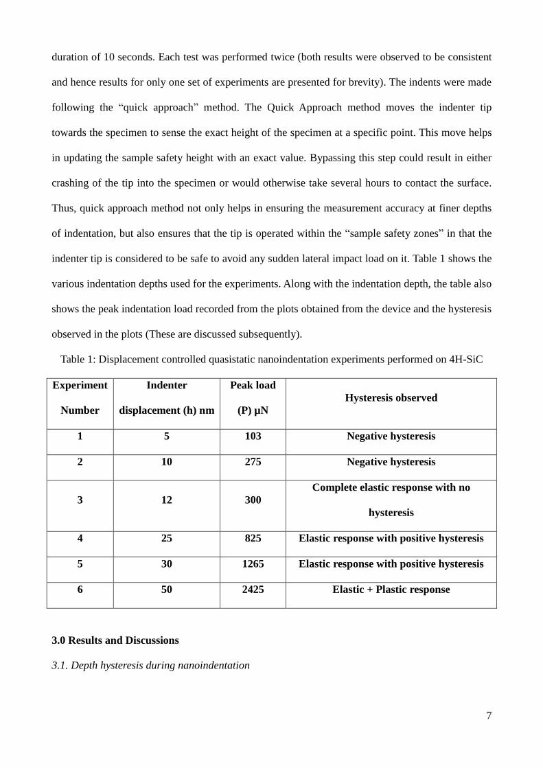
indenter tip is considered to be safe to avoid any sudden lateral impact load on it. Table 1 shows the
various indentation depths used for the experiments. Along with the indentation depth, the table also
shows the peak indentation load recorded from the plots obtained from the device and the hysteresis
observed in the plots (These are discussed subsequently).
Table 1: Displacement controlled quasistatic nanoindentation experiments performed on 4H-SiC
Experiment
Number
Indenter
displacement (h) nm
Peak load
(P) µN
Hysteresis observed
1 5 103 Negative hysteresis
2 10 275 Negative hysteresis
3 12 300
Complete elastic response with no
hysteresis
4 25 825 Elastic response with positive hysteresis
5 30 1265 Elastic response with positive hysteresis
6 50 2425 Elastic + Plastic response
3.0 Results and Discussions
3.1. Depth hysteresis during nanoindentation

8
The P-h plots for various depths of indentation performed of 4H-SiC are shown in figure 2. Figures
2(a) and 2(b) show the P-h plots for the indentation depths of 5 nm and 10 nm respectively.
(a) Indentation depth 5 nm (b) Indentation depth 10 nm
(c) Indentation depth 12 nm (d) Indentation depth 25 nm
(e) Indentation depth 30 nm (f) Indentation depth 50 nm
9
Figure 2: P-h plots for indentations made on single crystal 4H-SiC at various depths
In both the cases (figure 2a and 2b), a negative depth hysteresis of 12 µN and 20 µN respectively
can be observed from these plots. Consequently, at these indentation depths, the Oliver and Pharr
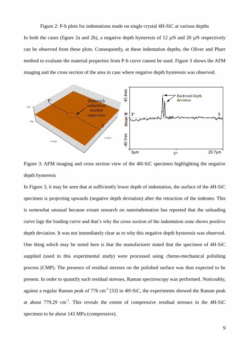
method to evaluate the material properties from P-h curve cannot be used. Figure 3 shows the AFM
imaging and the cross section of the area in case where negative depth hysteresis was observed.
Figure 3: AFM imaging and cross section view of the 4H-SiC specimen highlighting the negative
depth hysteresis
In Figure 3, it may be seen that at sufficiently lower depth of indentation, the surface of the 4H-SiC
specimen is projecting upwards (negative depth deviation) after the retraction of the indenter. This
is somewhat unusual because extant research on nanoindentation has reported that the unloading
curve lags the loading curve and that’s why the cross section of the indentation zone shows positive
depth deviation. It was not immediately clear as to why this negative depth hysteresis was observed.
One thing which may be noted here is that the manufacturer stated that the specimen of 4H-SiC
supplied (used in this experimental study) were processed using chemo-mechanical polishing
process (CMP). The presence of residual stresses on the polished surface was thus expected to be
present. In order to quantify such residual stresses, Raman spectroscopy was performed. Noticeably,
against a regular Raman peak of 776 cm-1
[33] in 4H-SiC, the experiments showed the Raman peak
at about 779.29 cm-1
. This reveals the extent of compressive residual stresses in the 4H-SiC
specimen to be about 143 MPa (compressive).

10
Based on this information, it is proposed that the negative depth hysteresis in the unloading force
could be due to the annealing and consequent thermal expansion of the surface layer of the
specimen. This could happen due to the local heating (high heat at the interface of the indenter and
the specimen due to friction) of the surface layer which helps in relieving the compressive residual
stresses that are induced in the specimen due to the polishing process carried out on the specimen
prior to the nanoindentation process. While compressive residual stresses get relieved due to
annealing, the material expands which might have caused an opposite force on the indenter leading
to this negative depth hysteresis. This phenomenon implies and aligns with the concept of backward
depth deviation which appears in the form of hogging as has been recently observed in the thin
films of Diamond like carbon (DLC) [34] and SiC [35]. This implication is also supported from the
AFM imaging shown in figure 3 which confirms the presence of negative depth deviation.
Figure 2(c) shows the P-h plot for the indentation made on 4H-SiC specimen at depth of 12 nm.
Unlike the indents performed at depths of 2 nm and 5 nm, no depth hysteresis was observed in these
plots. This implies that the material made a complete elastic recovery and unloading curve followed
the same trend like that of the loading curve. Figures 2(d), 2(e) and 2(f) show the P-h plots for the
indentation made on 4H-SiC specimen at depths of 25 nm, 30 nm and 50 nm respectively. In these
figures, the indentation plot shows a different response of the specimen i.e. the ratio of hf/hmax is less
than unity and at an indentation depth of 50 nm a clear positive depth hysteresis is observed from
these plots. As explained in the next section, this positive hysteresis is a result of the incipient
plasticity in 4H-SiC. The typical response of the 4H-SiC specimen is schematically presented in
figure 4, highlighting the behaviour of the specimen under different depth of indentations as has
been explained above.

11
(a) Indentation in 4H-SiC at lower depths of upto 10 nm
(b) Indentation in 4H-SiC at depths 12 nm
(c) Indentation in 4H-SiC at higher depths
Figure 4: Schematic of the depth hysteresis observed during nanoindentation of 4H-SiC
3.2. Incipient plasticity in 4H-SiC
Recently, grain boundary (g.b) analysis in conjunction with Large Angle Convergent Beam Electron
Diffraction (LACBED) was used to propose that that dislocations in 4H-SiC were observed to be in

12
the basal plane with their Burgers vector as 1/3<-1-120> [36]. Also, perfect dislocations in 4H-SiC
were proposed to dissociate into Shockley partials as per the following reaction:
10013
11010
3
12011
3
1 (1)
For brittle materials like 4H-SiC, there may be two types of defect nucleations: dislocations or
micro-cracks. The dislocations are induced by the onset plasticity, occurring when the maximum
shear stress beneath the indenter exceeds the theoretical shear strength of 4H-SiC. Hertzian theory
suggests that the maximum tensile stress is at the edge of the indenter. This stress acts in a radial
direction on the surface outside the indenter, and is usually responsible for the cone cracks [37].
When the tensile strength does not exceed the value of theoretical cleavage strength or when the
maximum shear stress below the indenter tip approaches the theoretical shear strength, then a pop-
in event could occur due to the incipient plasticity. Ostensibly, the pop-in event (kink showed in
figure 2f) arises from the nanomechanical response of the material, possibly due to an activity of
defect nucleation underneath the indenter [31]. The parabolic shape of the P-h curve indicates
elastic contact while displacement burst plus shallower slope is reminiscent of a combination of
elastic and plastic response. Beyond this point, the unloading curve follows the power law curve.
An analytical stress analysis was carried out to find the state of stress underneath the indenter in
order to reveal the minutiae of the pop-in event. Before the pop-in event, the P-h curve follows the
Hertzian contact theory which could be expressed using the following equation:
3
3
4RhErP (2)
where P is the indentation load, h is the displacement of the indenter, R is the radius of the indenter
(300 nm) and Er is the reduced elastic modulus where Er can be expressed as:
ir EEE
22 111
(3)
In the above expression υ and E are the Poisson’s ratio and elastic modulus of 4H-SiC [12]
respectively while Ei and υi are the elastic modulus and Poisson’s ratio of the diamond indenter

13
which were considered as 1141 GPa and 0.07 respectively. This gives the value of Er as 296 GPa
for the current combination of diamond and 4H-SiC.
In order to assert if the pop-in event in Figure 2(f) relates to the plastic deformation due to
dislocation nucleation or crack propagation, an analysis is presented below. This analysis is based
on evaluation of the maximum shear stress and maximum tensile strength underneath the indenter
during the process of nanoindentation. The maximum shear stress underneath the indenter can be
found out using the following equation [14]:
hR
P
..47.0
(4)
This gives an estimate of τ (shear stress) as 21 GPa at an indentation depth of 33 nm at a typical
indentation load (P = 1500 µN) where pop-in event was observed. To compare and correlate this
shear stress with plastic deformation, the theoretical shear strength of 4H-SiC was obtained from
the following equation [38]:
GPa 20.92π
131.4
2π
GSiC-4H ofstrength Shear (5)
where G is the shear modulus and is experimentally known to be about 131.4 GPa for 4H-SiC.
It can be seen that the shear strength of 4H-SiC (20.9 GPa) corroborates well with the shear stress
of 21 GPa estimated to be underneath the indenter during the pop-in event. This seems to suggest an
occurrence of plastic deformation in 4H-SiC underneath the indenter. It is to be noted that plastic
deformation can be affirmed if another criterion for plastic deformation is fulfilled i.e. the tensile
stresses underneath the indenter need to be lower than the cleavage strength of 4H-SiC.
The tensile stresses and cleavage strength of 4H-SiC were obtained using the following equation
[14]:
3/1
3/2
max3
4
2
21P
R
E
(6)
where σmax is the tensile strength underneath the indenter, P is the indentation load (1500 µN), υ is

14
the Poisson’s ratio (0.23) of 4H-SiC, E is the elastic modulus (347 GPa) [12] of 4H-SiC and R is the
indenter radius (300 nm).
Substitution of the experimental values in the above equation reveals the magnitude of tensile stress
to be about 10.155 GPa underneath the indenter. For fracture or cleavage to dominate over plastic
deformation, the cleavage strength of 4H-SiC must be lower than the value of this tensile stress. The
following equation was used to calculate the cleavage strength of 4H-SiC.
a
E
2
1SiC-4H ofstrength Cleavage (7)
where E is the elastic modulus of 4H-SiC (347 GPa), γ is surface tension (6.5 J/m2 [39]) and a is the
interplanar spacing (3.079 Å) in 4H-SiC.
Substitution of the above values reveals the magnitude of cleavage strength to be 13.53 GPa. Figure
5 shows the evolution of the tensile stress and shear stress underneath the indenter (the figure was
drawn using equations (2), (3), (4), (5), (6) and (7)) and highlights the theoretical shear strength and
theoretical cleavage strength of 4H-SiC.

15
Figure 5: Evolution of shear stress and tensile stress underneath the Berkovich indenter (300 nm
edge radius) during nanoindentation of nanocrystalline 4H-SiC at indentation depths up to 50 nm
It can be seen from Figure 5 and from the above calculations that the theoretical shear strength
calculation coincides with the pop-in event observed at an indentation depth of 33 nm whereas the
tensile stresses at this point were far lower (10.155 GPa). This proves that the plastic deformation in
4H-SiC during the pop-in event leads to cleavage and thus explains that the observed incipient
plasticity is due to plastic deformation rather than the micro cleavage or fracture in 4H-SiC. The
analysis presented above also reveals that during contact loading of single crystal 4H-SiC, tensile
and shear stresses underneath the indenter increase with an increase in the indentation depth. At
shallow depths of indentation (33 nm while using an indenter with the edge radius of 300 nm), the
induced shear stress is lower than the theoretical shear strength of the specimen and hence material
showed pure elastic response. With an increase in the extent of load, when the shear stress
underneath the indenter exceeds the theoretical shear strength of 4H-SiC, a pop-in event is
observed, which indicates induced plastic response. Such a plastic response is due to the plastic
deformation and not because of the crack propagation because until this point, the theoretical
cleavage strength is much higher than the tensile stress underneath the indenter.
4.0 Conclusions
Displacement controlled quasistatic nanoindentations on single crystal 4H-SiC were analyzed.
Typically below a shear stress of 21 GPa, 4H-SiC showed purely elastic response while plasticity
was observed beyond this point. Based on the foregoing discussions, following other conclusions
can be drawn:
1. Three distinct patterns in the P-h plots were observed during nanoindentation of 4H-SiC (i)
with negative depth hysteresis (ii) with no depth hysteresis and (iii) with positive depth
hysteresis. This depth hysteresis is proposed to arise from compressive residual stresses
(~143 MPa).

16
2. An analytical stress analysis was carried out to calculate the theoretical shear strength and
cleavage strength of 4H-SiC along with the shear stress and tensile stress underneath the
indenter. The theoretical shear strength was estimated to be about 20.9 GPa which was
found to corroborate with the shear stress (21GPa) underneath the indenter whereas the
theoretical cleavage strength was estimated to be 13.53 GPa which was noted to be much
higher than the estimated tensile stress of 10.155 GPa underneath the indenter. Comparison
of these values reveals that pop-in event occurred on account of plastic deformation in 4H-
SiC rather than fracture (thus indicating that the pop-in event is an outcome of the incipient
plasticity in 4H-SiC).
Acknowledgments:
Authors greatly acknowledge the funding support from J M Lessells travel scholarship from the
Royal Society of Edinburgh (2013 RSE/J M Lessells Travel Scholarship) and an additional funding
from the International Research Fellowship account of Queen’s University, Belfast. Authors also
greatly acknowledge an additional funding from an EPSRC research grant (Ref: EP/K018345/1).
References:
1. Neudeck, P.G., SiC Technology, in The VLSI Handbook, B. Raton, Editor. 2000, CRC Press
and IEEE Press: Florida. p. 6.1-6.24.
2. Dzurak, A., Quantum computing: Diamond and silicon converge. Nature, 2011. 479(7371):
p. 47-48.
3. Shore, P., Cunningham, C., DeBra, D., Evans, C., Hough, J., Gilmozzi, R., Kunzmann, H.,
Morantz, P., and Tonnellier, X., Precision engineering for astronomy and gravity science.
CIRP Annals - Manufacturing Technology, 2010. 59(2): p. 694-716.
4. Newsome, D.A., Sengupta, D., Foroutan, H., Russo, M.F., and van Duin, A.C., Oxidation of
Silicon Carbide by O2 and H2O: A ReaxFF Reactive Molecular Dynamics Study, Part I.
The Journal of Physical Chemistry C, 2012. 116(30): p. 16111-16121.
5. Coletti, C., Jaroszeski, M., Pallaoro, A., Hoff, A., Iannotta, S., and Saddow, S.
Biocompatibility and wettability of crystalline SiC and Si surfaces. in Engineering in
Medicine and Biology Society, 2007. EMBS 2007. 29th Annual International Conference of
the IEEE. 2007: IEEE.
6. Li, X., Wang, X., Bondokov, R., Morris, J., An, Y.H., and Sudarshan, T.S., Micro/nanoscale
mechanical and tribological characterization of SiC for orthopedic applications. Journal of
Biomedical Materials Research Part B: Applied Biomaterials, 2005. 72B(2): p. 353-361.
7. Coletti, C., Jaroszeski, M., Hoff, A.M., and Saddow, S.E. Culture of mammalian cells on
single crystal SiC substrates. in Mater. Res. Soc. Symp. Proc. 2006: Cambridge Univ Press.
8. Kalnins, U., Erglis, A., Dinne, I., Kumsars, I., and Jegere, S., Clinical outcomes of silicon
carbide coated stents in patients with coronary artery disease. Medical science monitor:
international medical journal of experimental and clinical research, 2002. 8(2): p. PI16-20.

17
9. Inasaki, I., Grinding of Hard and Brittle Materials. CIRP Annals - Manufacturing
Technology, 1987. 36(2): p. 463-471.
10. Komanduri, R., On Material Removal Mechanisms in Finishing of Advanced Ceramics and
Glasses. CIRP Annals - Manufacturing Technology, 1996. 45(1): p. 509-514.
11. Perrone, D., PhD Thesis, Process and characterisation techniques on 4H - Silicon Carbide,
in Micronanotechnology. 2007, Politecnico di Torino: Torino.
12. Luo, X., Goel, S., and Reuben, R.L., A quantitative assessment of nanometric machinability
of major polytypes of single crystal silicon carbide. Journal of the European Ceramic
Society, 2012. 32(12): p. 3423-3434.
13. Ravindra, D., Patten, J., and Jacobsen, R., Hybrid laser ablation–single point diamond
turning machining process for CVD–silicon carbide ceramics. International Journal of
Manufacturing Research, 2013. 8(3): p. 227-249.
14. Zhao, X., Langford, R.M., Shapiro, I.P., and Xiao, P., Onset Plastic Deformation and
Cracking Behavior of Silicon Carbide under Contact Load at Room Temperature. Journal of
the American Ceramic Society, 2011. 94(10): p. 3509-3514.
15. Patten, J., Gao, W., and Yasuto, K., Ductile Regime Nanomachining of Single-Crystal
Silicon Carbide. Journal of Manufacturing Science and Engineering, 2005. 127(3): p. 522-
532.
16. Levitas, V.I., Ma, Y., Selvi, E., Wu, J., and Patten, J.A., High-density amorphous phase of
silicon carbide obtained under large plastic shear and high pressure. Physical Review B,
2012. 85(5): p. 054114.
17. Goel, S., Luo, X., Comley, P., Reuben, R.L., and Cox, A., Brittle–ductile transition during
diamond turning of single crystal silicon carbide. International Journal of Machine Tools
and Manufacture, 2013. 65(February): p. 15-21.
18. Yan, J., Zhang, Z., and Kuriyagawa, T., Mechanism for material removal in diamond turning
of reaction-bonded silicon carbide. International Journal of Machine Tools and
Manufacture, 2009. 49(5): p. 366-374.
19. Shayan, A.R., Poyraz, H.B., Ravindra, D., Ghantasala, M., and Patten, J.A., Force Analysis,
Mechanical Energy and Laser Heating Evaluation of Scratch Tests on Silicon Carbide (4H-
SiC) in Micro-Laser Assisted Machining ([micro sign]-LAM) Process. ASME Conference
Proceedings, 2009. 2009(43611): p. 827-832.
20. Ravindra, D. and J.A., P., Determining the Ductile to Brittle Transition (DBT) of a Single-
Crystal 4H-SiC Wafer by Performing Nanometric Cutting, in ISAAT 2007 Precision
Grinding and Abrasive Technology at SME International Grinding Conference. 2007.
21. Patten, J.A., Jacob, J., Bhattacharya, B., Andrew Grevstad, Ning Fang, and Marsh, E.R.,
Chapter 2: Numerical simulations and cutting experiments on single point diamond
machining of semiconductors and ceramics, in Semiconductor Machining at the Micro-Nano
Scale, ISBN : 978-81-7895-301-4, J. Yan and J.A. Patten, Editors. 2007, Transworld
Research Network: Trivandrum-695 023, Kerala, India.
22. Bhattacharya, B., Patten, J.A., and Jacob, J., Single Point Diamond Turning of CVD Coated
Silicon Carbide. ASME Conference Proceedings, 2006. 2006(47624): p. 1153-1158.
23. Schuh, C.A. and Lund, A.C., Application of nucleation theory to the rate dependence of
incipient plasticity during nanoindentation. Journal of Materials Research, 2004. 19(07): p.
2152-2158.
24. V.C. Venkatesh and Sudin Izman, Precision Engineering, DOI: 10.1036/0071548270. 2007,
New Delhi, India: Tata Macgraw Hill.
25. Chen, X., Hutchinson, J.W., and Evans, A.G., The mechanics of indentation induced lateral
cracking. Journal of the American Ceramic Society, 2005. 88(5): p. 1233-1238.
26. Ravindra, D., Ductile mode material removal of ceramics and semiconductors, in
Department of Mechanical and Aeronautical Engineering. 2011, Western Michigan
University: Michigan. p. 312.
27. Niihara, K., Slip systems and plastic deformation of silicon carbide single crystals at high

18
temperatures. Journal of the Less Common Metals, 1979. 65(1): p. 155-166.
28. Probe Selection Guide - Hysitron Triboindenter Manual, H. Incorporated, Editor. 2007:
Minneapolis, USA.
29. Javvaji, R., Nanoscale ductile mode ultraprecision cutting of potassium dihydrogen
phosphate, in Mechanical Engineering. 2008, National University of singapore: Singapore.
30. Faisal, N., Ahmed, R., and Reuben, R., Indentation testing and its acoustic emission
response: applications and emerging trends. International Materials Reviews, 2011. 56(2):
p. 98-142.
31. Schuh, C.A., Nanoindentation studies of materials. Materials Today, 2006. 9(5): p. 32-40.
32. Kruzic, J.J., Kim, D.K., Koester, K.J., and Ritchie, R.O., Indentation techniques for
evaluating the fracture toughness of biomaterials and hard tissues. Journal of the
Mechanical Behavior of Biomedical Materials, 2009. 2(4): p. 384-395.
33. Feldman, D., Parker Jr, J.H., Choyke, W., and Patrick, L., Phonon dispersion curves by
Raman scattering in SiC, polytypes 3C, 4H, 6H, 15R, and 21R. Physical Review, 1968.
173(3): p. 787.
34. Faisal, N.H., Ahmed, R., Fu, Y.Q., Elakwah, Y.O., and Alhoshan, M., Influence of indenter
shape on DLC film failure during multiple load cycle nanoindentation. Materials Science
and Technology, 2012. 28(9-10): p. 1186-1197.
35. Dharma Raju, T., Kato, M., and Nakasa, K., Backward deviation and depth recovery of
load–displacement curves of amorphous SiC film under repeating nanoindentation. Acta
Materialia, 2003. 51(12): p. 3585-3595.
36. Demenet, J.-L., Amer, M., Tromas, C., Eyidi, D., and Rabier, J., Dislocations in 4H- and
3C-SiC single crystals in the brittle regime. physica status solidi (c), 2013. 10(1): p. 64-67.
37. Buzio, R., Boragno, C., Biscarini, F., De Mongeot, F.B., and Valbusa, U., The contact
mechanics of fractal surfaces. Nature Materials, 2003. 2(4): p. 233-236.
38. Gouldstone, A., Koh, H.J., Zeng, K.Y., Giannakopoulos, A.E., and Suresh, S., Discrete and
continuous deformation during nanoindentation of thin films. Acta Materialia, 2000. 48(9):
p. 2277-2295.
39. Otubo, H., Yamamoto, Y., Takekuni, H., and Nishitani, S.R., First principles calculations of
relaxed and reconstructed surfaces of SiC. Accessed through google.com on 26.8.2013.


![Chapter 2 SiC Materials and Processing Technology€¦ · 34 2 SiC Materials and Processing Technology Table 2.1 Key electrical parameters of SiC [1] Property 4H-SiC 6H-SiC 3C-SiC](https://static.fdocuments.in/doc/165x107/5f4fd11797ddad63bf719816/chapter-2-sic-materials-and-processing-technology-34-2-sic-materials-and-processing.jpg)


