Incinerator Air Pollution Control - Columbia University · INCINERATOR AIR POLLUTION CONTROL J. H....
16
INCINERATOR AIR POLLUTION CONTROL J. H. FERNANDES Combustion Engineering, Inc. Windsor, nnecticut ABSTRACT Incinerators offer a solution to the solid waste dis- posal problems of the country if the particulate emission is controlled. This paper reviews and discusses the emis- sion problem, the various methods of incinerator particu- late emission control, and the relative cost. Preliminary cost versus performance estimates may be approximated using the parameters presented in this paper. An exten- sive bibliography is included. INTRODUCTION The problem of refuse disposal is inextricably involved with the problem of air pollution regardless of the method of disposal. Incineration offers the opportunity to reduce refuse to a sterile landfill and remove offensive odors, but it can be a significant contributor to the air pollution problem in an urban community. The primary air pollu- tion concern in incineration is with particulate emission rather than gases or odors, therefore, the emphasis here is, on particulate emission. There have been comments that a properly operated incinerator does not need particulate collection equip- ment. Many systems with little or no air pollution con- trol equipment have been represented as effectively meeting dust emission requements when they actually do not. This occurs because the excess air used for com- bustion and cooling is so eat (200 to 500 percent) that it dilutes the effluent to the extent that it does not ap- 101 pear objectionable, although excessive quantities of dust are actually emitted. With the trend toward larger, more efficient incinerators located close to the population centers served, effective control of incinerator atmos- pheric pollution is extremely important. The degree of gas cleaning required and the costs of primary control equipment will be discussed in this paper. Relative cost for various deees of control will also be presented. The discussion will concentrate on air pollution control of the large continuously fed incinera- tor now common in modern municipal practice. INCINERATOR PARTICULATE EMISSION The quantity and size of particulate emission leaving the furnace of an incinerator varies widely, depending on such factors as the refuse being fired, method of feeding, operating procedures, and completeness of com- bustion. The information presented in this paper includes test results obtained by Combustion Engineering, Inc. and published data from a number of other sources. The rate of furnace dust emission has been found to vy from less than 10 lb to as much as 60 lb of dust per ton of refuse burned. High-performance, compact, turbu- lent incinerators operate close to the middle of this range, or about 35 lb per ton. In practice, dust loadings are re- ported in various ways. This 35 lb per ton may be re- ported as: • 3.5 lb per million Btu (assuming 5000 Btu per lb of refuse).
Transcript of Incinerator Air Pollution Control - Columbia University · INCINERATOR AIR POLLUTION CONTROL J. H....

INCINERATOR AIR
POLLUTION CONTROL
J. H. FERNANDES Combustion Engineering, Inc.
Windsor, Connecticut
ABSTRACT
Incinerators offer a solution to the solid waste disposal problems of the country if the particulate emission is controlled. This paper reviews and discusses the emission problem, the various methods of incinerator particulate emission control, and the relative cost. Preliminary cost versus performance estimates may be approximated using the parameters presented in this paper. An extensive bibliography is included.
INTRODUCTION
The problem of refuse disposal is inextricably involved with the problem of air pollution regardless of the method of disposal. Incineration offers the opportunity to reduce refuse to a sterile landfill and remove offensive odors, but it can be a significant contributor to the air pollution problem in an urban community. The primary air pollution concern in incineration is with particulate emission rather than gases or odors, therefore, the emphasis here is, on particulate emission.
There have been comments that a properly operated incinerator does not need particulate collection equipment. Many systems with little or no air pollution control equipment have been represented as effectively meeting dust emission requirements when they actually do not. This occurs because the excess air used for combustion and cooling is so great (200 to 500 percent) that it dilutes the effluent to the extent that it does not ap-
101
pear objectionable, although excessive quantities of dust are actually emitted. With the trend toward larger, more efficient incinerators located close to the population centers served, effective control of incinerator atmospheric pollution is extremely important.
The degree of gas cleaning required and the costs of primary control equipment will be discussed in this paper. Relative cost for various degrees of control will also be presented. The discussion will concentrate on air pollution control of the large continuously fed incinerator now common in modern municipal practice.
INCINERATOR PARTICULATE EMISSION
The quantity and size of particulate emission leaving the furnace of an incinerator varies widely, depending on such factors as the refuse being fired, method of feeding, operating procedures, and completeness of combustion. The information presented in this paper includes test results obtained by Combustion Engineering, Inc. and published data from a number of other sources.
The rate of furnace dust emission has been found to vary from less than 10 lb to as much as 60 lb of dust per ton of refuse burned. High-performance, compact, turbulent incinerators operate close to the middle of this range, or about 35 lb per ton. In practice, dust loadings are reported in various ways. This 35 lb per ton may be reported as:
• 3.5 lb per million Btu (assuming 5000 Btu per lb of refuse).

• 2.97 lb of dust per 1000 lb of flue gas adjusted to 50 percent excess air (corrected to a flue gas condition equivalent to burning with 1.5 times the theoretical air required).
• 1.58 grains per standard ft3 adjusted to 50 percent excess air.
These dust loadings refer to conditions "leaving the furnace" (leaving the combustion zone, including any after-burner or secondary furnace, but before the quench chamber).
Dust sizing, like dust loading, varies widely. Most factors which affect dust loading also affect dust sizing. Improved incinerator performance, which reduces dust quantities, also decreases the size of the individual particles. The dust is always quite heterogenous, consisting of rather typical incinerator fly ash combined with large, low-density flakes. Dust density varies from a� average of slightly over 2 grams per cc (125 lb per ft ) to as high as 3 grams per cc (187 per ft3). The dust size as determined in the BAHCO centrifugal classifier, using the methods and procedures of ASME Performance Test Code No. 28, indicate a size-range distribution as presented in Fig. 1. It is evident that about 35 percent of
0
100 90 8 70 60 50
40
V> Z o 0:20 u � 0: ... ... ... :IE .q o ... ...J U � 0: �
10 9 8 7 6
3
2
I
. CUMULATI�:,.
;"�RDT�;� SIZE DISTRIBUTION
",n I 1I!Sl§ 'W
� rRANGE 'VALUES
&. II< 'a � flI ��
� IW
IJ,'W i ��
If'
, A I 001 O.O!! OJ 02 o.� I 2 � 10 20 30 '10 50 60 70 80 90 "
PERCENT BY WEIGHT LESS THAN SlZ£ INDICATED
FIG. 1 PARTICLE SIZE DISTRIBUTION FOR INCINERA TOR
FLYASH
102
the average dust leaving the furnace is below ten microns (1 micron = 3.94 X 10⁻⁵ in.) and is difficult to collect. Simple settling chambers and spray chambers do not remove sufficient quantities of this dust to meet even lenient air pollution regulations, therefore, more sophisticated equipment must be used.
EMISSION STANDARDS-
The foregoing discussion indicates the size and quantity of the dust generated in a modern, well-run incinerator. The question still remains, as to how much of this may be emitted to the atmasphere. Present practice usually attempts to control up to 0.85 lb of fly ash per 1000 lb of flue gas, adjusted to 50 percent excess air (lIb per 106 Btu), as suggested in the "1949 ASME Example for a Smoke Regulation Ordinance". The ASME published a new suggested regulation in 1966 entitled "Recommended Guide for the Control of Dust Emission - Combustion for Indirect Heat Exchangers." It seems reasonable to assume that this document will receive the same widespread acceptance that the earlier ordinance did. Thus, future codes can be expected to lower the allowable emission from 1. 0 to 0.80 lb of fly ash per million Btu, or to 0.68 lb of dust per 1000 lb of gas corrected to 50 percent excess air. Larger, more congested metropolitan areas or areas with adverse topography, such as the Los Angeles Basin, may adopt the recent Federal Facilities Regulations published in the Federal Register, Volume 31, No. 197, June 3, 1966. These regulations limit emissions to 0.20 grains per standard ft3 at 50 percent excess air (0.44 lb of dust per million Btu fired) for incinerator capacities of 200 lb per hr (1.4 tons per day) and larger. Fig. 2 has been included to illustrate these various control standards.
INCINERATOR AIR POLLUTION CONTROL EQUIPMENT
An early method of fly-ash reduction was the dry settling chamber. The reduced gas velocities and dropout of the larger particles, many containing unburned carbon, permitted burnout of the carbon. Up to about 20 percent of the ash dust in the gases was deposited. Because the large settling chamber requires considerable space and is insufficient for the complete gas cleaning task, it is not expected to be used as frequently in the future. Nevertheless, it is assumed that space, time, and turbulence will be provided for good burnout of suspended combustibles before dust collection is undertaken.

MAXIMUM ALLOWABLE PARTICULATE EMISSION
FOR COMBUSTION UNITS
_ 0.450 � 0.405 .. 0.360
_ 0.850 It: 0.765 or 0.680 ::l 0.595
1.0 0.9 Q8
1949 ASME SMOKE REGULATION ORDINANCE
1966 AS ME MAXIMUM RECOMMENDED EMISSION LEVEL
.., ::l 0.315 t;: tl 0270 0)( It: W 0.225 .. � 0 �� .180 .. Iii 0 OJ35 ..... � 11)0 ZW or t 0.090 It:W "It:
It: 8
�tl 0.510 "x ww 0:425 ':J� i1.� 0.340 CD §� 0.225
_w ;D ti 0.170 .... w
It: It: o u
I- 0.7
i Q6
� Q5
� 0.4 CD z o 0.3 :::i .... � 02 CD ....
0.045 0.085 O. I OUST EMISSION
TC OMPL'I' WI H EXE 'IV£ mH!£RITZW2
5 10 50 100 5 00 FUEL: TOTAL INPUT, MILLIONS OF BTU PER HOUR I STOKER- FIRED REFUSE
HHV- 5000 BTU/LB
EXTRACTED FROM:
2.4
FEDERAL REGISTER, VOL. 3L, No. 107,6-3-66 ASME STANDARD, No. APS-I, 6-15-66
12 24 120 240 1200
TONS PER DAY
FIG. 2 EMISSION CONTROL STANDARDS
The combined settling chamber-water spray gas cooler can remove up to 30 percent of the fly ash leaving the furnace. Today, the combined chamber may be quite small if its essential purpose is water quenching of the gas to a temperature acceptable to the air pollution control equipment and induced-draft fans. The temperature of gases leaving such spray chambers is usually about 600 F. If on the other hand, the gas shrinking and cooling is accomplished by indirect heat exchange, such as in a boiler or gas-to-air heat exchanger, a settling chamber may not be required.
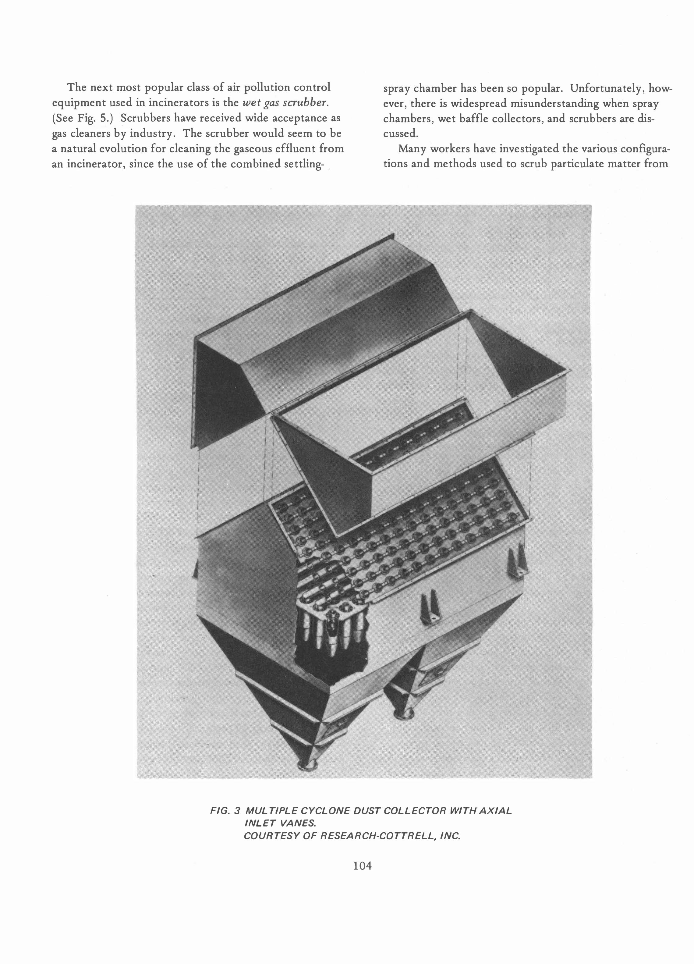
The mechanical (cyclone) collector is the next step up the ladder of air pollution control equipment both in performance and cost. There are two basic types - the multi-cyclone or the large involute cyclone. The multicyclone unit (Fig. 3) is made up of numerous axial inlet (vaned) mechanical collecting tubes, which vary in diameter form 6 to 10 in. and are arranged in a tube sheet to receive the incoming dirty gas. The inlet spinner vanes impart a swirl to the gas which creates a strong vortex within the main tube. This vortex centrifugally separates the dust from the gas stream and allows the clean gas to proceed to the outlet tube which connects to a second tube sheet. This sheet partitions the inlet dirty gas from the leaving clean gas. Separated dust moves down to the lower outlet and settles in the dust hopper.
103
Multi-cyclones are in common use in industry today and most of their performance parameters are known. This type of collector is extremely efficient on large particles, but performance drops off rapidly for dust sizes smaller than 20 microns (78.74 x 10⁻⁵ in.) and they are not very satisfactory on dust sizes less than 10 microns where about 35 percent by weight of the incinerator fly ash falls. (See Fig. 1.) Flow through the dust hopper caused by leakage or gas flowing out of one tube and into another can seriously affect performance. Intertubular flow is always present unless inlet gas distribution is perfect and no tube plugging occurs. Sticky or wet dust may plug the inlet spinner vanes and can cause cross hopper flow. When no cross hopper flow occurs and the vortex is sufficiently strong (3% in. wc pressure drop), the multi-cyclone dust collector can attain 80 percent collection efficiency on incinerator fly ash, but if about a third of the tubes become plugged, the efficiency may drop to as low as 20 percent.
The second type of mechanical collector, the large (over 2 ft in diameter) involute-type cyclone, operates on the same basic principle as the multi-cyclone. (See Fig. 4.) Its performance is usually similar to that of the multicyclone except when it is equipped with a flow-splitting inlet manifold and separate dust hoppers. This arrangement is usually free of plugging and cross-hopper flow ··,roblems.
The next most popular class of air pollution control equipment used in incinerators is the wet gas scrubber. (See Fig. 5.) Scrubbers have received wide acceptance as gas cleaners by industry. The scrubber would seem to be a natural evolution for cleaning the gaseous effluent from an incinerator, since the use of the combined settling-
•
f • j ,
I f
I 1 I I f 1
, f I - I
-
•
spray chamber has been so popular. Unfortunately, however, there is widespread misunderstanding when spray chambers, wet baffle collectors, and scrubbers are discussed.
Many workers have investigated the various configurations and methods used to scrub particulate matter from
1 r i
FIG. 3 MUL TlPLE CYCLONE DUST COLLECTOR WITH AXIAL INLET VANES. COURTESY OF RESEARCH-COTTRELL, INC.
104

•
I I I I I I
I I I I I I I
I I
I�
LI
u
-
- ..
'r-_ r-o-
: ,..-_.-::::!o!:===-__ I�O���
u u
u
u u
- - -- - --
FIG. 4 CYCLONE DUST COLLECTOR OF IN VOL UTE TYPE COUNTESY OF RESEARCH-COTTRELL, INC.
105
u

ANTI-SPAN VANES AND MIS T E LIMINATOR
CORE BUSTER
GAS OUT
t
D ISK -----+-�
DAMPER '---SPRAY M ANIFOLD
CYCLONIC SPRAY SCRUBBER
ENTRA I NMENT SEPARATOR
BAFFLE S
DUSTY GAS IN-
-CLE AN GAS OU T
��5;iiL=;TYPICAL PAC KING
BE D
TYPICAL WATER SPRAY
l#.����=�WATER INLE T 9/,' � � ,� �:s0�
WATER OUT
PACKED SCRUBBER
FIG. 5 WET GAS SCRUBBERS
106

gases, and certain facts are known. The dust particle must impact on the water droplet to be removed, and the impaction efficiency is primarily a function of the following parameters: the relative velocity between the water droplet and the dust particle, the size and density of the dust, the number of water droplets, and the fineness of the spray. Because collection efficiency is vitally dependent on relative velocity and drop size, the collection efficiency is found to be a function of the power supplied to the unit.
The true wet scrubber has been used in a few municipal incinerators operated in the range of 6. 0 to 8.0 in. wc pressure drop, and having a fly ash removal efficiency in the range of 90 to 97 percent. It has the advantages of compactness and low first cost when compared with other high-efficiency collectors. In order to meet the high particulate removal efficiencies indicated, the equipment normally produces flue gas which is saturated at the wet bulb temperature of the recirculating water. The specific
FIG. 6 EL ECTROSTATIC PRECIPITATOR
COURTESY OF RESEARCH-COTTRELL, INC.
107

humidity of the stack effluent is, therefore, relatively high. A characteristic, then, of the wet scrubber installation is an almost continuous vapor plume at the top of the stack. While this plume is not an air pollutant per se, it has the appearance of being one. The trend towards low opacity requirements in air pollution regulations may require the elimination of the plume. To accomplish this, the gas must be subcooled to condense out the water and then it must be reheated to obtain a dry plume with sufficient buoyancy.
The amount of water required in scrubbers is high, and this may introduce a disposal problem. If, in the interest of economy, recirculation of the scrubber water is practiced, the recirculated water must be suitably conditioned. Indications are that the necessary chemical treatment is complicated and to date few incinerator/scrubber systems have performed satisfactorily with recirculation. Even with chemical treatment, scrubber maintenance problems may be affected by the absorption of gaseous acid-forming products of combustion by the scrubbing water. Unless materials of construction are carefully selected, maintenance costs and down time may be high, both for the scrubber induced-draft fans and other components in contact with the gas stream.
It should be noted that when adequate power is employed, scrubbers are capable of high-efficiency dust collection; they are nonselective as to the particle composition, and they are capable of removing certain gaseous air pollutants.
The next class of air pollution control equipment to be considered is the electrostatic precipitator. (See Fig. 6.)
This device has been used in industry for over 50 years and has built an enviable reputation. In spite of this, there are no precipitators operating on incinerators in the United States at this time. New York City has recently purchased two for incinerators, and their successful operation may signal a new era for the electrostatic precipitator.
Before discussing a few of the major factors to be considered in the selection of an electrostatic precipitator, it is best to understand the process fundamentals. Simply stated, a precipitator operates by inducing an electrostatic charge on dust particles by means of a high-voltage corona discharge. The charged dust-ladened gas is passed through an electrical field where the particles are attracted to the grounded collecting surface and the cleaned gas passes to the clean gas outlet. This basic theory is simple, but the performance of a precipitator is affected by complex relationships with a great number of interrelated parameters.
108
•
The strength of the electric field is one of the significant factors that influence collection efficiency, as is the
charging voltage which can range from about 40,000 to over 70,000 volts.
Other factors which affect dust migration to the collecting plates include dust resistivity, gas temperature, moisture content of the gas, percent of design rating (gas velocity) , flow distribution, and carbon content of the fly ash.
It has been found that for proper collection efficiency, the fly ash resistivity should be between 1 x 10⁵ to 2 X
1010 ohm-centimeters. Dusts with a resistivity less than 1 x 10⁵ ohm-centimeters are difficult or impossible to precipitate, while dust with resistivity greater than 2 x 10¹⁰
ohm-centimeters may be collected if the gas is first treated to reduce the resistivity.
Once the charged particles have been deposited on the collection plate, several processes may be used to remove the dust to the hopper. These include washing, vibrating, and rapping. The dislodged particles are agglomerated into large lumps of dust and settle into the collection hopper. Experience indicates that incinerator fly ash is fme and fairly sticky and will accumulate on discharge and collection electrodes and in hoppers normally used for coal fly ash collection. Therefore, special provisions for removal of collected material must be provided.
The main advantage of precipitators is that they can be designed for nearly any efficiency required, can operate over a broad spectrum of fly ash concentration and size, and require a nominal draft loss of only about V2 to 1 in. wc. On properly operating incinerators, precipitators have the potential of collecting more than 95 percent of the dust emitted from the furnace and they can collect submicron size particles with nearly the same facility as 100 micron particles. Thus, the electrostatic precipitator can effectively remove entrained fly ash from incinerator gases to any desired degree, and the purchaser may match the size and cost of his equipment to the predicted control requirements.
The electrostatic precipitator is capable of high efficiency operation if properly designed for the widely differing service encountered in incineration practice. It is, therefore, reasonable to predict that this country will eventually follow European practice, and use precipitators extensively on incinerators.
The final class of air pollution control equipment to be discussed is the fabric filter collector. (See Fig. 7. ) Application of the fabric collector to incinerators is still in the preliminary stage of development because of the high temperature gases and the characteristics of the fly ash.

The fabric collector is one of the original gas cleaning devices, and much experience is available from other industries. It has the ability to remove 99.9 percent of the particulate matter, thus insuring practically complete elimination of the plume opacity and making it a very desirable air pollution control system. In fabric filters, the gas passes through fabric which is usually arranged as tubular bags. The accumulated filter cake on the fabric fIlter removes the fly ash from the gas stream. Various methods are used to clean the filter - mechanical shaking, reverse jet blowing, bag collapse, and reverse flow backwash. The released fIlter cake falls to the dust hopper for removal. In one type of fabric fIlter collector, the dust-laden gas enters through the top, passes through the bag filter while giving up its dust load, and the clean gas proceeds to the stack. Filter efficiencies approach 100 percent, but their overall pressure loss may be as high as 5 to 7 in. of water.
The ftlterhouse has not been considered sooner for incinerators because both the cost of the initial ftlterhouse and the bag replacements have been prohibitive. Newer
BAG FILTERS IN OPERATION
INLET DAMPER CLOSED FOR
CLEANING
materials which guarantee long ftlter life at higher temperatures have opened the way to the practical application of filter collectors to incinerators. For example, glass cloths now allow operation at 500 F, only 100 F below present exit gas temperature levels. Some research and development work will be required, however, to insure the desired results and incinerator purchasers will have to become accustomed to the higher cost and space requirements for th� type of air pollution control equipment. The application of these collectors to incinerators will require even greater control of combustion and moisture to prevent the formation of sticky soot which blinds the ftlter cloth. Cooling of the gases must be carefully controlled to avoid formation of moisture on the fabric. Either evaporative spray cooling to 7 00 F with no wetting of the spray chamber followed by cool air dilution to 500 F, or indirect heat exchange to 500 F are feasible methods of gas conditioning.
It should be noted that air pollution control equipment performance is significantly affected by the completeness of combustion, operating procedures, and the adequacy of maintenance.
BAG FILTERS COLLAPSED
FOR CLEANING
DIRTY AIR
INLET
AUXILIARY FAN
FIG. 7 FABRIC FIL TER DUST COLLECTOR (BAG FIL TER)
109

To insure proper collection performance with any of the systems discussed, frequent and thorough inspection and maintenance of air pollution control equipment is required. Without proper maintenance, design performance as an operating criterion is meaningless. As a further check on proper performance, stack emission checks should be performed occasionally.
INCINERATOR AIR POLLUTION CONTROL EQUIPMENT PERFORMANCE
Now that each of the major classes of air pollution control equipment has been discussed, their performance will be studied in greater depth. Particulate collection equipment performance may be classified in a number of ways, but the most widely accepted criterion is the weight efficiency. The weight efficiency relates the quan-
·
tity of the dust collected to the dust that enters the col-lector with the gas. This number may be meaningfully applied only under conditions similar to those entering the collector during the test, including the given dust density and size distribution, the entering gas dust loading, the collector energy level, and the inlet gas temperature. The results can sometimes be related to other applications if the dust density, size distribution, dust resistivity (if a precipitator), collector energy level, and gas condition are known.
Another important collector performance criterion is the fractional efficiency curve (Fig. 8), sometimes called the size or grade efficiency curve. It represents the performance of the particular collector on each size of dust particle of a given density for a given collector energy level, gas temperature, and dust resistivity (if a precipitator) .
TYPICAL FRACTIONAL EFFICIENCY CURVE
.... � C) -
L&J 3 > en � 0
..
> u Z L&J -
u -
u.
u. L&J L&J N -
C/)
IOO ------�-----r----��� ___
9Or-------�-------+�
80
70
60
50
40
30
20 DUST COLLECTOR PERFORMANCE
CURVE-INCINERATOR
CONDITIONS: I 10 I- �---+-----+---�-==�T�E�M�PERATURE - 600 F
o o 5
PRESSURE DROP-3" H20
10 15 20 25
PARTICLE SIZE. MICRONS (Jl)
FIG. 8 TYPICAL FRACTIONAL EFFICIENCY CUR VE FOR DUST COLLECTORS
110
30 35

The two efficiencies are related and can be computed one from the other if the dust size distribution is known. This is very important since most air pollution control equipment manufacturers would prefer to guarantee the known fractional efficiency performance for their equipment and allow each purchaser to compute the efficiency for his particular dust.
lection equipment. A make-shift arrangement to accommodate sampling at a later date is, at best, a compromise. Pre-engineered sampling points will permit accurate measurement of particulate emission from the stack and the testing of the primary air pollution control equipment to determine if it is functioning properly.
Collector performance and the resulting emission to The size and composition of incinerator fly ash and
the extremely large quantities of air used in incineration mask the real pollution potential. As a result, stack observations are no measure of an incinerator's pollution control. An accurate determination of stack emissions can be obtained only by actual tests based on samples taken in the duct leaving the air pollution control equipment. It is suggested that test connections be designed into the ducting before and after the primary dust col-
the atmosphere are summarized in Fig. 9. This can be compared to the local emission standards which may be used as an entry to the graph. The efficiency required is read on the left ordinate while the right ordinate presents the class of air pollution control equipment that could be designed to meet this requirement. As an example, if the ASME 1966 maximum emission level from Fig. 2 is used, one can enter Fig. 9 with the 0.8 lb of dust per million Btu and read 77 percent efficiency on the left ordi-
•
� X
1 00
90 ----'
80----+ ED CONDITIONS:
� 70 f------+--I&J
150% EXCESS A IR
WATER QUENCH FROM FURN ACE TEMPERATURE
� � 60 f------+----+--' m 600 F ENTERING COLLECTOR
HIGHER HE ATING VALUE-� �f-----�----�----� Z 5000 BTU/LB I&J -(,) -
It &&J 0:: � (,) I&J ...J ...J 8
40�---�----+-----+---
30�---+---;----r----+ 35 LB DUST ENTERING COLLECTOR PER TON OF REFUSE -----+-�
20�---+---;----r----+----
10
o ______ � __ __ � __ __ � ______ � ____ �--� o 0.50 1.00 1.50 2.00 2.50 L8 D IIOOOL8 OF GAS CORRECTED TO 50·4 EXCESS AIR
o Q50 100 1.50 200 2� �
o
LB DUST I MILLION 8TU
1.�5
GRAINS DUST I S.C.F. CORRECTED TO 5OCY. EXCESS AIR
- STACK DUST EMISSION-
0.25 0.50 0.75 1.00 1.50 1.58
FIG. 9 COLLECTOR EFFICIENCY VERSUS STACK DUST EMISSIONS
111 -
EQUIPMENT
FABRIC ALTER
- ELECTROSTATIC PRECIPITATOR
---- SCRUBBER
MECHA NIC A L COLLECTOR
CHA MBER WET OR DRY

nate and on the right ordinate note that a mechanical collector could be designed for this service. Once again, the reader is cautioned that this data assumes a properly designed and maintained collector and an incinerator with good combustion conditions. The ranges of performance presented on the right ordinate of this figure indicate areas in which it is reasonable to expect each class of equipment to perform. In most cases, the 35 lb of dust per ton of refuse leaving the furnace, assumed as a basis for this graph, is a satisfactory starting point. If, for a
certain type of incinerator, the designer knows the furnace emission is greater or less than the assumed 35 lb per ton, a second line can be drawn (from the 100 percent efficiency and zero emission point to the expected furnace emission on the zero efficiency line) and the graph used
� I o -
700
650
600
550
500
)( 450 :::!! lL. u
- 400 (/) <I C> w 350 :J -.J lL. a:: 300 o t-<I a:: 250 w z -� 200 -
150
100
50
, � o
�
as before for these new conditions. This graph illustrates that today's technology can pro
vide good pollution control on modern incinerators. As mentioned earlier, the highest efficiency collectors may
INCINERATOR FLUE GA S
FLOW COMPARISON
150% EXCESS AIR
GOOF ENTERING COLL ECTOR
520 CFMITPD
WATER QUENCHE D "
150% EXCESS AIR
INDIRECT COOLING TO 600 F
NO QUENCHING
365 CFM/TPD
....t
50% EXCESS AIR
INDIRECT CO OLING TO 600 F
NO QU ENCHING 220 CFM I TPD
o 100 200 300 400 500 600 700 800 900 1000 1100 INCINERATOR RATING. TONS PER DAY
FIG. 10 INCINERATOR FLUE GAS VOLUMES WITH THREE METHODS OF OPERA TlON
112

require additional development to achieve their full potential, but they are available to the industry today.
COST OF AIR POLLUTION CONTROL EQUIPMENT FOR INCINERATORS
It is extremely difficult to precisely pinpoint the price of a particular class of air pollution control equipment. Prices vary substantially from one vendor to another, and with market conditions. In addition to these factors, certain improvements in performance and reliability cost more than less sophisticated designs of the same class. As an example, one company has developed a mechanical cyclone separator which extends the high-efficiency operation well below the usual 20 micron size, but it is larger and costs more. Therefore, all values presented in this section must be considered estimates representative of a range of possible values. The local architect-engineer involved in a particular design is best equipped to estimate the cost of the air pollution control equipment for a given plant.
The approximate cost of air pollution control equipment per ton per day of incinerator capacity can be developed on the basis of the following assumptions; 1) 600 F inlet gas temperature, 2) 150 percent excess air, 3) 5000 Btu per pound refuse.
The volume of gas handled is approximately 520 CFM per ton per day of capacity if the gas cooling is accomplished with water quenching to 600 F. If the cooling is performed indirectly by water heating, steam generating surfaces, or an air heating device, the quantity of gas to be handled is substantially reduced. (See Fig. 10.) In this case, the volume of gas to be handled is approximately 365 CFM per ton per day of capacity. If combustion is completed with 50 percent excess air and a steam generating surface is used to control furnace temperatures and cool the gas to 600 F, the volume of gas is reduced to approximately 220 CFM per ton per day of capacity (Fig. 10).
In the course of this study, many sources were searched for the cost of air pollution control equipment. The most authoritative data obtained came from statements given before the US Senate Committee on Public Works, Subcommittee on Air and Water Pollution, May 18, 1967 by Mr. Earl L. Wilson, president of the Industrial Gas Cleaning Institute, Inc. This data is included here since all
other reliable information falls within these broad ranges.
113
$/CFM* $/CFM $/CFM Yearly Equipment Erection Maintenance &
Type of Collector Cost Cost Repair Cost
Mechanical collector $.07 - $ .25 $.03- $.12 $.005- $.02
Electrostatic precipitator .25- 1.00 .12- .50 .01 - .025
Fabric filter .35- 1.25 .25- .50 .02 - .08
Wet scrubber .10- .40 _04- .16 .02 - .05
*Dollars per actual cubic foot of gas handled
It should be noted that because of the difficulties involved with the collection of incinerator fly ash, the actual cost of incinerator air pollution control equipment would probably be found at the higher ends of the ranges given. These cost ranges also account for the decrease in price with increase in unit size.
By way of illustration, a 95 percent efficient electrostatic precipitator on a 400-ton-per-day incinerator operated in accordance with the foregoing assumptions (520
CFM per ton per day) would have the following cost:
520 x 400 - 208,000 CFM
208,000 x $_80 - $166,400 fob manufacturer
208,000 x .40 = 83,200 delivery and erection cost
Total delivered and erection cost $249,600
The reader is again cautioned that these values are only first approximations. The individual plant under consideration should be studied by the architect-engineer and air pollution control equipment manufacturers, and the actual cost estimated.
Fig. 10 graphically illustrates the capital cost reduction for air pollution control equipment, ID fan, ducting, and stack when the flue gas is cooled indirectly. This difference justifies serious consideration of the utilization of the heat generated in an incinerator. If the energy released was used to supply the power to run the incinerator plant or to heat the plant and surrounding buildings, the savings in capital cost due to the reduced size of the air pollution control and gas handling equipment plus the energy savings could offset the additional cost of the heat conversion equipment. The operating savings could
,
possibly reduce the cost of incinerating the refuse. There are excellent opportunities. in the field of incinerator heat utilization, but additional research is needed if it is to develop to its full potential.

A reduction in flue gas temperature to 600 F was assumed for the examples presented here, but an additional reduction in size and cost of gas handling equipment is possible if the flue gas is indirectly cooled even further. Indications are that it may be possible to reduce the incinerator flue gas temperature to 350 F or less before release to the atmosphere. This would decrease the gas volume to be handled by nearly 15 percent. The additional heat recovery could make energy utilization even
•
more attractive. Table I is presented to summarize the interrelation
ship and comparison of the various air pollution control
equipment systems with respect to performance, size, and cost. The second column introduces a new and important parameter, the space required by each class of system. Column six presents a very important factor that is frequently overlooked, a comparison of the relative operating cost between the various systems. Many communities buy their units on a lowest capital cost basis without regard for the continuing operating expense. On a capital cost basis, it would be difficult to justify a unit with improvements such as indirect heat exchange. Units
of this type, when energy credits are not included, are at best only on a cost par with the simpler water quench systems.
SUMMARY
Although an incinerator stack may appear reasonably clean, the fly ash in the gas may be excessive. Large quantities of air used in incineration often mask the real pollution potential As a result, stack observations are no measure of emission from an incinerator. An accurate determination of stack emissions can be obtained only by actual test based on samples taken in the duct leaving the air pollution control equipment.
This paper has presented a survey of the performance capability of air pollution control equipment. It becomes clear that more knowledge of incinerator pollutants is required, and some research must be performed if all classes of high performance air pollution control equipment are to be applied to incinerators' with optimum results. Regardless of whether lax or stringent air pollution regulations are in effect, collectors of good de-
TABLE I
COMPARATIVE AIR POllUTION CONTROL DATA FOR MUNICIPAL INCINERATOR
Column 1 2 3 4 5 6
Relative Capital Water to Pressure Relative
Cost Factor Relative Collection Collector Drop, In. Operating
Collector (F.O.B.) Space, % Efficiency, % Per 1000CFM Water Column Cost Factor
Settling Not 60 0-30 2-3 GPM 0.5-1 0.25
Chamber Applicable
Multi-1 20 30-80 None 3-4 1.0
Cyclone
Cyclones to 60 in. dia.
1.5 30 30-70 None 1-2 0.5 Tangential Inlet
Scrubber* 3 30 80-96 4-8 GPM 6-8 2.5
Electrostatic 6 100 90-97 None 0.5-1 0.75
Precipitator
Fabric 6 100 97.99.9 None 5-7 2.5
Filter
*Includes ncesssary water treatment equipment
114

sign, properly installed, operated, and maintained, can be selected. The relative cost of the various classes of equipment has been presented.
ACKNOWLEDGMENTS
The results reported in this paper were based on a study that was accomplished partially under contract from the Solid Wastes Program of the Public Health Service, Department of Health, Education and Welfare (Contract Ph-86-66-163). The work formed a portion of a survey by Combustion Engineering, Inc. of municipal and industrial solid waste disposal needs and practices in the US. The contract work is intended to provide an initial improvement to a situation which has seen solid waste management efforts seriously hampered by the lack of consistent and reliable information in the solid waste field.
REFERENCES
(1) Archbold, M. J., "Observations and Experiences Resulting from a Precipitator Improvement Program," Proceedings of the American Power Conference, Vol. XXIII, 1961, pp. 371-390.
(2) Brandt, H., "Dust Removal Installations for Exhaust Gases of Industrial Plants," Energie, Vol. 15, Issue II, Munich, Germany, November 1963.
(3) Bump, R. L., "The Use of Electrostatic Precipitators for Incinerator Gas Cleaning in Europe," Proceedings 1966 National Incinerator Conference, ASME, New York, 1966, p. 161.
(4) Cohan, L. J. and Sherrill, R. C., "An Investigation of Combustion Air for Refuse Burning," Proceedings 1964 National Incinerator Conference, ASME, New York, 1964, p. 135.
(5) Darby, K. and Parker, K. R., "Electrostatic and Fabric Gas Cleaners," Power & Works Engineering, May 1967, pp. 33-41.
(6) Fernandes, J. H., Sensenbaugh, J. D., and Peterson, D. G., "Boiler Emissions and Their Control," Presented at the Conference on Air Pollution Control, Mexico City, Mexico, April 28, 1966.
(7) Fife, J. A., "Control of Air Pollution from Municipal Incinerators," Presented at the National Conference on Air Pollution, Washington, D. C., December 1966, Paper 0-9.
(8) Fitzpatrick, J. V., "Solid Refuse Disposal Practices as Related to Air Pollution Problems," Presented at the National Conference on Air Pollution, Washington, D. C., December 1966.
(9) Gottschlich, C. F., "Removal of Particulate Matter from Gaseous Wastes-Gravity, Inertial, Sonic, and Thermal Collectors," Prepared for American Petroleum Institute, August 1959.
(10) Gottschlich, C. F., "Removal of Particulate Matter from Gaseous Wastes - Electrostatic Precipitators," Prepared for American Petroleum Institute, September 1958.
(11) J ens, W and Rehm, F. R., "Municipal Incineration and Air Pollution Control," Proceedings 1966 National Incinerator Conference, ASME, New York, 1966, p. 74.
115
(12) Kaiser, E. R., "Combustion and Heat Calculations for Incinerators," Proceedings 1964 National Incinerator Conference, ASME, New York, 1964, p. 81.
(13) Kaiser, E. R., "Incinerators to Meet New Air Pollution Standards," Presented to the Mid-Atlantic Section, Air Pollution Control Association, New York, April 20, 1967.
(14) Kane, J. M., "Status Forecast for Air Pollution Control - 1972," Air Engineering, March 1967.
(15) Katz, Jacob and Consultant, "The Effective Collection of Fly Ash at Pulverized Coal-Fired Plants," Presented at the Annual Meeting of the Air Pollution Control Association, Toronto, Canada, June 20-24, 1965, Paper 65-131.
(16) Land, G. W., "The New ASME APS-1 Dust Emission Guide," ASME, 1967.
(17) Leib, H., "Dust Removal and Composition of Flue Gases in the Industrial Waste Incineration Plant of Basf," Mitt. d. VGB, No. 93, December 1964, pp. 434-437.
(18) Lenehan, J. W., "Air Pollution Control in Municipal Incineration," Presented at the 55th Annual Meeting of APCA, Sheraton-Chicago Hotel, May 20-24, 1962, Chicago, Illinois.
(19) Licht, W., "Removal of Particulate Matter from Gaseous Wastes - Filtration," Prepared for American Petroleum Institute, 1959.
(20) Linsky, B., "How Much is Air Pollution Costing Us in the United States?" Presented at the National Conference on Air Pollution, Washington, D.C., December 1966, Paper H-3.
(21) McCarty, R. E., "How to Evaluate Mechanical Dust Collector Proposals," Minerals Processing, July 1966, pp. 37·39.
(22) Michaels, A., "Status Report," Presented at the National Conference on Air Pollution, Washington, D. C., December 1966, Paper 0-1.
(23) Parker, K. R., "Principles and Applications of Electrostatic Precipitation," Chemical and Process Engineering, September 1963, pp. 506-511.
(24) Pascual, S. J. and Pieratti, A., "Flyash Control Equipment for Municipal Incinerators," Proceedings 1964 National Incinerator Conference, ASME, New York,1964, p. 118.
(25) Rehm, F. R., "Control of Air Pollution from Municipal Incinerators," Presented at the National Conference on Air Pollution, Washington, D.C., December 1966,0-10.
(26) Semrau, K. T., "Dust Scru bber Design - A Critique on the State of the Art," APCA Journal, Vol. 13, No. 12, December 1963, pp. 587-594.
(27) Stairmand, C. J., "The Design and Performance of Modern Gas-Cleaning Equipment," Journal of the Institute of Fuel, February 1956, pp. 58-81.
(28) Stastny, E. P., "Electrostatic Precipitation," Chemical E ngineering Progress, Vol. 62, No. 4, April 1966, pp. 47-68.
(29) Stern, A. C., "Summary of Existing Air Pollution Standards," Presented at the 56th Annual Meeting of APCA, Sheraton-Cadillac Hotel, June 9-13, 1963, Detroit, Michigan.
(30) Stern, A. C., Caplan, K. J., and Bush, P. D., "Cyclone Dust Collectors," Prepared for American Petroleum Institute, February 1955.
(31) Walker, A. B., "Electrostatic Fly Ash Precipitation for Municipal Incinerators - A Pilot Plant Study," Proceedings 1964 National Incinerator Conference, ASME, New York, 1964, p. 13.
(32) Walker, A. B., "Electrostatic Precipitators," The American City Magazine, Buttenheim Publishing Corporation, September 1964.

[33) Walker A. B. and Schmitz, F. W., "Characteristics of Furnace Emissions from Large, Mechanically-Stoked Municipal Incinerators", Proceedings 1966 National Incinerator Conference, ASME, 1966, p. 64.
[34) Westergaard, V. and Fife, J. A., "Flue Gas Cooling," Proceedings 1964 National Incinerator Conference, ASME, New York, 1964, p. 170.
[35) Wilson, E. L., "Statement Before the U.S. Senate Committee on Public Works, Subcommittee on Air and Water Pollution, May 1967," Industrial Gas Cleaning Institute, Inc.
[36) Technical Manual No. 1, Air Pollution Conttol Association, 1963.
[37) Technical Manual No.2, Air Pollution Control Association, 1965.
[38) "How to Control Particulate Emissions to Abate Air Pollution," Heating, Piping and Air Conditioning Engineering Data File, U.S. Department of Health, Education and Welfare, Public Health Service, June 1959.
-
116
[39) "Control of Air Pollution Originating from Federal Installations and Standards," by the Secretary of Health, Education and Welfare, Implementing the Objectives Prescribed by Executive Order 11282 dated May 26, 1966.
[40) "Recommended Guide for the Control of Dust Emission - Combustion for Indirect Heat Exchangers," ASME, New York, ASME Standard No. APS-1, 1966.
[41) "Dust Separating Apparatus," ASME, Power Test Codes, No. 21, 1941.
[42) "Determining Dust Concentration in a Gas Stream," ASME, Power Test Codes, No. 27, 1957.
[4'3) "Determining the Properties of Fine Particulate Matter,"
ASME, Power Test Codes, No. 28, 1965. .
[44) Gilbert, N., "Removal of Particulate Matter from Gaseous Waste - Wet Collectors," Prepared for American Petroleum Institute, 1960.