Inception Report Final
24
John Alcock Atharva Inamdar Sridhar Bulusu Krunal Kumpavat Saad Waqar Asad Khan Supervisor: Liam Madden QUADCOPTER: Search-for-Rescue Inception Report 2009 Department of Electrical & Electronic Engineering
-
Upload
atharva-inamdar -
Category
Documents
-
view
356 -
download
4
description
A project proposition report for a quadcopter with an application in search for rescue operations. This is my 3rd year group project report. Please respect my hard work and do NOT copy anything. If you require information, please view the sources or contact me. thank you
Transcript of Inception Report Final

John Alcock
Atharva Inamdar
Sridhar Bulusu
Krunal Kumpavat
Saad Waqar
Asad Khan
Supervisor: Liam Madden
QUADCOPTER: Search-for-Rescue
Inception Report 2009
Department of Electrical & Electronic Engineering

Page 2 of 24
0 CONTENTS
0 Contents .....................................................................................................................................2
1 Executive Summary .....................................................................................................................4
2 Market Research .........................................................................................................................5
2.1 Service robots ......................................................................................................................5
2.1.1 Market Size of Service Robots ......................................................................................5
2.1.2 Unmanned aerial vehicles (UAVs).................................................................................5
2.1.3 Miniature Aerial Vehicles (MAVs) .................................................................................6
2.2 The Quadcopter...................................................................................................................6
2.2.1 Hobbyists .....................................................................................................................6
2.2.2 Research ......................................................................................................................6
2.3 ‘Search for Rescue’ Quadcopter ...........................................................................................8
3 Specifications and Development Plan ..........................................................................................9
3.1 Specifications ......................................................................................................................9
3.1.1 Mechanical Design .......................................................................................................9
3.1.2 Data Acquisition ......................................................................................................... 10
3.1.3 Processing.................................................................................................................. 10
3.1.4 Communication ......................................................................................................... 10
3.1.5 Control ...................................................................................................................... 10
3.1.6 Power ........................................................................................................................ 10
4 High Level Design ...................................................................................................................... 10
4.1 Initial Helicopter Design ..................................................................................................... 10
4.2 Custom Design................................................................................................................... 11
4.2.1 Communication System ............................................................................................. 12
4.2.2 Image Capture ........................................................................................................... 12
4.2.3 Image processing ....................................................................................................... 13
4.2.4 Software control / Analysis System ............................................................................ 14

Page 3 of 24
4.2.5 Power ........................................................................................................................ 16
4.2.6 Microphone ............................................................................................................... 16
4.2.7 Storage ...................................................................................................................... 16
5 Development Plan ..................................................................................................................... 17
6 Management Plan ..................................................................................................................... 18
6.1 Organisation ...................................................................................................................... 18
6.2 Time Management ............................................................................................................ 19
6.3 Budget ............................................................................................................................... 19
6.4 Contingency Plans ............................................................................................................. 19
6.4.1 Thermal imaging ............................................................. Error! Bookmark not defined.
6.4.2 Data communications system .................................................................................... 19
7 Appendix 1: Meeting Minutes ................................................................................................... 20
7.1 29th October 2009 ............................................................................................................ 20
7.2 9th November 2009 ........................................................................................................... 20
7.3 16th November 2009 ......................................................................................................... 21
7.4 23rd November 2009 ......................................................................................................... 21
8 Appendix 2: Gantt chart ............................................................................................................ 22
9 References ................................................................................................................................ 24
Page 4 of 24
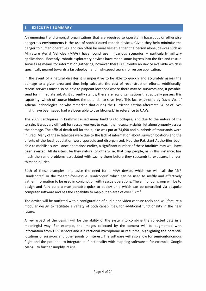
1 EXECUTIVE SUMMARY
An emerging trend amongst organisations that are required to operate in hazardous or otherwise
dangerous environments is the use of sophisticated robotic devices. Given they help minimize the
danger to human operatives, and can often be more versatile than the person alone, devices such as
Miniature Aerial Vehicles (MAVs) have found use in various scenarios – particularly military
applications. Recently, robotic exploratory devices have made some ingress into the fire and rescue
services as means for information gathering; however there is currently no device available which is
specifically geared towards a fast-deployment, high-speed search for rescue application.
In the event of a natural disaster it is imperative to be able to quickly and accurately assess the
damage to a given area and thus help calculate the cost of reconstruction efforts. Additionally,
rescue services must also be able to pinpoint locations where there may be survivors and, if possible,
send for immediate aid. As it currently stands, there are few organisations that actually possess this
capability, which of course hinders the potential to save lives. This fact was noted by David Vos of
Athena Technologies Inc who remarked that during the Hurricane Katrina aftermath "A lot of lives
might have been saved had we been able to use [drones]," in reference to UAVs.
The 2005 Earthquake in Kashmir caused many buildings to collapse, and due to the nature of the
terrain, it was very difficult for rescue workers to reach the necessary sights, let alone properly assess
the damage. The official death toll for the quake was put at 74,698 and hundreds of thousands were
injured. Many of these fatalities were due to the lack of information about survivor locations and the
efforts of the local population were sporadic and disorganised. Had the Pakistani Authorities been
able to mobilise surveillance operations earlier, a significant number of these fatalities may well have
been averted. All disasters, be they natural or otherwise, that trap people, as in this instance, has
much the same problems associated with saving them before they succumb to exposure, hunger,
thirst or injuries.
Both of these examples emphasise the need for a MAV device, which we will call the “SfR
Quadcopter” or the “Search-for-Rescue Quadcopter” which can be used to swiftly and effectively
gather information to be used in conjunction with rescue operations. The aim of our group will be to
design and fully build a man-portable quick to deploy unit, which can be controlled via bespoke
computer software and has the capability to map out an area of over 1 km2.
The device will be outfitted with a configuration of audio and video capture tools and will feature a
modular design to facilitate a variety of both capabilities, for additional functionality in the near
future.
A key aspect of the design will be the ability of the system to combine the collected data in a
meaningful way. For example, the images collected by the camera will be augmented with
information from GPS sensors and a directional microphone in real time, highlighting the potential
locations of survivors and other points of interest. The software will also allow for semi-autonomous
flight and the potential to integrate its functionality with mapping software – for example, Google
Maps – to further simplify its use.

Page 5 of 24
2 MARKET RESEARCH
2.1 SERVICE ROBOTS
2.1.1 MARKET SIZE OF SERVICE ROBOTS
With our group project, the broad market of robotics we will be entering is that of service robots.
According to data from the International Federation of Robotics (IFR) Statistical Department, there
were 63,000 service robots sold for professional use in 20081. Whilst this may appear to be a small
number, ’the total value of total value of professional service robots sold by the end of 2008 was
about US $11billion1, showing there is huge potential in this particular area of robotics.
Figure 1: Service Robots for professional use. Sales up to the end of 2008 and forecast 2009-2012. Source –
World Robotics 2009 2
From the graph it can be seen that by far the largest seller within the service robots category is that
of robots for defence, rescue and security applications. With over 30% of the current market, and
with the forecast for the next few years to bring increasing sales, this sector looks to be particularly
promising. The aim of our group project is to design a product set to capture some of this potential
market value through the use of an Unmanned Aerial Vehicle product.
2.1.2 UNMANNED AERIAL VEHICLES (UAVS)
As their name suggests, UAVs are aircraft that fly without a human crew and are instead controlled
remotely by a pilot some distance away. The earliest UAV was A.M. Low’s ‘Aerial Target’ of 1916, and
since then UAVs have been used for various purposes.
In the 1960s, the US started to develop UAVs designed for spying and reconnaissance. The first such
drone was the ’Firebee’, used over communist China; during the Vietnam War, drones were also

Page 6 of 24
used extensively for exploring war zones. With time, they were equipped with more robust
technology and even missiles for attack purposes. The UAVs currently used by the US in Afghanistan
can fly at an altitude of over 60,000 feet, and are fitted with a variety of sensors.
Although the primary market for UAVs has been the military, they have also found a range of
commercial applications. For instance, they were used during the hurricane attack in Texas and
Louisiana in 2008 for aerial imaging of the disaster area. Photos were taken before and after the
storm hit and processed with imaging software to determine the extent of the damage caused. It is
at this growing commercial market that our project will be aimed. In particular, we will focus on the
sub-category of UAVs known as Miniature Aerial Vehicles.
2.1.3 MINIATURE AERIAL VEHICLES (MAVS)
Miniature (or Micro) Aerial Vehicles are essentially UAVs that are small enough to be man-portable.
Whilst military use is one of the driving factors of development, MAVs are also being used
commercially in scientific and teaching applications, as well as for mapping and security. Another
promising area is remote observation, where drones can be deployed in hazardous environments
that are inaccessible to ground vehicles.
MAVs can come in a number of different configurations ranging from a standard helicopter design to
even insect designs. This of course increases their versatility and the potential for use in various
industries. Furthermore, MAVs, unlike UAVs, are also considerably more appealing to amateur users
who can use them in a manner akin to an RC Helicopter. One such design is the quadcopter which is
one of the most stable and reliable of the MAV designs.
2.2 THE QUADCOPTER
Compared to the saturated RC (Radio Controlled) helicopter market; quadcopters are a relatively
new entry into the UAV/MAV market. Despite this there has been a significant interest from both
hobbyists and researchers into the potential applications that such a machine can offer.
2.2.1 HOBBYISTS
A quick internet search reveals there are a number of topics on hobbyist RC forums dedicated to
quadcopters. These hobbyists can be split into two categories; those who buy ready-made
quadcopters (or RC quadcopters with UAV capabilities already), and those who build quadcopters
from scratch. In both cases custom modifications are often made to improve aspects of the flight of
the quadcopter. However the high entry price of quadcopters, as well as costly components such as
batteries, restricts the hobbyist contingent to a limited number who can afford the necessary
equipment.
2.2.2 RESEARCH
With regards to this project, the work of most significance comes from what researchers are
currently using quadcopter technology for. Unlike traditional RC helicopters, quadcopters generally
offer an easier route to securing flight stability and control, therefore making the area of Miniature
Aerial Vehicles (MAVs) a much more attractive proposition for applications previously unsuitable for

Page 7 of 24
the traditional MAVs. Additionally, given that the cost of
this technology is not such a hindrance to researchers as it
is to hobbyists; various types of quadcopter are currently
under development.
One such application is the use of autonomous flying
quadcopter robots to establish communication networks
in disaster zones. This system currently being developed
at the Ilmenau University of Technology would utilise a
number of quadcopters to create a temporary radio
network for phones and wireless internet.3 Equipped with
GPS, the quadcopters would land after having reached a
suitable location where they could perch to save the very limited battery life.
There are a number of organisations that are currently pursuing commercial applications with
UAV/MAV units. Some of the most prominent are:
1. Aeryon Laboratories (http://www.aeryon.com/) – Aeryon Laboratories' primary product is
the Aeryon Scout unit, which is a man-packable, easy-to-use autonomous hovering aerial
system (UAS) that allows unskilled operators to capture high resolution imagery with a touch
screen interface. It also sells supplementary services for this unit.
2. Cornerstone Research Group (http://www.crgrp.net/micro-air-vehicles.shtml) - CRG’s
Hovering Autonomous Low-profile Observer (HALO) MAV offers capabilities in many
applications, both commercial and military.
3. Ascending Technology (http://asctec.de/main/index.php?id=1&pid=&lang=en&cat=) –
Ascending Technology offers two diverse ranges of multi-rotor models, professional and
hobbyist lines. Both are bespoke, and include a number of surveillance and reconnaissance
capabilities.
4. MAVSTAR (http://cmr.mech.unsw.edu.au/mavstar/index.html) – Founded by Dr Tomonari
Furukawa in late 2006, the project aimed to design and construct of a team of MAVs and
UGVs. To this end they developed a light-weight coaxial helicopter outfitted with a plethora
of video and audio sensors.
The efforts of these organisations have been less focused on UAVs and have been more geared
towards other less traditional designs.
2.2.2.1 SKYBOTIX
Perhaps the most relevant of all research companies in quadcopters
is Skybotix. This company is a spin-off company from the
Autonomous Systems Lab at the Swiss Federal Institute of
Technology, Zurich and since 2003 has been very active in the MAV
research community, developing autonomous quadcoptors, coaxial
helicopters and mini-airplanes. Skybotix provides bespoke MAV
solutions to a high end market for both research and educational
applications.
Figure 2 One of the quadcopters used to
form the wireless network. Source –
Engadget4
Figure 3 The 'CoaX'. Source –
Skybotix5

Page 8 of 24
‘CoaX’ is the name given to Skybotix’s key product – a ready-to-fly robotic coaxial helicopter. It is
largely a generic platform intended to serve a purpose for both research and education. It carries an
embedded computer on board and comes equipped with features including altitude sensors and a
Blutooth module. Optional extras include WiFi functionality, a camera and infra-red sensors.
Skybotix lists the following as potential topics for their product4:
Professional/Research applications
Customs patrol
Avalanche survivor search
Fire surveillance
Natural disaster monitoring
Contamination measurement
Indoor information gathering (police)
Hostile protest control
Road traffic surveillance
Terrain mapping
Aerial photography
Educational applications
Real-time control
Autonomous navigation
Non-linear systems
System linearization
Frequency domain analysis
Estimation theory
Hardware in the loop (HIL)
Multivariable systems control
Dynamics modelling and Identification
2.3 ‘SEARCH FOR RESCUE’ QUADCOPTER
Based on the market research carried out we intend to develop a ”search-for-rescue” quadcopter.
Although our project will be based on the quadcopter, there are many parallels between what
Skybotix do with the CoaX and what we had discussed in group meetings. At the same time, we want
to distinguish ourselves from competitors and ensure that we are unique in our own right.
From the work being carried out by both the Ilmenau University of Technology and Skybotix, it is
readily apparent that there are already existing products geared towards the use of MAVs in rescue
scenarios. The approach taken by Skybotix is to produce a product with a broad range of capabilities,
but not specific to search-for-rescue. The communication networks approach also requires a large
number of quadcopters to be remotely feasible. What is currently not available on the market is a
single quadcopter specifically designed for search-for-rescue applications.
The search-for-rescue quadcopter we aim to design will be an incremental innovation on existing
MAV technology. By using 4 rotors as rather than just one, it benefits from improved stability,
balance and reduced damage to the blades through a reduction of energy in each rotor. It also does
not require mechanical linkages to change the angle of the rotors, leading to a simpler and more
effective design. These properties are clearly advantageous for a search-for-rescue application
where reliability and functionality are crucial.
It is evident that there is appropriate technology to push our product into the market, as well a gap
that it could fill. Although this product is aimed at a relatively small section of the market, there is a
lot of potential value in this niche given the vital role the product could potentially play in emergency
situations. We contacted several businesses who act as the first point of call in the event of
emergencies such as the Ambulance Hazardous Area Response Team (AmbulanceHART), the Red
Page 9 of 24
Cross and the London Fire Brigade. We also contacted other organisations that are also involved
within this process, such as companies that provide audio and surveillance solutions to several of our
target users.
AmbulanceHART remarked that ‘We have looked at this capability or something similar which has
been supplied to the UK Military and a number of Fire Services’ in response to our proposed search-
for-rescue quadcopter. This statement helps us to discern two crucial things. Firstly, it confirms that
there is a genuine need for the product that we are offering, and thus a viable market. Secondly,
knowing that MAVs employed by the UK army (e.g. the T-Hawk MAV) can cost upwards of $250,0005,
we can see that our product can be positioned as a better long-term solution provided it is
comparatively cheaper.
Across both of these organisation types, many people expressed an interest in our concept and it was
described as a ‘truly interesting idea’6 offering unique functionality points, such as audio recognition
as well as the modular design. This meant that the quadcopter could incorporate additional
functionality outside of the default features and be used in a number of different disaster situations
and not just be limited to very remote cases. Based on the feedback we received from these
organisations, we have incorporated some of the key features that were highlighted to us into our
design specification.
3 SPECIFICATIONS AND DEVELOPMENT PLAN
Based on the feedback we received from our market research, we have formulated a set of
specifications that we believe caters to the needs of our potential clients and positions the product
appropriately. This section of the report defines the specifications of the final deliverable and
discusses the stages of development.
3.1 SPECIFICATIONS
The specifications can be split into 6 different sections: Mechanical Design, Data Acquisition,
Processing, Communication, Control and Powering. The actual functioning of these will be discussed
in more detail in the High Level Design.
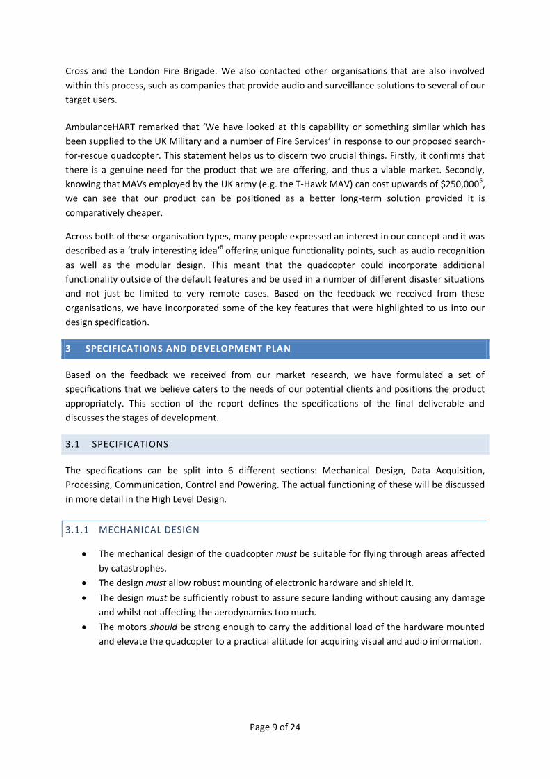
3.1.1 MECHANICAL DESIGN
The mechanical design of the quadcopter must be suitable for flying through areas affected
by catastrophes.
The design must allow robust mounting of electronic hardware and shield it.
The design must be sufficiently robust to assure secure landing without causing any damage
and whilst not affecting the aerodynamics too much.
The motors should be strong enough to carry the additional load of the hardware mounted
and elevate the quadcopter to a practical altitude for acquiring visual and audio information.

Page 10 of 24
3.1.2 DATA ACQUISITION
The quadcopter must capture visual data in the form of videos and images of the
catastrophe-affected area.
The videos and images must provide information on the scale of the catastrophe.
The device must record audio data.
The audio data must assist in locating victims.
3.1.3 PROCESSING
The device must store all data on a memory device, which can later be read by the operator
after the quadcopter returns to base.
The processing on board must be sufficiently quick and efficient in order to manipulate visual
data and execute control instructions in real time.
3.1.4 COMMUNICATION
The device must receive instructions from the base and carry them out.
The quadcopter should transmit visual and audible information to the base.
The transmission of data should be implemented in real time, permitting a spontaneous
analysis of the scale of the catastrophe.
3.1.5 CONTROL
A software application-based control system must be implemented. This application will
enable the user to steer the quadcopter manually and program routes the device should
follow.
An on-board control system must be implemented to smoothen out flight in order to reduce
perturbations from the desired flying route.
An on-board control system should be employed to enable the quadcopter to fly back to the
base autonomously in case of an emergency such as low battery.
The Device should be equipped with sensors that allow the quadcopter to avoid collisions.
3.1.6 POWER
The power system must have a sufficient capacity to power the quadcopter to fly to the
catastrophe hit area, transmit pictures and videos, communicate with the base and return to
the base.
4 HIGH LEVEL DESIGN
4.1 INITIAL HELICOPTER DESIGN
Since we are manufacturing the helicopter from a pre-designed kit, modifications will be required to
ensure that it conforms to our specifications. A standard, unmodified remote controlled helicopter
kit functions as follows:

Page 11 of 24
Figure 4: Helicopter kit design
Several aspects of this design are insufficient. The radio link is inadequate in two ways: firstly, it is
suitable only for carrying simple control commands (e.g. “up”, “down”, “left” etc.); secondly, it
carries data in only one direction. In order to transmit complex commands and receive data back in
response, a higher-speed bidirectional radio system is necessary.
4.2 CUSTOM DESIGN
Our design is split into three principal components: the helicopter instrumentation; a custom-built
software package; and the radio communication system that links the two. These are divided
between two physical devices: a ‘base station’ PC, and the helicopter itself.
Figure 5: Proposed quadcopter system design
The instrumentation on the helicopter consists of a number of components, including a GPS module,
a video camera and a fixed high-resolution digital camera. These devices will be under the full control
of the CPU, which will be capable of encoding the data and either transmitting it back to the base
station through the radio link or storing it locally for later retrieval. The CPU will also be capable of
executing commands based on this data (for example, flying through a series of GPS waypoints).
The software control system loaded onto the base station will act as the sole source of control for
the helicopter. It will have the capacity to create flight programs, which will be transmitted to the
helicopter. The ability to override autonomous flight and manually control the helicopter will also be
included.
A key principle that we will keep in mind throughout the entire design process will be that of
modularity. Although our system is tailored towards a specific application, the general platform (i.e.
the quadcopter and the software) has a much broader range of potential applications. Ensuring that
Remote
control Radio control
Receiver Control
system Motors
Software control system
Radio data link
Receiver CPU
Control system & motors
Instrumentation
Local storage
Page 12 of 24
the design is easily modified will allow specialized units for other applications to be created in the
future.
4.2.1 COMMUNICATION SYSTEM
The communication system is one of the most important elements of the design. The restriction it
places on the amount of data that can be transmitted shapes the specifications of all of the data-
generating blocks, and particularly the cameras.
Our plan is to completely replace the existing wireless control link with one capable of transmitting
complex instructions, which will then by executed by a CPU on board the helicopter. Moreover, it will
be bidirectional, allowing for the transmission of images and video from the helicopter back to the
base station.
We have chosen to use a pre-built communication system for two reasons. Firstly, the time and cost
of designing and building a custom wireless link capable of meeting our specifications would almost
certainly exceed our budget. Secondly, there would be no guarantee that we could obtain sufficient
performance from our specifications. With a pre-designed communication system with well-defined
specifications, these problems are all but eliminated.
4.2.1.1 WIRELESS LAN (WLAN)
A wireless LAN is designed to allow computers in close proximity to communicate, sharing an
internet connection or files. If we choose to implement this, we can consider the base station to be a
router which sends data to the wirelessly-enabled helicopter. This is a standard topology.
Wi-Fi, as used widely in modern households and workplaces, has a data rate sufficient for our
purposes but is optimized for situations in which the transceivers are stationary. This renders it
unsuitable for our project on performance grounds.
A newer development in wireless networking is WiMAX, which comes in many varieties, ranging from
IEEE 802.16d to 802.16e. The ‘e’ variant, in addition to having the required throughput, was designed
with mobility in mind, making it ideal for our application.7
4.2.2 IMAGE CAPTURE
The helicopter is required to capture two different types of image. The first is a live video feed, which
will be used to assist manual control of the helicopter and give the operator a more intuitive means
of gauging the helicopter’s position. The second is a high-resolution digital camera used to capture
images of the disaster zone.
Although we could potentially construct our own cameras with a custom combination of sensors,
lens holders and lenses, this would add significant development time and cost. It is for this reason
that we have chosen to use pre-assembled commercial units.
Both cameras will be natively digital to avoid the additional complexity of an analogue-to-digital
converter. In keeping with our modular design ethic, the cameras will also be mounted on their own

Page 13 of 24
dedicated daughterboards. This will allow easy future replacement if we wish to upgrade them or
replace a faulty component.
4.2.2.1 VIDEO CAMERA
Because the video camera will be streaming live data, we will have to trade off the resolution and
FPS (frames per second) of the camera against the bandwidth required to transmit its data. However,
because the video camera exists only to provide rough navigational and orientation information,
bandwidth can be conserved by selecting a lower resolution model.
Digital video cameras are available in resolutions ranging from full High Definition (1280x720) to as
low as 172x60. The optimum resolution for our needs is around the 640x480 mark (VGA), which,
when combined with suitable image compression (discussed later), will not occupy excessive
bandwidth.
For smooth, full-motion video, a speed of above 25 fps will be required. However, this will create
large amounts of data, reducing the speed available to transmit the high resolution fixed camera
images. Since the video camera is only required for rough navigation, a more feasible option would
be to use a camera capable of taking pictures at 5-15 fps and transmit these images sequentially. This
would also significantly reduce the cost.
4.2.2.2 FIXED CAMERA
A similar trade-off exists with the fixed camera. However, although the resolution will be much
higher, the information does not need to be delivered in real time. In this case it makes sense to
select a relatively high resolution to maximize the chance of spotting crucial details.
The optimum resolution for our application can be calculated by requiring that the helicopter be able
to spot a human-sized object from a maximum flying height of 30 feet (9.14m). To investigate this
requirement, a small experiment was designed to evaluate object visibility with images of varying
resolution. Identical images were taken at camera resolutions of 1MP, 2MP, 3MP & 5MP with
consumer cameras. We found that a suitably sized object 80m away was readily visible at resolutions
as low as 2MP, suggesting that this is the minimum acceptable rating for our fixed camera. Rough
calculations show that from a height of 9.14m, the camera can image an area of just under 70m2.
4.2.3 IMAGE PROCESSING
The processing of the images can be divided into two parts: the compression of the images for
storage and transmission, and the post-processing tasks that take place at the base station.
4.2.3.1 IMAGE COMPRESSION
Compression of the images is key to allowing us to transmit them wirelessly and store them
efficiently. However, compression algorithms tend to be optimized for specific situations – for
example, motion video – and so to maximize the efficiency of the system we may have to employ
different compressors for the still image and video data.
Page 14 of 24
For the video processing, there are two feasible options. H.264, a video codec designed with slow-
moving images in mind, achieves excellent compression ratios (up to 60:1)8 and is ideally suited for
the video that we will be transmitting. However, it is computationally very expensive which, given
the limited processing power available on board, would require the use of a separate encoder chip.
This adds a large amount of unwanted complexity to our design.
The second option is the JPEG codec, which is optimized for still images. The compression ratio, while
inferior to that of H.264, is respectable – it should be able to compress a 640x480 image down to less
than 50 kilobytes. This will allow us to send 10 images per second, which is line with the desired
camera FPS. Moreover, the algorithm is much less computationally expensive than H.264. JPEG
compression routines are simple enough to run on a standard ARM processor9 which would translate
into a substantial reduction in complexity. An additional advantage of the JPEG algorithm is that the
same routines could be used for both the video and fixed images, reducing the amount of code
required at both the base station and helicopter.
Given the limited time and money available, for this pilot project it seems appropriate to opt for
simplicity of design over very high efficiency, especially given that the compression performance of
the JPEG algorithm is more than adequate. It therefore makes sense to use JPEG encoding for both
the still and “video” images.
4.2.3.2 POST-PROCESSING
Once the images have been received by the base station – whether wirelessly or via the storage card
– they need to be processed to display the useful information.
The video images, while useful for navigation or investigating things in real time, do not include any
information that could not be gained from the high-resolution photographs. The frames will be
stored as a flight record, but not processed in any way.
The processing of the fixed camera images can be broadly divided into two stages. Firstly, the images
must be “stitched” together to form a coherent picture. This would then be overlaid onto a map of
the area which could be panned and zoomed to focus on particular areas. Secondly, the images
would need to be augmented with the additional data collected during the flight. For example,
regions where audio profiles matching human speech are detected could be flagged on the map for
further investigation. The user should also be able to request the GPS coordinates of any point on the
images in order to direct ground rescuers to that particular area.
4.2.4 SOFTWARE CONTROL / ANALYSIS SYSTEM
The software is the only means by which the end user will be able to control the helicopter. It is
therefore essential that it be user-friendly and present the required information in an easy to
understand format. In order to achieve this, the design must be highly visually oriented.
A rough sketch of the software’s interface is presented below:

Page 15 of 24
Figure 6: Rough layout of software interface
The design is focused around the use of the map (right), where the locations of the helicopter and
base station are displayed. It will also serve as an area to overlay the high resolution fixed camera
images. Shown is a polygon created from a series of GPS waypoints, which can be added to the map
by simply clicking at the desired location. Given this series of waypoints, the software can transmit a
range of preset commands to the helicopter – for example, to photograph the area in a grid pattern,
or to patrol its perimeter.
Although these simple functions will be easily selectable with buttons, the software will in fact be
generating a series of underlying commands to be sent to, and executed by, the helicopter. These
commands will be a custom scripting language, meaning that the helicopter could in theory be
programmed manually. This functionality, while not directly applicable to the “search for rescue”
application, will allow easy future customisation. New behaviours could easily be added to the
helicopter to suit specific applications.
Visible on the left of the design is the video feed from the helicopter, along with speed and height
information. This portion of the “control panel” will also have a override so that the operator can
control the helicopter if they wish.

Page 16 of 24
4.2.5 POWER
Our specifications require that the power system have sufficient capacity to allow the quadcopter to
fly to the catastrophe area, acquire and transmit pictures, videos and audio data and then return to
the base station. This process is expected to take approximately 20 minutes. To provide a suitable
safety margin, the battery should ideally last for at least 30 minutes.
The most power will be consumed by the four motors, the processor and the wireless module:
Component Typical power consumption
Motors ~ 430W10*
Processor ~ 1W (maximum)
Camera ~ 800mW11
Radio system ~ 3W
Audio amp. < 100mW
Table 1: Typical power consumption of various components†
However, the power consumption of the added components is insignificant compared to that
consumed by the motors. Since the basic quadcopter kit will have sufficient capacity to power the
motors, the additional equipment should not significantly impact battery life.
4.2.6 MICROPHONE
The microphone has to exhibit a high enough sensitivity in order to be able to record data which lies
within the frequency ranges of human speech. This will be problematic, as there is expected to be a
lot of added noise from the motors, wind and vibrations. High order filters will be implemented in
software in order to filter out only the frequency range of interest. Moreover the microphone should
exhibit a high directivity in order to be able to locate victims.
4.2.7 STORAGE
Our specifications state that the quadcopter must store all data on a memory device. This storage
device should be compatible with the processor used in order to reduce time delays. With ARM7
processor flash memory device could be used.
For estimating the storage capacity required we assume that the time travelled in the catastrophe
affected area will be at most 20 minutes. Most of the data stored during this time can be accounted
for by the video and audio stream and high resolution pictures.
Type of Data Sampling frequency Size of data item Size required
JPEG images 2 images/min 2 megabytes/image ~80MB Audio recordings 30 kHz 8 bits/sample ~35MB Video recordings 10 frames/second 50 kilobytes/frame ~600MB GPS & misc 1 Hz negligible ~1MB
Total: ~716MB
Table 2: Storage capacities required for various data items
* Based on 60% utilisation
† Components with negligible power consumption omitted

Page 17 of 24
The flash storage capacity should be therefore be around 1GB. SD cards will be used for onboard
data storage. The SD cards are relatively cheap and will allow for later expansion of the storage
capacity.
5 DEVELOPMENT PLAN
The previous section has described how the specifications defined are going to be achieved. In order
to realize this design, a development plan in form of a “stage gate process” has to be laid out by
outlining the targets and tests that have to be completed.
The development of the device can be achieved by splitting the work load into three sections:
Instrumentation and Control, Communication and Windows Application. These three sections are
fairly independent, but often require collaboration with others. In order to build the target as quickly
as possible it is necessary that these three sections work in parallel where possible. Once the “sub-
targets” in each of the fields are realized, the work can be integrated to create the final deliverable.
The diagram illustrates the three sections and the 4 stages planned. A detailed explanation of the
diagram is given in the following paragraphs:
Figure 7: Development stages
5.1.1.1 STAGE 1
In stage 1 the first task for the Instrumentation and Control Team is the “Control System Design”.
This includes installing the accelerometers and programming microprocessors in order to implement
a functioning control system, which reduces perturbations from the desired flying route.
Communication
Implement
Communication
System
Data Transmission
Windows Application N/A Basic Computer
Control
Instrumentation
and Control
Data
Acquisition
Hardware
Control System
Design
N/A
N/A
Advanced
Computer
Control
1
2
3 Stage
Page 18 of 24
At the same time the Communications team need to “Implement the Communication System”. This
involves hacking the manual control remote and making it possible to communicate with the
quadcopter from the computer.
5.1.1.2 STAGE 2
Following Stage 1 the Instrumentation and Control Team will install the “Data Acquisition Hardware”.
This includes cameras, microphones and the GPS module. It is the team’s responsibility to program
the processors to carry out the processing of the information acquired by the hardware, such that it
is ready to be transmitted.
The task “Data Transmission” is then carried out by the Communications Team. They have to make
sure that the data is being transmitted promptly and efficiently and received by the computer.
Simultaneously, the Windows Application Team will write software that enables “Basic Computer
Control” for the user. This control mechanism works just the same way as the manual remote
control, the only difference being that the commands are sent from a computer via a different
communication system, set up in Stage 1.
5.1.1.3 STAGE 3
Finally the Windows Application team expands the Program in order to implement “Advanced
Computer Control”. As discussed in the High Level Design, this Application will enable the user to use
a map which shows locations the quadcopter should fly to and send preset commands.
6 MANAGEMENT PLAN
This project has a large scope in terms of development. We believe that careful time management
and contingency plans are essential.
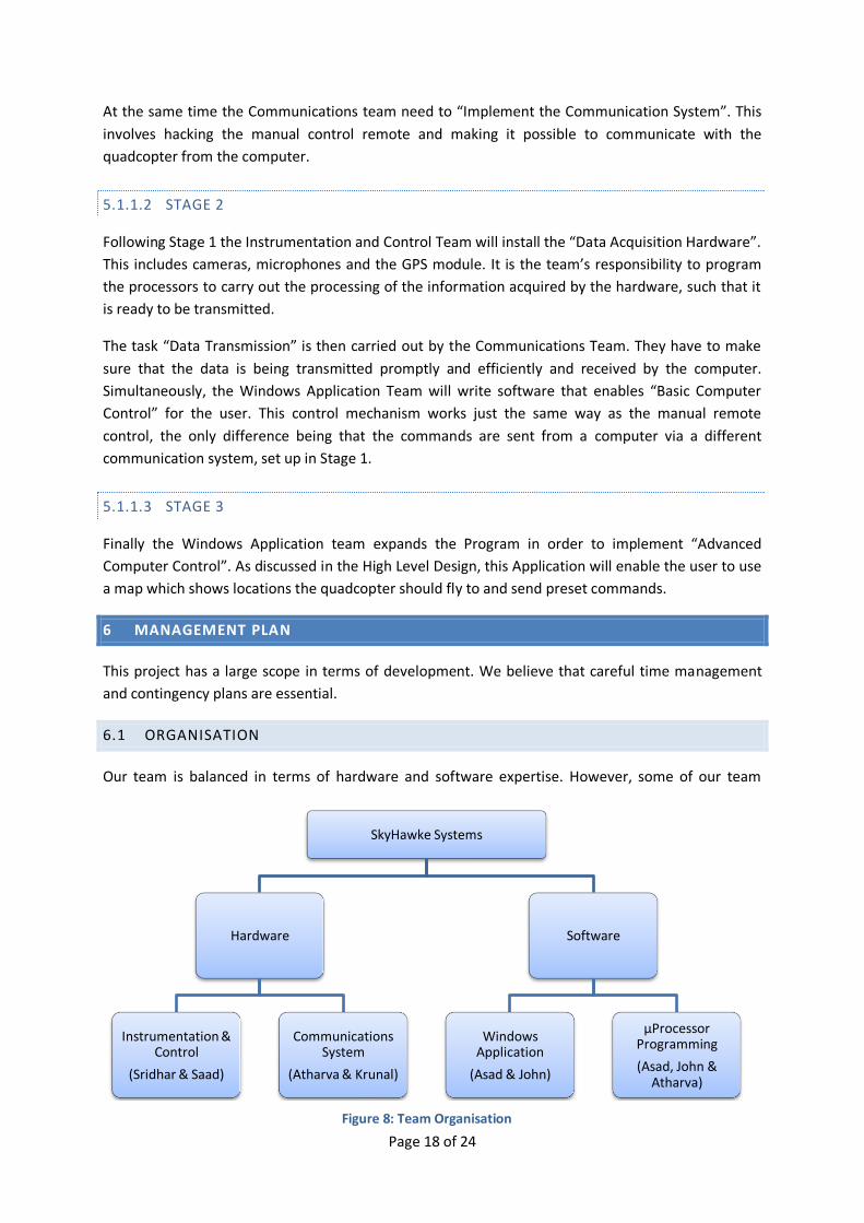
6.1 ORGANISATION
Our team is balanced in terms of hardware and software expertise. However, some of our team
SkyHawke Systems
Hardware
Instrumentation & Control
(Sridhar & Saad)
Communications System
(Atharva & Krunal)
Software
Windows Application
(Asad & John)
µProcessor Programming
(Asad, John & Atharva)
Figure 8: Team Organisation
Page 19 of 24
members are also experienced in marketing and business sectors. The above diagram shows the task
allocations according to individual strengths.
6.2 TIME MANAGEMENT
As the current stage of the project, it is decided to split the project into 3 stages corresponding to
each term. Please refer to the Gantt chart in section 8 (Appendix 2) of this report for detailed time
plan. During the summer term only 3-4 weeks are available for the build phase. We believe this is a
short time to implement all the desired features and thus have split the specification section into
must and should have sections.
6.3 BUDGET
The stated budget for this project is £300. However, during research it was found that some of the
basic kit required for this project itself is approximately £300. In this case, the course coordinator will
be consulted to find out the feasibility of buying the kit outside of budget. Since the kit is reusable for
successive groups it should be economical for the department to buy the kit.
If the quadcopter kit is bought by the department then the budget will be spent on components such
as Cameras, any mounts for the camera, wireless transmitters and receivers, GPS module. The
approximate costs total £200‡. To develop Microsoft Windows application, SDKs§ are necessary.
However the costs can be discounted as the department has volume licenses for these software
packages.
6.4 CONTINGENCY PLANS
The wide scope of the project means that we have to consider Murphy ’s Law: “If anything can go
wrong, it will”.12 Thus in such situations where a part of the project cannot be completed due to
defects with a module, secondary plans need to be in place.
It should be noted from the specifications section that some of the details have been noted as
'should'. Most of this functionality will be implemented if there is sufficient time available after
implementing all the ‘must’ have features.
6.4.1 DATA COMMUNICATIONS SYSTEM
The proposed system for use is Wi-Fi IEEE 802.11. This is an established yet complex solution to
implement. Alternatives** such as 2.4GHz IEEE 802.15 and Bluetooth (2450MHz) are available for
hobbyist use which suggests ease of application. However, if it is not possible to implement these
wireless technologies due to time constraints (or otherwise) the plan is to3 rely solely on the
onboard memory to capture the required data.
‡ Costs totalled after considering range of products.
§ SDK – Software Development Kit
** List of technologies not exhaustive
Figure 4: Project plan

Page 20 of 24
7 APPENDIX 1: MEETING MINUTES
7.1 29TH OCTOBER 2009
Team Members present: John, Atharva, Krunal, Saad, Asad, and Sridhar (none absent, none late)
The aim of this meeting was to get all members together to briefly think about technically and
financially feasible applications of computer controlled helicopters.
Applications of computer controlled helicopters
o Security patrol
A mounted camera on a helicopter which patrols in an area and sends the
video data in real time to a computer for security.
After consideration of battery life we concluded that this application is not
feasible, because the battery would have to be recharged every 30 minutes.
o Aerial photography
A mounted camera on a helicopter which can be used to take high resolution
pictures of building or areas.
o Educational
Control system of the helicopter can be used to demonstrate concepts in
control theory to students.
7.2 9TH NOVEMBER 2009
Team Members present: John, Atharva, Krunal, Saad, Asad, and Sridhar (none absent, none late)
Helicopter kits
o We decided to use a quadcopter instead of a helicopter. These have the advantage,
that they can be controlled much easier.
Applications of computer controlled helicopters
o Mine detection
Quadcopter flies close to the ground with a mounted camera. Camera and
shape detection algorithm can be used for detecting mines on the ground.
o Search-for-rescue
Mounted cameras on the quadcopter can be used to gather information
about the scale of a catastrophe, by flying the Quadcopter to the catastrophe
hit area.
A thermal imaging camera can be used to simplify the search for people.
Meeting with Professor Richard Syms (Semiconductor and Optics Group) to discuss thermal
imaging cameras
o Found not to be financially or technically feasible.

Page 21 of 24
7.3 16TH NOVEMBER 2009
Team Members present: John, Atharva, Krunal, Saad, Asad, and Sridhar (none absent, none late)
After consideration of all ideas for applications, search-for-rescue was selected as the
application.
Specification of the applications
o Quadcopter is controlled by a computer.
o Data obtained by camera on the quadcopter is sent via wireless link
Identification of technical workload for the project
o Control and Instrumentation
o Communication System
o Software
Distribution of work in inception report
o Market Research
Krunal, Asad, Saad
o Specifications
Sridhar
o High Level Design
John, Atharva
o Development Plan
Sridhar
o Management Report
Atharva
o Executive Summary
Asad
7.4 23RD NOVEMBER 2009
Team Members present: John, Atharva, Krunal, Saad, Asad, and Sridhar (none absent, none late)
Meeting with project supervisor, Liam Madden
o Since several similar projects already exist in the market we need to incorporate
more ideas in order to differentiate the product.
The use of a directional microphone and filters that filter only the frequency
range of human speech could assist in locating people.
A GPS module that is installed can be used to send the coordinates of
locations where people might be found.
The Software on the computer can be programme for more advanced control: instead of
having to steer the quadcopter manually, we could program macros which simplify the
control of the quadcopter. For example, coordinates of locations the quadcopter should visit
can be sent to the device such that it automatically flies there.

Page 22 of 24
8 APPENDIX 2: GANTT CHART

Page 23 of 24
Page 24 of 24
9 REFERENCES
1 World Robotics, IFR Press Statement, 30th September 2009, Available from: http://www.worldrobotics.org/downloads/PR_Service_Robots_30_09_2009_EN.pdf [Accessed 24/11/09] 2 World Robotics, IFR Charts, 30th September 2009, Available from: http://www.worldrobotics.org/downloads/Charts_30_09_2009(1).pdf [Accessed 24/11/09] 3 Engadget, Researchers develop flying WiFi robots for disaster relief, 4th March 2009, Available from: http://www.engadget.com/2009/03/04/researchers-develop-flying-wifi-robots-for-disaster-relief/ [Accessed 24/11/09] 4 Skybotix, Skybotix Home Page, undated http://www.skybotix.com/ [Accessed 24/11/09] 5BBC News Online, Robot planes take to the skies, 12th March 2009. Available from: http://news.bbc.co.uk/1/hi/technology/7938522.stm [Accessed 25/11/09] 6 Ashley Beard, Sales and Marketing at Thomas Jacks Limited 7 Research and Markets, Communications for High-Speed Moving Objects: IEEE 802.16e, IEEE 802.20 and 5.9 GHz DSRC, February 2007. Available from: http://www.researchandmarkets.com/reports/445820 [Accessed 27/11/09] 8 Kane Computing Ltd, Compression Ratios: Rules of Thumb, undated. Available from: http://www.kanecomputing.co.uk/pdfs/compression_ratio_rules_of_thumb.pdf [Accessed 23/11/09] 9 ITG, JPEG Compression Utilities, 6th August 1995. Available at http://dir.filewatcher.com/d/OpenBSD/3.5/arm/jpeg-6b.tgz.210281.html [Accessed 29/11/09] 10 HobbyKing Online R/C Store Catalogue, November 2009. Available at: http://www.hobbycity.com/hobbycity/store/uh_viewItem.asp?idProduct=5499 [Accessed 30/11/09] 11 4D Systems Online Catalogue, November 2009. Available at: http://www.4dsystems.com.au/prod.php?id=76 [Accessed 30/11/09] 12 Commonly known definition taken from http://www.murphys-laws.com/murphy/murphy-laws.html


![Volta Inception Workshop Final Report[1]](https://static.fdocuments.in/doc/165x107/577d26741a28ab4e1ea142a9/volta-inception-workshop-final-report1.jpg)