
In Verna Dero
21
Q -.
Transcript of In Verna Dero

Q
-.

Division of Agricultural Sciences
REPRINTED OCTOBER 1980
LEAFLET
2387

The author is James F. Thompson, Extension Agricultural Engineer, Davis.
The University of California Cooperative Extension in compliance with the Civil Rights Act of 1964, Title IX of the Education Amendments of 1972, and the Rehabilitation Act of 1973 does not discriminate on the basis of race, creed, religion, color, national origin, sex, or mental or physical handicap in any of its programs or activities. Inquiries regarding this policy may be directed to: Affirmative Action Officer, Cooperative Extension, 317 University Hall,
University of California, Berkeley, California 94720, (415) 642-0931.
Issued in furtherance of Cooperative Extension work, Acts of May 8 and June 30, 1914, in cooperation with the United States Department of Agriculture, James 8. Kendrick, Jr., Director, Cooperative Extension, University of California.
4m-10/80-DCK/LAM

Many home gardeners find a small greenhouse a
relaxi:tg hobby as well as very useful. It can be
used to root cuttings andsminate seeds for the
outdoor garden, special flowers or ornamental5 can
be raised, and vegetables can be grown out of
season. A carefully chosen and attractive green-
house can provide many hours of enjoyment. How-
ever, before building one, be sure to consider:
e location
e type of construction
e heating and ventilating
e maintenance
LOCATION
A sunny location is best. Locate the house as far
from trees as practical. A southern or southeastern
exposure is best for maximum light during the
winter.
The greenhouse should be convenient to water,
fuel for heating, and electricity. The area should
be well drained.
TYPES OF GREENHOUSES
Almost everyone can find a greenhouse style to
suit his needs. There is a bewildering variety of
sizes, shapes, and styles. Greenhouses range from
window-box size to 20 or 30 feet wide and 100 or
inore feet long. The size you choose depends on
the area available, how much greenhouse garden-
ing you wish to do, and the cost.
Gothic arch, rigid frame, air supported, shed roof,
and conventional pitched roof are just a few of
the available shapes. A greenhouse that fits both
existing landscape and personal preference dic- tates the choice. Greenhouses are made with glass, fiberglass, polyethylene, or vinyl cov-
erings. Wood, steel, and aluminum are used for framing.
Glass
Glass houses are very attractive, permanent, and
expensive. These houses should be built by a
greenhouse manufacturer or purchased in a ready-
to-assemble package because they are difficult
to construct. Any gardening magazine advertises
companies selling these houses.
Fiberglass
Houses covered with fiberglass are durable, at-
tractive, and moderately priced. They are com-
mercially available or can be designed and built
by the home handyman. Only transpurent or trans-
lucent fiberglass weighing 4 to 5 ounces per
square foot should be used. Most manufacturers
sell a fiberglass made for greenhouses and it
should be guaranteed for 10 to 20 years. Except
for shading, lower grades and colored panels
should be avoided.
Film Plastic
Film-plastic-covered greenhouses are inexpensive
and temporary. They are less attractive and require
more maintenance than other styles. Clear poly-
ethylene, 4 or 6 mils (0.004 to 0.006 inch) thick,
is most commonly used because it is inexpensive
and readily available. Unfortunately polyethylene
only lasts from 3 to 8 months because it is rapidly
broken down by ultraviolet radiation from the sun.
Polyethylene treated with an ultraviolet (UV) in-
hibitor is slightly more expensive but will last 3
to 6 months longer than the regular polyethylene.
This film should be used if the greenhouse is to
be covered in the summer or fall.
Longer lasting film plastics are available, but
they have other disadvantages besides being more
expensive. If more permanence is desired, the
house can be covered with fiberglass. Polyethyl-
ene film costs 2 to 3 cents per square foot, fiber-
glass, 40 to 60 cents per square foot.
1

GREENHOUSE CONSTRUCTION HEATING
Types of Heaters
Th e greenhouse must be heated for winter use.
Mony types of heating systems are available.
Use seasoned, construction-grade lumber when
building the greenhouses described here. Redwood
or Douglas-fir is best.
Paint the framework with a white exterior paint to
improve appearance and reflect more light.
Posts and wood that touch the ground should be
treated with copper naphthenate preservative. Do
not use creosote and pentachorophenol preserva-
tives because they releasevapors harmful to plants.
Polyethylene film should be installed on calm
days. Film plastic first tears at the places where
it touches the greenhouse frame or where it is
folded. Wide,unfolded sheets of plastic are avail-
able anr! should be used. A batten strip at least
as wide as the rafter will help extend film life.
Double headed nails are often used to fasten the
plastic since they are easier to remove.
Two layers of plastic can be installed to reduce
heat loss as much as 40 percent and eliminate
condensation on the p!astic. An inside layer of
plastic 2 to 4 mils thick is spaced 1 to 4 inches
from the outside layer to create a dead airspace.
Closer or wider spacing does not create an effec-
tive dead airspace.
Although two layers are difficult to install, they
are well worth the trouble. Typically, both layers
can be installed on the outside of the framework
with a 2x2 spacer placed between the lrlyers
where they are fastened to the rafters. One sheet
is held by the 2x2 nailed just to hold it in place.
The second sheet can then be held with the batten
strip and nails driven through the 2 x2 and an inch
or more into the rafter.
In small greenhouses, the inner layer of plastic
can be fastened to the inside framework with
staples driven over a string. Simply pulling the
string removes the staples.
Home Heating Systems. If a home heater’s ca-
pacity is adequate, it can be extended to a small
nearby greenhouse. However, the heat demand is
dffforent than that of the home so a separate ther-
mostat and control system are required. A heating
contractor normallywill be needed for installation.
Space-Heaters. Either electric, gas, or oil space-
heaters nre often used to heat small greenhouses.
Heated air is circulated by a fan in the heater.
Some space-heaters have no fan and so are rather
uneven and ineffective. Depending on the size of
unit, space-heaters should not be more than 10 to
30 feet apart to produce uniform heating.
Oil or gas heaters must be vented to the outside
since the products of combustion are toxic to
plants. Electric he t a ers are easier to install and
are convenient but cost more to operate than gas
heaters.
Space-Heaters With Ducts. Recently a heating
system has been devised to distribute heat more
uniformly through the greenhouse. A space-heater
with a fan built for moving air in ducts is attached
to a clear polyethylene tube (diameter, 12” to 24”)
hung overhead. The tube has 2- to 3-inch holes
punched along it every 2 or 3 feet. Warmed air is
biown into the tube and out the small holes to pro-
vide uniform heating. When no heat is needed, the
furnace can be shut off and the fan left on to ven-
ti late the greenhouse. The fan-heater unit is lo-
cated near the end of the greenhouse so outside
airwill be drawn througha door oropening into the
fan and tube to be blown throughout the greenhouse.
Usually this equipment is not needed for small
greenhouses because space-heaters alone are
satisfactory and less expensive. Normally, green-
houses are at least 15 to 20 feet wide and 50 to
100 feet long before this equipment is used.
2
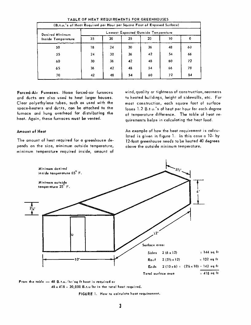
TABLE OF HEAT REQUIREMENTS FOR GREENHOUSES
I (13.t.u. ‘s of Heat Required per Hour per Square Foot of Exposed Surface) 1
55
60
65
1 70
35
18
24
30
36
42
Lowest Exoected Outside Tern oe
30 25 20
ra tu re
10 0
24 30 36 48 60
30 36 42 54 66
36 42 48 60 72
42 48 54 66 78
48 54 60 72 a4
Forced-Air Furnaces. Home forced-air furnaces wind,quality or tightness of construction, nearness
and ducts are also used to heat larger houses. to heated buildings, height of sidewalls, etc. For
Clear polyethylene tubes, such as used with the most construction, each square foot of surface space-heaters and ducts, can be attached to the loses 1.2 B.t.u.‘s of heat per hour for each degree furnace and hung overhead for distributing the
heat. Again, these furnaces must be vented. of temperature difference. The table of heat re-
quirements helps in calculating the heat load.
Amount of Heat
The amount of heat required for a greenhouse de-
pends on the size, minimum outside temperature,
minimum temperature required inside, amount of
1
An example of how the heat requirement is calcu-
lated is given in figure 1. In this case a lo- by
12-foot greenhouse needs to be heated 40 degrees
above the outside minimum temperature.
Minimum desired
inside temperature 65’ F.
Minimum outside n temperature 2!5- F. temperature 2!5- F. t t
6' 6'
I I
-I.- -I.-
= 144 sq ft = 144 sq ft
= 132 sq ft = 132 sq ft
Ends Ends 2(10x6)+ (2%x10) q 142 sqft 2(10x6)+ (2%x10) q 142 sqft
Total surface area Total surface area = 418 sq ft = 418 sq ft
From the table - 48 B.t.u.ihr/sq it heat is required or
48x 418 = 20,000 B.t.u/hr is the total heat required.
FIGURE 1. How to calculate heat requirement.
3

Gas or oil heaters are frequently rated according
to the total heat input. Some heat escapes through
in:; vent so the usable heat is only about 70 per-
cent of this total. If a gas heater were used in ,the
greenhouse shown in the example, it should have
a heat input rating of about
20,000 p = 28,600 B.t.u./hr
0.70
If two layers of plastic are used, the heat loss is
about 70 percentof the loss through a single layer
of plastic. If the house in the example is built
with a double layer of plastic, the heat require-
ment would then be 20,000 x0.70 = 14,000 B.t.u./
hr. Of course, if a gas heater were used with the
double plastic, its heat input would be
14,000
0.70 = 20,000 B.t.u./hr
Maintenance and Safety
Choose heaters having o safety switch or safety
pi lot. Be sure gas heaters are vented.
Clean dust from the burners and ducts before
starting heating in the fall.
Check the flame to be sure it is burning with a
clear blue color. A yellow flame indicates in-
complete combustion and theflame setting should
be corrected.
Be sure the thermostot is protected from rain and
is operating.
For greater heater efficiency keep the greenhouse
doors closed and patch all holes.
VENTILATION AND COOLING
Greenhouses must have air movement for cooling.
In winter, air movement is needed to reduce ex-
cess humidity, condensation, and dripping of
moisture from the roof. Either greenhouse vents
or fons can be used.
Vents. A continuous vent at the top or ridge of
the greenhouse, combined with vents on the sides,
gives the most effective naturol ventilation. For
smal I greenhouses, a 1- to 2-foot wide vent i s
adequate. In larger greenhouses, a ridge vent
I,, the width of the house should be used. For
example, if a house is 24 feet wide, at least a
3-foot-wide (‘,x 24) ridge vent should be used.
Side vents are often not used in houses less than
15 feet long, since an open door or o few holes
at each end allows enough air to enter on hot
days. For very small houses, like those on plans
5941 and 5946, smaller ridge vents, open doors,
or end vents provide enough ventilation.
Ridge vents should be opened slightly in cold
weather to allow some moisture-laden air to
escape. With noventilation, humidity in the green-
house becomes too high and condensation, drip,
and dicey?e become severe problems.
Circulating Fans. Sometimes small fans are used
to circulate air within the greenhouse to try to
eliminote stagnant air pockets. Thesefans should
only be used to correct a poorly designed heating
and ventilating system. In small greenhouses end
in greenhouses with good heating and ventilation
systems, they are not of much use.
Cooling Fans. More positive air control is needed
if the greenhouse is used in the summer. Fans
will ventilate even on a calm, hot, summer day.
Also, fans are easier to control automatically than
vents. However, fans are more expensive and not
normally used except in large houses. The fan
exhausts the air from the house, and during warm
weather it should change the air once every
minute.
Cooling Pads. In large houses, a wetted aspen-
fiber pad can be placed at one end and fans at the
other to provide additional cooling. As the air is
drawn through the wet pad it is cooled by evapo-
ration-as much as 30 degrees on hot days. If
additional cooling is needed in small greenhouses,
a package evaporative cooler is more satisfactory.
The cooler can be mounted to blow cool air into
the house at one end and the door opened on the
opposite end to exhaust the air. Coolers should
change the air once per minute. The volume of
of the house shown in the heating example is 855
cubic feet -the amount of air a cooler for this
house would need to deliver per minute.
4

Shading. Shades, of course, besides reducing
light, reduce the heat load in greenhouses. Shad-
ing compounds that are sprayed or painted on the
greenhouse and aluminum, fibergiass, plastic, or
wooden screens and panels are avai lable. Partial
shading does not normally reduce summer light
enough to reduce growth, but it is a good way to
reduce the heat load.
Humidification. During hot days the humidity in
a greenhouse can become so low that plants are
severely dehydrated and even ruined. Moreover,
some tropical foticge plants and orchids grow
best in high humidities. The least expensive way
to increase humidity is to freque+!i water the
gravel under benches and in lhrclkways. Water
nozzles that periodically s #ray a fine mist are
also very effective humidif’ers. The nozzles can
be automatedwith a tirnmrr3ck and electric valve.
A time cycle of 1 minute on and 5 to 10 minutes
off is common. Commercial greenhouse humidifier
units can also be used.
Automation
Watering, heating, cooling, fertilizing and humid-
ifying can all be done au’~maticaIly. Only the
budget limits how many chores are automated.
Some people prefer to control all of these opera-
tions themselves, considering this part of the en-
joyment of the greenhouse. However, some iobs
are better handled by automatic controls. Heaters
should be controlled by a thermostat. Vents or
fans can also be thermostatically controlled, but
this is not as necessary. Other automotion is
nice to have but the heating and ventilation sys-
tem should be automated first.

I 2” I 7’ - 0” RIDGE7 STEEL CORNER STRAP 7
UNDERSIDE OF R -- ------
EL CORNER STRAq BATTEN STRI
m FOLD PLASTIC OVER AND STEN TO INNER SIDE o RNER STUDS AN0 RAFT
BATTEN STRIPS
ARCH FRAME
I”x.B’BASE FRAME -
2”~;‘” STUDS NOTCHED 3/4” BASE FRAME
iiSCREW HOOKS / i
ENQ VIEW CUT AWAY
?“r 2’ RAFTER
CONDUIT STRAPS ON BASE AND RIDGE. FASTEN WITH 5/g SHEET METAL SCREWS
It.. BASE FRAME --’
/ TOP VIEW
CUTAWAY TO SHOW CONSTRUCTION
PERSPECTIVE VIEW FRAMING ONLY
n,,F TO POSSIBLE VARIATIONS --- .- _----- IN ANGLES WHEN THE CONDUIT IS BENT FOR ARCH FRAMES. CHECK THE HEIGHTS SHOWN USING AN ARCH FRAME as A TEMPLATE.
ALL WOOD SHOULD BE TREATED WITH PRESERVATIVE AFTER CUTTING AND BEFORE ASSEMBLY.
METAL PARTS AND FASTENINGS TO BE GALVANIZED OR OTHERWISE RESISTANT TO CORROSION.
METAL PARTS TO BE FASTENED WITH SCREWS.
WOOD PARTS MAY BE FASTENED WITH SCREWS OR WITH NAILS. CLINCHED WHERE POSSIBLE.
PLASTIC MAY BE FASTENED THRU THE BATTEN STRIPS WITH NAILS. SCREWS OR STAPLES.
MATERIAL LIST _ -ITEM _____ QUANTITY BASE FRAME--- _ -4 PtS COLLARS-------I RIDGE- _---- - -I n RAFTERS ___ - - -4 : STUDS (CENTER)- _ -2
(OTHER)-- - -4 CO;ER BATTENS _ - -4
” u
ARCH FRAMES- - _ -3 ” CONDUIT STRAPS - _ -15 ” CORNER STRAPS- _ -ID ” PLASTIC (ENDS) - -- 2 u
. ICOVERSI- - - 2 II
SIDE AND TOP COVER SUPPORTS ARE 2x 4 INCH WELDED WIRE MESH, HOOKED TOGETHER IN PAIRS AND HINGED LOOSELY TO THE RIDGE WITH STRONG CORD.
.--.- -_ COVER SUPPORTS- - - 2 q
” ---2 II
RATTEN ST”RlPS - _ - _- -- --62’-0” ” -_.. _.. _ ____ _ SCREW ,,OOKS- _. _ - 8 _ _ ,_ - - - - - -_ .- - FASTENINGS- - _ _ - - SEE NOTES - - -*- ; -- SOIL HEATING CABLE-- I - -36OW.--120’-0

l- +I ‘& II 4 MIL CLEAR PLASTIC FILM
-- j
‘8 GA W.W. MESH
I” WIRE: STOP -
2” 1. 6” BASE FRAME
HAROWARE CLOTH
HEATING CABLES
SIDE VIEW END VIEW CUT AWAY
ALL WOOD SHOULD BE TREATED WITH PRESERVATIVE AFTER SECTION CUTTING AND BEFORE ASSEMBLY.
NOTE: SEPARATION OF HEATING CABLES IS VARIABLE TO AMOUNT OF HEAT NEEDED PER SO. FT. ACCORDING TO GEOGRAPHIC LOCATION. REFER T9 LEAFLET NO. 445 USDA.
METAL PARTS AND FASTENINGS TO BE GALVANIZED OR OTHERWISE RESISTANT TO CORROSION.
WOOD PARTS MAY BE FASTENED WITH SCREWS OR WITH NAILS.
PLASTIC MAY BE FASTENED BY CLOTHES PINS OR BY PLASTIC
-----j “r:.,. STOP
/
II / Ii-- 2”~ 8” BASE FRAME
8 GA. WELDED WIRE MESH
CABLES
TOP VIEW CUT AWAY
z El 2 PCS. I PC.
3 PCS. 2 PCS.
I PC.
2 PCS. 4 IN. I PC.
PERSPECTIVE VIE’Q - NOT TO SCALE
MATERIAL LIST 2% a”- 5’ LONG FOR SIDES 2”~ 8”- 3’ - 6” LONG FOR ENDS l”i I” WIRE STOP- 5’-2”LONG FOR SIDES NO.6 GAUGE 6’x6” WELDED WIRE, 5’ LONG 4’- 6” WIDE FOR TOP OF WOOD FRAME TO SUPPORT PLASTIC FILM. PLASTlC WEBBING 2” WIDE - 5’ LONG PLASTIC FILM, 4 MIL. CLEAR 3’WlOE 7’ LONG. 360-WATT SOIL HEATING CABLE. THERMO- STATICALLY CONTROLLED TO SHUT OFF AT 70°F. WHITE PLASTIC FILM, 4 MIL, 5’x6’ FOR COVERING FRAME DURING WINTER. CHEESECLOTH, 3’~ 7’ SAND - 2”ABOVE. 2” BELOW HEATING CABLE L/2” HARDWARE CLOTH, 5’~ 3 l/2’
DESIGNED IN COOPERATION WITH : CROPS RESEARCH DIVISION
COOPERATIVE EXTENSION WORK IN AGRICULTURE AND HOME ECONOMIC
aHD “LllTEO5TITE5DEPlkTLIENTOF~GRIC”LT”RLCOOCfI.TII
MINI-HOTEE’O AND PROPAGATING FRAME
USDA. ‘69 6060 SHEET I OF

A78W3SSW 3SflOHN33U9
N3dO lN3A

r TOP PLATE BEVEL
Ll /
L / 4,
‘n%-CARRIAGE BOLT IN VIA’ DIA HOLES
h.‘HOLES FOR
1 J ANCHOR RODS
L ?:a' I- 5:0-
RIGHT END 4
LEFT END FRONT
PANEL FRAMING DETAILS
ALL FRAYING MEMBERS ARE f.2: TREATED WITH PRESERVATIVE AFTER CUTTING.
CHECK ALL DIMENSIONS ON THE JOB.
ANCHOR TO GROUND WITH hm~~5m~~~~~ RODS WITH TOP 2=BENT 905
5 PAIR 3-x 3’ LOOSE-PIN BUTT HINGES ARE REOb.
VENT COVER A--r r TOP PLATE BEVELED
1 q -5+J-
ag FASTENING DETAIL
r--II ;T
5 n -;
+ I
L- VENT . (L1 OPENING -I DI 7
1 l
.
--------_
1-
lECTlON A-A 7 : a-
REAR
COOPERATIVE EXTENSION WORK IN
AGRICULTURE AND HOME ECONOMICS
LA4 TOP
.I10 ,IIIILDOT~IL,DEPI”TYENTOn(i”lCULNIESmnllTlnC
PLASTIC COVERED
GREENHOUSE-COLDFRAME ONE. ‘IO 1 EX.5941 1 SHEET I! OF0

'1lVNaNV 3"7, 'SON'18 OOOMAld 3dAl
nolu31x3 .o;e 1.. '..h
1NlOF
03ZINVAlVs 38 01 SMIY?S 1lV 932ON 3’311U3NlO SS3lNf7 SbtIY9S 0006 HIlti U3H13OOl 3Mfl13tWlS 3MllN3 N31SVd
311SVld NlIM MOO0 (13AO3 31ON
11 3iavs do 31u3~1os1
.06 N3dO 0103SNIH ‘MOO0 L13110 ON3
V3 IV dl-ld LNPA
~39NIW lL”a 35001 ,v,i? r.w, 2
.::
NVS 38 01 3103
- S3H13301 1IVN .09 NO OUVOE 0, .I Ino sotmoa 3301V
t- NOllWA313 3CllS -.-
G .o:iN
S113U’X QOOM 11111. NILSW lV313 ,“
dOl.S%0003=1
31ON
saw013 3sau
YNll9M31NIl03 ) 03ZINVAlVS SM3VOS OOOM
0V3H lV,d 01 ONI,%
V-W I r-
N01133S; ; -. 3YvlS.9;z~,~Z I I
S3SNtH ll"9 Nld 3SOOl .E=.E
1IV’LI L13LN33 2 12
SNIY~OlU .E IZ = I
ISNIH 1lOS 1NlOi 33001 l i/l 3 =
NOllWA313 ON3
M3lA UOl&EU.NI
I I - none ~000 c13 /
OCOM.4ld 3dAl MOlM31X3 SaNvn.O;9~“t~.*~ OML
IlONV.OC NO 011 I loud u-m suuvo~ 3sa
Ia
- 3015 3SNIW I- ID .
+ non8 Vooa 01 SON18 ON3 1IVN

L
=.n BENCH 8 BENCH SUPPORTS +
,/NOT SHOWN IN THIS VIEW d I / 2. I I!
7[
CORRUGATED 284 FRAMES
,A ,PLAT
PANELS
12’- 0.
II w” 4’- 0 w” RIDGE ROLL
CORRUGATED FIBERGLASS PANELS
‘14x4 PURLINS (3) EACH SIDE
CORRUGATED FIBERGLASS PANELS
BENCH SUPPORTS SEE DETAIL “A”
3” GRAVEL FILL
1x12 REDWOOD BOARD :
NOTE *I %14x6” CLEATS CENTERED IN 4’-OR BAYS B NAILED TO UNOERSIOE OF EAVE PURLINS FOR THE PURPOSE OF SECURING TOP EF)GE OF SIDE FIBERGLASS ALTERNATE:
FLAT FIBERGLASS PANELS AT ENDS
‘I’ l&L1 ISOMETRIC VIEW
I I vi’ 4 ‘- 0 V.”
DOOR ONE END DOOR ONE END
1 I IO-O” I I - L$-.- -.~~ - ~~ *~p..p-..-q COPPER NAPHTHENATE
CROSS SECTION
-&----&yf~;--~ ,‘%/e”PLYWOOO GUSSETS
‘0 _I N 4’-0” CENTERS GRAVEL
FRAMING MEASUREMENTS
BLOCKS UN0 SUPPORTS
PLAN BASED ON: UNIV. OF ILL. CIR. 880 8 RUTGERS PLAN NO. I58
4- DETAIL “A”
FILL
COOPERATIVE EXTENSION WORK IN
AGRICULTURE AND HOME ECONOMICS
HOME GREENHOUSE
NJ ‘74 1 6181 1 SHEET I OF i

3lWON033 3WOH tlNV Xlflllll3lt.l3V Nl MOM NOISN3lX3 3AllVt43dOO3
V-W N01133S
~S3SIlOHN33MS AEEOH SNlCl-llflR LEE M38WtlN N’ll3llnfl VaSfl 3&i NOIlVW~OiN, 3UOW &!Ozl
lwlSOWM3HL v IFI 03110&41N03 38 OlrlOHS I4109 .t13HlO 3HI NI 13lNI l#IW ON1 aN3 31819
3N0 NI a31NnGW 38 NV3 NV4 3Hl ‘a3kllfltJ3M SI Id -OS ZdO 13lNI Ztltf 3l1W'ryOlflW NW
.wc43 0001 IV a3ivM NVd a33dS OMl w 3Ylno3kl :ONllVlllN3A
‘NOllSflBW03 YOd N39AXO A7ddnS 01 Y3lW3H 3Hl 01 Al133Yla
AlddnS YIV HS3Ud I 3alAOYd 01 3YnS 38 ‘SW9 MO 110 9NISn N3HM 31W’Y3dO 01 3AISN3dX3
II-l@ ‘NV313 ‘1lVlSNI 01 ASW3 3tlV SM31W3H 3w13313 ~3alsino 3~1 01 a3ir43h ~31~3~
110 MO SV9 3Sn ‘3lElSSOd ION dl ‘318WMlS30 ISCW sl R31SAS f)#llV3H 3WOH 01 N01133NN03
9~183~03 3wboa wmia 000’02 9Nl&l3h03 319NIS ‘klH/fllEZ OOO’OC
3alSlflO B 3OlSNI N33M138 009 30 33N3kl33jla 3klil1VM3d~31 W NIWlNIWN 01
:ONllV3!4
lOtllN03 lVlN3WNO~lAN3
Y3MOlE ;10 9NIlNnOW YOd 3W’fMJ 01 a3Yn33S 133HS aOOMAld
Y31dVaW 9 9NlSnOH k43M018 01 a3dt’l f)NIElll 3llSVld
~3x3vlins SI wo11oa NI 3lOH HUM 1Od 3llSVld)
Y3AV-l M3NNI k’
Y31dVaW 39WSSVd MIV
‘9,dO Y3M018 SW 321s 3WWS aOOMAld NI 3lOH
3WVIJ aN3
U3AW-l Y31”O 7
27 0 ..* 3
N01133S SSOW 3LVNU3llV
(‘SMV3A + Mod tlV3.4 H3V3 33NO ‘S3Wll t 3SnOH U3A03
11IM 3llSWld d0 1lOM ,OOl!jCZ V’) S13NVd SSWlSM3El~ 30 n3ll
NI ‘a3lVldNl &flW ‘SNl(13A03 ~IlSVld 11IW 9 Y3AV-l 3181100 w-v ‘133s 33s
‘SM3AWl 311SWld 0 NOllVldNI Mod
ON3 IV Y3MOlE
a,cml 8
S13SSnB ClV3H
a,cm 91
s13ssll9 3cllS
I-.
“z”-
c:l
!i’ V’
A
,,9VEI E
,,f
H31Wl 9 S3SNIH ‘SlIVN 5NOl13ilMlSNI SNlM3h03 9 3MVMatlWH a31Vl361
AMWSS333N MOA t(3llddnS SSWl9tl3ElJ HllM )133H(3 * Wvmfla SNllln3 33s S13SSn9 a00MAld
MOd 133HS a00MAld 33 3dAl t1OlM31X3 ,,*/IX,~X,@ (I) satlvoa aooMa38 ,OI~ZIXI (2) B ,ZIXZIXI (2)
SSNllOOj t!Od 1SOd Id .9lrbrt, (21 MOOa 8 SNllMlld &IO3 ,il~t~x*//, (ii
a3aill3NI ION SlklOddnS H3N36 3NIWW~)J ON3 ,91X*X2 (2)
l31VN3HlHdWN t13dd03 Id1 S3alS 1W 111s ,Zl~bxZ (2) (31VN3HlHdVN t13dd03 ldd) SaN3 1V 111s ,OlxtrxZ (2)
s3wwkJJJ 3XV’R 01 .Ol~~~Z (8) :kl3ewn1
HlSN31 ,2l I I) 1108 3901M MOO0 ON HllM aN3 1W
a3lW1301 3&I S H31HM 30 ,6?2 (6) Sl3NWd aN3 3SIMHlSN31 1113 133HS HI S 3015 H3W3 S133HS 2 ‘,Zl~Z IS) Sl3NWd 3015
dlVH NI ln3 ,Olr,Z 19) Sl3NWd jOOh! :SNllWO3 ZO S
.(.d.M'dl Sl3NWd 033~0dNl3U SSWlt)M3Elj a3lWSIlMtlO3 slvltl31wIyy JO 1118
WVtlSVl~ 9Nllln3 133HS QOOMAld
aOOMAld 3-3 3dAl 1X3 ,,*/I

9 GAL TIES,
VANIZED TWISTED
-7 NO ,I’ WIRE ONE COLLAR
TIE, OVER (THIN-WALL
FRAMING ELEVATIONS
FRAMING PLAN
5 MIL TYPE W-POLYESTER FILM CEMENTED TO OUTSIDE OF PANEL
ROOF PANELS SLIOE DOWN FOR REMOVAL
OR VENTILATION AT RIDGE
IN-WALL CONDUIT IO FLATTEN 6” EACH EN
‘%’ CARRIAGE BOLT WITH WASHER
“5ht2” LAG SCREW
$
a,
3’
2x4 POSTS
IX4 SASH STr ,1X3 AT CORNERS) x!! a+ Y
L 2X12x16’-9 t/z”
‘/e’h Va’k46 WI’.” NONCORROSIVE METAL BRACES. FASTEN WITH
I“ NO 6 NONCORROSIVE WOOD SCRErYS
3 MIL FILM CEMENTED
TO INSIDE OF PANEL
DOUBLE-GLAZED WALL PANEL WITH LOOSE-PIN HINGES
TWO 3” NO. ID SCREWS
SECTION A-A NOT TO SCALE
..-4:-o” J ROOF SASH PANEL
CROSS SECTION
_ RIDGE CAP MEMBERS ARE CUT USE LONGER BOLT AND TWO F”“” ’ TO ANCHOR ENDS OF WIRE TI FROM 1x4 COVER WITH AN
’ WIDE STRIP OF SHEET METAL
4’-2” C C.3. RooF PANEL (RAFTER NOT
2X4x16’-9 l/z” PLATE
CAP
SHOWN)
6” GUTTER SPIKE
1~4x16’
vdk I l/e’ AT EAC.. . v-1
‘kl2’ F.B. ‘Y Drl‘2-r
IX4 STOP
3/1&l~/2’il2” F.6. WITH ah” DIA. CARRIAGE BOLT 8 %‘kz” LAG
SCREW TO EACH RAFTER
2X3 RAFTER END RAFTER / END WALL RIDGE DETAIL
PANEL
COOPERATIVE EXTENSION WORK IN
AGRICULTURE AND HOME ECONOMIC5
I , lr EAVE CONNECTIONS
‘IX1 PANEL SUPPORTS WITH ‘14” BEVEL FOR GUTTER 4 RAFTER DETAILS NOTE:
CONSULT LOCAL HEALTH AND
PLASTIC GREENHOUSE
JSDA ‘76 1 6251 1 SHEET I OF 2 BUILDING CODE AUTHORITIEG BEFORE STARTING CONSTRUCTION.

F SIDE
Vdi l’/z” METAL STRAP. FLUSH WITH WOOD.
GABLE SASH
I TWO REQ’D
o/ ~-GRADE LINE
DOOR DETAIL “C”
DOWN AT EACH END
1x1 STRIP TO RETAIN END WALL PANEL ONLY
WALL SASH PANEL
1x1 STRIP, FULL
EIGHT REO’D
NOTES: THE ROOF PANELS ARE HELD IN CLOSED OR PARTLY OPEN POSITIONS BY 6d DOUBLE-HEADED NAILS IN HOLES DRILLED THROUGH LOWER END OF bIM;\R CAP INTO PANEL
INSTALL RESILIENT WEATHER STRIPPING TO CLOSE THE SPACE BETWEEN THE PLATES AND ROOF PANELS. ALL WOOD PARTS TO BE TREATED, AFTER CUTTING, WlTli A COPPER-NAPTHENATE PRESERVATIVE. ALL METAL PARTS
* SHOULD BE OF NON- CORROSIVE METAL OR “,“,E;t!P GALVANIZED
2~4~13~3~ FILLER, WITH ’ r 4 I 3’- IO” TIE lfetl’A” METAL STRAP, FLUSH
WITH WOOD, EACH SIDE
2x2. BEVELED
~--214rlO’O~
--22r2
-
la3 SASH STOP FOR SIDE WALL PANEL
2x4113’-3” DOOR STOP
DOOR PANEL TWO REP’0
APPLY FILM TO INSIDE FIRST OUTER FILM SHALL EXTEND OVER TOP RAIL AN0 LAP
THE TOP EDGE OF THE INNER FILM
END WALL SASH PANEL FOUR REQ’D. TWO
RIGHT 8 TWO LEFT
i 1 2x12 rl2’-0’ NOTCHEI
1 I 31h’!t3’5” FOR DOOR
I I BEVEL TOP EDGE FO LJ DRAINAGE I
END WALL FRAMING
B’GALYANIIED T-HINGE WITH BRASS PIN PIN SHOULD GE REMOVABLE. INSET SO LEAVES ARE
FLUSH WITH THE SURFACE OF WOO0 MEMBERS FOR EASE IN APPLYING OR REPLACING THE PLASTIC FILM
~le'iIVz'i8" GALV STEEL
COOPERATIVE EXTENSION WORK IN AGRICULTURE AND HOME ECONOMIC
DOOR DETAIL “Et’ SILL DETAIL “A” 6- 5 4 , *” 0 12” 9” 6,‘ 1” 0
PLASTIC GREENHOUSE
USDA * 76 1 6251 1 SHEET 2 OF

7 NO 9 GALVANIZED /- WIRE TIES, TWISTED
DOUBLE-GLAZED WALL PANEL WITH
WITH WASHER %,
??I
2x4 POSTS s-y g-i
lx4 SASH STC ,1x3 AT CORNERS1 %w
d+ I
2xl2rl6’9 I/z”
ROOF PANELS SLIDE =+ DOWN FOR REMOVAL -A
OR VENTILATION AT RIDGE
\
LONG. FLATTEN 6”EACH END
-i
A
t- --
(THIN-WALL
FRAMING PLAN
5 MIL TYPE W-POLYESTER FILM CEMENTED TO OUTSIDE OF PANEL
m’k 2” FRAME \
I ‘/s’k %‘k46vi” NONCORROSIVE 3 MIL FILM
METAL BRACES. FASTEN WITH CEMENTED I” NO. 6 NONCORROSIVE TO INSIDE OF
WOOD SCREJYS PANEL
TWO 3” NO. IO SCREWS
USE LONGER BOLT AND TW TO ANCHOR ENDS OF WIRE
4’-2” I. 2. ---+ - - --
* ‘- .-I” I
ROOF SASH PANEL
IO” 6” 0 1’ 2’ SECTION A-A
NOT TO SCALE lx4rl6’9~/z” RIDGE
CAP
~hk~v$kW F.B. WITH a/s” DIA. CARRIAGE BOLT 8 vm’k 2” LAG
SCREW TO EACH RAFTER COOPERATIVE EXTENSION WORK IN
I I /I I AGRICULTURE AND HOME ECONOMICS ..-...---.-..- ..- -.--- ---- . ..-..- ---..- . ..__ _..^ MALL HlIJtit DETAIL ,e, I
“NI,EDSTIIL*DEP*II,Y~~*~~~~~,~“~~””~=~,~~.,~~~
,,RlOGE CAP MEMBERS ARE CUT FROM 1x4. COVER WITH AN
8’ WIDE STRIP OF SHEET METAL
ROOF PANEL (RAFTER NOT SHOWN)
‘h”
2” F.E POST
EAVE CONNECTIONS RAFTER DETAILS NOTE:
BEFORE STARTING CONSTRUCTION.

5’-3”
LEG
4’_ay 4
/ I van 2 VI2
-‘I--- A- RAFTER
FRAME CUTTING LAYOUT (CUT FROM (8) 2x4~10’)
f
=0 -0 P
i
&-i-J” I- / A A A A
A A A A
A
b-
;j \ A A A
_ A A A A
T ‘ I 7 1- 1, B k-b L
/ \, B __. ,’
B “1 y ., 0
,‘-< ,/ +--yy
, ‘/4” EXT TYPE C-C PLYWOOD
__-. -__--.- --
PLYWOOD SHEET CUTTING DIAGRAM
I2 6’ 0 I
I6 Vs”
BILL OF MATERIALS 4” CORRUGATED FIBERGLASS REINFORCED PANELS (FR PI l
5 OZ COATING: ROOF PANELS (61 2ilO’ CUT IN HALF SIDE PANELS (5) 2kl2: 2 SHEETS EACH SIDE
5 TH SHEET CUT LENGTHWISE END PANELS (91 zke’ OF WHICH 5 ARE LOCATED
AT END WITH NO DOOR RIDGE ROLL (I I 12’ LENGTH LUMBER (8) 2r4rlO’ TO MAKE FRAMES (2) 2x4~10’ SILL AT ENDS (PT COPPER NAPHTHENATE) (21 2x4~12’ SILL AT SIDES (PT COPPER NAPHTHENATE) (21 2~4x16’ END FRAMING
BENCH SUPPORTS NOT INCLUDED (8) 5/.r4xl2’ FOR PURLINS 8 DOOR (2) 4~4x16’ PT POST FOR FOOTINGS (21 1x12112’ 6 (21 lxl2rlO’ REDWOOD BOARDS I I) 4’rB’r 14” EXTERIOR TYPE CC PLYWOOD SHEET FOR
PLYWOOD GUSSETS SEE CUTTING DIAGRAM c CHECK WITH FIBERGLASS SUPPLIER FOR NECESSARY
RELATED HARDWARE .S COVERING INSTRUCTIONS NAILS. HINGES B LATCH
SIDE GUSSETS I6 REP’D
HEAD GUSSETS 8 REQ’D
BLOWER A-i END WALL FOR INFLATION OF PLASTIC LAYERS. SEE SECT. A-A DOUBLE LAYER 6 MILL PLASTIC
FLATED, IN ASS PANELS. OF PLASTIC WILL TIMES. ONCE 4 YEARS.)
i i i r I I 4 I
ALTERNATE CROSS SECTION
HOLE IN PLYWOOD SAME SIZE AS BLOWER OP’G
CIRCULAR SHEET METAL PLATE TO ADJUST OPENING INTO BLOWER. ---4
PLYWOOD SHEET SECURED TO /-,/ FRAME FOR MOUNTING OF BLOWER
AIR PASSAGE ADAPTER (PLASTIC POT WITH HOLE
IN BOTTOM IS SUITABLE) I! w PLASTIC TUBING TAPED TO BLOWER HOUSING B ADAPTER
BLOWER SECURED TO PLYWOOD TO DRAW IN OUTSIDE AIR
ENVIRONMENTAL CONTROL HEATING:
TO MAINTAIN A TEMPERATURE DIFFERENCE OF 60° BETWEEN INSIDE a OUTSIDE
30,000 BTUlHR SINGLE COVERING 20,000 BTU/HR DOUBLE COVERING
CONNECTION TO HOME HEATING SYSTEM IS MOST DESIRABLE. IF NOT POSSIBLE, USE GAS OR OIL HEATER VENTED TO THE OUTSIDE. ELECTRIC HEATERS ARE EASY TO INSTALL, CLEAN, BUT EXPENSIVE TO OPERATE WHEN USING OIL OR GAS, BE SURE TO PROVIDE A FRESH AIR SUPPLY DIRECTLY TO THE HEATER TO SUPPLY OXYGEN FOR COMBUSTION.
VENTILATING: REOUIRE A TWO SPEED FAN RATED AT 1000 CFM. AN AUTOMATIC AIR INLET OF 2 SO. FT. IS REOUIRED. THE FAN CAN BE M9UNTED IN ONE GABLE EN0 AND AIR INLET IN THE OTHER. BOTH SHOULD BE CONTROLLED BY A THERMOSTAT
FOR MORE INFORMATION S(E USDA BULLETIN NUMBER 357 “BUIILDING HOBBY GREENHOUSES.”
SECTION A-A
COOPERATIVE EXTENSION WORK IN
AGRICULTURE AND HOME ECONOMICS

II vn/e’i 4’- 0 ve”
_ CORRUGATED FIBERGLASS PANELS
CORRUGATED CORRUGATED
BENCH B EENCtl SUPPORTS BENCH B EENCtl SUPPORTS ,./NOT SHOWN IN THIS VIEW ,./NOT SHOWN IN THIS VIEW
2x4 SILL P.T 2x4 SILL P.T
NOTE -I %x4x6” CLEATS CENTERED IN 4’-0” BAYS a NAILED TO 1.l UNDERSIDE OF EAVE PURLINS FOR THE PURPOSE OF SECURING TOP EDGE OF SIDE FIBERGLASS PANELS.
\ ALTERNATE: ALTERNATE:
FLAT FIBERGLASS FLAT FIBERGLASS PANELS AT ENDS PANELS AT ENDS
5hr4 PURLINS (3) EACH SIDE
CORRUGATED
‘/” /’ FIBERGLASS PANELS
_ BENe:H SUPPORTS SEE DETAIL “A”
3” GRAVEL FILL
xl2 REDWOOD BOARD
GRADE
I I 4x4x4-0” POST AT I I
--loI CORNERS AND CENTERS PRESSURE-TREATED WITH
L’ COPPER NAPMTHENATE
CROSS SECTION
;I; ISOMETRIC VIEW
NAILS SIDE
BRICK 0 BLOCKS UNDER
SUPPORTS w- DETAIL “A”
EAVE .(l2) 4d NAILS
EACH SIDE
FRAMING MEASUREMENTS
=0 _I 0
=w _! N
=m -ii
-
DOOR ONE END
lr--------‘-- Y -------~-- -----
‘1 Ir’ I
,I I/ II
I ,
II II II 1 , ,I I
1~
I II II /I ji
,I
L
8’ I’
‘I --__ ---. il 1 I
PLAN
COOPERATIVE EXTENSION WORK IN
AGRICULTURE AND HOME ECONOMICS
HOME GREENHOUSE N.l ‘74 1 6161 1 SHEET I OF 2, BASED ON: UNIV. OF ILL. CIR. 860
8 RUTGERS PLAN NO. 156
L

7 NO 9 GALVANIZED /- WIRE TIES, TWISTED
DOUBLE-GLAZED WALL PANEL WITH
WITH WASHER %,
??I
2x4 POSTS s-y g-i
lx4 SASH STC ,1x3 AT CORNERS1 %w
d+ I
1 ; l2’- 0”
---...__-------- ---- ~-- --.-.. .~~ -
I I
ROOF PANELS SLIDE =+ DOWN FOR REMOVAL -A
OR VENTILATION AT RIDGE
\
LONG. FLATTEN 6”EACH END
I I I 1 Ld LJ - -. CROSS SECTION
-i
A
t- --
(THIN-WALL
FRAMING PLAN
5 MIL TYPE W-POLYESTER FILM CEMENTED TO OUTSIDE OF PANEL
m’k 2” FRAME \
I ‘/s’k %‘k46vi” NONCORROSIVE 3 MIL FILM
METAL BRACES. FASTEN WITH CEMENTED I” NO. 6 NONCORROSIVE TO INSIDE OF
WOOD SCREWS PANEL
TWO 3” NO. IO SCREWS
USE LONGER BOLT AND TW TO ANCHOR ENDS OF WIRE
4’-2” L 2. ---+ - - --
* ‘- .-I” I
ROOF SASH PANEL
IO” 6” 0 1’ 2’ SECTION A-A
NOT TO SCALE lx4rl6’9~/z” RIDGE
CAP
~hk’v$kW F.B. WITH a/s” DIA. CARRIAGE BOLT 8 vm’k 2” LAG
SCREW TO EACH RAFTER COOPERATIVE EXTENSION WORK IN
I I /I I AGRICULTURE AND HOME ECONOMICS ..-...---.-..- ..- -.--- ---- . ..-..- ---..- . ..__ _..^ MALL HlIJtit DETAIL ,e, I
“NI,EDSTIIL*DEP*II,Y~~*~~~~~,~“~~””~=~,~~.,~~~
/RIDGE CAP MEMBERS ARE CUT FROM 1x4. COVER WITH AN
8’ WIDE STRIP OF SHEET METAL
ROOF PANEL (RAFTER NOT SHOWN)
‘h”
2” F.B POST
EAVE CONNECTIONS RAFTER DETAILS NOTE:
BEFORE STARTING CONSTRUCTION.