IN THIS ISSUE Using Carbon Fiber to Reinforce Helicopter ... 4: Carbon Fiber mat. Figure 5: Carbon...
12
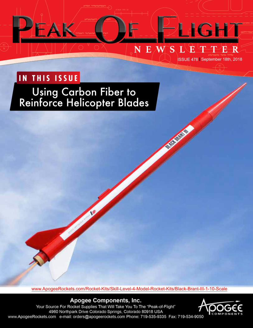
ISSUE 478 September 18th, 2018 Using Carbon Fiber to Reinforce Helicopter Blades www.ApogeeRockets.com/Rocket-Kits/Skill-Level-4-Model-Rocket-Kits/Black-Brant-III-1-10-Scale IN THIS ISSUE
Transcript of IN THIS ISSUE Using Carbon Fiber to Reinforce Helicopter ... 4: Carbon Fiber mat. Figure 5: Carbon...
ISSUE 478 September 18th, 2018
Using Carbon Fiber to
Reinforce Helicopter Blades
www.ApogeeRockets.com/Rocket-Kits/Skill-Level-4-Model-Rocket-Kits/Black-Brant-III-1-10-Scale
I N T H I S I S S U E

Continued on page 3
Making helicopter blades stiffer and lighter weight is the subject of this article. You may not be doing that exact same task, but the technique that I describe here may be applicable to something you need for one of your next projects.
I’m always trying to improve my helicopter rockets. Sometimes I try drastic changes, like completely changing the hub design and the blade shape (see the references at the end of this article). That is what I did when I was designing the FAI style helicopters 2-1/2 years ago when we were getting ready to head to Ukraine in 2016 for the World Space Modeling Championships. This year, since time would be in shorter supply because I knew Apogee would be moving to a different building, I decided to just improve the existing design.
The problem with my previous design was that it was a bit heavier compared to models that others were building and flying. In world-cup competition, the mass is critical, because a heavy model doesn’t fly as high as a lighter weight one. The higher you get the rocket launched, the longer it will take to descend down to the ground, and the better chance of it catching a thermal that will slow its descent even further.
More specifically, the weight of the helicopter was concentrated in the blades. Once the model was deployed in the air, the blades being heavier than the tube meant that they would tend to fall faster. This caused problems because the Center-of-Gravity (CG) needs to be below the hub in order for the rocket to start to spin up. Without it spinning up quickly upon deployment, the rocket fell too fast and lost a lot of altitudes.
Therefore my goal was to make the blades lighter weight, hoping that it would help the rocket to spin up faster.
The previous blades were made from 1/32-inch balsa wood, that was skinned with 0.5-ounce fiberglass cloth. They weighed about 3.5 grams each (Figure 1).
The question is how do you make the blades lighter? At the same time, I didn’t want to sacrifice any strength. So this is the engineering choices that were going through my mind as I was trying to come up with ways to make the blades lighter weight.
The first obvious choice was the possibility of going with thinner wood. I ruled that out pretty quick. The blades were already wafer thin, and making them any thinner
would have made them into limp noodles that wouldn’t hold their shape when deployed.
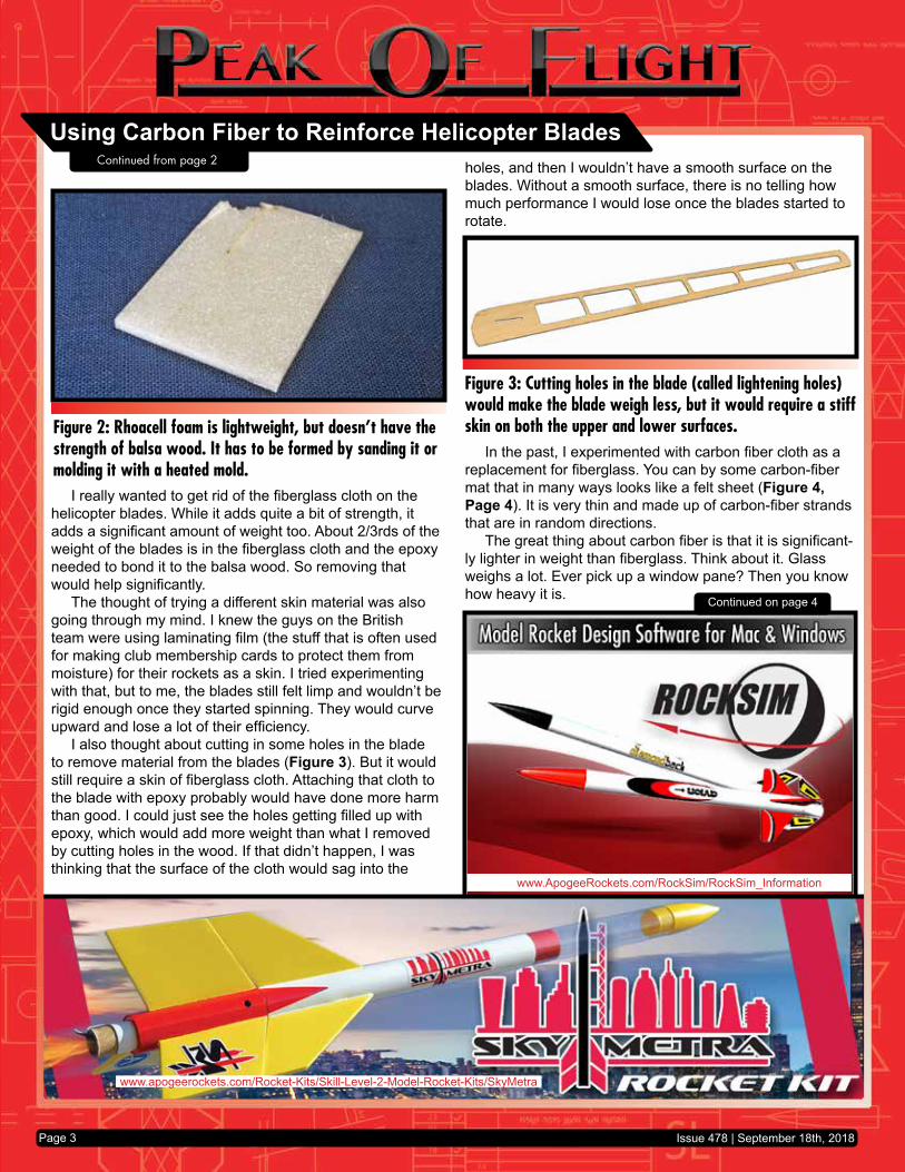
I also thought about switching from balsa wood to something less dense, like rhoacell foam sheet (Figure 2, Page 3). The issue I had with that is that I don’t have a lot of experience working with the material, and it isn’t much lighter than lightweight balsa. Balsa is a miracle material really. It has great low density and pretty high strength. The rhoacell foam is light but doesn’t have any strength unless it has a skin on it - like fiberglass cloth.
About this NewsletterYou can subscribe to receive this e-zine FREE at the Apogee Components website www.ApogeeComponents.com, or by clicking the link
here Newsletter Sign-Up
Newsletter StaffWriter: Tim Van MilliganLayout/Cover Artist: Chris DuranProofreader: Will Franks
Using Carbon Fiber to Reinforce Helicopter BladesBy Tim Van Milligan
Figure 1: My previous blades were made from 1/32-inch thick balsa wood that was skinned with ½-ounce fiberglass cloth. You can see the weave of the fiberglass is you look close enough.
Issue 478 | September 18th, 2018Page 2
www.ApogeeRockets.com/RockSim/RockSim_Information
www.apogeerockets.com/Rocket-Kits/Skill-Level-2-Model-Rocket-Kits/SkyMetra
Continued on page 4
holes, and then I wouldn’t have a smooth surface on the blades. Without a smooth surface, there is no telling how much performance I would lose once the blades started to rotate.
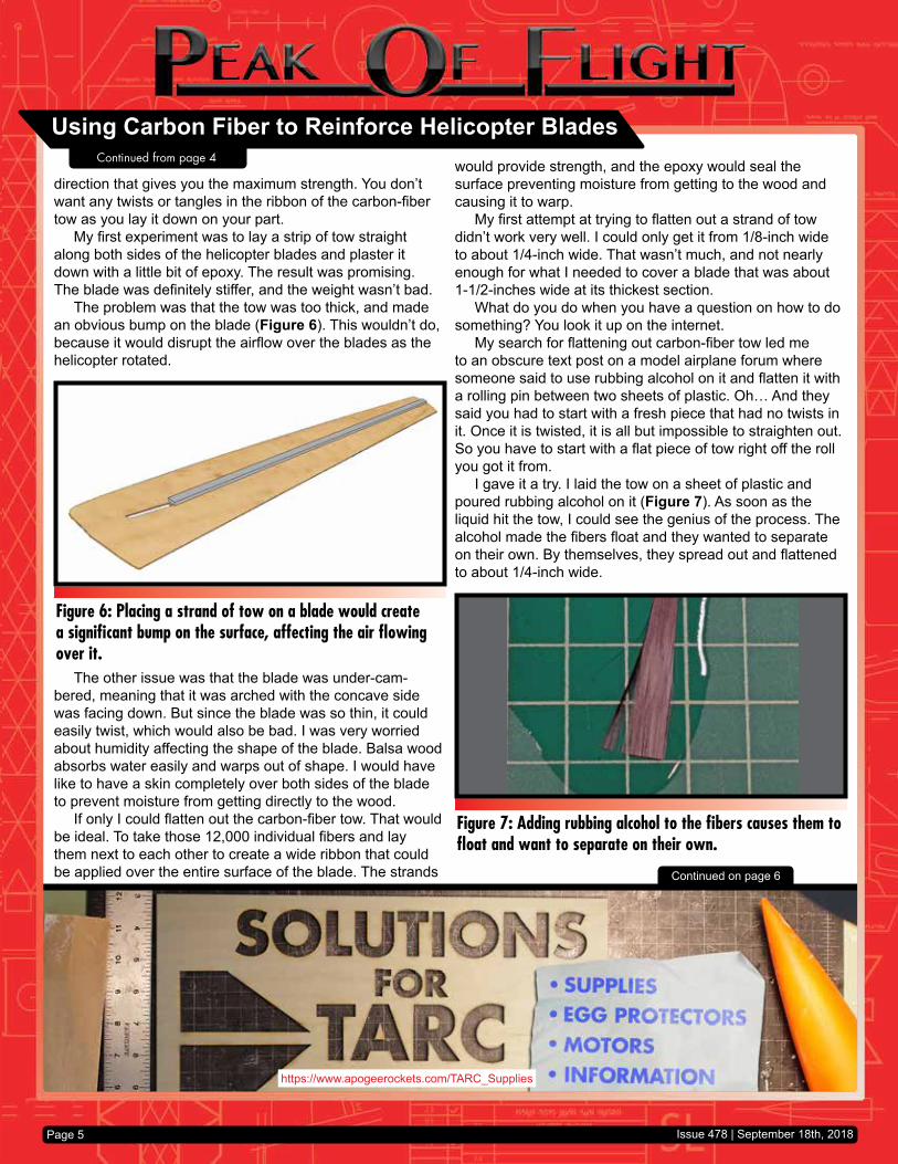
In the past, I experimented with carbon fiber cloth as a replacement for fiberglass. You can by some carbon-fiber mat that in many ways looks like a felt sheet (Figure 4, Page 4). It is very thin and made up of carbon-fiber strands that are in random directions.
The great thing about carbon fiber is that it is significant-ly lighter in weight than fiberglass. Think about it. Glass weighs a lot. Ever pick up a window pane? Then you know how heavy it is.
I really wanted to get rid of the fiberglass cloth on the helicopter blades. While it adds quite a bit of strength, it adds a significant amount of weight too. About 2/3rds of the weight of the blades is in the fiberglass cloth and the epoxy needed to bond it to the balsa wood. So removing that would help significantly.
The thought of trying a different skin material was also going through my mind. I knew the guys on the British team were using laminating film (the stuff that is often used for making club membership cards to protect them from moisture) for their rockets as a skin. I tried experimenting with that, but to me, the blades still felt limp and wouldn’t be rigid enough once they started spinning. They would curve upward and lose a lot of their efficiency.
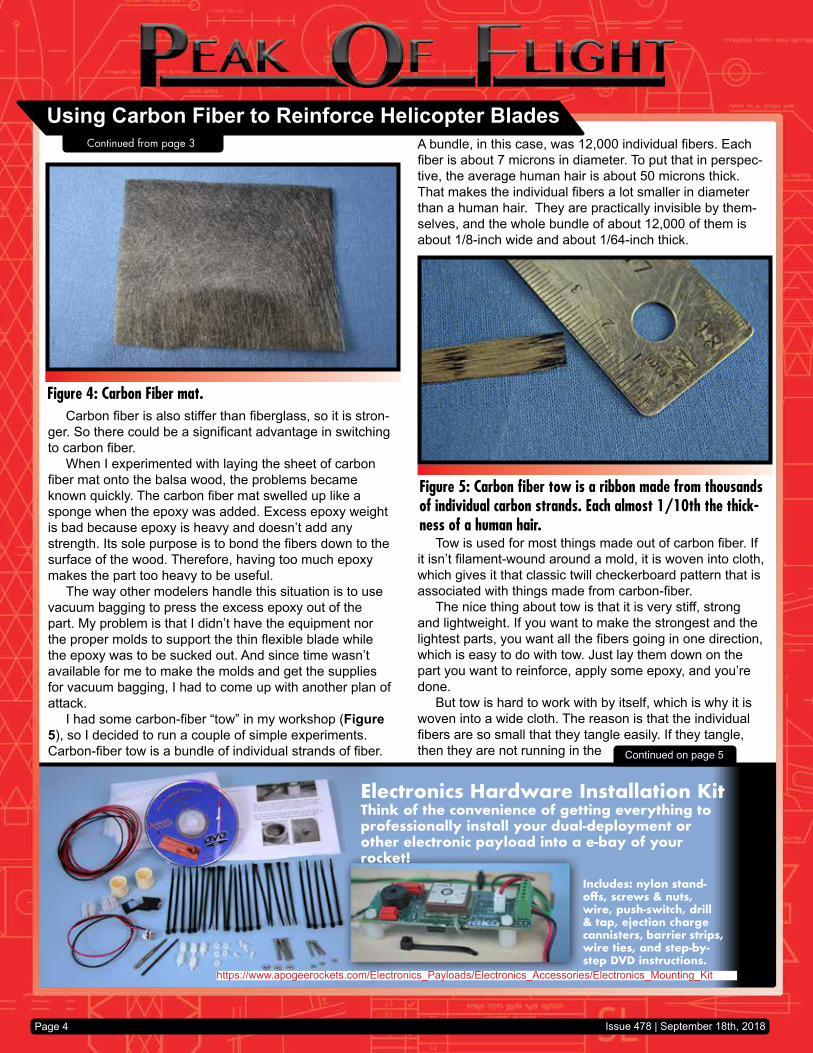
I also thought about cutting in some holes in the blade to remove material from the blades (Figure 3). But it would still require a skin of fiberglass cloth. Attaching that cloth to the blade with epoxy probably would have done more harm than good. I could just see the holes getting filled up with epoxy, which would add more weight than what I removed by cutting holes in the wood. If that didn’t happen, I was thinking that the surface of the cloth would sag into the
Figure 2: Rhoacell foam is lightweight, but doesn’t have the strength of balsa wood. It has to be formed by sanding it or molding it with a heated mold.
Figure 3: Cutting holes in the blade (called lightening holes) would make the blade weigh less, but it would require a stiff skin on both the upper and lower surfaces.
Using Carbon Fiber to Reinforce Helicopter Blades
Issue 478 | September 18th, 2018Page 3
Continued from page 2
Electronics Hardware Installation KitThink of the convenience of getting everything to professionally install your dual-deployment or other electronic payload into a e-bay of your rocket!
https://www.apogeerockets.com/Electronics_Payloads/Electronics_Accessories/Electronics_Mounting_Kit
Includes: nylon stand-offs, screws & nuts, wire, push-switch, drill & tap, ejection charge cannisters, barrier strips, wire ties, and step-by-step DVD instructions.
Page 4
Carbon fiber is also stiffer than fiberglass, so it is stron-ger. So there could be a significant advantage in switching to carbon fiber.
When I experimented with laying the sheet of carbon fiber mat onto the balsa wood, the problems became known quickly. The carbon fiber mat swelled up like a sponge when the epoxy was added. Excess epoxy weight is bad because epoxy is heavy and doesn’t add any strength. Its sole purpose is to bond the fibers down to the surface of the wood. Therefore, having too much epoxy makes the part too heavy to be useful.
The way other modelers handle this situation is to use vacuum bagging to press the excess epoxy out of the part. My problem is that I didn’t have the equipment nor the proper molds to support the thin flexible blade while the epoxy was to be sucked out. And since time wasn’t available for me to make the molds and get the supplies for vacuum bagging, I had to come up with another plan of attack.
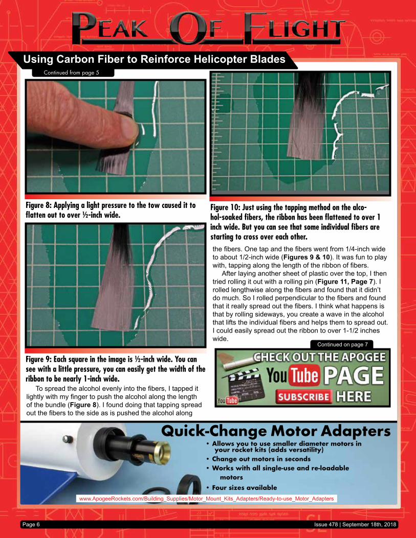
I had some carbon-fiber “tow” in my workshop (Figure 5), so I decided to run a couple of simple experiments. Carbon-fiber tow is a bundle of individual strands of fiber. Continued on page 5
A bundle, in this case, was 12,000 individual fibers. Each fiber is about 7 microns in diameter. To put that in perspec-tive, the average human hair is about 50 microns thick. That makes the individual fibers a lot smaller in diameter than a human hair. They are practically invisible by them-selves, and the whole bundle of about 12,000 of them is about 1/8-inch wide and about 1/64-inch thick.
Tow is used for most things made out of carbon fiber. If it isn’t filament-wound around a mold, it is woven into cloth, which gives it that classic twill checkerboard pattern that is associated with things made from carbon-fiber.
The nice thing about tow is that it is very stiff, strong and lightweight. If you want to make the strongest and the lightest parts, you want all the fibers going in one direction, which is easy to do with tow. Just lay them down on the part you want to reinforce, apply some epoxy, and you’re done.
But tow is hard to work with by itself, which is why it is woven into a wide cloth. The reason is that the individual fibers are so small that they tangle easily. If they tangle, then they are not running in the
Figure 4: Carbon Fiber mat.
Figure 5: Carbon fiber tow is a ribbon made from thousands of individual carbon strands. Each almost 1/10th the thick-ness of a human hair.
Using Carbon Fiber to Reinforce Helicopter BladesContinued from page 3
Issue 478 | September 18th, 2018
https://www.apogeerockets.com/TARC_Supplies
Page 5
direction that gives you the maximum strength. You don’t want any twists or tangles in the ribbon of the carbon-fiber tow as you lay it down on your part.
My first experiment was to lay a strip of tow straight along both sides of the helicopter blades and plaster it down with a little bit of epoxy. The result was promising. The blade was definitely stiffer, and the weight wasn’t bad.
The problem was that the tow was too thick, and made an obvious bump on the blade (Figure 6). This wouldn’t do, because it would disrupt the airflow over the blades as the helicopter rotated.
The other issue was that the blade was under-cam-bered, meaning that it was arched with the concave side was facing down. But since the blade was so thin, it could easily twist, which would also be bad. I was very worried about humidity affecting the shape of the blade. Balsa wood absorbs water easily and warps out of shape. I would have like to have a skin completely over both sides of the blade to prevent moisture from getting directly to the wood.
If only I could flatten out the carbon-fiber tow. That would be ideal. To take those 12,000 individual fibers and lay them next to each other to create a wide ribbon that could be applied over the entire surface of the blade. The strands
would provide strength, and the epoxy would seal the surface preventing moisture from getting to the wood and causing it to warp.
My first attempt at trying to flatten out a strand of tow didn’t work very well. I could only get it from 1/8-inch wide to about 1/4-inch wide. That wasn’t much, and not nearly enough for what I needed to cover a blade that was about 1-1/2-inches wide at its thickest section.
What do you do when you have a question on how to do something? You look it up on the internet.
My search for flattening out carbon-fiber tow led me to an obscure text post on a model airplane forum where someone said to use rubbing alcohol on it and flatten it with a rolling pin between two sheets of plastic. Oh… And they said you had to start with a fresh piece that had no twists in it. Once it is twisted, it is all but impossible to straighten out. So you have to start with a flat piece of tow right off the roll you got it from.
I gave it a try. I laid the tow on a sheet of plastic and poured rubbing alcohol on it (Figure 7). As soon as the liquid hit the tow, I could see the genius of the process. The alcohol made the fibers float and they wanted to separate on their own. By themselves, they spread out and flattened to about 1/4-inch wide.
Continued on page 6
Figure 6: Placing a strand of tow on a blade would create a significant bump on the surface, affecting the air flowing over it.
Figure 7: Adding rubbing alcohol to the fibers causes them to float and want to separate on their own.
Using Carbon Fiber to Reinforce Helicopter Blades
Issue 478 | September 18th, 2018
Continued from page 4
Quick-Change Motor Adapters• Allows you to use smaller diameter motors in
your rocket kits (adds versatility)• Change out motors in seconds• Works with all single-use and re-loadable motors • Four sizes available
www.ApogeeRockets.com/Building_Supplies/Motor_Mount_Kits_Adapters/Ready-to-use_Motor_Adapters
Page 6
Continued on page 7
To spread the alcohol evenly into the fibers, I tapped it lightly with my finger to push the alcohol along the length of the bundle (Figure 8). I found doing that tapping spread out the fibers to the side as is pushed the alcohol along
the fibers. One tap and the fibers went from 1/4-inch wide to about 1/2-inch wide (Figures 9 & 10). It was fun to play with, tapping along the length of the ribbon of fibers.
After laying another sheet of plastic over the top, I then tried rolling it out with a rolling pin (Figure 11, Page 7). I rolled lengthwise along the fibers and found that it didn’t do much. So I rolled perpendicular to the fibers and found that it really spread out the fibers. I think what happens is that by rolling sideways, you create a wave in the alcohol that lifts the individual fibers and helps them to spread out. I could easily spread out the ribbon to over 1-1/2 inches wide.
Figure 8: Applying a light pressure to the tow caused it to flatten out to over ½-inch wide.
Figure 9: Each square in the image is ½-inch wide. You can see with a little pressure, you can easily get the width of the ribbon to be nearly 1-inch wide.
Figure 10: Just using the tapping method on the alco-hol-soaked fibers, the ribbon has been flattened to over 1 inch wide. But you can see that some individual fibers are starting to cross over each other.
Using Carbon Fiber to Reinforce Helicopter Blades
Issue 478 | September 18th, 2018
Continued from page 5

You get:(4) AT 29/13(4) AT 41/18(2) AT 56/18(2) AT 66/18(1) AC-56(1) AC-66
You get:(6) AT 13/18(6) AT 18/18(6) AT 24/18(6) AT 33/18
www.ApogeeRockets.com/Building_Supplies/Body_Tubes
Page 7
Continued on page 8
However, the ribbon of fibers when I rolled it, did not stay straight. They took on a wavy appearance (Figure 12). I think you’ll need a rolling pin that is wider in length than the ribbon of fibers you’re trying to spread out. My rolling pin wasn’t wide enough, because my blades were so long.
I also saw that the fibers started to twist. That was bad. It had a bow-tie look to it (Figure 13), being skinny in the middle where the twist was. I could see now why you have to start with a fresh ribbon piece.
Once a ribbon is twisted, there isn’t any way you can get it untwisted after you’ve added the alcohol to it. About the only thing you can do is cut the ribbon at the twisted section and use the short piece for something else.
You will notice that once you apply the rolling pin to flat-ten out the ribbon, the alcohol is pushed out as well. This is good because then you can peel off the top layer of plastic, and there is very little alcohol on the carbon fiber. It evap-orates dry in a couple of minutes, and it is ready to use to reinforce the part you’re making. If you don’t use two layers of plastic, the fibers will stick to the rolling pin, which pretty much ruins the piece. But it is cheap, and you can easily start over.
Figure 11: Using a rolling pin, working (rolling) perpendicular to the length of the fibers, you can flatten them out much wider. But you’ll see bunches of fibers crossing over each other.
Figure 12: With the rolling pin pressure, the ribbon has flat-tened to nearly 4 inches wide.
Figure 13: The bow-tie look of a twisted strand, which is what you want to avoid because it is lumpy.
Using Carbon Fiber to Reinforce Helicopter Blades
Issue 478 | September 18th, 2018
Continued from page 6

Experienced HPR Builders Use Thrust Plates
• Eliminates Shear Forces on Centering Rings• Mates with AeroPacks Flanged Engine Retainers• Fits Standard HPR Tubes, Blue Tubes, and Fiberglass Tubes• Made from Aircraft Grade Aluminumhttps://www.apogeerockets.com/Building_Supplies/Thrust_Plates
Page 8
Being impatient, I take a paper towel and squeegee off any residual alcohol so it dries even faster. I’ve noticed that doing this also removes any of those stray fibers that are cross-span to the ribbon.
One nice thing about this process is that you can always re-wet the fibers with more alcohol and repeat the process if you don’t like the orientation of the fibers in the ribbon. I’ve found that it is impossible to get all the fibers perfectly straight in the flattened out ribbon. I wish I could, but for long parts like helicopter blades, the ribbon is going to be a little wavy and may have some sections where part of the bundle of fibers is twisted. I’ve come to accept this as a nuisance of the process, and something you have to live with. The finished product is still 10-times better than using a sheet of a carbon-fiber mat.
Once the alcohol has evaporated off, the thing that I no-ticed is the ribbon is much stiffer than I anticipated. When you peel it off the plastic (it comes up really easy), the ribbon hardly sags at all under its own weight (Figure 14).
It is relatively easy to handle too because it is stiff. But you have to move it around slowly so that a gust of wind doesn’t lift one end up and twist it over on itself.
Continued on page 9
Reinforcing the Helicopter BladesFor the helicopter blades that we were making, we
mixed up the epoxy and then thinned it out with some alco-hol. I did this because I didn’t want the epoxy to add to the weight of the part. I only wanted the thinnest film of epoxy to bond the fibers to the surface of the balsa wood.
Using rubber gloves, we applied the thinned out the epoxy to the bottom surface of the balsa blade, and spread it out evenly. I do the bottom surface first because it will be placed back on the mold (a large PVC pipe) while the ep-oxy cures so that maintains its special shape (Figure 15).
I removed the gloves from my hands to pick up the ribbon of carbon fiber. You can’t have any “stickiness” from epoxy on your hands when you handle the flattened-out carbon fiber ribbon. It is so lightweight and thin, that it has to be handled with care so that it doesn’t twist up on you or stick to your fingers as you lay it down on the wood.
As I said, you can easily lift it up off the plastic because it is stiff. I pick it up by both ends and let it bow downward slightly in the middle. I gently align it over the top of the blade and let the middle part of the fibers touch down first on the long balsa blade.
Figure 14: The dried ribbon of fibers. They are stiff, and hardly deflect from their own weight when you pick them up.
Figure 15: Allison Van Milligan applies thinned out epoxy to the bottom surface of the balsa blades.
Using Carbon Fiber to Reinforce Helicopter Blades
Issue 478 | September 18th, 2018
Continued from page 7
https://www.apogeerockets.com/Rocket-Kits/Skill-Level-3-Model-Rocket-Kits/Slo-Mo
Page 9
Continued on page 10
Be very careful not to disturb it at this point. It really isn’t laying flat yet on the balsa. it is sort of hovering over the wood, touching it at random places along the length. Don’t try to press it down yet, or you’ll twist it up.
I put my rubber gloves back on, and get a small saucer of rubbing alcohol. First, clean off the gloves of epoxy using a paper towel and some alcohol. You don’t want any sticky epoxy on your fingers yet.
Next, I dip my finger into the alcohol to pick up a cou-ple of drops of liquid and drizzle them on the middle of the blade. The alcohol immediately wicks along the fibers because of surface tension. The ribbon gets heavy from the extra weight of the alcohol and falls flat onto the long blade (right in the middle).
This is where you have to use both hands. Take one index finger and re-dip it in alcohol and place it flat across the fibers in the middle of the blade. Hold it there, and do not let it move. Dip the other index finger in alcohol, and lay it flat next to the first finger, and gently slide it along the fibers on the blade for about an inch or so. The alcohol soaked finger will slide fairly easily because the liquid lubri-cates the fibers. As soon as you feel the friction building up because the alcohol has run dry, lift your second finger off the blades. Move your finger in one direction only - away from the middle of the blade where your first index finger is holding the fibers down on the blade. Now you’ll re-dip your second index finger again and again as you repeat the process, each time starting at the place where you left off before. Remember, the first index finger is NOT to be lifted off the blade until you get to the end.
When you get to the end, one half of the blade will have the fibers pressed flat. Keep that first finger on the blade! You’ll dip the 2nd index finger back into the alcohol, and lay it next to the first index finger. Now you can slide that first finger way, and get more alcohol to repeat the process of sliding the fibers down onto the blade in the other direction. Don’t worry about using too much alcohol. It will evaporate away very quickly. Re-dip often to add more alcohol.
When you’re done, the fibers will be flat along the blade, but not really fixed to the surface yet. The little bit of epoxy you laid down will hold the fibers in place, but really it is just the fibers on the bottom of the thin ribbon. You still have to put more epoxy on top.
You’ll use the same technique of using your index fin-gers that you used with the alcohol, but this time, you’ll use the thinned out epoxy.
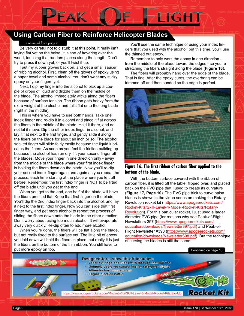
Remember to only work the epoxy in one direction - from the middle of the blade toward the edges - so you’re stretching the fibers straight along the blade (Figure 16).
The fibers will probably hang over the edge of the blade. That is fine. After the epoxy cures, the overhang can be trimmed off and then sanded so the edge is perfect.
With the bottom surface covered with the ribbon of carbon fiber, it is lifted off the table, flipped over, and placed back on the PVC pipe that I used to create its curvature (Figure 17, Page 10). The PVC pipe trick to curve balsa blades is shown in the video series on making the Rotary Revolution rocket kit ( https://www.apogeerockets.com/Rocket-Kits/Skill-Level-4-Model-Rocket-Kits/Rotary-Revolution). For this particular rocket, I just used a larger diameter PVC pipe (for reasons why see Peak-of-Flight Newsletters 397 (https://www.apogeerockets.com/education/downloads/Newsletter397.pdf) and Peak-of-Flight Newsletter #398 (https://www.apogeerockets.com/education/downloads/Newsletter398.pdf). But the technique of curving the blades is still the same.
Figure 16: The first ribbon of carbon fiber applied to the bottom of the blade.
Using Carbon Fiber to Reinforce Helicopter Blades
Issue 478 | September 18th, 2018
Continued from page 8
www.ApogeeRockets.com/Rocket_Kits/Scale_Rockets
Page 10
As you can see in the photos, the carbon fibers were not perfectly straight on the blades. They are very easy to disturb, and getting a perfect layup is difficult. We didn’t have time to try enough for perfection. It was good enough for our needs. Remember our goal was that we wanted the fibers to lay smooth on the blades without creating a large bump down the length that would interrupt the airflow over them. Even with some tangles in the ribbon, it was far better (flatter) than before.
Once all the blades were on the tube, another sheet of plastic was laid over the top of the blades and the epoxy (Figure 19). This plastic was smoothed out so the surface would be free of wrinkles in the plastic. Then the pipe was wrapped tightly with a long cloth strip (cut from an old bed sheet Figure 20, Page 11). This applied pressure to the carbon fiber so that any excess epoxy was squeezed out and so the blades held their shape while the epoxy cured. As I was describing this process to another modeler, he told me that he wrapped tubes like this with an ACE elastic bandage instead of a strip of cloth. The reason is the elastic bandage pulls tighter and squeezes out more epoxy. I wish I would have thought of that. It will definitely be something that I try in the future.
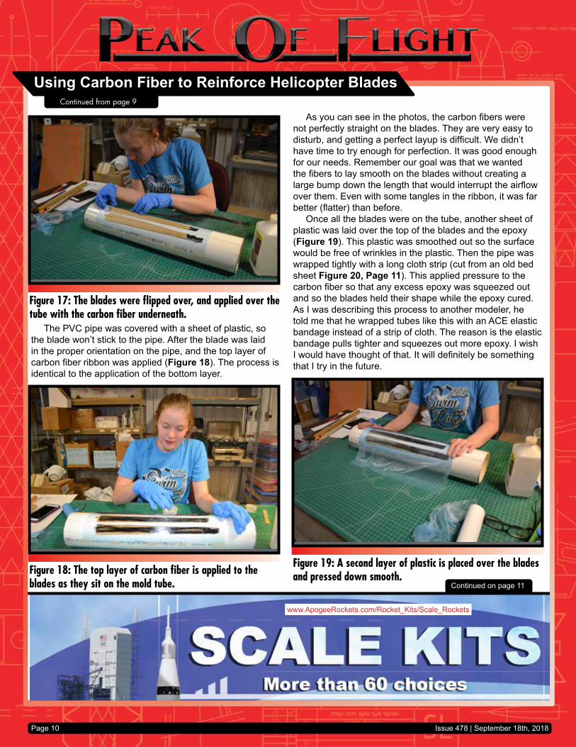
The PVC pipe was covered with a sheet of plastic, so the blade won’t stick to the pipe. After the blade was laid in the proper orientation on the pipe, and the top layer of carbon fiber ribbon was applied (Figure 18). The process is identical to the application of the bottom layer.
Continued on page 11
Figure 17: The blades were flipped over, and applied over the tube with the carbon fiber underneath.
Figure 18: The top layer of carbon fiber is applied to the blades as they sit on the mold tube.
Figure 19: A second layer of plastic is placed over the blades and pressed down smooth.
Using Carbon Fiber to Reinforce Helicopter Blades
Issue 478 | September 18th, 2018
Continued from page 9

www.ApogeeRockets.com/RockSim/RockSim_Information
Page 11
When the epoxy was cured hard, the blades were re-moved and trimmed around the edges, and lightly sanded on the surface. You have to be careful sanding because the carbon fiber is so thin that it is easy to sand through it. I used 400 grit sandpaper just to even out the surface.
I was pleased with the overall stiffness and weight of the blades. They came out about 1.3 grams lighter in weight than the previous ones that were skinned with fiberglass cloth. They were also stiffer and resistant to warping from humidity. That was a big benefit since we didn’t have to try to reform the blades on the field when the humidity was about 80%.
Even with the tangles in some areas of the blades, they were still stronger, stiffer, and lighter weight compared to 0.5-ounce fiberglass cloth. I would definitely recommend this process to other modelers that are trying to strengthen parts while minimizing the weight.
The only downside is that they are black in color. This is OK for when the rocket is in the sky, as it makes the model more visible. But once it lands on the ground, black doesn’t stand out. Of course, neither does brown balsa wood. And they aren’t pretty, but they are functional.
While the blades were lighter, they were still not light-weight enough. In the actual competition this summer at the WSMC in Poland, the helicopters didn’t initially fall with the body tube below the hub. The tube is so lightweight, that it still falls just as slow than the blades. But once it got oriented, where the body was below the hub, the thing spun up nicely and worked like a charm. However, the models lost too much altitude and didn’t have a chance to catch a good thermal.
Continued on page 12
Figure 20: The tube is wound with a long cloth stip that holds the blades tight against the mold.
Figure 21: The finished blade, which was sanded lightly with 400 grit sandpaper.
Figure 22: The underside of the helicopter hub. The blades look ugly, but they are very thin and very stiff.
Using Carbon Fiber to Reinforce Helicopter Blades
Issue 478 | September 18th, 2018
Continued from page 10

Page 12
ered rocket gliders. The tapered tubes that were a result were about 22 inches long and weighed about 2.5 grams. And they were very very stiff. They are really cool. So cool, that I’ll show you how I made them in a future issue of the Peak-of-Flight Newsletter.
About The Author:Tim Van Milligan (a.k.a. “Mr. Rocket”) is a real rocket
scientist who likes helping out other rocketeers. He is an avid rocketry competitor and is Level 3 high power certified. He is often asked what is the biggest rocket he’s ever launched. His answer is that before he started writing articles and books about rocketry, he worked on the Delta II rocket that launched satellites into orbit. He has a B.S. in Aeronautical Engineering from Embry-Riddle Aeronautical University in Daytona Beach, Florida, and has worked toward an M.S. in Space Technology from the Florida Institute of Technology in Melbourne, Florida. Currently, he is the owner of Apogee Components (http://www.apogeerockets.com) and also the author of the books: Model Rocket Design and Construction, 69 Simple Science Fair Projects with Model Rockets: Aeronautics and publisher of the Peak-of-Flight newsletter, a FREE ezine newsletter about model rockets. You can email him by using the contact form at https://www.apogeerockets.com/Contact.
References:Fabrication of Shaped and Curved Helicopter Rotor
Blades - https://www.apogeerockets.com/education/downloads/Newsletter342.pdf
Finding the Best Gyrocopter Blade Shape and Best Place to Attach the Blade - https://www.apogeerockets.com/education/downloads/Newsletter381.pdf
The Effect of Blade Curvature and Angle-of-Attack on Helicopter Descent - https://www.apogeerockets.com/education/downloads/Newsletter397.pdf
The Effect of Twisting Helicopter Blades at an Angle On Duration - https://www.apogeerockets.com/education/downloads/Newsletter398.pdf
Development of a New and Simplified Helicopter Rotor Hub - https://www.apogeerockets.com/education/downloads/Newsletter375.pdf
When I test flew these helicopters previously with the Estes A3-4T motors, which are significantly heavier than the European motors that were used in the competition, the model thermal-ed away quite regularly. So the learning I got from the contest was that I need to make the body tube heavier to get it to fall faster than the hub. Strange, huh? I have to make it heavier so that it stays in the air longer.
Where else could you use this technique?For model airplanes, this process of flattening carbon-fi-
ber tow would be a great technique for making lightweight and stiff wings. The NAR’s glider competition for 1/4A rocket motor is just begging for this because you have to make the gliders super lightweight to get them to boost high enough on a 1/4A-3 motor. That 3-second delay is really too long for the power of a 1/4A motor. Usually, you’d be arching the model over the top during boost and it will lose a lot of altitudes. A 2-second delay would be better, but Es-tes only currently manufactures the 1/4A motor in a 3-sec-ond delay, so that is what you have to design your rocket around. With that limitation, to get more altitude, you have to build light and probably use a piston launcher too. But if you’re using a piston launcher, you need to make the model durable enough to withstand the higher lift-off speeds. So going with reinforced carbon-fiber wings is probably a really good idea.
Another place you could use this technique for is rein-forcing balsa fins. If you need the extra strength, this is the way to go. I didn’t use the fins I made with the carbon on them for competition, but that was because the fins on the rockets were already stiff enough. So I didn’t want to add the extra weight. But if you need “strength,” then this is a great way to add it without adding a lot of weight.
I’ve also used this technique of separating and flattening carbon-fiber tow to roll fuselage booms for A-engine pow-
Figure 23: A fin that has been stiffened with spread-out carbon fiber tow.
Using Carbon Fiber to Reinforce Helicopter BladesContinued from page 11
Issue 478 | September 18th, 2018