In This Chapter - Jim Richardsonrichardson.eng.ua.edu/Former_Courses/AutoCAD_Help/aug_18.pdf ·...
41
In This Chapter 619 18 Creating Three- Dimensional Objects Because drawings that are two-dimensional representations of three-dimensional objects must be visually interpreted, you may want to create true 3D models instead of 2D representations. You can use the AutoCAD ® drawing tools to create detailed, realistic 3D objects and manipulate them in various ways. ■ Creating wireframe models, surface models, and solid objects ■ Creating composite solids ■ Using elevation and thickness to create 3D objects ■ Trimming, extruding, chamfering, and filleting 3D objects ■ Rotating, copying, and mirroring 3D objects ■ Editing 3D solid faces and edges ■ Shelling 3D solids
Transcript of In This Chapter - Jim Richardsonrichardson.eng.ua.edu/Former_Courses/AutoCAD_Help/aug_18.pdf ·...

In This Chapter
619
18
Creating Three-Dimensional Objects
Because drawings that are two-dimensional
representations of three-dimensional objects
must be visually interpreted, you may want to
create true 3D models instead of 2D representations.
You can use the AutoCAD® drawing tools to create
detailed, realistic 3D objects and manipulate them in
various ways.
■ Creating wireframe models, surface models, and solid objects
■ Creating composite solids
■ Using elevation and thickness to create 3D objects
■ Trimming, extruding, chamfering, and filleting 3D objects
■ Rotating, copying, and mirroring 3D objects
■ Editing 3D solid faces and edges
■ Shelling 3D solids

620 | Chapter 18 Creating Three-Dimensional Objects
Creating Objects in 3D
Although 3D models can be more difficult and time-consuming to create than 3D views of 2D objects, 3D modeling has several advantages. You can
■ View the model from any vantage point■ Generate reliable standard and auxiliary 2D views automatically■ Create 2D profiles■ Remove hidden lines and do realistic shading■ Check interference■ Export the model to create an animation■ Do engineering analysis■ Extract manufacturing data
AutoCAD supports three types of 3D modeling: wireframe, surface, and solid. Each type has its own creation and editing techniques.
A wireframe model is a skeletal description of a 3D object. There are no sur-faces in a wireframe model; it consists only of points, lines, and curves that describe the edges of the object. With AutoCAD you can create wireframe models by positioning 2D (planar) objects anywhere in 3D space. AutoCAD also provides some 3D wireframe objects, such as 3D polylines (that can only have a CONTINUOUS linetype) and splines. Because each object that makes up a wireframe model must be independently drawn and positioned, this type of modeling can be the most time-consuming.
Surface modeling is more sophisticated than wireframe modeling in that it defines not only the edges of a 3D object, but also its surfaces. The AutoCAD surface modeler defines faceted surfaces using a polygonal mesh. Because the faces of the mesh are planar, the mesh can only approximate curved surfaces. With Mechanical Desktop®, you can create true curved surfaces. To differen-tiate these two types of surfaces, AutoCAD calls faceted surfaces, meshes.
Solid modeling is the easiest type of 3D modeling to use. With the AutoCAD solid modeler, you can make 3D objects by creating basic 3D shapes: boxes, cones, cylinders, spheres, wedges, and tori (donuts). You can then combine these shapes to create more complex solids by joining or subtracting them or finding their intersecting (overlapping) volume. You can also create solids by sweeping a 2D object along a path or revolving it about an axis. With Mechanical Desktop, you can also define solids parametrically and maintain associativity between 3D models and the 2D views that you generate from them.
3D wireframe
mesh
solid

Creating Objects in 3D | 621
WARNING! Because each modeling type uses a different method for con-structing 3D models and editing methods vary in their effect on the different model types, it is recommended that you not mix modeling methods. Limited conversion between model types is available from solids to surfaces and from surfaces to wireframes; however, you cannot convert from wireframes to surfaces or from surfaces to solids.
Creating Wireframes
With AutoCAD you can create wireframe models by positioning any 2D planar object anywhere in 3D space. You can position 2D objects in 3D space by using any of the following methods:
■ Creating the object by entering 3D points. You enter a coordinate that defines the X, Y, and Z location of the point (see “Specifying 3D Coordi-nates” on page 582).
■ Setting the default construction plane (XY plane) on which you will draw the object by defining a UCS (see “Defining a User Coordinate System” on page 589).
■ Moving the object to its proper orientation in 3D space after you create it (see “Editing in 3D” on page 639).
Also, you can create some wireframe objects, such as polylines and splines, that can exist in all three dimensions. The following illustration is an ex-ample of a 3D modeling application using a combination of 3D polylines and 2D symbology positioned in 3D space.
Piping diagram composed of 3D polylines and 2D symbology

622 | Chapter 18 Creating Three-Dimensional Objects
Creating Meshes
A mesh represents an object’s surface using planar facets. The mesh density, or number of facets, is defined in terms of a matrix of M and N vertices, sim-ilar to a grid consisting of columns and rows. M and N specify the column and row position, respectively, of any given vertex. You can create meshes in both 2D and 3D, but they are used primarily for 3D.
Use meshes if you need hiding, shading, and rendering capabilities that wireframes don’t provide but do not need the physical properties that solids provide (mass, weight, center of gravity, and so on). Meshes are also useful if you want to create geometry with unusual mesh patterns, such as a 3D topo-graphical model of mountainous terrain.
A mesh can be open or closed. A mesh is open in a given direction if the start and end edges of the mesh do not touch, as shown in the following illustrations.
Open and closed meshes
AutoCAD provides several methods for creating meshes. Some of these methods can be difficult to use if you are entering the mesh parameters manually, so AutoCAD provides the 3D command, which simplifies the process of creating the basic surface shapes.
M openN open
M closedN open
M openN closed
M closedN closed

Creating Objects in 3D | 623
Creating a Predefined 3D Surface MeshThe 3D command creates the following 3D shapes: boxes, cones, dishes, domes, meshes, pyramids, spheres, tori (donuts), and wedges. These are meshes that are displayed as wireframes until you use HIDE, RENDER, or SHADEMODE.
To view the objects you are creating with the 3D command more clearly, set a viewing direction with 3DORBIT, DVIEW, or VPOINT. The procedures for creating 3D shapes are similar to those for creating 3D solids. For more information, see “Creating Solids” on page 632.
In the following illustrations, the numbers indicate points you specify to create the mesh.
Surface meshes created with the 3D command
height
width
1
length
height
top radius
1
base radius
M
N
4 3
2
1
1
radius
1
radius
1
2
3
radius
1
apex
1
2
3
4 height
1
length
width

624 | Chapter 18 Creating Three-Dimensional Objects
Creating a Rectangular MeshWith the 3DMESH command, you can create polygon meshes that are open in both the M and N directions (similar to the X and Y axes of an XY plane). You can close the meshes with PEDIT. You can use 3DMESH to construct very irregular surfaces. In most cases, you can use 3DMESH in conjunction with scripts or AutoLISP routines when you know the mesh points.
Example of rectangular mesh application
To create a rectangular mesh
1 From the Draw menu, choose Surfaces ➤ 3D Mesh.
2 Specify the M size, using an integer from 2 through 256.
3 Specify the N size, using an integer from 2 through 256.
4 Specify the vertex points as prompted. Specifying the last vertex point completes the mesh.
Examples of different M and N values
Command line 3DMESH
Related 3DFACE creates a 3D face. EDGE changes the visibility of 3D face edges. The Mesh option of 3D creates four-cornered planar meshes.
Mesh M size: 2Mesh N size: 2
Mesh M size: 2Mesh N size: 3
Mesh M size: 3Mesh N size: 3

Creating Objects in 3D | 625
In the following example of text on the command line, you enter a coordi-nate for each vertex to create the mesh in the illustration.
Example:Command: 3dmeshMesh M size: 4Mesh N size: 3Vertex (0, 0): 10,1,3Vertex (0, 1): 10,5,5Vertex (0, 2): 10,10,3Vertex (1, 0): 15,1,0Vertex (1, 1): 15,5,0Vertex (1, 2): 15,10,0Vertex (2, 0): 20,1,0Vertex (2, 1): 20,5,–1Vertex (2, 2): 20,10,0Vertex (3, 0): 25,1,0Vertex (3, 1): 25,5,0Vertex (3, 2): 25,10,0
Creating a Polyface MeshThe PFACE command produces a polyface (polygon) mesh, with each face capable of having numerous vertices.
Creating a polyface mesh is similar to creating a rectangular mesh. To create a polyface mesh, you specify coordinates for its vertices. You then define each face by entering vertex numbers for all the vertices of that face. As you create the polyface mesh, you can set specific edges to be invisible, assign them to layers, or give them colors.
M direction
N direction

626 | Chapter 18 Creating Three-Dimensional Objects
To make the edge invisible, enter the vertex number as a negative value. For instance, to make the edge between vertices 5 and 7 invisible in the following illustration, you enter the following:
Face 3, vertex 3: –7
In the illustration, face 1 is defined by vertices 1, 5, 6, and 2. Face 2 is defined by vertices 1, 4, 3, and 2. Face 3 is defined by vertices 1, 4, 7, and 5, and face 4 is defined by vertices 3, 4, 7, and 8.
You can control the display of invisible edges with the SPLFRAME system variable. If SPLFRAME is set to a nonzero value, the invisible edges become visible and can then be edited. If SPLFRAME is set to 0, the invisible edges remain invisible.
Display of invisible edges
Creating a Ruled Surface MeshWith RULESURF, you can create a surface mesh between two objects. You use two different objects to define the edges of the ruled surface: lines, points, arcs, circles, ellipses, elliptical arcs, 2D polylines, 3D polylines, or splines. Pairs of objects to be used as the “rails” of a ruled surface mesh must both be either open or closed. You can pair a point object with either an open or a closed object.
3
46
2
8
5
1
7
face 4
face 2
face 3
face 1
invisible edges
SPLFRAME = 1 SPLFRAME = 0

Creating Objects in 3D | 627
To create a ruled surface
1 From the Draw menu, choose Surfaces ➤ Ruled Surface.
2 Select the first defining curve. Then select the second (1 and 2).
3 Erase the original curve if necessary.
Command line RULESURF
System variables SURFTAB1 and SURFTAB2 control mesh density (number of facets) in the M and N directions, respectively.
You can specify any two points on closed curves to complete RULESURF. For open curves, AutoCAD starts construction of the ruled surface based on the locations of the specified points on the curves.
Comparison of ruled surfaces created by specifying points on opposite sides
curves defined result
1
2
specified points oncorresponding sides
result
specified points onopposite sides
result
628 | Chapter 18 Creating Three-Dimensional Objects
Creating a Tabulated Surface MeshWith the TABSURF command, you can create a surface mesh representing a general tabulated surface defined by a path curve and a direction vector. The path curve can be a line, arc, circle, ellipse, elliptical arc, 2D polyline, 3D polyline, or spline. The direction vector can be a line or an open 2D or 3D polyline. TABSURF creates the mesh as a series of parallel polygons running along a specified path. You must have the original object and the direction vector already drawn, as shown in the following illustrations.
To create a tabulated surface mesh
1 From the Draw menu, choose Surfaces ➤ Tabulated Surface.
2 Specify a path curve (1).
3 Specify a direction vector (2).
4 Erase the original objects if necessary.
Command line TABSURF
System variables SURFTAB1 and SURFTAB2 control the mesh density (num-ber of facets) in the M and N directions, respectively.
Creating a Surface of Revolution MeshUse the REVSURF command to create a surface of revolution by rotating a profile of the object about an axis. REVSURF is useful for surfaces with rota-tional symmetry.
To create a surface of revolution mesh
1 From the Draw menu, choose Surfaces ➤ Revolved Surface.
2 Specify a path curve (1).
The path curve, which defines the N direction of the mesh, can be a line, arc, circle, ellipse, elliptical arc, 2D polyline, 3D polyline, or spline. If you select a circle, closed ellipse, or closed polyline, AutoCAD closes the mesh in the N direction.
object specified direction vector specified result
1
2

Creating Objects in 3D | 629
3 Specify the axis of revolution (2).
The direction vector can be a line or an open 2D or 3D polyline. If you choose a polyline, the vector sets the rotation axis from its first vertex to its last vertex. AutoCAD ignores any intermediate vertices. The axis of revolution determines the M direction of the mesh.
4 Specify the start angle. Then specify the included angle.
If you specify a nonzero start angle, AutoCAD generates the mesh at a position offset from the path curve by that angle. The included angle specifies how far about the axis of revolution the surface should extend.
5 Erase the original objects if necessary.
Command line REVSURF
System variables SURFTAB1 and SURFTAB2 control mesh density (number of facets) in the M and N directions, respectively.
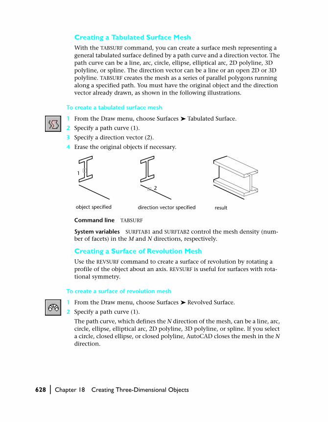
Creating an Edge-Defined Surface MeshWith the EDGESURF command, you can create a Coons surface patch mesh, as shown in the following illustration, from four objects called edges. Edges can be arcs, lines, polylines, splines, and elliptical arcs, and they must form a closed loop and share endpoints. A Coons patch is a bicubic surface (one curve in the M direction and another in the N direction) interpolated be-tween the four edges.
profile specified axis of revolution specified result
1
2
630 | Chapter 18 Creating Three-Dimensional Objects
To create an edge-defined Coons surface patch mesh
1 From the Draw menu, choose Surfaces ➤ Edge Surface.
2 Select the four edges in any order.
The first edge you select determines the mesh’s M direction.
Command line EDGESURF
System variables SURFTAB1 and SURFTAB2 control mesh density (number of facets) in the M and N direction, respectively.
Setting Elevation and ThicknessThickness and elevation are methods of simulating meshes in AutoCAD. The advantage of using elevation and thickness instead of a mesh is that you can change them quickly and easily for both new and existing objects.
The elevation of an object is the Z value of the XY plane on which the ob-ject base is drawn. An elevation of 0 indicates the base XY plane of the cur-rent UCS. Positive elevations are above this plane, and negative elevations are below it.
The thickness of an object is the distance that object is extruded above or below its elevation. Positive thickness extrudes upward (positive Z), nega-tive thickness extrudes downward (negative Z), and 0 thickness means no extrusion. An object with elevation 0 and a thickness of –1 unit appears identical to an object with an elevation of –1 and a thickness of 1 unit. The Z direction is determined by the orientation of the UCS at the time the ob-ject was created.
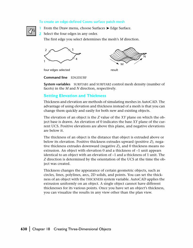
Thickness changes the appearance of certain geometric objects, such as circles, lines, polylines, arcs, 2D solids, and points. You can set the thick-ness of an object with the THICKNESS system variable. AutoCAD applies the extrusion uniformly on an object. A single object cannot have different thicknesses for its various points. Once you have set an object’s thickness, you can visualize the results in any view other than the plan view.
four edges selected result
1
2 3
4N
M
Creating Objects in 3D | 631
Like any other meshes, objects with thickness can be hidden, shaded, and rendered.
Consider the following when you change or set elevation and thickness:
■ 3D faces, 3D polylines, 3D polygon meshes, dimensions, and viewport objects ignore the current thickness and cannot be extruded. Modify-ing the thickness of these objects with CHANGE does not affect their appearance.
■ When you create new text objects or attribute definition objects, AutoCAD assigns the objects a 0 thickness regardless of the current thickness setting.
■ Line segments produced by SKETCH are extruded after the Record option is selected.
■ The current elevation established by the ELEV command remains in effect as you change from one UCS to another, and it defines the drawing plane of the current UCS.
You can set the elevation and thickness for new objects you create in AutoCAD. You can see the results in any view other than plan view.
To set the thickness of new objects
1 At the Command prompt, enter thickness.
2 Enter a thickness value in units.
3 Draw the objects.
AutoCAD draws the objects at the current elevation and thickness. To change these settings and draw additional objects, repeat steps 1 and 2.
Any text objects you create with ATTDEF or TEXT (either attribute definitions ordinary text) are assigned a zero thickness regardless of the current thickness setting. You can assign these objects a nonzero thickness with CHANGE, CHPROP, PROPERTIES.
You can change the elevation and thickness for existing objects. You can see the results in any view other than plan view.
2D objects elevation changed thickness added

632 | Chapter 18 Creating Three-Dimensional Objects
To change the thickness of existing objects
1 From the Modify menu, choose Properties.
2 Select the objects to change.
3 In the Properties window, enter the new thickness in units.
4 Press ENTER to exit the command.
Command line PROPERTIES
Shortcut menu Select the objects to change, right-click in the drawing area, and choose Properties.
System variables THICKNESS controls the current thickness.
Related CHANGE, CHPROP, and PROPERTIES alter the characteristics of exist-ing objects. To change the elevation of an existing object, move it in the Z direction.
Creating Solids
A solid object represents the entire volume of an object. Solids are the most informationally complete and least ambiguous of the 3D modeling types. Complex solid shapes are also easier to construct and edit than wireframes and meshes.
You create solids from one of the basic solid shapes of box, cone, cylinder, sphere, torus, and wedge or by extruding a 2D object along a path or revolv-ing a 2D object about an axis.
Once you have created a solid in this manner, you can create more complex shapes by combining solids. You can join solids, subtract solids from each other, or find the common volume (overlapping portion) of solids. For more information, see “Creating a Composite Solid” on page 638.
Solids can be further modified by filleting, chamfering, or changing the color of their edges. Faces on solids are easily manipulated because they don’t re-quire you to draw any new geometry or perform Boolean operations on the solid. AutoCAD also provides commands for slicing a solid into two pieces or obtaining the 2D cross section of a solid (see “Changing 3D Solids” on page 645).
Like meshes, solids are displayed as wireframes until you hide, shade, or render them. Additionally, you can analyze solids for their mass properties (volume, moments of inertia, center of gravity, and so on). You can export data about a solid object to applications such as NC (numerical control) milling or FEM (finite element method) analysis. By exploding a solid, you can break it down to mesh and wireframe objects.

Creating Objects in 3D | 633
The ISOLINES system variable controls the number of tessellation lines used to visualize curved portions of the wireframe. The FACETRES system variable adjusts the smoothness of shaded and hidden-line objects.
Creating a Solid BoxYou can use BOX to create a solid box. The base of the box is always parallel to the XY plane of the current UCS.
To create a solid box
1 From the Draw menu, choose Solids ➤ Box.
2 Specify the first corner of the base (1).
3 Specify the opposite corner of the base (2).
4 Specify the height (3).
Command line BOX
Related The RECTANG or PLINE command creates a rectangle or closed polyline from which you can create a box using EXTRUDE. 3D creates a box shape defined by surfaces only.
Creating a Solid ConeYou can use CONE to create a solid cone defined by a circular or an elliptical base tapering to a point perpendicular to its base. By default, the cone’s base lies on the XY plane of the current UCS. The height, which can be positive or negative, is parallel to the Z axis. The apex determines the height and ori-entation of the cone.
To create a truncated cone or a cone that requires a specific angle to define its sides, draw a 2D circle and then use EXTRUDE to taper the circle at an angle along the Z axis. To complete the truncation, you can subtract a box from the tip of the cone with the SUBTRACT command.
To create a solid cone with a circular base
1 From the Draw menu, choose Solids ➤ Cone.
2 Specify the base center point (1).
3 Specify the radius or diameter of the base (2).
4 Specify the height (3).
Command line CONE
Related CIRCLE creates a circle from which you can create a cone using EXTRUDE with its Taper option. 3D creates a conical shape defined by surfaces only.
1
3
2
1
3
2

634 | Chapter 18 Creating Three-Dimensional Objects
To create a solid cone with an elliptical base
1 From the Draw menu, choose Solids ➤ Cone.
2 Enter e (Elliptical).
3 Specify an axis endpoint.
4 Specify a second axis endpoint.
5 Specify the length of the other axis.
6 Specify height, and then press ENTER.
Command line CONE
Creating a Solid CylinderYou can use CYLINDER to create a solid cylinder with a circular or an elliptical base. The base of the cylinder lies on the XY plane of the current UCS.
If you want to construct a cylinder with special detail, such as grooves along its sides, create a 2D profile of its base with a closed PLINE and use EXTRUDE to define its height along the Z axis.
To create a solid cylinder with a circular base
1 From the Draw menu, choose Solids ➤ Cylinder.
2 Specify the base center point (1).
3 Specify the radius or diameter of the base (2).
4 Specify the height (3).
Command line CYLINDER
Related CIRCLE creates a circle from which you can create a cylinder using EXTRUDE.
Creating a Solid SphereYou can use SPHERE to create a solid sphere based on a center point and a radius or diameter. Its latitudinal lines are parallel to the XY plane, and the central axis is coincident with the Z axis of the current UCS.
To create a dome or dish, combine a sphere with a box and use SUBTRACT. If you want to create a spherical object that has additional detail, create a 2D profile and use REVOLVE to define a rotation angle about the Z axis.
1
2
3

Creating Objects in 3D | 635
To create a solid sphere
1 From the Draw menu, choose Solids ➤ Sphere.
2 Specify the center of the sphere (1).
3 Specify the radius or diameter of the sphere (2).
Command line SPHERE
Related 3D creates a spherical shape defined by surfaces only.
Creating a Solid TorusYou can use TORUS to create a ring-shaped solid similar to the inner tube of a tire. The torus is parallel to and bisected by the XY plane of the current UCS.
To create a solid torus
1 From the Draw menu, choose Solids ➤ Torus.
2 Specify the center of the torus (1).
3 Specify the radius or diameter of the torus (2).
4 Specify the radius or diameter of the tube (3).
Command line TORUS
Related 3D creates a toroidal shape defined by surfaces only.
To create a lemon-shaped solid, use a negative torus radius and a positive number of greater magnitude for the tube radius. For example, if the torus radius is –2.0, the tube radius must be greater than 2.0.
A torus may be self-intersecting. A self-intersecting torus has no center hole because the radius of the tube is greater than the radius of the torus.
Creating a Solid WedgeYou can use WEDGE to create a solid wedge. The base of the wedge is parallel to the XY plane of the current UCS with the sloped face opposite the first corner. Its height, which can be positive or negative, is parallel to the Z axis.
To create a solid wedge
1 From the Draw menu, choose Solids ➤ Wedge.
2 Specify the first corner of the base (1).
3 Specify the opposite corner of the base (2).
4 Specify the height of the wedge (3).
Command line WEDGE
Related 3D creates a wedge shape defined by surfaces only.
2
1
13
2
1
3
2
636 | Chapter 18 Creating Three-Dimensional Objects
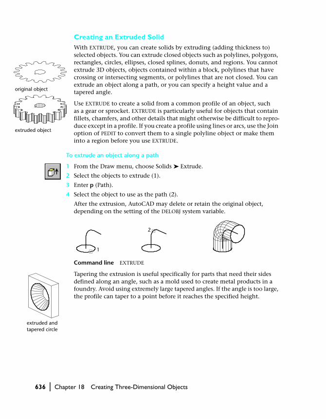
Creating an Extruded SolidWith EXTRUDE, you can create solids by extruding (adding thickness to) selected objects. You can extrude closed objects such as polylines, polygons, rectangles, circles, ellipses, closed splines, donuts, and regions. You cannot extrude 3D objects, objects contained within a block, polylines that have crossing or intersecting segments, or polylines that are not closed. You can extrude an object along a path, or you can specify a height value and a tapered angle.
Use EXTRUDE to create a solid from a common profile of an object, such as a gear or sprocket. EXTRUDE is particularly useful for objects that contain fillets, chamfers, and other details that might otherwise be difficult to repro-duce except in a profile. If you create a profile using lines or arcs, use the Join option of PEDIT to convert them to a single polyline object or make them into a region before you use EXTRUDE.
To extrude an object along a path
1 From the Draw menu, choose Solids ➤ Extrude.
2 Select the objects to extrude (1).
3 Enter p (Path).
4 Select the object to use as the path (2).
After the extrusion, AutoCAD may delete or retain the original object, depending on the setting of the DELOBJ system variable.
Command line EXTRUDE
Tapering the extrusion is useful specifically for parts that need their sides defined along an angle, such as a mold used to create metal products in a foundry. Avoid using extremely large tapered angles. If the angle is too large, the profile can taper to a point before it reaches the specified height.
original object
extruded object
2
1
extruded and tapered circle

Creating Objects in 3D | 637
Creating a Revolved SolidWith REVOLVE, you can create a solid by revolving a closed object about the X or Y axis of the current UCS, using a specified angle. You can also revolve the object about a line, polyline, or two specified points. Similar to EXTRUDE, REVOLVE is useful for objects that contain fillets or other details that would otherwise be difficult to reproduce in a common profile. If you create a profile using lines or arcs that meet a polyline, use the PEDIT Join option to convert them to a single polyline object before you use REVOLVE.
You can use REVOLVE on closed objects such as polylines, polygons, rectan-gles, circles, ellipses, and regions. You cannot use REVOLVE on 3D objects, objects contained within a block, polylines that have crossing or intersecting segments, or polylines that are not closed.
To revolve an object about an axis
1 From the Draw menu, choose Solids ➤ Revolve.
2 Select the objects to revolve.
3 Specify the start point and endpoint of the axis of revolution.
Specify the points so that the object is on one side of the axis points you specify. The positive axis direction is from the start point to the endpoint.
4 Specify the angle of revolution.
Command line REVOLVE
Revolving by specifying or selecting an axis
Y axis
1
2
2
original polyline revolved about X axis revolved about Y axis
object to revolve selected axis selected result
12
X axis 1

638 | Chapter 18 Creating Three-Dimensional Objects
Creating a Composite SolidYou can combine, subtract, and find the intersection of existing solids to create composite solids.
With UNION, you can combine the total volume of two or more solids or two or more regions into a composite object.
To combine solids
1 From the Modify menu, choose Solids Editing ➤ Union.
2 Select the objects to combine (1, 2).
With SUBTRACT, you can remove the common area of one set of solids from another. For example, you can use SUBTRACT to add holes to a mechanical part by subtracting cylinders from the object.
To subtract one set of solids from another
1 From the Modify menu, choose Solids Editing ➤ Subtract.
2 Select the objects to subtract from (1).
3 Select the objects to subtract (2).
With INTERSECT, you can create a composite solid from the common volume of two or more overlapping solids. INTERSECT removes the nonoverlapping portions and creates a composite solid from the common volume.
objects to be combined result
1 2
1
2
result (lines hidden for clarity)
object to subtract from
object to subtract selected

Editing in 3D | 639
To create a solid from the intersection of two or more other solids
1 From the Modify menu, choose Solids Editing ➤ Intersect.
2 Select the objects to intersect (1 and 2).
Related INTERFERE performs the same operation as INTERSECT, but it keeps the original two objects.
Editing in 3D
You can edit 3D objects by, for example, rotating, arraying, mirroring, trimming, chamfering, and filleting. ARRAY, COPY, MIRROR, MOVE, and ROTATE can be used for 3D objects as well as 2D objects. You can also use object snaps (except Intersection and Apparent Intersection) to ensure accuracy when you’re editing your 3D objects.
Rotating in 3D
With ROTATE, you can rotate objects in 2D about a specified point. The direc-tion of rotation is determined by the current UCS. ROTATE3D rotates objects in 3D about a specified axis. You can specify the axis of rotation using two points; an object; the X, Y, or Z axis; or the Z direction of the current view. To rotate 3D objects, you can use either ROTATE or ROTATE3D.
1
2
objects to intersect selected result
640 | Chapter 18 Creating Three-Dimensional Objects
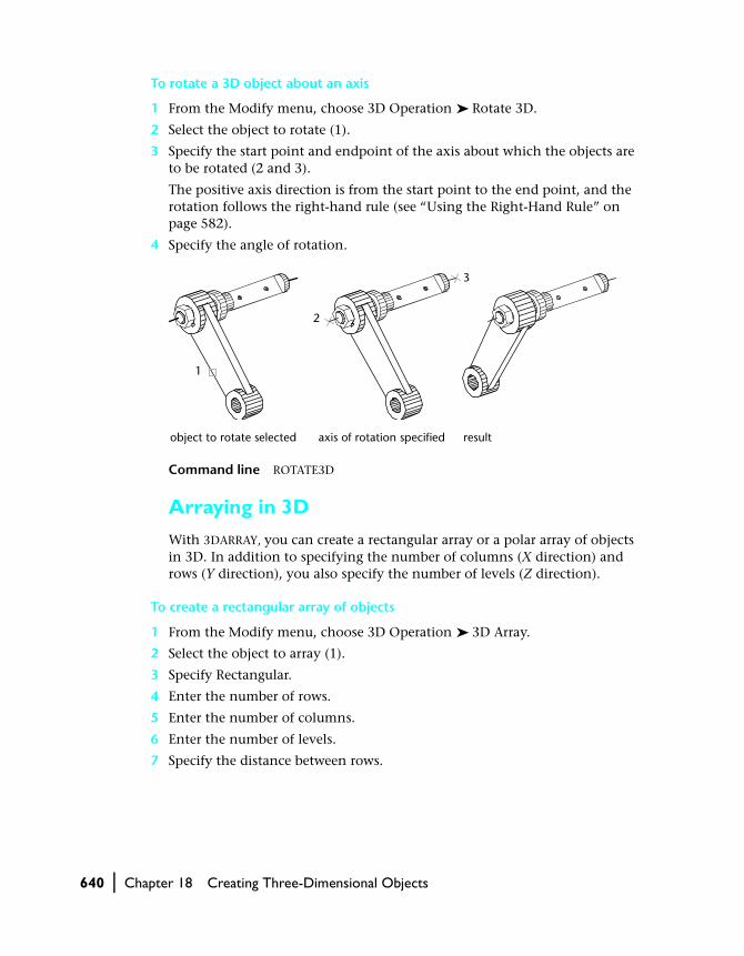
To rotate a 3D object about an axis
1 From the Modify menu, choose 3D Operation ➤ Rotate 3D.
2 Select the object to rotate (1).
3 Specify the start point and endpoint of the axis about which the objects are to be rotated (2 and 3).
The positive axis direction is from the start point to the end point, and the rotation follows the right-hand rule (see “Using the Right-Hand Rule” on page 582).
4 Specify the angle of rotation.
Command line ROTATE3D
Arraying in 3D
With 3DARRAY, you can create a rectangular array or a polar array of objects in 3D. In addition to specifying the number of columns (X direction) and rows (Y direction), you also specify the number of levels (Z direction).
To create a rectangular array of objects
1 From the Modify menu, choose 3D Operation ➤ 3D Array.
2 Select the object to array (1).
3 Specify Rectangular.
4 Enter the number of rows.
5 Enter the number of columns.
6 Enter the number of levels.
7 Specify the distance between rows.
object to rotate selected result
2
3
1
axis of rotation specified

Editing in 3D | 641
8 Specify the distance between columns.
9 Specify the distance between levels.
Command line 3DARRAY
To create a polar array of objects
1 From the Modify menu, choose 3D Operation ➤ 3D Array.
2 Select the object to array (1).
3 Specify Polar.
4 Enter the number of items to array.
5 Specify the angle that the arrayed objects are to fill.
6 Press ENTER to rotate the objects as they are arrayed, or enter n to retain their orientation.
7 Specify the start point and endpoint of the axis about which the objects are to be rotated (2 and 3).
Command line 3DARRAY
object to array selected result
1
2
3
1
642 | Chapter 18 Creating Three-Dimensional Objects
Mirroring in 3D
With MIRROR3D, you can mirror objects along a specified mirroring plane. The mirroring plane can be one of the following:
■ The plane of a planar object■ A plane parallel to the XY, YZ, or XZ plane of the current UCS that passes
through a point you select■ A plane defined by three points that you select
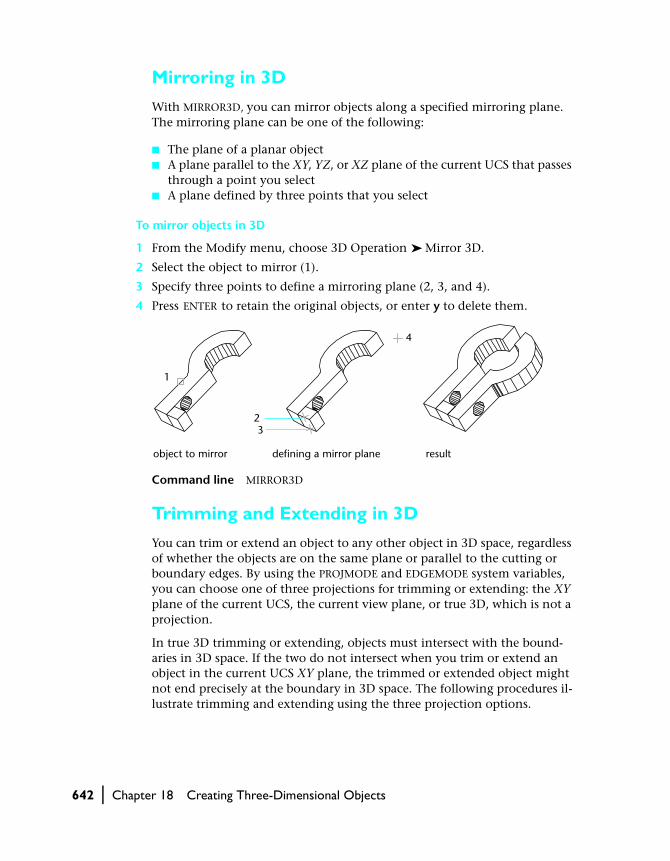
To mirror objects in 3D
1 From the Modify menu, choose 3D Operation ➤ Mirror 3D.
2 Select the object to mirror (1).
3 Specify three points to define a mirroring plane (2, 3, and 4).
4 Press ENTER to retain the original objects, or enter y to delete them.
Command line MIRROR3D
Trimming and Extending in 3D
You can trim or extend an object to any other object in 3D space, regardless of whether the objects are on the same plane or parallel to the cutting or boundary edges. By using the PROJMODE and EDGEMODE system variables, you can choose one of three projections for trimming or extending: the XY plane of the current UCS, the current view plane, or true 3D, which is not a projection.
In true 3D trimming or extending, objects must intersect with the bound-aries in 3D space. If the two do not intersect when you trim or extend an object in the current UCS XY plane, the trimmed or extended object might not end precisely at the boundary in 3D space. The following procedures il-lustrate trimming and extending using the three projection options.
object to mirror defining a mirror plane result
1
23
4

Editing in 3D | 643
To extend using an XY plane of the current UCS
1 From the Modify menu, choose Extend.
2 Select the boundary edge for extending (1).
3 Enter e (Edge).
4 Enter e (Extend).
5 Enter p (Project).
6 Enter u (UCS).
7 Select the object to extend (2).
Command line EXTEND
To trim using the current view plane
1 From the Modify menu, choose Trim.
2 Select the cutting edge for trimming (1).
3 Enter p (Project).
4 Enter v (View).
5 Select the object to trim (2).
Command line TRIM
1
2
2
1

644 | Chapter 18 Creating Three-Dimensional Objects
To trim using true 3D
1 From Modify menu, choose Trim.
2 Select the cutting edges to use for trimming (1 and 2).
3 Enter p (Project).
4 Enter n (None).
5 Select the object to trim (3 and 4).
Command line TRIM
Filleting in 3D
You can fillet coplanar objects with extrusion directions not parallel to the Z axis of the current UCS. AutoCAD determines the extrusion direction for the fillet arc in 3D space as follows.
For objects on the same plane with the same extrusion direction normal to that plane, the fillet arc is on that plane and has the same extrusion direction.
If the objects are on the same plane but have opposite or different extrusion directions, the fillet arc is placed on that object plane with an extrusion direction normal to the object plane and inclined towards the positive Z direction of the current UCS. For example, suppose two arcs, A and B, are on the same plane in 3D space but have opposite extrusion directions (0,0.5,0.8) and (0,–0.5,–0.8) relative to the current UCS. The fillet arc adopts the extru-sion direction (0,0.5,0.8).
1
3
2 4

Changing 3D Solids | 645
Changing 3D Solids
After creating a solid model, you can change its appearance by filleting, chamfering, sectioning, slicing, and separating.
You can also edit faces and edges on your solid model. You can easily remove blends created by FILLET or CHAMFER. You can change the color or copy a face or edge of a solid as a body, region, line, arc, circle, ellipse, or spline object. Imprinting geometry on existing solids creates new faces or merges redun-dant faces. Offsetting changes the faces relative to the original faces on the solid model, for example, making the diameter of a hole larger or smaller. Separating disjointed composite solids creates 3DSOLID objects. Shelling creates thin walls with a specified thickness.
Chamfering Solids
CHAMFER bevels the edges along the adjoining faces of a solid.
To chamfer a solid object
1 From the Modify menu, choose Chamfer.
2 Select the edge of the base surface to chamfer (1).
AutoCAD highlights one of two surfaces adjacent to the selected edge.
3 To select a different surface, enter n (Next), or press ENTER to use the current surface.
4 Specify the base surface distance.
The base surface distance is measured from the selected edge to a point on the base surface. The other surface distance is measured from the selected edge to a point on the adjacent surface.
5 Specify the adjacent surface distance.
Loop selects all edges around the base surface and Select Edge selects individ-ual edges.
6 Specify the edges to chamfer (2).
Command line CHAMFER
12
base surface selected edge to chamfer selected result

646 | Chapter 18 Creating Three-Dimensional Objects
Filleting Solids
With FILLET, you can add rounds and fillets to selected objects. The default method is specifying the fillet radius and then selecting the edges to fillet. Other methods specify individual measurements for each filleted edge and fillet a tangential series of edges.
To fillet a solid object
1 From the Modify menu, choose Fillet.
2 Select the edge of the solid to fillet (1).
3 Specify the fillet radius.
4 Select additional edges or press ENTER to fillet.
Command line FILLET
Sectioning Solids
With SECTION, you can create a cross section through a solid as a region or an anonymous block. The default method is specifying three points to define the plane. Other methods define the cross-sectional plane by another object, the current view, the Z axis, or the XY, YZ, or ZX plane. AutoCAD places the cross-sectional plane on the current layer.
To create a cross section of a solid
1 From the Draw menu, choose Solids ➤ Section.
2 Select the objects to cross-section.
3 Specify three points to define the cross-sectional plane.
edge to fillet selected result
1

Changing 3D Solids | 647
The first point defines the origin (0,0,0) of the cutting plane. The second point defines the X axis, and the third point defines the Y axis.
Command line SECTION
NOTE If you are applying hatching to the cross-sectional cutting plane, you must align the UCS with the cross-sectional cutting plane first.
Slicing Solids
With SLICE, you can create a new solid by cutting the existing solid and removing a specified side. You can retain one or both halves of the sliced solids. The sliced solids retain the layer and color properties of the original solids. The default method of slicing a solid is to specify three points that define the cutting plane and then select which side to retain. You can also define the cutting plane by using another object, the current view, the Z axis, or the XY, YZ, or ZX plane.
To slice a solid
1 From the Draw menu, choose Solids ➤ Slice.
2 Select the objects to slice.
cross-sectional cutting plane defined
cross section isolated andhatched for clarity
1
2
3
object selected and three points specified

648 | Chapter 18 Creating Three-Dimensional Objects
3 Specify three points to define the cutting plane.
The first point defines the origin (0,0,0) of the cutting plane. The second point defines the positive X axis, and the third point defines the positive Y axis.
4 Specify which side to retain, or enter b to retain both sides.
Command line SLICE
Editing Faces of 3D Solids
You can edit your solid object by extruding, moving, rotating, offsetting, tapering, deleting, copying it, or changing the color of the faces.
You can select individual faces on a 3D solid object or use one of the follow-ing AutoCAD selection methods:
■ Boundary set■ Crossing polygon■ Crossing window■ Fence
Boundary sets are sets of faces defined by a closed boundary, which consists of lines, circles, arcs, elliptical arcs, and spline curves. When defining a bound-ary set on a solid object, you first select an internal point on the solid, high-lighting the face. If you select the same point on the face again, AutoCAD highlights the adjoining face.
You can also select individual faces or edges with your pointing device or use a crossing window, an irregular shaped polygon, or a fence that selects faces or edges it passes through. See “Selecting Objects” on page 234.
one half of object retained
both halves retained
2
3
three points specified to define the cutting plane
1
Changing 3D Solids | 649
Extruding FacesYou can extrude planar faces along a path, or you can specify a height value and a tapered angle. Each face has a positive side, which is the side in the direction of the face’s normal (the current face you’re working on). Entering a positive value extrudes the face in its positive direction (usually outward); a negative value extrudes in the negative direction (usually inward).
Tapering the selected face with a positive angle tapers the face inward, and a negative angle tapers the face outward. The default angle, 0, extrudes the face perpendicular to its plane. If you specify a large taper angle or a long extrusion height, you can cause the face to taper to a point before it reaches the extrusion height; AutoCAD rejects the extrusion. Face extrusion along a path is based on a path curve (lines, circles, arcs, ellipses, elliptical arcs, polylines, or splines).
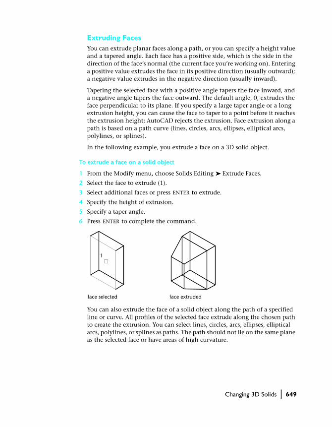
In the following example, you extrude a face on a 3D solid object.
To extrude a face on a solid object
1 From the Modify menu, choose Solids Editing ➤ Extrude Faces.
2 Select the face to extrude (1).
3 Select additional faces or press ENTER to extrude.
4 Specify the height of extrusion.
5 Specify a taper angle.
6 Press ENTER to complete the command.
You can also extrude the face of a solid object along the path of a specified line or curve. All profiles of the selected face extrude along the chosen path to create the extrusion. You can select lines, circles, arcs, ellipses, elliptical arcs, polylines, or splines as paths. The path should not lie on the same plane as the selected face or have areas of high curvature.
face selected face extruded
1

650 | Chapter 18 Creating Three-Dimensional Objects
To extrude a face along a path on a solid object
1 From the Modify menu, choose Solids Editing ➤ Extrude Faces.
2 Select the face to extrude (1).
3 Select additional faces or press ENTER to extrude.
4 Enter p (Path).
5 Select the object to use as the path (2).
6 Press ENTER to complete the command.
Command line SOLIDEDIT
Moving FacesYou can edit 3D solid objects by moving faces. AutoCAD moves the selected face(s) without changing their orientation. With AutoCAD 2000, moving holes from one location to another location in a 3D solid is easy. You can use Snap mode, coordinates, and object snaps to move the selected faces with precision.
In the following example, you move a drilled hole from one location to another location.
To move a face on a solid object
1 From the Modify menu, choose Solids Editing ➤ Move Faces.
2 Select the face to move (1).
3 Select additional faces or press ENTER to move the face.
4 Specify the base point for the move (2).
5 Specify the second point of displacement (3).
6 Press ENTER to complete the command.
face selected path selected
1
2
face extruded

Changing 3D Solids | 651
Command line SOLIDEDIT
Rotating FacesYou rotate selected faces or a collection of features on a solid, such as holes, by choosing a base point and a relative or absolute rotation angle. All 3D faces rotate about a specified axis. The current UCS and the ANGDIR system variable setting determine the direction of the rotation. You can specify the axis of rotation using two points; an object; the X, Y, or Z axis; or the Z direc-tion with respect to the line of sight in the current view.
In the following example, you rotate a drilled hole on a plate.
To rotate a face on a solid object
1 From the Modify menu, choose Solids Editing ➤ Rotate Faces.
2 Select the face to rotate (1).
3 Select additional faces or press ENTER to rotate.
4 Enter z for the axis point.
You can also specify the X or Y axis, two points (defines the axis of rotation), or axis by object (aligns the axis of revolution with an existing object) to define the axis point. The positive axis direction is from the start point to the endpoint, and the rotation follows the right-hand rule, unless it is reversed by the setting of the ANGDIR system variable.
5 Specify the angle of rotation.
6 Press ENTER to complete the command.
Command line SOLIDEDIT
Related SOLIDEDIT performs a similar operation to ROTATE3D.
face selected base point and secondpoint selected
face moved
1 23
face selected rotation point selected face rotated about Z axis 35°
1
2

652 | Chapter 18 Creating Three-Dimensional Objects
Offsetting FacesOn a 3D solid, you can uniformly offset faces by a specified distance. New faces are created by offsetting existing ones inside or outside at a specified distance from their original positions (offsetting works in the direction of the face’s normal or the positive side of the surface or face). For example, you can offset larger or smaller holes on a solid object. Specifying a positive value increases the size or volume of the solid; a negative value decreases the size or volume of the solid. You can also use a through point to specify the offset distance.
In the following example, you offset a drilled hole to change the size of the hole.
To offset a face on a solid object
1 From the Modify menu, choose Solids Editing ➤ Offset Faces.
2 Select the face to offset (1).
3 Select additional faces or press ENTER to offset.
4 Specify the offset distance.
5 Press ENTER to complete the command.
NOTE Holes inside a solid object offset smaller as the volume of the solid gets larger.
Command line SOLIDEDIT
Tapering FacesYou can taper faces with a draft angle along a vector direction. Tapering the selected face with a positive angle tapers the face inward, and a negative angle tapers the face outward. Avoid using extremely large tapered angles. If the angle is too large, the profile can taper to a point before it reaches the specified height, and AutoCAD rejects the tapering.
In the following example, you taper a hole to change its shape from a cylinder to a cone.
face selected face offset=1 face offset=–1
1

Changing 3D Solids | 653
To taper a face on a solid object
1 From the Modify menu, choose Solids Editing ➤ Taper Faces.
2 Select the face to taper (1).
3 Select additional faces or press ENTER to taper.
4 Specify the base point for the taper (2).
5 Specify the second point along an axis (3).
6 Specify the angle of the taper.
7 Press ENTER to complete the command.
Command line SOLIDEDIT
Deleting FacesYou can remove faces and fillets from a 3D solid object. For example, you can use SOLIDEDIT to remove drilled holes or fillets from your 3D solid object.
In the following example, you delete the fillets on a solid.
To delete a face on a solid object
1 From the Modify menu, choose Solids Editing ➤ Delete Faces.
2 Select the face to delete (1).
3 Select additional faces or press ENTER to delete.
4 Press ENTER to complete the command.
Command line SOLIDEDIT
face selected base point and second point selected
face tapered 10°
1
2
3
face selected face deleted
1

654 | Chapter 18 Creating Three-Dimensional Objects
Copying FacesYou can copy faces on a 3D solid object. AutoCAD copies selected faces as regions or bodies. If you specify two points, AutoCAD uses the first point as a base point and places a single copy relative to the base point. If you specify a single point, and then press ENTER, AutoCAD uses the original selection point as a base point and the next point as a point of displacement.
In the following example, you copy a face on a solid.
To copy a face on a solid object
1 From the Modify menu, choose Solids Editing ➤ Copy Faces.
2 Select the face to copy (1).
3 Select additional faces or press ENTER to copy.
4 Specify the base point for the copy (2).
5 Specify the second point of displacement (3).
6 Press ENTER to complete the command.
Command line SOLIDEDIT
NOTE Use EXTRUDE to extrude a copied face.
Coloring FacesYou can change the color of a face on a 3D solid object. You can choose a color from the seven standard colors or select a color from the Select Color dialog box. When specifying a color, you can enter the name of the color or an AutoCAD Color Index (ACI) number, an integer from 1 through 255. Set-ting a color on a face overrides the color setting for the layer on which the solid object resides. For information about assigning colors, see “Working with Colors” on page 331.
face selected base point and second point selected
face copied
1
2
3

Changing 3D Solids | 655
To change the color of a face on a solid object
1 From the Modify menu, choose Solids Editing ➤ Color Faces.
2 Select the face whose color you want to change.
3 Select additional faces or press ENTER.
4 In the Select Color dialog box, select a color and choose OK.
5 Press ENTER to complete the command.
Command line SOLIDEDIT
Editing Edges of 3D Solids
You can change the color of edges or copy individual edges on a 3D solid object. Colors are selected from the Select Color dialog box. All 3D solid edges are copied as lines, arcs, circles, ellipses, or spline objects.
Coloring EdgesYou can assign colors to individual edges on your 3D solid object. You can choose a color from the seven standard colors or select a color from the Select Color dialog box. When specifying a color, you can enter the name of the color or an ACI number, an integer from 1 through 255. Setting a color on an edge overrides the color setting for the layer on which the solid object resides. For information about assigning colors, see “Working with Colors” on page 331.
To change the color of an edge on a solid object
1 From the Modify menu, choose Solids Editing ➤ Color Edges.
2 Select the edge of a face to color.
3 Select additional edges or press ENTER.
4 In the Select Color dialog box, select a color and choose OK.
5 Press ENTER to complete the command.
Command line SOLIDEDIT
Copying EdgesYou can copy individual edges on a 3D solid object. All edges are copied as lines, arcs, circles, ellipses, or splines. If you specify two points, AutoCAD uses the first point as a base point and places a single copy relative to the base point. If you specify a single point, and then press ENTER, AutoCAD uses the original selection point as a base point and the next point as a point of displacement.

656 | Chapter 18 Creating Three-Dimensional Objects
In the following example, you copy an edge on a face.
To copy an edge on a solid object
1 From the Modify menu, choose Solids Editing ➤ Copy Edges.
2 Select the edge of the face to copy (1).
3 Select additional edges or press ENTER.
4 Specify the base point for the move (2).
5 Specify the second point of displacement (3).
6 Press ENTER to complete the command.
Command line SOLIDEDIT
Imprinting Solids
You can create new faces or 3D solids by imprinting arcs, circles, lines, 2D and 3D polylines, ellipses, splines, regions, bodies, and 3D solids. For example, if a circle intersects with a 3D solid, you can imprint the intersecting curves on the solid. You can delete or retain the original imprinted objects to be used for further editing. The imprinted object must intersect a face or faces on the selected solid in order for the imprinting to be successful.
To imprint a 3D solid object
1 From the Modify menu, choose Solids Editing ➤ Imprint.
2 Select the 3D solid object (1).
3 Select the object that you want to imprint (2).
4 Press ENTER to retain the original objects, or enter y to delete them.
edge selected base point and second point selected
edge copied
12
3

Changing 3D Solids | 657
5 Select additional objects to imprint or press ENTER.
6 Press ENTER to complete the command.
Command line SOLIDEDIT
Separating Solids
You can separate (take apart) composite solids. The composite 3D solid object cannot share a common area or volume. After separation of the 3D solid, the individual solids retain the layers and colors of the original. All nested 3D solid objects are separated into their simplest form.
To separate a 3D solid composite into individual solids
1 From the Modify menu, choose Solids Editing ➤ Separate.
2 Select the 3D solid object.
3 Press ENTER to complete the command.
Command line SOLIDEDIT
Shelling Solids
You can create a shell or a hollow thin wall with a specified thickness from your 3D solid object. AutoCAD creates new faces by offsetting existing ones inside or outside their original positions. AutoCAD treats continuously tan-gent faces as single faces when offsetting.
solid selected object selected object imprinted on solid
1
2

658 | Chapter 18 Creating Three-Dimensional Objects
In the following example, you create a shell in a cylinder.
To create a 3D solid shell
1 From the Modify menu, choose Solids Editing ➤ Shell.
2 Select the 3D solid object.
3 Select a face to be excluded from shelling (1).
4 Select additional faces to be excluded or press ENTER.
5 Specify the shell offset valve.
A positive offset value creates a shell in the positive face direction; a negative value creates a shell in the negative face direction.
6 Press ENTER to complete the command.
Command line SOLIDEDIT
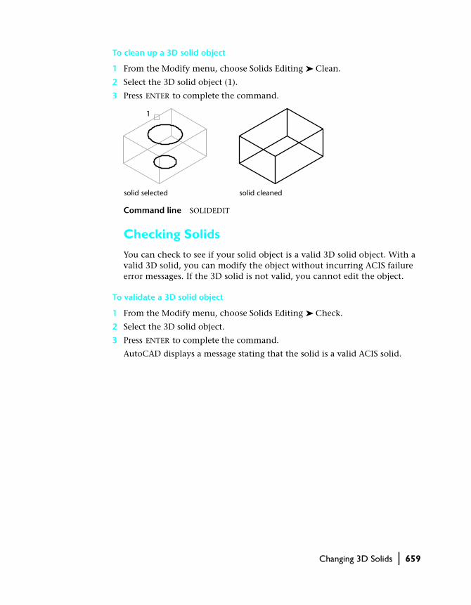
Cleaning Solids
You can remove edges or vertices if they share the same surface or vertex definition on either side of the edge or vertex. AutoCAD checks the body, faces, or edges on the solid object and merges adjacent faces that share the same surface. All redundant edges, imprinted as well as unused, on your 3D solid object are deleted.
face selected shell offset=0.5 shell offset=–0.5
1
Changing 3D Solids | 659
To clean up a 3D solid object
1 From the Modify menu, choose Solids Editing ➤ Clean.
2 Select the 3D solid object (1).
3 Press ENTER to complete the command.
Command line SOLIDEDIT
Checking Solids
You can check to see if your solid object is a valid 3D solid object. With a valid 3D solid, you can modify the object without incurring ACIS failure error messages. If the 3D solid is not valid, you cannot edit the object.
To validate a 3D solid object
1 From the Modify menu, choose Solids Editing ➤ Check.
2 Select the 3D solid object.
3 Press ENTER to complete the command.
AutoCAD displays a message stating that the solid is a valid ACIS solid.
solid selected solid cleaned
1