In-Space. Interspinous distraction through a mini-open, posterior, unilateral...
28
In-Space. Interspinous distraction through a mini-open, posterior, unilateral approach. Surgical Technique Posterior Approach This publication is not intended for distribution in the USA. Instruments and implants approved by the AO Foundation. PRODUCT OBSOLETED – 30th September 2017 DSEM/SPN/0915/0348(1)
Transcript of In-Space. Interspinous distraction through a mini-open, posterior, unilateral...

In-Space. Interspinous distractionthrough a mini-open, posterior, unilateralapproach.
Surgical TechniquePosterior Approach
This publication is not intended fordistribution in the USA.
Instruments and implants approved by the AO Foundation.
PRODUCT OBSOLETED – 30th September 2017
DSEM/SPN/0915/0348(1)

Image intensifier control
WarningThis description alone does not provide sufficient background for direct use of DePuy Synthes products. Instruction by a surgeon experienced in handling theseproducts is highly recommended.
Processing, Reprocessing, Care and MaintenanceFor general guidelines, function control and dismantling of multi-part instruments,as well as processing guidelines for implants, please contact your local salesrepresentative or refer to:http://emea.depuysynthes.com/hcp/reprocessing-care-maintenanceFor general information about reprocessing, care and maintenance of Synthesreusable devices, instrument trays and cases, please consult the ImportantInformation leaflet (SE_023827) or refer to:http://emea.depuysynthes.com/hcp/reprocessing-care-maintenance
Table of Contents
Introduction
Surgical Technique
Product Information
In-Space 2
Indications and Contraindications 4
Preoperative Planning 5
Patient Positioning 6
Surgical Technique for Posterior Unilateral Approach 7
Implant Removal 21
Implants 22
Instruments 23
In-Space Surgical Technique Posterior Approach DePuy Synthes 1

2
1
In-Space. Interspinous distractionthrough a mini-open, posterior, unilateralapproach.
In-Situ deployment of the anchorageWhen turning the screw (1), the implant closes and the wings (2) are deployed along the spinous processes
Intrinsic stability– The wings prevent ventral and lateral migration of
the implant– The intact supraspinous ligament prevents dorsal
displacement
2 DePuy Synthes In-Space Surgical Technique Posterior Approach
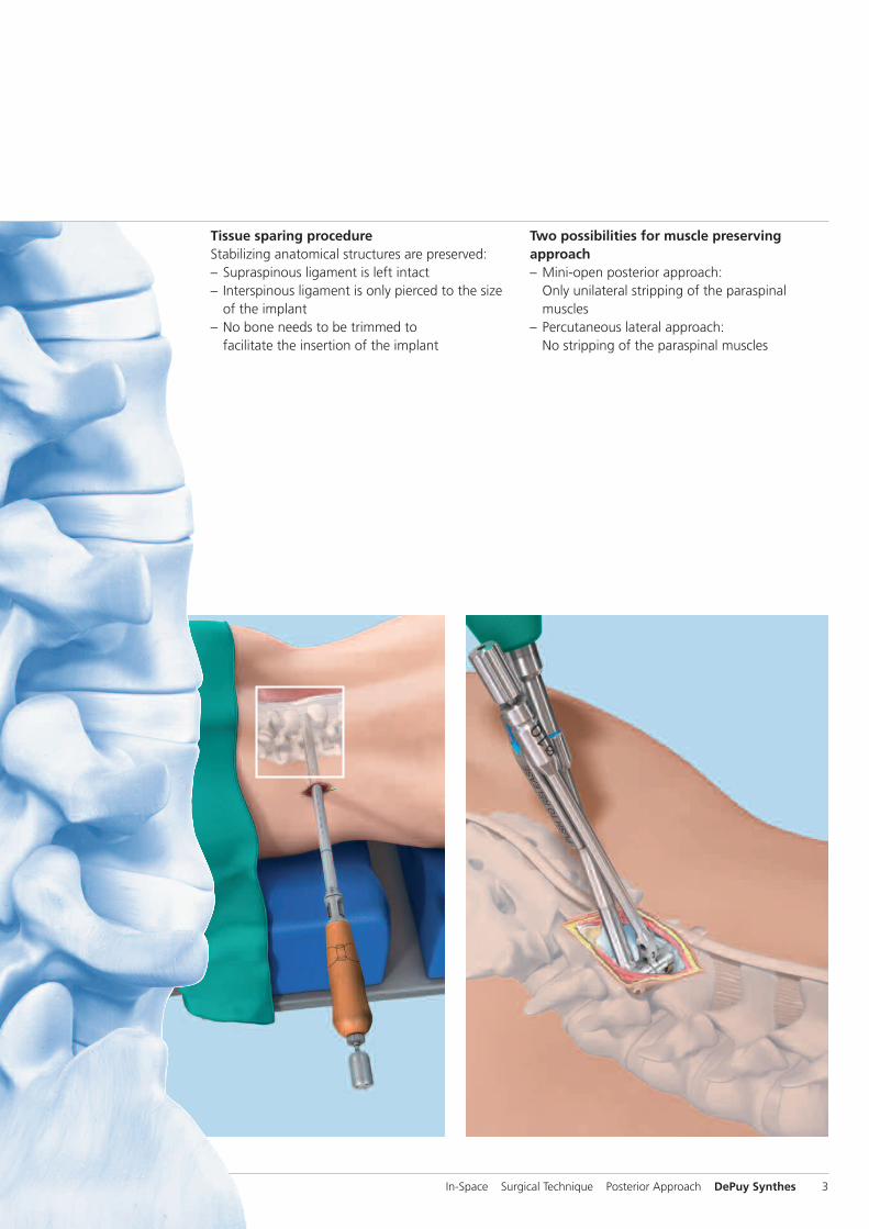
Tissue sparing procedureStabilizing anatomical structures are preserved:– Supraspinous ligament is left intact– Interspinous ligament is only pierced to the size
of the implant– No bone needs to be trimmed to
facilitate the insertion of the implant
Two possibilities for muscle preservingapproach– Mini-open posterior approach:
Only unilateral stripping of the paraspinal muscles
– Percutaneous lateral approach: No stripping of the paraspinal muscles
In-Space Surgical Technique Posterior Approach DePuy Synthes 3

Indications and Contraindications
Intended useIn-Space is intended to stop the segmental extension and todistract the interspinous space at a symptomatic level be-tween L1 to S1. In-Space acts as a space-holder and protectsmainly the posterior elements by– maintaining the foraminal height,– opening up the area of the spinal canal,– reducing stress on the facet joints and– relieving pressure on the posterior annulus.
IndicationsIn-Space can be implanted at one or two levels from L1 to S1for posterior approach (L1 to L5 for percutaneous approach).For implantation at L5/S1, the presence of a S1-spinousprocess of adequate size is a prerequisite to fully support theimplant.
Based on the intended use, In-Space can be used for the following indications:– Central, lateral and foraminal lumbar spinal stenosis with
leg, buttock or groin pain, which can be relieved duringflexion
– Soft disc protrusions with discogenic low back pain– Facet syndrome due to facet osteoarthritis– Degenerative spondylolisthesis up to grade I with
hyperlordotic curve– Degenerative Disc Disease (DDD) with retrolisthesis– Interspinous pain arising from Baastrup syndrome
(“kissing spines”)
In-Space can also be used as a temporary implant in conditions which require a temporary unloading of the discand/or facet joints.
Contraindications– Severe Osteoporosis– Conus/Cauda syndrome– Severe structural spinal stenosis lacking a dynamic
component– Fractures– Spondylolisis– Degenerative spondylolisthesis at index level of grade > I
according to Meyerding– Scoliotic deformity at index level– DDD with fixed retrolisthesis– Sequestrated disc herniation– Previous surgery at the operative level– Spinous process and/or lamina dysplasia– Infection– Morbid obesity (BMI >40)
Precaution: The stability of the In-Space relies on the pres-ence of the following structures:– Supraspinous ligament– Laminae– Spinous processes– Facet jointsComplete or significant removal of those structures may result in device migration.
4 DePuy Synthes In-Space Surgical Technique Posterior Approach

Preoperative Planning
In addition to routine preoperative investigations (X-rays APand lateral; MRI), flexion/extension views are strongly recommended. They provide a better understanding of theactive interspinous flexibility and can rule out gross trans-lational instability (e.g spondylolisthesis > grade I) or rigidretrolisthesis.
A preoperative CT reconstruction is recommended in the following situations:– Suspicion of spinous process and/or lamina dysplasia– At L5–S1 to control the presence of the S1 spinous process
In-Space Surgical Technique Posterior Approach DePuy Synthes 5

Patient Positioning
The use of a Wilson-like frame is recommended to decreasethe lordosis of the patient and to ensure that the abdomen isnot put under increased pressure. The table must be tiltableand radiolucent in both planes.
Place the patient in a comfortable prone position. It is advisable to tilt the pelvis by inclining the table at the level ofthe pelvis. This will intraoperatively increase the segmentalkyphosis and achieve natural distraction of the interspinousspace.
6 DePuy Synthes In-Space Surgical Technique Posterior Approach
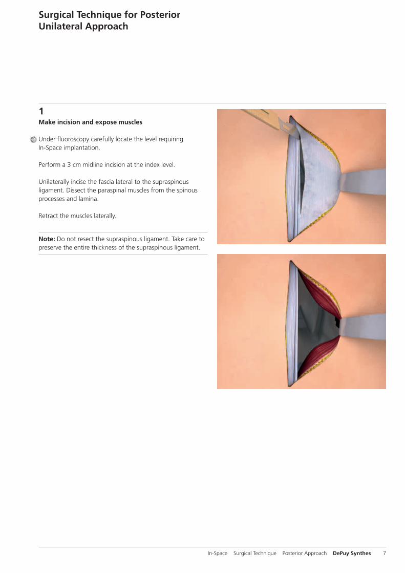
1Make incision and expose muscles
Under fluoroscopy carefully locate the level requiring In-Space implantation.
Perform a 3 cm midline incision at the index level.
Unilaterally incise the fascia lateral to the supraspinous ligament. Dissect the paraspinal muscles from the spinousprocesses and lamina.
Retract the muscles laterally.
Note: Do not resect the supraspinous ligament. Take care topreserve the entire thickness of the supraspinous ligament.
Surgical Technique for PosteriorUnilateral Approach
In-Space Surgical Technique Posterior Approach DePuy Synthes 7
Surgical Technique for Posterior Unilateral Approach
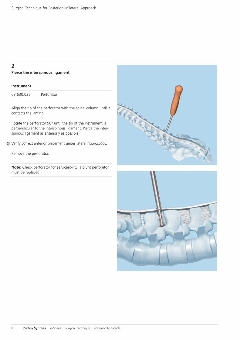
2Pierce the interspinous ligament
Instrument
03.630.025 Perforator
Align the tip of the perforator with the spinal column until itcontacts the lamina.
Rotate the perforator 90° until the tip of the instrument isperpendicular to the interspinous ligament. Pierce the inter-spinous ligament as anteriorly as possible.
Verify correct anterior placement under lateral fluoroscopy.
Remove the perforator.
Note: Check perforator for serviceability; a blunt perforatormust be replaced.
8 DePuy Synthes In-Space Surgical Technique Posterior Approach

3Choose appropriate implant size
Instruments
03.630.308 Trial Implant � 8 mm
03.630.310 Trial Implant � 10 mm
03.630.312 Trial Implant � 12 mm
03.630.314 Trial Implant � 14 mm
03.630.316 Trial Implant � 16 mm
Use the series of trial implants graduated in 2 mm incre-ments to define the appropriate implant size.
Insert the 8 mm trial implant into the pierced interspinousligament, as far anterior as possible. Repeat with sequentiallylarger trial implants until the desired distraction is achieved.The correct trial implant should completely fill the inter-spinous space and have a press fit contact to the cranial andcaudal rim of the inferior and superior spinous process.
Under lateral fluoroscopy, verify that the trial implant is positioned correctly on the top of the facets in the naturalconcavity of the spinous processes.
Also verify the distraction. Maximum admissible distraction isreached when the vertebral endplates are parallel to eachother.
Precaution– Avoid excessive distraction, as it can lead to loss of physio-
logical lordosis and/or result in postoperative pain due to overstretching of the joint capsules.
– If two implant sizes are possible, choose the smaller one in order to avoid over-distraction.
In-Space Surgical Technique Posterior Approach DePuy Synthes 9

03.630.026.002
03.630.026.001
Surgical Technique for Posterior Unilateral Approach
4Reassemble screwdriver
Instruments
03.630.026 Screwdriver, angled
03.630.053 Torque Limiter
After cleaning and sterilization the screwdriver needs to bereassembled prior to use.
1. Connect inner and outer screwdriver shaftSlide the inner shaft (03.630.026.002) with the gear wheelfirst into the outer screwdriver shaft (03.630.026.001) until itengages.
10 DePuy Synthes In-Space Surgical Technique Posterior Approach

1
2
3 ��
1
2
2. Mount screwdriver handleIntroduce the outer screwdriver shaft into the screwdriverhandle. Ensure that the protruding part of the screw-driver handle enters into the matching slot of the outerscrewdriver shaft (1).
Pull the two parts together. Under slight, constant pressuretighten the nut (2). The blue line on the handle must be inclose contact with the nut (3).
In-Space Surgical Technique Posterior Approach DePuy Synthes 11

��
��
Surgical Technique for Posterior Unilateral Approach
3. Mount torque limiter and deploy screwdriver insertMount the torque limiter on the screwdriver handle.
Fully deploy the screwdriver insert. To do so turn the knob of the torque limiter counterclockwise and check that thescrewdriver insert turns freely. Continue turning until the insert does not advance any further.
To ensure that the screwdriver insert is fully deployed intro-duce the screwdriver insert into the length indicator in theVario Case. It must at least reach the line marked with “OK”.
Note: Only in this position the screwdriver is long enough to engage into the screw of the implant.
Precaution: Repeated turning of the screwdriver insert in aclockwise direction can damage the instrument.
12 DePuy Synthes In-Space Surgical Technique Posterior Approach

1 2
3
4 5 ��
5Attach implant to implant holder
Instruments
03.630.021 Locking Screw
03.630.208 Implant Holder � 8 mm
03.630.210 Implant Holder � 10 mm
03.630.212 Implant Holder � 12 mm
03.630.214 Implant Holder � 14 mm
03.630.216 Implant Holder � 16 mm
Select the implant holder that corresponds to the implantsize defined in step 3.
Introduce the locking screw into the implant holder (1).
Select the implant that corresponds to the previously definedimplant size.
Introduce the implant into the holder with the slots of theimplant pointing into the direction of the implant holder. Ensure that the slots of the implant engage properly with thenotches of the implant holder (2).
Ensure that the implant is inserted to the full depth of theimplant holder.
Turn the locking screw to close the implant holder (3).
Verify that the implant is correctly attached. The lines on the shovels of the implant holder must be in line with the proximal corpus of the implant (4). Ensure that the shovels of the implant holder do not cover and block thewings of the implant for later deployment (5).
In-Space Surgical Technique Posterior Approach DePuy Synthes 13

1 2
3 4
5a
6
30°
�� 5b
6Attach implant holder to screwdriver
Instrument
314.070 Screwdriver, hexagonal, small
Connect the back of the implant holder to the screwdriverhead in an angle of approximately 30° (1). To do so, ensurethat the black line on the back of the implant holder isaligned with the black line at the side of the screwdriverhead (2).
Overcome the spring resistance of the screwdriver insert by firmly pressing the implant holder against the screwdriverhead (3).
While maintaining the pressure, close the bayonet lock by rotating the implant holder towards the shaft of the screw-driver and click it into the corresponding hole of the screw-driver (4).
Verify that the two instruments are correctly connected. Theback of the implant holder must lay flush on the screwdriver(5a, 5b).
Insert the hexagonal screwdriver into the head of the lockingscrew and finally tighten the locking screw (6).
Note: If resistance is felt when rotating the implant holder,do not apply force. Otherwise the bayoneted lock will bedamaged. Check that the implant holder has been correctlyconnected to the screwdriver insert and rotate again.
Surgical Technique for Posterior Unilateral Approach
14 DePuy Synthes In-Space Surgical Technique Posterior Approach

1
2
3
7Insert implant
Technique tip on implant insertion: When working withsmall incisions, the space available for the insertion instru-ments can be critical. Approaching the interspinous space directly perpendicular to the midline might be difficult. It isrecommended to apply the modified insertion technique described below.
Remove the trial implant as late as possible after the implantis correctly mounted on the implant holder.
Facing from caudal to cranial align the implant holder withthe spinal column. Orient the tip of the implant holder towards the perforated hole of the interspinous ligament (1).
While rotating the instrument in perpendicular direction simultaneously slide its proximal end under the fascia (2).
Slide the construct in its final position (3).
Under lateral fluoroscopy verify that the instruments are positioned on top of the facets in the natural concavity ofthe spinous processes. Re-correct if necessary.
Orient the shaft of the screwdriver parallel to the 2 rims of the spinous processes and perpendicular to the posteriorcontour of the facets.
In-Space Surgical Technique Posterior Approach DePuy Synthes 15

Under AP fluoroscopy place the instruments in their correctinsertion depth. Visualize the 2 holes on the upper shovel ofthe implant holder. They define the midline of the In-Spaceimplant in its closed end position and have to be alignedwith the spinous processes.
Notes– Correct positioning of the insertion instruments is crucial.
Their final position defines the final implant position. Oncethe wings of the implant are deployed, the position of the implant cannot be corrected anymore.
– The screwdriver shaft has an angulation of 102° in order toenhance the visualization of the interspinous space. Do notplace the screwdriver shaft perpendicular to the coronalplane, since this would end in an oblique placement of theimplant.
Surgical Technique for Posterior Unilateral Approach
16 DePuy Synthes In-Space Surgical Technique Posterior Approach

8Deploy wings
Turn the knob of the screwdriver clockwise to deploy thewings of the implant.
When the wings are fully deployed, a distinctive increase in resistance is felt and the screwdriver reaches its ultimatetorque.
Verify proper and complete deployment of the wings. Use AP fluoroscopy to assess the contra-lateral side.
In-Space Surgical Technique Posterior Approach DePuy Synthes 17
1 2
3 4
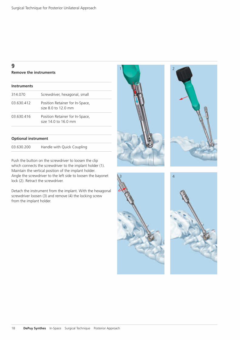
9Remove the instruments
Instruments
314.070 Screwdriver, hexagonal, small
03.630.412 Position Retainer for In-Space, size 8.0 to 12.0 mm
03.630.416 Position Retainer for In-Space, size 14.0 to 16.0 mm
Optional instrument
03.630.200 Handle with Quick Coupling
Push the button on the screwdriver to loosen the clip which connects the screwdriver to the implant holder (1).Maintain the vertical position of the implant holder. Angle the screwdriver to the left side to loosen the bayonetlock (2). Retract the screwdriver.
Detach the instrument from the implant. With the hexagonalscrewdriver loosen (3) and remove (4) the locking screw from the implant holder.
Surgical Technique for Posterior Unilateral Approach
18 DePuy Synthes In-Space Surgical Technique Posterior Approach

6 7
8
5Attach the handle with quick coupling to the implant holder.
Choose the correct sized position retainer. Introduce it from the contra-lateral side to avoid conflict of space withthe implant holder (5). The “ratchet” must grip the 2 ipsi -lateral wings (6). Remove the implant holder while main -taining the implant in its original position.
Take care to retract the implant holder strictly in lateral direction until the lower shovel of the implant holder comesout of the interspinous space (7).
Only then rotate the handle towards the midline to liberatethe upper shovel of the implant holder from the interspinousspace (8).
Precaution: Do not apply rotational movements on the im-plant holder as long as the lower shovel is still contained inthe interspinous space. This could cause damage to the im-plant wings.
In-Space Surgical Technique Posterior Approach DePuy Synthes 19
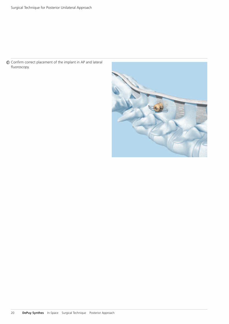
Confirm correct placement of the implant in AP and lateralfluoroscopy.
Surgical Technique for Posterior Unilateral Approach
20 DePuy Synthes In-Space Surgical Technique Posterior Approach

Implant Removal
The implant can be removed through a conventional posterior approach.
First, cut the wings and then remove the implant by pushingit to the side, displacing it from between the spinousprocesses.
In-Space Surgical Technique Posterior Approach DePuy Synthes 21
Lateralbending
Axial rotation
Extension
Flexion
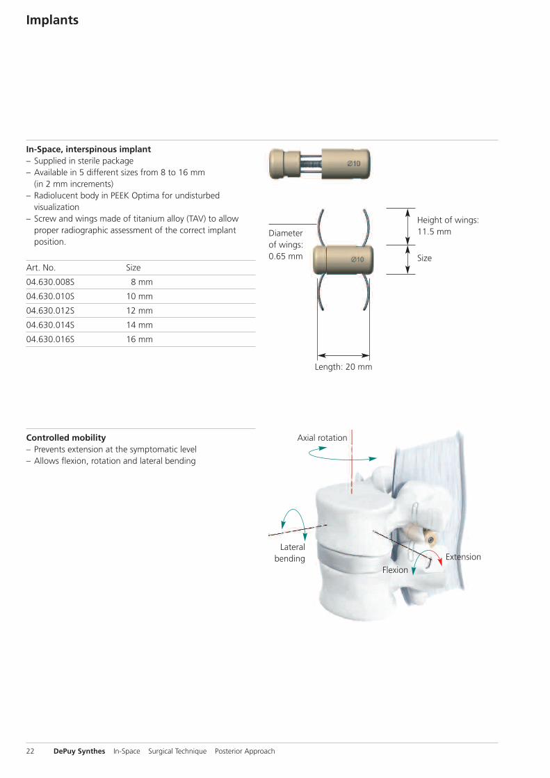
In-Space, interspinous implant – Supplied in sterile package– Available in 5 different sizes from 8 to 16 mm
(in 2 mm increments)– Radiolucent body in PEEK Optima for undisturbed
visualization– Screw and wings made of titanium alloy (TAV) to allow
proper radiographic assessment of the correct implant position.
Art. No. Size
04.630.008S 8 mm
04.630.010S 10 mm
04.630.012S 12 mm
04.630.014S 14 mm
04.630.016S 16 mm
Size
Height of wings:11.5 mm
Length: 20 mm
Diameterof wings:0.65 mm
Controlled mobility– Prevents extension at the symptomatic level– Allows flexion, rotation and lateral bending
Implants
22 DePuy Synthes In-Space Surgical Technique Posterior Approach

Instruments
03.630.025 Perforator, for Posterior Insertion of In-Space
Used to pierce the interspinous ligament.
03.630.026 Screwdriver, angled, for Posterior Insertion of In-Space
Allows in-situ deployment of the implant’s wings.
03.630.021 Locking Screw, for Implant Holders Nos. 03.630.208 to 03.630.216
Used to clamp the implant on the implant holder.
03.630.208 Implant Holder � 8 mm03.630.210 Implant Holder � 10 mm03.630.212 Implant Holder � 12 mm03.630.214 Implant Holder � 14 mm03.630.216 Implant Holder � 16 mm
Used to hold the implant while introducing it into the interspinous space.
03.630.308 Trial Implant � 8 mm, for PosteriorInsertion of In-Space
03.630.310 Trial Implant � 10 mm, for Posterior Insertion of In-Space03.630.312 Trial Implant � 12 mm, for Posterior Insertion of In-Space03.630.314 Trial Implant � 14 mm, for Posterior Insertion of In-Space03.630.316 Trial Implant � 16 mm, for Posterior Insertion of In-Space
Used to determine the appropriate size of the implant.
In-Space Surgical Technique Posterior Approach DePuy Synthes 23

Instruments
03.630.200 Handle with Quick Coupling, for In-Space Implant Holders 03.630.208–216
Used in combination with the implant holders to facilitate their removal.
03.630.412 Position Retainer for In-Space size 8.0 to 12.0 mm
03.630.416 Position Retainer for In-Space size 14.0 to 16.0 mm
Used to maintain the implants in position while removing the implant holders.
314.070 Screwdriver, hexagonal, small, � 2.5 mm, with Groove
Used for final tightening of the locking screw.
03.630.053 Torque Limiter, for In-Space Screwdriver No. 03.630.026
Allows controlled deployment of the implant’s wings.
24 DePuy Synthes In-Space Surgical Technique Posterior Approach


Synthes GmbHEimattstrasse 34436 OberdorfSwitzerlandTel: +41 61 965 61 11Fax: +41 61 965 66 00www.depuysynthes.com 0123 ©
DeP
uy Syn
thes
Spine
, a division of Syn
thes
GmbH
. 201
5.
All rig
hts rese
rved
. 036.000.046
DSEM/SPN
/0915/0348 11/15
This publication is not intended for distribution in the USA.
Not all products are currently available in all markets.
All surgical techniques are available as PDF files at www.depuysynthes.com/ifu