In Salah CO2 Storage Project: Monitoring Experience workshop_june 2012... · RGB 250, 166, 26 13,...
30
In Salah CO 2 Storage Project: Monitoring Experience Allan Mathieson JIP Programme Manager CGS Conference – Ankara, Turkey, 14 June 2012
Transcript of In Salah CO2 Storage Project: Monitoring Experience workshop_june 2012... · RGB 250, 166, 26 13,...

In Salah CO2 Storage Project:
Monitoring Experience
Allan Mathieson JIP Programme Manager
CGS Conference – Ankara, Turkey, 14 June 2012

Primary colours
RGB
250, 166, 26
13, 145, 193
128, 195, 66
Secondary
Colours RGB
247, 218, 0
184, 47, 38
114, 15, 16
60, 26, 22
174, 197, 231
ISG CO2 JIP Phase 1 Lessons 2
Agenda
In Salah CCS: Context & Overview
In Salah JIP Phase 1 Lessons:
1. Site Selection
2. Project Boundaries and Accounting
3. Monitoring
4. Risk Assessment
5. Informing Regulation
Summary & Discussion

Primary colours
RGB
250, 166, 26
13, 145, 193
128, 195, 66
Secondary
Colours RGB
247, 218, 0
184, 47, 38
114, 15, 16
60, 26, 22
174, 197, 231
ISG CO2 JIP Phase 1 Lessons 3
Krechba
Teg
Reg
Garet elBefinat Hassi Moumene
In Salah
Gour Mahmoud
Proposed ISG Pipeline
REB
Hassi BirRekaiz
Hassi Messaoud
Hassi R’Mel
Tiguentourine (BP)
02151093
Algiers
Tangiers
Lisbon
Cordoba
Cartagena
M O R O C C O
A L G E R I A
S P A I N
L I B Y A
MAURITANIAM A L I
SkikdaTunis
N I G E R
In Salah Gas
Project
• Industrial Scale Demonstration of CO2 Geological Storage (Conventional Capture) • Storage Formation is common in Europe, USA & China • Started Storage in August 2004 at 1mmtpa. 3.86 mmt CO2 stored at end 2011 • $100mm Incremental Cost for Storage. No commercial benefit • Test-bed for CO2 Monitoring Technologies: $30mm Research Project
Project Summary
In Salah CCS Project: Overview

Primary colours
RGB
250, 166, 26
13, 145, 193
128, 195, 66
Secondary
Colours RGB
247, 218, 0
184, 47, 38
114, 15, 16
60, 26, 22
174, 197, 231
ISG CO2 JIP Phase 1 Lessons 4
Agenda
In Salah CCS: Context & Overview
In Salah JIP Phase 1 Lessons:
1. Site Selection
2. Project Boundaries and Accounting
3. Monitoring
4. Risk Assessment
5. Informing Regulation
Summary & Discussion

Primary colours
RGB
250, 166, 26
13, 145, 193
128, 195, 66
Secondary
Colours RGB
247, 218, 0
184, 47, 38
114, 15, 16
60, 26, 22
174, 197, 231
ISG CO2 JIP Phase 1 Lessons 5
Risk-Management Process (EU CCS Directive)
( Ref: CO2QUALSTORE, DNV 2009 )

Primary colours
RGB
250, 166, 26
13, 145, 193
128, 195, 66
Secondary
Colours RGB
247, 218, 0
184, 47, 38
114, 15, 16
60, 26, 22
174, 197, 231
ISG CO2 JIP Phase 1 Lessons 6
CO2 Storage: Generic Risk Profile
We
Are
Here
Maximum Risk (Developer)
Maximum Risk (Nation)
Risk Profile of a CGS Project
Time
Ris
k
Site
Selection
and
Develop-
ment
Operation
(Injection)
Closure Post-Closure
M&V
QRA
Nation/
Landowner
Nation/
Landowner Operator Stewardship
Project
Phase
Monitoring
Baseline
Data
Acquisition
and Initial
QRA
M&V
QRA
M&V
QRA
Screen,
Assess,
Select,
Design Construct Operate Close
Maximum Risk:
National Stewardship
Maximum Risk:
Developer Stewardship
Primary colours
RGB
250, 166, 26
13, 145, 193
128, 195, 66
Secondary
Colours RGB
247, 218, 0
184, 47, 38
114, 15, 16
60, 26, 22
174, 197, 231
ISG CO2 JIP Phase 1 Lessons 7
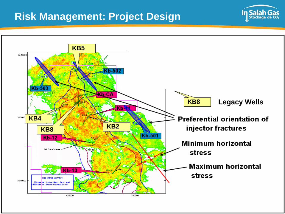
Risk Management: Project Design
KB5
KB4
KB8 KB2
KB8 Legacy Wells

Primary colours
RGB
250, 166, 26
13, 145, 193
128, 195, 66
Secondary
Colours RGB
247, 218, 0
184, 47, 38
114, 15, 16
60, 26, 22
174, 197, 231
ISG CO2 JIP Phase 1 Lessons 8
Site Selection and Operation
Quantified Risk Assessments (QRA) should be used to manage seepage risk
– During site selection, project design and updated periodically during operation
– Several methodologies are available
Monitoring should be in the Field Development Plan (FDP) and Field Operations
– Designed around an early assessment of seepage risks
Initial appraisal and development of a CO2 storage project should collect a
comprehensive set of baseline data – To adequately characterise the Storage Complex / Area of Review
At In Salah:
Baseline data acquisition should have begun earlier & been more-comprehensive
Top Three risks were: Integrity of wells and caprock, plus CO2 migration direction

Primary colours
RGB
250, 166, 26
13, 145, 193
128, 195, 66
Secondary
Colours RGB
247, 218, 0
184, 47, 38
114, 15, 16
60, 26, 22
174, 197, 231
ISG CO2 JIP Phase 1 Lessons 9
Agenda
In Salah CCS: Context & Overview
In Salah JIP Phase 1 Lessons:
1. Site Selection
2. Project Boundaries and Accounting
3. Monitoring
4. Risk Assessment
5. Informing Regulation
Summary & Discussion
Primary colours
RGB
250, 166, 26
13, 145, 193
128, 195, 66
Secondary
Colours RGB
247, 218, 0
184, 47, 38
114, 15, 16
60, 26, 22
174, 197, 231
ISG CO2 JIP Phase 1 Lessons 10
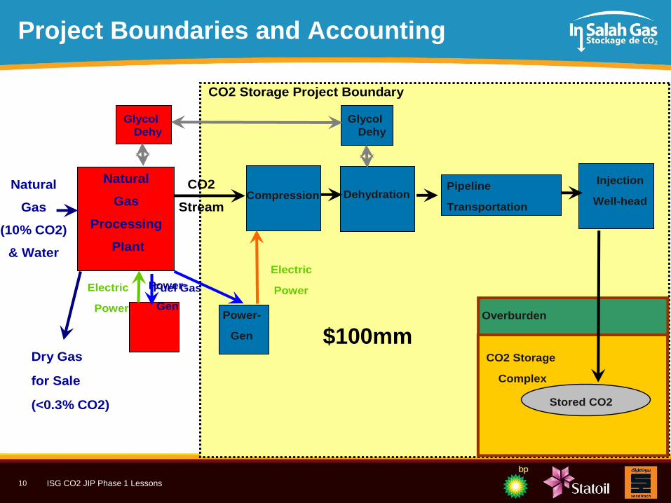
Project Boundaries and Accounting
Natural
Gas
(10% CO2)
& Water
Power-
GenPower-
Gen
Compression DehydrationPipeline
Transportation
Injection
Well-head
Dry Gas
for Sale
(<0.3% CO2)
Natural
Gas
Processing
Plant
CO2
Stream
Fuel Gas
Electric
PowerElectric
PowerOverburden
Stored CO2
CO2 Storage
Complex
CO2 Storage Project Boundary
Glycol
Dehy
Glycol
Dehy
$100mm

Primary colours
RGB
250, 166, 26
13, 145, 193
128, 195, 66
Secondary
Colours RGB
247, 218, 0
184, 47, 38
114, 15, 16
60, 26, 22
174, 197, 231
ISG CO2 JIP Phase 1 Lessons 11
Agenda
In Salah CCS: Context & Overview
In Salah JIP Phase 1 Lessons:
1. Site Selection
2. Project Boundaries and Accounting
3. Monitoring
4. Risk Assessment
5. Informing Regulation
Summary & Discussion

Primary colours
RGB
250, 166, 26
13, 145, 193
128, 195, 66
Secondary
Colours RGB
247, 218, 0
184, 47, 38
114, 15, 16
60, 26, 22
174, 197, 231
ISG CO2 JIP Phase 1 Lessons 12
Benefit
Cost Low High
Low
High
Satellite
Imaging
Geochemistry
Micro-
seismic
Flowmeters
Wellhead
monitoring
4D gravity Tracers
Dynamic
Modelling
Wellbore
sampling
Annulus
Sampling 4D VSP
Cement
CO2 work
4D
Seismic
Tiltmeters
Cross-well
EM
Geomechanics
Logging
Surface EM
Aquifer
studies
Microbiology
Surface flux Observation
Wells
Airborne
Flux
Park
Focussed
Application Just Do It
Consider Key
To be tested
Water
Chemistry
Monitoring Technologies: Evaluation
Soil Gas
Primary colours
RGB
250, 166, 26
13, 145, 193
128, 195, 66
Secondary
Colours RGB
247, 218, 0
184, 47, 38
114, 15, 16
60, 26, 22
174, 197, 231
ISG CO2 JIP Phase 1 Lessons
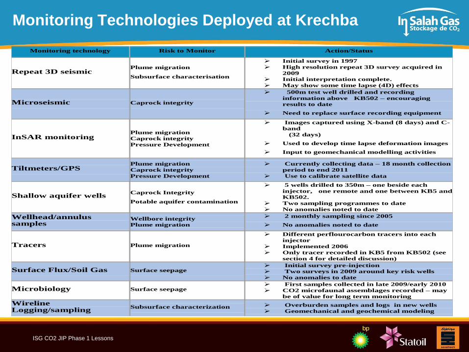
Monitoring Technologies Deployed at Krechba
Monitoring technology Risk to Monitor Action/Status
Repeat 3D seismic Plume migration
Subsurface characterisation
Initial survey in 1997
High resolution repeat 3D survey acquired in
2009
Initial interpretation complete.
May show some time lapse (4D) effects
Microseismic Caprock integrity
500m test well drilled and recording
information above KB502 – encouraging
results to date
Need to replace surface recording equipment
InSAR monitoring Plume migration
Caprock integrity
Pressure Development
Images captured using X-band (8 days) and C-
band
(32 days)
Used to develop time lapse deformation images
Input to geomechanical modelling activities
Tiltmeters/GPS Plume migration
Caprock integrity
Pressure Development
Currently collecting data – 18 month collection
period to end 2011
Use to calibrate satellite data
Shallow aquifer wells Caprock Integrity
Potable aquifer contamination
5 wells drilled to 350m – one beside each
injector, one remote and one between KB5 and
KB502.
Two sampling programmes to date
No anomalies noted to date
Wellhead/annulus samples
Wellbore integrity
Plume migration
2 monthly sampling since 2005
No anomalies noted to date
Tracers Plume migration
Different perflourocarbon tracers into each
injector
Implemented 2006
Only tracer recorded in KB5 from KB502 (see
section 4 for detailed discussion)
Surface Flux/Soil Gas Surface seepage Initial survey pre-injection
Two surveys in 2009 around key risk wells
No anomalies to date
Microbiology Surface seepage First samples collected in late 2009/early 2010
CO2 microfaunal assemblages recorded – may
be of value for long term monitoring
Wireline Logging/sampling
Subsurface characterization Overburden samples and logs in new wells
Geomechanical and geochemical modeling

Primary colours
RGB
250, 166, 26
13, 145, 193
128, 195, 66
Secondary
Colours RGB
247, 218, 0
184, 47, 38
114, 15, 16
60, 26, 22
174, 197, 231
ISG CO2 JIP Phase 1 Lessons 14
Monitoring: Low-cost Options
Low-cost technologies can be very effective CO2 monitoring tools
At In Salah: these included: – Wellhead (pressure & flowrate) annulus monitoring (including tracers)
– Soil-gas surveys, permanent soil-gas detectors, microbiological sampling
– Gas surface flux (using laser surveys),
– Shallow aquifer sampling
CPF
BdV
Bar-A
Bar-BKb-502Kb-602
Kb-601Kb-5
Kb-503
Airstrip
Kb-4
Kb-501
Kb-7
CPF
BdV
Bar-A
Bar-BKb-502Kb-602
Kb-601Kb-5
Kb-503
Airstrip
Kb-4
Kb-501
Kb-7

Primary colours
RGB
250, 166, 26
13, 145, 193
128, 195, 66
Secondary
Colours RGB
247, 218, 0
184, 47, 38
114, 15, 16
60, 26, 22
174, 197, 231
ISG CO2 JIP Phase 1 Lessons 15
Monitoring: Seismic
Acquisition of a high-quality, pre-injection 3D seismic baseline is a vital
– for characterising the overburden and the injection horizon
The value of subsequent (time-lapse) 3D surveys will depend on rock quality and the
density difference between in-situ fluids and the injected CO2
A comprehensive understanding of the interaction of rock-physics, fluids and
fractures is required to adequately model Seismic responses to CO2 injection
At In Salah:
– 4D may never be a good option for CO2 monitoring (due to poor rock quality and
insufficient density contrast between fluids)
Primary colours
RGB
250, 166, 26
13, 145, 193
128, 195, 66
Secondary
Colours RGB
247, 218, 0
184, 47, 38
114, 15, 16
60, 26, 22
174, 197, 231
ISG CO2 JIP Phase 1 Lessons 16
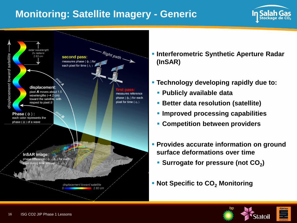
Monitoring: Satellite Imagery - Generic
Interferometric Synthetic Aperture Radar
(InSAR)
Technology developing rapidly due to:
Publicly available data
Better data resolution (satellite)
Improved processing capabilities
Competition between providers
Provides accurate information on ground
surface deformations over time
Surrogate for pressure (not CO2)
Not Specific to CO2 Monitoring

Primary colours
RGB
250, 166, 26
13, 145, 193
128, 195, 66
Secondary
Colours RGB
247, 218, 0
184, 47, 38
114, 15, 16
60, 26, 22
174, 197, 231
ISG CO2 JIP Phase 1 Lessons 17
Monitoring: Satellite Imagery - At In Salah
InSAR (combined with geo-mechanical modelling), has been key to understanding the
subsurface distribution of pressure fronts and CO2 plumes
– Benchmarked by CO2 observation at KB5
– Significantly influenced the 2009 seismic survey and Quantified Risk Assessment
– Data is available since 2003 (pre-injection), C-Band (Envisat and Radarsat2)
– Use of new X-Band data allows observation every 8 days.
– Inversion using diversity of research partners and techniques
– Used as an observation constraint for geo-mechanical modelling
2005 2007 2009

Primary colours
RGB
250, 166, 26
13, 145, 193
128, 195, 66
Secondary
Colours RGB
247, 218, 0
184, 47, 38
114, 15, 16
60, 26, 22
174, 197, 231
ISG CO2 JIP Phase 1 Lessons 18
Agenda
In Salah CCS: Context & Overview
In Salah JIP Phase 1 Lessons:
1. Site Selection
2. Project Boundaries and Accounting
3. Monitoring
4. Risk Assessment
5. Informing Regulation
Summary & Discussion

Primary colours
RGB
250, 166, 26
13, 145, 193
128, 195, 66
Secondary
Colours RGB
247, 218, 0
184, 47, 38
114, 15, 16
60, 26, 22
174, 197, 231
ISG CO2 JIP Phase 1 Lessons 19
Risk Assessment
Quantified Risk Assessment (QRA) is an invaluable tool to understand, manage and communicate the performance of a CO2 storage operation
– Should be periodically repeated over the life of a CO2 storage project
Several methodologies are available
At In Salah:
– Pre-injection risk assessment highlighted the key risks and informed the baseline data acquisition programme and early monitoring
– Evaluated QRA methodologies: CCPCF, URS, FEP, Oxand
– The QRA is updated regularly and used to inform injection and monitoring strategies

Primary colours
RGB
250, 166, 26
13, 145, 193
128, 195, 66
Secondary
Colours RGB
247, 218, 0
184, 47, 38
114, 15, 16
60, 26, 22
174, 197, 231
ISG CO2 JIP Phase 1 Lessons 20
In Salah Quantified Risk Assessment
In Salah Containment Risk
0.001
0.01
0.1
1
10
100
1000
10000
100000
1000000
Pe
rme
ab
le z
on
es
in s
ea
l
Lea
kag
e -
Un
de
tecte
d f
ault
Lea
kag
e -
We
lls
Re
gio
na
l-sca
le
overp
ressu
rizatio
n
Loca
l-sca
le
overp
ressu
rizatio
n
Exce
ed
ing
sp
illp
oin
t
Ea
rth
qu
ake
indu
ced
fra
ctu
res
Mig
ratio
n d
ire
ction
Tota
l C
onta
inm
en
t
Ris
k
Ev
en
t R
isk Q
uo
tie
nt
Pessimistic(CL95%)
Planning(CL80%)
Optimistic(CL50%)
AcceptableProjectContainmentRisk (RQ)
AcceptableSingle EventContainmentRisk (RQ)
1
2

Primary colours
RGB
250, 166, 26
13, 145, 193
128, 195, 66
Secondary
Colours RGB
247, 218, 0
184, 47, 38
114, 15, 16
60, 26, 22
174, 197, 231
ISG CO2 JIP Phase 1 Lessons 21
Key Risk #1: Migration Direction Risk
Expected
N S
Fractured zone
in seal
Fracture permeability
Incorrectly identified
saddle point
Flow barrier
10 July 2010
(MDA & Pinnacle)

Primary colours
RGB
250, 166, 26
13, 145, 193
128, 195, 66
Secondary
Colours RGB
247, 218, 0
184, 47, 38
114, 15, 16
60, 26, 22
174, 197, 231
ISG CO2 JIP Phase 1 Lessons 22
Key Risk #2: Legacy Wells
KB5
KB4
KB8 KB2
KB8 Legacy Wells
Primary colours
RGB
250, 166, 26
13, 145, 193
128, 195, 66
Secondary
Colours RGB
247, 218, 0
184, 47, 38
114, 15, 16
60, 26, 22
174, 197, 231
ISG CO2 JIP Phase 1 Lessons 23
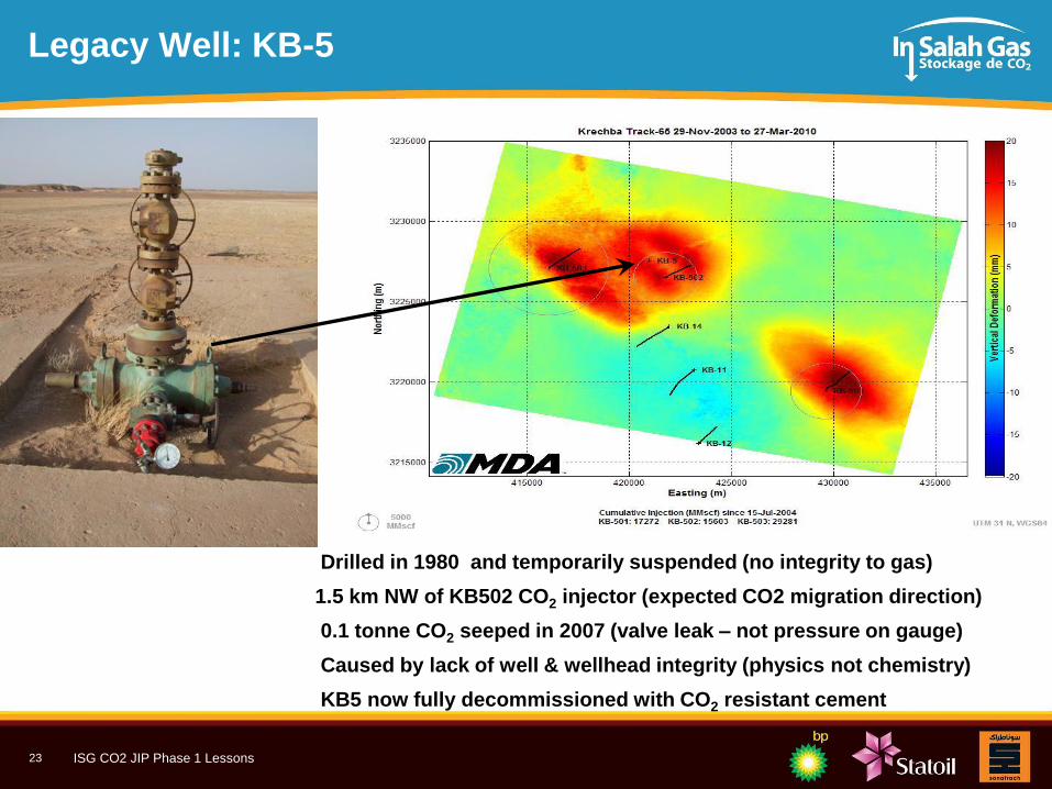
Legacy Well: KB-5
• Drilled in 1980 and temporarily suspended (no integrity to gas)
•1.5 km NW of KB502 CO2 injector (expected CO2 migration direction)
• 0.1 tonne CO2 seeped in 2007 (valve leak – not pressure on gauge)
• Caused by lack of well & wellhead integrity (physics not chemistry)
• KB5 now fully decommissioned with CO2 resistant cement

Primary colours
RGB
250, 166, 26
13, 145, 193
128, 195, 66
Secondary
Colours RGB
247, 218, 0
184, 47, 38
114, 15, 16
60, 26, 22
174, 197, 231
ISG CO2 JIP Phase 1 Lessons 24
Agenda
In Salah CCS: Context & Overview
In Salah JIP Phase 1 Lessons:
1. Site Selection
2. Project Boundaries and Accounting
3. Monitoring
4. Risk Assessment
5. Informing Regulation
Summary & Discussion

Primary colours
RGB
250, 166, 26
13, 145, 193
128, 195, 66
Secondary
Colours RGB
247, 218, 0
184, 47, 38
114, 15, 16
60, 26, 22
174, 197, 231
ISG CO2 JIP Phase 1 Lessons 25
CO2 Storage: Generic Risk Profile
We
Are
Here
Maximum Risk (Developer)
Maximum Risk (Nation)
Risk Profile of a CGS Project
Time
Ris
k
Site
Selection
and
Develop-
ment
Operation
(Injection)
Closure Post-Closure
M&V
QRA
Nation/
Landowner
Nation/
Landowner Operator Stewardship
Project
Phase
Monitoring
Baseline
Data
Acquisition
and Initial
QRA
M&V
QRA
M&V
QRA
Screen,
Assess,
Select,
Design Construct Operate Close
Maximum Risk:
National Stewardship
Maximum Risk:
Developer Stewardship

Primary colours
RGB
250, 166, 26
13, 145, 193
128, 195, 66
Secondary
Colours RGB
247, 218, 0
184, 47, 38
114, 15, 16
60, 26, 22
174, 197, 231
ISG CO2 JIP Phase 1 Lessons 26
In Salah and EU Directive
Colour Key
Compliant
Compliance possible
Non or difficult compliance
Section Category Activities Directive Assessment Characterisation Development Operation Closure
MPCP Appraise Select/Define Execute Operate Decommission
2.1
Life Cycle Risk
Management Periodic Risk Assessment and Management
Model and performance Uncertainty assessment
3.3 Life Cycle Phases
Characterisation Characterisation/assessment of storage complex
Detailed Risk Assessment
Develop injection, monitoring, corrective measures plans
Development Detailed engineering design of the storage scheme
Baseline pre-injection monitoring
Operations
Reporting of monitoring results to Competent
Authority (CA)
Development of Corrective measures plan
New data used to update models and risk
assessment
Monitoring plans to be updated and verified
Notify CA of any leakage or significant irregularities
Closure Develop monitoring plan with targets and methods
Conduct post closure monitoring
Updated site characterisation and risk assessment
Inspections by CA post closure
Pre-Transfer to CA Prove long term containment of CO2
Monitor and assess for 20 years
Site sealed and facilities removed
6
Risk Management for
Geological Storage
Use CO2Qualstore risk assessment methodology
(DNV 2010a)Dialogue on Risk management with CA
In Salah CO2 Storage vs. EU CCS Guidelines
Storage Project Stages
GD1 Life Cycle Risk Management
Primary colours
RGB
250, 166, 26
13, 145, 193
128, 195, 66
Secondary
Colours RGB
247, 218, 0
184, 47, 38
114, 15, 16
60, 26, 22
174, 197, 231
ISG CO2 JIP Phase 1 Lessons 27
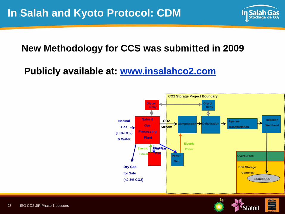
In Salah and Kyoto Protocol: CDM
Natural
Gas
(10% CO2)
& Water
Power-
GenPower-
Gen
Compression DehydrationPipeline
Transportation
Injection
Well-head
Dry Gas
for Sale
(<0.3% CO2)
Natural
Gas
Processing
Plant
CO2
Stream
Fuel Gas
Electric
PowerElectric
PowerOverburden
Stored CO2
CO2 Storage
Complex
CO2 Storage Project Boundary
Glycol
Dehy
Glycol
Dehy
New Methodology for CCS was submitted in 2009
Publicly available at: www.insalahco2.com

Primary colours
RGB
250, 166, 26
13, 145, 193
128, 195, 66
Secondary
Colours RGB
247, 218, 0
184, 47, 38
114, 15, 16
60, 26, 22
174, 197, 231
ISG CO2 JIP Phase 1 Lessons 28
Agenda
Context & Overview
In Salah JIP Phase 1: Key Learnings –CO2 Storage: Planning and Operation
–Monitoring
– Data Acquisition
– Integration
– Quantified Risk Assessment
– Informing Regulation
JIP2 Plan
Summary & Discussion

Primary colours
RGB
250, 166, 26
13, 145, 193
128, 195, 66
Secondary
Colours RGB
247, 218, 0
184, 47, 38
114, 15, 16
60, 26, 22
174, 197, 231
ISG CO2 JIP Phase 1 Lessons 29
Top Ten Lessons Learned
1. Monitoring should be part of the Field Development Plan (FDP) and routine field operations.
2. QRAs should be carried out prior to injection and periodically throughout the operation Several methodologies are available, but there is no regulatory agreement on acceptable levels of risk
3. The main leakage risks are driven by: – Legacy well-bore integrity
– Cap-rock integrity
– CO2 plume migration direction
4. Monitoring should be in service of risk assessment: designed to address site-specific risks
5. Acquisition, modelling and integration of a full suite of initial baseline data (specifically caprock cores and geo-mechanical logs) is essential for evaluating long-term integrity.
6. Compared to hydrocarbon developments, CO2 storage projects require the integration of a wider-scope of datasets (InSAR, soil gas, seismic) over a greater aerial/vertical extent (overburden and area of possible migration).
7. A diverse suite of different technologies should be deployed and integrated.
8. Injection strategies, rates and pressures need to be linked to geomechanical modelling of the reservoir and the overburden and continuously monitored and managed.
9. CO2 plume development is not homogeneous and requires high-resolution data for reservoir characterization and modelling.
Effects that require advanced, coupled modelling are: fluid-dynamics, rock mechanics and temperature
10. The regulation of CO2 storage projects is immature, but In Salah could retrospectively comply with the EU CCS Directive and the requirements of the Clean Development Mechanism.
In Salah can inform emerging CCS regulatory frameworks around the world.

Primary colours
RGB
250, 166, 26
13, 145, 193
128, 195, 66
Secondary
Colours RGB
247, 218, 0
184, 47, 38
114, 15, 16
60, 26, 22
174, 197, 231
ISG CO2 JIP Phase 1 Lessons 30
Questions?
www.insalahco2.com