IN-ROW RETRACTABLE BLADES - Gearmore Blade Book.pdf · IN-ROW RETRACTABLE BLADES Operation, Service...
22
IN-ROW RETRACTABLE BLADES Operation, Service & Parts Manual May 2001 FORM: In-RowBladeBook.QXD
Transcript of IN-ROW RETRACTABLE BLADES - Gearmore Blade Book.pdf · IN-ROW RETRACTABLE BLADES Operation, Service...

IN-ROWRETRACTABLE
BLADESOperation, Service
& Parts Manual
May 2001
FORM: In-RowBladeBook.QXD

General Safety Instructions . . . . . . . . . . . . . . . .1
Sensing Device Adjustment . . . . . . . . . . . . . . . . .2
Sensing Rod Adjustment . . . . . . . . . . . . . . . . . . .3
General Information . . . . . . . . . . . . . . . . . . . . . .4
General Operating Tips . . . . . . . . . . . . . . . . . . . .5
General Maintenance . . . . . . . . . . . . . . . . . . . . .6
Spare Parts . . . . . . . . . . . . . . . . . . . . . . . . . . .7-19
Limited Warranty . . . . . . . . . . . . . . . . . . . . . . .20
Date of Purchase:_____________________________
Model Number:_______________________________
Serial Number: _______________________________
TABLE OF CONTENTS

If you leave the tractor, even temporarily, verify that the implement has been lowered to the ground or positioned in such a way as not to be dangerous for the operator and other people.
If you leave the tractor switch the engine off.
In case of doubt on what to do during the installation, working and maintenance, switch the engine of the tractor off, consult the manual or your dealer.
Start up the implement only when you are properly seated.
In case of emergency, immediately switch the engine of the tractor off.
It is forbidden to execute operations different from those stated in the usage and purpose of the implement.
It is forbidden to add accessories, options and whatever else which has not been previously authorized by the manufacturer.
The machine must not be used by more than one operator at a time.
GENERAL SAFETY INSTRUCTIONS
Page 1

TURN OFF THE ENGINE BEFORE PERFORMINGTHE FOLLOWING OPERATION
Your in-row blade comes with 3 springs:
1. Light duty spring for working in young plants or plants with delicate bark.
2. Medium duty spring, which is the spring used in most applications.
3. Heavy duty spring for when there are tall or sturdy weeds.
To change the return spring (pict. 9 pos. 7) remove the lock pin (pos. 8) take off the flat washer, take off the spring and change it with a spring more adequate to the kind of work you are going to perform.
Special Note: For the most sensitive sensor setting (lightest pressure on the plants), remove the spring (pict. 09, pos. 7). Be sure to reinstall the flat washer and click-pin (pict. 09, pos. 8).
Never remove the spring shown in (pict. 9, pos. 9) unless damaged and then only replace with the same size.
SENSING DEVICE ADJUSTMENT
Page 2

Turn off engine before performing the following operations
To insure that the in-row retractable blade is operating correctly, a few simple adjustments are necessary.
Make sure the rod is extended to the same length as the blade (pict. 13).By moving the rod out longer than the blade, the blade will leave a larger circle around the vine.
Make sure the sensing rod is parallel to the blade (pict. 13, pos. 2), which is the correct position for most operations.
In (pict. 13, pos. 1), the rod is slightly forward. We suggest this position to work in plants with deformed trunks, such as old vineyards.
Note: Ground speed will affect the sensor rod setting requirements. A faster ground speed also requires that the rod is further in front of the blade.
In (pict. 13, pos. 3), the rod is shown in the incorrect position.
To adjust the sensor rod, turn the 2 fastening bolts (pict. 13, pos. 4).
SENSING ROD ADJUSTMENT
Page 3

GENERAL INFORMATION
Page 4
1. Two blade lengths are available, 24 and 31 inch. Make sure you have thebest length for your operation.
2. To operate correctly, the single blade requires 6 G.P.M. The double bladerequires a flow divider and 12 G.P.M.
3. If the hydraulic output of the tractor is too high, a flow restrictor is required.
4. The hydraulic pressure requirement is a minimum of 2000 P.S.I.

1. The blade should be set 1-1/2 to 3 inches under the soil.
2. The sensor rod should be as long as the blade used.
3. If the in-row blades are mounted on a disc, cultivator, etc., set the blade to operate at only 1-1/2 to 3 inches deep.
4. If you are mounting tools next to the blade, set depth of tools approximately 1 inch deeper.
5. The blade should be operated 4 to 6 inches beyond the center line of the vine row.
6. The blade must have a valve to override the system to retract the blade from the tractor seat.
7. To begin, operate in-row retractable blade at approximately 2 miles per hour. When comfortable with the operation, you can go to speeds of up to 4 M.P.H.
8. Ground speed will affect the sensor rod setting requirements. A faster ground speed requires that the rod setting be further in front of the blade.
GENERAL OPERATING TIPS
Page 5
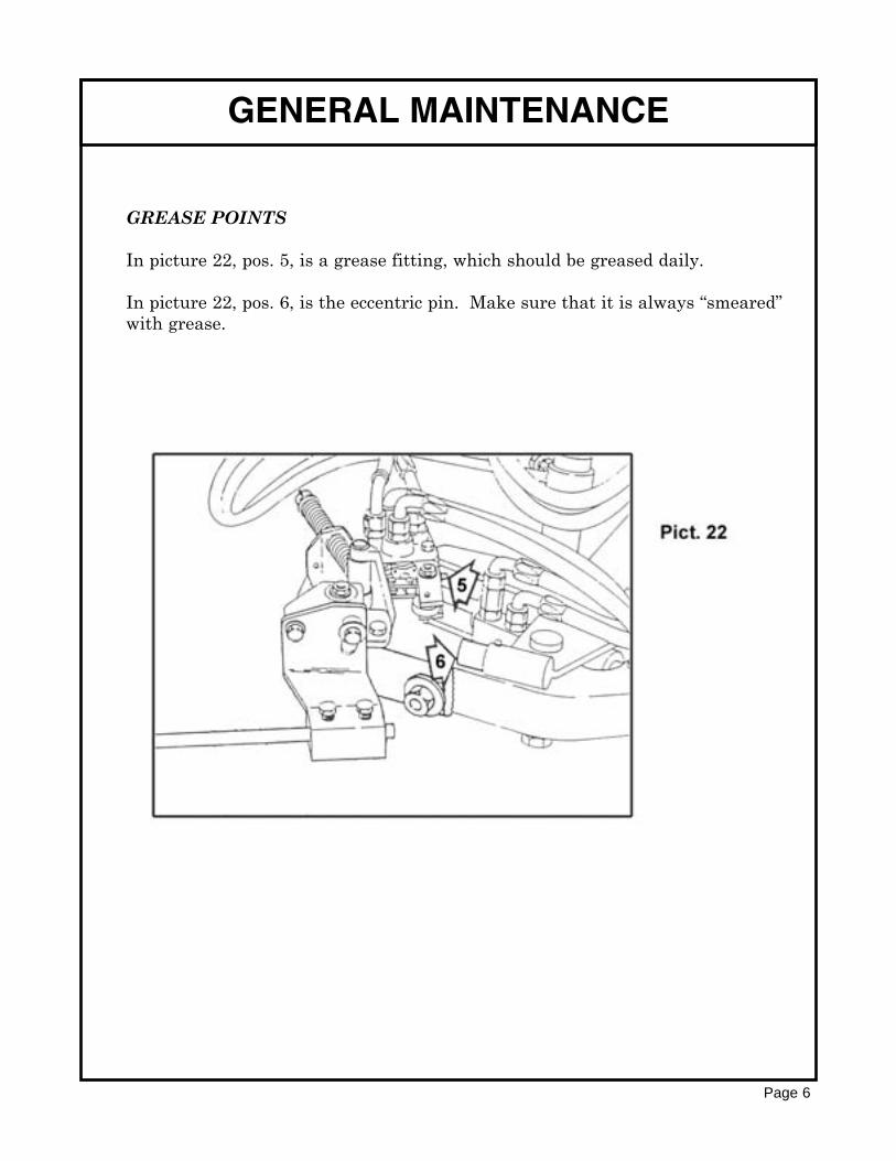
GREASE POINTS
In picture 22, pos. 5, is a grease fitting, which should be greased daily.
In picture 22, pos. 6, is the eccentric pin. Make sure that it is always “smeared”with grease.
Page 6
GENERAL MAINTENANCE

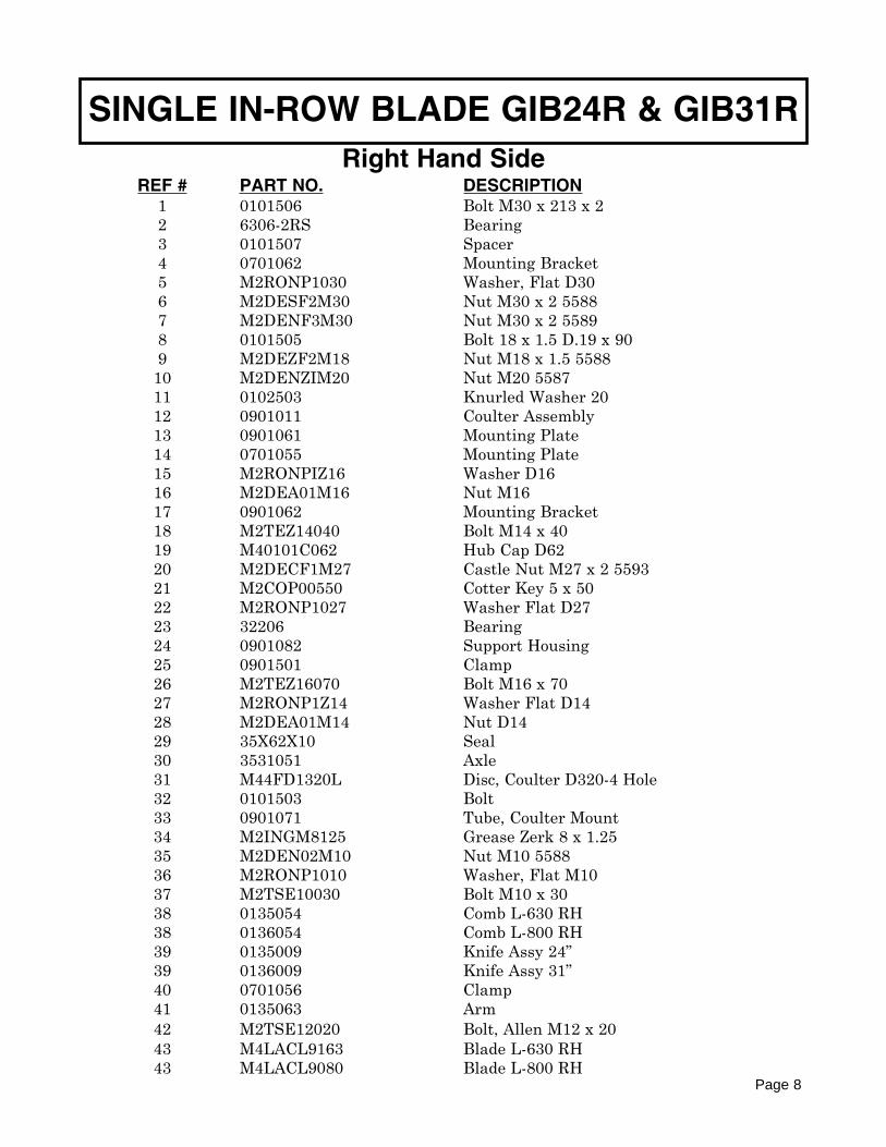
SINGLE IN-ROW BLADE GIB24R & GIB31R
Page 7
Right Hand Side
SINGLE IN-ROW BLADE GIB24R & GIB31R
REF # PART NO. DESCRIPTION1 0101506 Bolt M30 x 213 x 22 6306-2RS Bearing3 0101507 Spacer4 0701062 Mounting Bracket5 M2RONP1030 Washer, Flat D306 M2DESF2M30 Nut M30 x 2 55887 M2DENF3M30 Nut M30 x 2 55898 0101505 Bolt 18 x 1.5 D.19 x 909 M2DEZF2M18 Nut M18 x 1.5 5588
10 M2DENZIM20 Nut M20 558711 0102503 Knurled Washer 2012 0901011 Coulter Assembly13 0901061 Mounting Plate14 0701055 Mounting Plate15 M2RONPIZ16 Washer D1616 M2DEA01M16 Nut M1617 0901062 Mounting Bracket18 M2TEZ14040 Bolt M14 x 4019 M40101C062 Hub Cap D6220 M2DECF1M27 Castle Nut M27 x 2 559321 M2COP00550 Cotter Key 5 x 5022 M2RONP1027 Washer Flat D2723 32206 Bearing24 0901082 Support Housing25 0901501 Clamp26 M2TEZ16070 Bolt M16 x 7027 M2RONP1Z14 Washer Flat D1428 M2DEA01M14 Nut D1429 35X62X10 Seal30 3531051 Axle31 M44FD1320L Disc, Coulter D320-4 Hole32 0101503 Bolt33 0901071 Tube, Coulter Mount34 M2INGM8125 Grease Zerk 8 x 1.2535 M2DEN02M10 Nut M10 558836 M2RONP1010 Washer, Flat M1037 M2TSE10030 Bolt M10 x 3038 0135054 Comb L-630 RH38 0136054 Comb L-800 RH39 0135009 Knife Assy 24”39 0136009 Knife Assy 31”40 0701056 Clamp41 0135063 Arm42 M2TSE12020 Bolt, Allen M12 x 2043 M4LACL9163 Blade L-630 RH43 M4LACL9080 Blade L-800 RH
Page 8
Right Hand Side

SINGLE IN-ROW BLADE GIB24R & GIB31R
Page 9
Right Hand Side

SINGLE IN-ROW BLADE GIB24R & GIB31R
REF # PART NO. DESCRIPTION
103 M50103505 Nipple 1/2”104 M5RB00012 Washer 1/2” Bonded105 M51R21M12 Quick Coupler 1/2” Male106 M5TC1012F Cover Quick Coupler107 M50103254 Piston Rod
*108 M50103213 Seal109 M50103212 Gland Packing
*110 M50103211 Seal111 0903502 Hose
*112 M50103218 O-Ring113 M50103255 Barrel, Hydraulic Cylinder114 M50103256 Ball Kit, Hydraulic Cylinder
*115 M50103216 Seal116 M50103217 Piston117 M5RC38MMM Adapter “T” 3/8” Male118 M5RC38GMF Nipple M-F 3/8”119 M5RB00038 Washer Bonded 3/8”120 M50103506 Nipple 3/8”121 0103559 Cylinder Blade Actuator122 0903507 Hose123 0903503 Hose124 M5VL0000M Flow Divider125 M50203502 Adaptor “T” 1/2”126 0104509 Hose127 0903501 Hose128 M2COP00325 Cotter Pin 3 x 25129 0103504 Pin130 M2TCE05016 Allen Screw 5 x 16131 M50103011 Cap Valve132 M50103012 Spacer133 M50103013 Washer D5134 M50103014 Bolt M5 x 18135 0903504 Hose136 M50103016 Spring137 M50103017 Disc f/Spring138 M2COPSC004 Lynch Pin139 M2RONP1Z15 Washer D14 x 42140 M50103015 Disc f/Spring141 0103521 Spring142 0103514 Eccentric Lockpin 30mm143 M2RONP1010 Washer D10144 M2DEAF1M12 Nut m12 x 1.25145 M2RONP1Z12 Washer D12146 0103001 Complete Jack
Page 10
Right Hand Side

SINGLE IN-ROW BLADE GIB24R & GIB31R
REF # PART NO. DESCRIPTION
147 0103525 Spring148 0103511 Bolt149 M2RONP1Z14 Washer D14150 M2DEA01M14 Nut M14151 M5VMD2100 Complete Valve152 M50103508 Relief Valve 1/2” - 3/8”153 0103515 Roller154 M2SSP10045 Roll Pin 10 x 45155 0103526 Spring 3.5156 0103523 Spring 2.5157 0103524 Spring 3158 M2MDE18091 Washer 18 x 9.2 x 1159 M2DEA01M08 Nut M8160 M50103019 O-Ring161 0103051 Rod162 0103522 Spring 2163 M21NGM8125 Grease Zerk 8 x 1.25164 0103506 Jack165 M50103018 Distributor Support166 0103519 Pin167 0103516 Bracket Register168 M50103001 Valve Assembly169 M2DEN02M08 Nut M8 5588170 M2RONP1Z08 Washer D8171 M2COP00220 Cotter Pin 2 x 20172 M2RONP1006 Washer D6173 M2TEZ08070 Bolt M8 x 70174 0103518 Pin 6 x 28175 0103512 Fork Distributor176 0103520 Spring 3 - L=29177 M50103023 Link178 0103517 Pin179 0903505 Hose180 M5BUCA012 Banjo Bolt 1/2”181 0503585 Valve Bracket182 M2TEZ08035 Bolt M8 x 35183 0503085 Valve Holder184 0103513 Fork185 6202-2RS Bearing186 0103510 Support187 0103507 Spacer188 M2TEZ12040 Bolt M12 x 40189 0101514 Washer 12.5 x 6190 0103508 Bolt
Page 11
Right Hand Side

SINGLE IN-ROW BLADE GIB24R & GIB31R
REF # PART NO. DESCRIPTION
x191 0701066 Wand Extension192 M2COPMO008 Lockpin D8193 0903506 Hose194 M2TE008065 Bolt 8 x 65195 M50403019 O-Ring 2.115196 M50503018 Seal197 M2TEZ12030 Bolt M12 x 30198 M5R100006 Reducer M-1/2 - F-3/8199 0103509 Rod Clevis D-35 RH200 M5DE00030 Control Valve Single Spool201 M5ED00111 Cap Valve202 M50503017 Bolt M5 x 40203 M2TEZ12025 Bolt M12 x 25
x204 0701065 Wand Extension205 M50503016 spacer206 M50503015 Bolt M8 x 20207 M5BUCA038 Banjo Bolt 3/8”208 M50503014 Disc Spring209 M50503013 Spring210 0145563 Sensing Rod L=680
0145562 Sensing Rod L=850211 M50503012 Valve Handle212 M5DSV0040 Handle Kit213 M50503011 Pressure Regulator
* RTONEW0000 Hydraulic Cylinder Seal Kitx 0503010 Wand Height Extension Assembly
Page 12
Right Hand Side
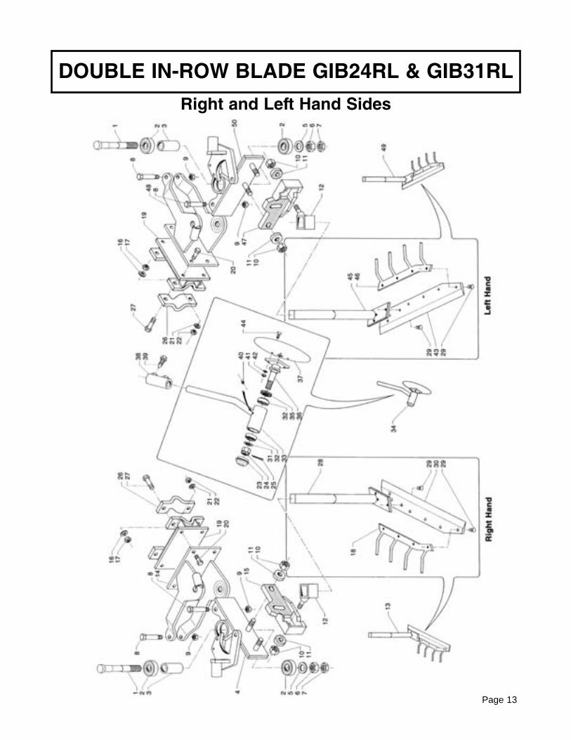
DOUBLE IN-ROW BLADE GIB24RL & GIB31RL
Page 13
Right and Left Hand Sides

REF # PART NO. DESCRIPTION
1 0101506 Bolt M30 x 213 x 22 6306-2RS Bearing 30 x 72 x 193 0101507 Spacer4 0701062 Mounting Bracket RH5 M2RONP1030 Washer, Flat D306 M2DESF2M30 Nut M30 x 2 55887 M2DENF3M30 Nut M30 x 2 55898 0101505 Bolt 18 x 1.5 - M19 x 909 M2DEZF2M18 Nut M18 x 1.5 5588
10 M2DENZ1M20 Nut M20 558711 0102503 Knurled Washer 2012 0701056 Clamp13 0135009 Knife Assy. 24” RH13 0136009 Knife Assy. 31” RH14 0901061 Mounting Bracket RH15 0701055 Mounting Plate RH16 M2RONPIZ16 Washer D1617 M2DEA01M16 Nut M1618 0135054 Comb L-630 RH18 0136054 Comb L-800 RH19 0901062 Mounting Bracket20 M2TEZ14040 Bolt M14 x 4021 M2RONP1Z14 Washer Flat D1422 M2DEA01M14 Nut D1423 M40101C062 Hub Cap D6224 M2DECF1M27 Castle Nut M27 x 2 559325 M2COP00550 Cotter Key 5 x 5026 0901501 Clamp27 M2TEZ16070 Bolt M16 x 7028 0135063 Arm29 M2TSE12020 Bolt, Allen M12 x 2030 M4LACL9163 Blade L-630 RH30 M4LACL9080 Blade L-800 RH31 M2RONP1027 Washer Flat D2732 32206 Bearing33 0901082 Support Housing34 0901011 Coulter Assy.35 35X62X10 Seal36 3531051 Axle37 M44FD1320L Disc, Coulter D320-4 Hole38 0901071 Tube, Coulter Mount39 0101503 Bolt 16 x 4040 M2INGM8125 Grease Zerk 8 x 1.2541 M2DEN02M10 Nut M10 558842 M2RONP1010 Washer, Flat M10
DOUBLE IN-ROW BLADE GIB24RL & GIB31RL
Page 14
Right and Left Hand Sides

DOUBLE IN-ROW BLADE GIB24RL & GIB31RL
Page 15
REF # PART NO. DESCRIPTION
43 M4LACL6305 Blade L=630 LH43 M4LACL8005 Blade L=800 LH44 M2TSE10030 Bolt, Allen 10 x 3045 0335063 Arm LH46 0335054 Comb L=630 LH46 0336054 Comb L=800 LH47 0335055 Mounting Plate LH48 0990061 Mounting Bracket LH49 0335009 Knife Assy. 24” LH49 0336009 Knife Assy. 31” LH50 0990062 Mounting Bracket LH
Right and Left Hand Sides

DOUBLE IN-ROW BLADE GIB24RL & GIB31RL
Page 16
Right and Left Hand Sides

DOUBLE IN-ROW BLADE GIB24RL & GIB31RL
REF # PART NO. DESCRIPTION
101 M50103505 Nipple 1/2 m-m102 M5RB00012 Washer Bonded 1/2103 M51R21M12 Quick Coupler Male104 M5TC1012F Cover Q/C105 0903505 Hose 1/2” R2 1950 mm F90-F90106 0903507 Hose107 M5BUCA038 Banjo Bolt 3/8108 M50103508 Nipple m-m 1/2 - 3/8109 M2TE010020 Bolt 10 x 20110 0901502 Bracket Control Valve111 M50403019 O-Ring112 M50503018 Guide O-ring113 M5R100006 Reducer M 1/2 - F 3/8114 M5RB00038 Washer Bonded 3/8115 M5BUCA012 Banjo Bolt 1/2116 M2TEZ08035 Bolt 8 x 35117 M50503012 Handle118 M5DE00030 Control Valve119 M5ED00111 Body Control Valve120 M50503017 Bolt 5 x 40121 M2DEA01M08 Locknut M8122 0903503 Hose 1350 FNPT - FNPT123 M5DFVL012 Manifold Divider124 M5BUCA212 Banjo Bulkhead 1/2125 M5ROF1M41 Banjo Nipple 1/2 x 1/2126 M5RFFF012 Tee Fitting 1/2 Female127 M50503016 Spacer128 M50503015 Bolt 8 x 20129 M50503014 Seat Spring130 M50503013 Spring131 0901503 Bracket Valve Pocket132 M2DEN02M08 Nut M8133 M2RONP1Z08 Washer D8134 0503085 Pocket Control Valve135 0901504 Stud M8136 M50503011 Relief Valve137 M2TE006065 Bolt 6 x 65138 M5DCV0040 Valve Lever Assy.139 0901505 Mounting Plate Flow Divider140 M2DEN02M06 Nut M6141 M50603501 Nipple bulkhead 1/2” m-m142 0145563 Sensing Rod 24” RH142 0145562 Sensing Rod 31” RH143 M2TEZ12025 Bolt 12 x 25144 M2RONP1Z12 Washer Flat D12
Page 17
Right and Left Hand Sides

DOUBLE IN-ROW BLADE GIB24RL & GIB31RL
REF # PART NO. DESCRIPTION
145 M50203501 Nut Bulkhead Fitting 1/2”146 M2TE008050 Bolt 8 x 50147 0701065 Bracket Wand Attachment LH148 0303509 Rod Clevis L.H.149 M2TEZ12030 Bolt 12 x 30150 0101514 Washer Flat 12.5 x 36 x 6151 M2RONP1006 Washer Flat D6152 M2COP00220 Cotter Key 2 x 20 - 4.8153 M50103213 O-Ring154 M50103212 Piston155 M50103211 O-ring156 0103513 Fork157 M2DEA01M14 Locknut M14158 M2RONP1Z14 Washer Flat D14159 6202-2RS Bearing 6202-2RS160 0303510 Support Bearing161 0103507 Spacer162 M2TEZ12040 Bolt 12 x 40163 0103508 Lockpin164 0335066 Bracket Extension165 M2COPMO008 Lynch Pin D8166 0903502 Hose 3800 - 3/8 R2 F90 - F90167 M50103214 Rod Cylinder168 M50103218 O-ring169 M50103215 Barrel Cylinder171 M50103216 O-ring172 M50103217 Piston173 0103517 Pin D10 x 100174 M5RC38MMM Tee 3/8” m-m-m175 M5RC38GMF Nipple 3/8M - 3/8F176 0103518 Pin D6 x 28177 0103512 Fork178 0103520 Spring D3 x 29179 M50103023 Link180 0103519 Pin D6 x 38181 M2COP00325 Cotter Key 3 x 25182 M2RONP1010 Washer Flat D10183 0303516 Register Bracket LH184 M50103506 Nipple 3/8 m-m185 M2TCE05016 Bolt 5 x 16186 M50103018 Support Valve Fork187 M50103019 O-ring OR616188 0103505 Cylinder GIB24 RH189 0103051 Actuator Rod190 0103522 Spring 2
Page 18
Right and Left Hand Sides

DOUBLE IN-ROW BLADE GIB24RL & GIB31RL
REF # PART NO. DESCRIPTION
191 0103526 Spring 3.5192 0103523 Spring 2.5193 0103524 Spring 3194 M5VL0000M Manifold Tee195 M5VMD2100 Relief Valve196 M50103011 Cover Valve Spool197 0103504 Pin D10 x 53198 M2RONP1Z15 Washer Flat D14 x 42199 M50103012 Spacer200 M50103013 Washer Flat D5201 M50103014 Bolt 5 x 18202 M50103015 Seat Spring203 M50103016 Spring Valve204 M50103017 Seat Spring205 M2COPSC004 Lynch Pin D4.5206 0104509 Hose 3/8 F90 - F90 - 600mm207 0903504 Hose 1/2 F90 - FD - 1600mm208 0903501 Hose 3/8 F90 - Banjo - 3800mm209 0103521 Spring210 0103514 Eccentric Lockpin D30211 M2DEAF1M12 Locknut M12 x 1.25212 0103001 Complete Jack RH213 0103525 Return Spring Freewheel RH214 0103511 Pin215 0304569 Hose 3/8 F90 - F90216 M2MDE18091 Washer Flat 9.2 x 18 x 1217 0103515 Roller218 M2SSP10045 Roll Pin 10 x 45219 M2TEZ08070 Bolt 8 x 70220 M50103001 Valve Distributor RH221 M2INGM8125 Grease Zerk M8 x 1.25222 0103506 Fork223 M50303001 Distributor Valve LH224 0103516 Register Bracket RH225 0903506 Hose 1/2” F90 - Banjo - 3600mm226 0103510 Support Bearing227 0701066 Bracket Extension RH228 0103509 Bracket Wand Attachment RH229 M50303215 Cylinder Barrel LH230 0303508 Cylinder LH231 0303001 Complete Jack LH232 0303525 Return Spring Freewheel LH233 0345563 Sensing Wand 24” LH233 0345562 Sensing Wand 31” LH
Page 19
Right and Left Hand Sides

Page 20
GEARMORE, INC., warrants each new Gearmore product to be free from defects in materi-al and workmanship for a period of twelve (12) months from date of purchase to the originalpurchaser. This warranty shall not apply to implements or parts that have been subject tomisuse, negligence, accident, or that have been altered in any way.
Our obligation shall be limited to repairing or replacement of any part, provided that suchpart is returned within thirty (30) days from date of failure to Gearmore through the dealerfrom whom the purchase was made, transportation charges prepaid.
This warranty shall not be interpreted to render us liable for injury or damages of any kind ornature, direct, consequential or contingent, to person or property. This warranty does notextend to loss of crops, loss because of delay in harvesting or any other expenses, for anyother reasons.
Gearmore in no way warranties engines, tires, or other trade accessories, since these itemsare warranted separately by these respective manufacturers.
Gearmore reserves the right to make improvements in design or changes in specification atany time, without incurring any obligations to owners or units previously sold.
GEARMORE, INC.13477 Benson Ave.
Chino, CA 91710Always refer to and heed machine operating warning decals on machine.
LIMITED WARRANTY
The serial number of this product is stored in our computer database, thussubmitting a warranty registration card is not required.