in response to the Department of Energy’s (DOE) notice of ...
37
September 29, 2015 Ms. Brenda Edwards U.S. Department of Energy Building Technologies Program, Mailstop EE-5B 1000 Independence Avenue SW Washington, DC 20585-0121 Re: Energy Conservation Standards for Residential Boilers; Proposed Rule Docket Number EERE-2012-BT-STD-0047 Dear Ms. Edwards: On July 1, 2015 the Air-Conditioning, Heating, and Refrigeration Institute (AHRI) submitted comments in response to the Department of Energy’s (DOE) notice of proposed rulemaking (NOPR) regarding amended efficiency standards for residential boilers issued in the March 31, 2015 Federal Register. In those comments we noted that the NOPR analysis has not accurately assessed the number of replacement installations that will require some work of the venting system and the cost of that vent work at the minimum AFUE levels proposed by DOE. We informed DOE that AHRI had contracted the Gas Technology Institute (GTI) to study the performance of vent systems when connected to boilers operating at the efficiencies considered in the DOE analysis. This research project has been completed and the GTI report “The Impact of Increasing Residential Boiler Efficiency Levels on Vent Performance” is attached. AHRI’s previous comments detailed our concerns with the widely varying characteristics of venting systems to which existing boilers are connected and the manufacturer’s awareness of the need to have boiler designs that are robust enough to operate safely and properly when connected to these venting systems when the existing boiler is replaced. We presented our position that boilers with AFUE ratings in the 83.5% to 87% range result in near condensing installations. This GTI study, which analyzed the AFUE levels of 83%, 84% and 85% validates that position and shows how the potential for unacceptable wet times occurring in various parts of the vent system increases, particularly at the 84% and 85% AFUE levels. As explained in the report, the “wet time” limits are values that have been used to establish the coverage for properly sized and configured vent systems for atmospheric gas-fired boilers in the National Fuel Gas Code. When the Vent-II analysis shows wet times exceeding these limits, it is an indication of excessive condensation which increases the potential for condensate-induced corrosion and subsequent vent system failure. From the perspective of this rulemaking at least two aspects of the analysis must be redone. DOE must analyze the changes in product designs and installation instructions that manufacturers will make at the higher proposed AFUE levels to address this increased potential for excessive condensation to occur in existing vent systems. The design change is not just the simple addition of more heat exchanger area. We have already noted that the proposed level for gas boilers in the NOPR will likely cause a majority of models to use a fan-assisted design. It may also cause manufacturers to specify that parts or all of the venting system should have water-tight joints and use materials that are corrosion resistant. Also DOE must analyze the added cost to rework or replace existing venting systems in replacement installations. The results of the analysis done by GTI show that at an 84% or 85% level the potential for excessive
Transcript of in response to the Department of Energy’s (DOE) notice of ...
September 29, 2015
Ms. Brenda Edwards
U.S. Department of Energy
Building Technologies Program, Mailstop EE-5B
1000 Independence Avenue SW
Washington, DC 20585-0121
Re: Energy Conservation Standards for Residential Boilers; Proposed Rule
Docket Number EERE-2012-BT-STD-0047
Dear Ms. Edwards:
On July 1, 2015 the Air-Conditioning, Heating, and Refrigeration Institute (AHRI) submitted comments
in response to the Department of Energy’s (DOE) notice of proposed rulemaking (NOPR) regarding
amended efficiency standards for residential boilers issued in the March 31, 2015 Federal Register. In
those comments we noted that the NOPR analysis has not accurately assessed the number of replacement
installations that will require some work of the venting system and the cost of that vent work at the
minimum AFUE levels proposed by DOE. We informed DOE that AHRI had contracted the Gas
Technology Institute (GTI) to study the performance of vent systems when connected to boilers operating
at the efficiencies considered in the DOE analysis. This research project has been completed and the GTI
report “The Impact of Increasing Residential Boiler Efficiency Levels on Vent Performance” is attached.
AHRI’s previous comments detailed our concerns with the widely varying characteristics of venting
systems to which existing boilers are connected and the manufacturer’s awareness of the need to have
boiler designs that are robust enough to operate safely and properly when connected to these venting
systems when the existing boiler is replaced. We presented our position that boilers with AFUE ratings in
the 83.5% to 87% range result in near condensing installations. This GTI study, which analyzed the
AFUE levels of 83%, 84% and 85% validates that position and shows how the potential for unacceptable
wet times occurring in various parts of the vent system increases, particularly at the 84% and 85% AFUE
levels. As explained in the report, the “wet time” limits are values that have been used to establish the
coverage for properly sized and configured vent systems for atmospheric gas-fired boilers in the National
Fuel Gas Code. When the Vent-II analysis shows wet times exceeding these limits, it is an indication of
excessive condensation which increases the potential for condensate-induced corrosion and subsequent
vent system failure.
From the perspective of this rulemaking at least two aspects of the analysis must be redone. DOE must
analyze the changes in product designs and installation instructions that manufacturers will make at the
higher proposed AFUE levels to address this increased potential for excessive condensation to occur in
existing vent systems. The design change is not just the simple addition of more heat exchanger area.
We have already noted that the proposed level for gas boilers in the NOPR will likely cause a majority of
models to use a fan-assisted design. It may also cause manufacturers to specify that parts or all of the
venting system should have water-tight joints and use materials that are corrosion resistant. Also DOE
must analyze the added cost to rework or replace existing venting systems in replacement installations.
The results of the analysis done by GTI show that at an 84% or 85% level the potential for excessive

DOE NOPR
Residential Boiler Std.
September 29, 2015
Page 2 of 2
wetting in the vent system increases. To address this increased potential for excessive condensate in the
vent system, the specifications for the size, configuration, and materials for venting systems appropriate
for models at those efficiency levels may be very different than the requirements which governed the
existing vent system in a home. In such cases there will be added cost to rework or replace the vent
system. This circumstance will apply to a much larger percentage of installations than assumed in the
current DOE analysis.
We request DOE to review this report and reassess the cost of boilers at the minimum AFUE levels
proposed in the March 31, 2015 NOPR. We believe that a proper assessment will show that for many
consumers the total installed cost of a higher efficiency boiler will outweigh the value of the energy
savings provided by that boiler.
There is one other technical issue which we had been inadvertently omitted in our earlier comments. The
NOPR proposes that oil-fired steam boilers meet the same minimum AFUE standard as oil-fired hot water
boilers. This is not a technically reasonable proposal. To this point different AFUE levels have been
specified for steam and hot water boilers. That is still the case for the amended standards being proposed
for gas fired boilers. The residential boiler market is not large. The economies of scale that exist in the
residential furnace market are not available to the manufacturers of residential boilers. It is very common
to design a residential oil fired boiler model that can operate as either a steam boiler or a hot water boiler
depending on the boiler trim applied to the basic design. For an oil fired boiler that is marketed as either a
steam boiler or a hot water boiler, the AFUE for the steam boiler version will always be lower than the
hot water version of that same design model. It is not economic for a boiler manufacturer to design and
have separate tooling for an oil fired steam models and an oil fired hot water models. Pattern equipment
costs alone can get close to a half of million dollars. The proposed minimum 86% AFUE for steam oil-
fired boilers is forcing an economic burden on the manufacturer greater than the NOPR estimates because
it will require either the development of separately designed steam boiler models or substantial changes to
the design of hot water models to raise the AFUE above 86% so that when the steam version of that
design is tested it can comply with the proposed 86% minimum. Neither option is justifiable; DOE
should continue to specify a different, lower AFUE level for oil fired steam boilers as compared to that
specified for oil -fired hot water boilers.
Respectfully Submitted,
Frank A. Stanonik
Chief Technical Advisor
Page | i
GTI PROJECT NUMBER 21832
The Impact of Increasing Residential Boiler Efficiency Levels on Vent Performance
Reporting Period:
June 24 – August 31, 2015
Report Issued:
August 31, 2015
Revision No.:
03
Prepared For:
Frank Stanonik
Chief Technical Advisor
AHRI
Gas Technology Institute
1700 S. Mount Prospect Rd.
Des Plaines, Illinois 60018
www.gastechnology.org
GTI Principal Investigator
Larry Brand
R&D Director
(530) 758 - 2392 x201
FINAL REPORT
GTI Contributors:
Hunter McLaughlin
Luke Bingham
Associate Engineers
(530) 758 - 2392

Page | ii
Legal Notice
This information was prepared by Gas Technology Institute (“GTI”) for the Air Conditioning,
Heating, and Refrigeration Institute (AHRI).
Neither GTI, the members of GTI, the Sponsor(s), nor any person acting on behalf of any of
them:
a. Makes any warranty or representation, express or implied with respect to the accuracy,
completeness, or usefulness of the information contained in this report. Inasmuch as this project
is experimental in nature, the technical information, results, or conclusions cannot be predicted.
Conclusions and analysis of results by GTI represent GTI's opinion based on inferences from
measurements and empirical relationships, which inferences and assumptions are not infallible,
and with respect to which competent specialists may differ.
b. Assumes any liability with respect to the use of, or for any and all damages resulting from the
use of, any information, apparatus, method, or process disclosed in this report; any other use of,
or reliance on, this report by any third party is at the third party's sole risk.
c. The results within this report relate only to the items tested.
Page | iii
Table of Contents
Legal Notice ................................................................................................................................ ii
Table of Contents ....................................................................................................................... iii
Table of Figures .......................................................................................................................... v
List of Tables ............................................................................................................................. vi
Scope of Work ........................................................................................................................... 7
Wet Time Limits ......................................................................................................................... 7
From VENT-II and Venting Tables Research ......................................................................... 7
Analysis ..................................................................................................................................... 8
Assumptions .......................................................................................................................... 8
VENT-II Modeling ................................................................................................................... 9
Results ......................................................................................................................................12
Discussion ................................................................................................................................16
Conclusions and Implications ....................................................................................................16
References ...............................................................................................................................17
List of Acronyms .......................................................................................................................18
Appendix A – List of Assumptions and Specifications ...............................................................19
Boiler Capacity ............................................................................................................................19
Damper Specifications ..................................................................................................................19
Vent Specifications .......................................................................................................................19
Configuration ..........................................................................................................................19
Ambient Temperatures .............................................................................................................20
Vent Requirements and Assumptions .........................................................................................20
NFGC Vent Connector Requirements ......................................................................................20
VENT II Type B Section Default Thickness and Materials ............................................................20
VENT II Masonry Chimney Defaults .........................................................................................20
Vent Sizing ..............................................................................................................................21
Type B Connector / Type B Common.......................................................................................21
NFGC Vent Sizing ............................................................................................................... 21
VENT II ............................................................................................................................... 21
Single-Wall Connector / Type B Common ................................................................................21
NFGC Vent Sizing ............................................................................................................... 21
VENT II ............................................................................................................................... 21
Page | iv
Type B Connector / Masonry Chimney ....................................................................................22
NFGC Vent Sizing ............................................................................................................... 22
VENT II ............................................................................................................................... 22
Single-Wall Connector / Masonry Chimney ..............................................................................22
NFGC Vent Sizing ............................................................................................................... 22
VENT II ............................................................................................................................... 22
Boiler Profiles ..........................................................................................................................24
Boiler 1 – 120 °F Minimum Flue Outlet Temperature ................................................................24
Boiler 1 – 100 °F Minimum Flue Outlet Temperature ................................................................26
Boiler 2 – 120 °F Minimum Flue Outlet Temperature ................................................................28
Boiler 2 – 100 °F Minimum Flue Outlet Temperature ................................................................30
Boiler 3 – 120 °F Minimum Flue Outlet Temperature ................................................................32
Boiler 3 – 100 °F Minimum Flue Outlet Temperature ................................................................34
Page | v
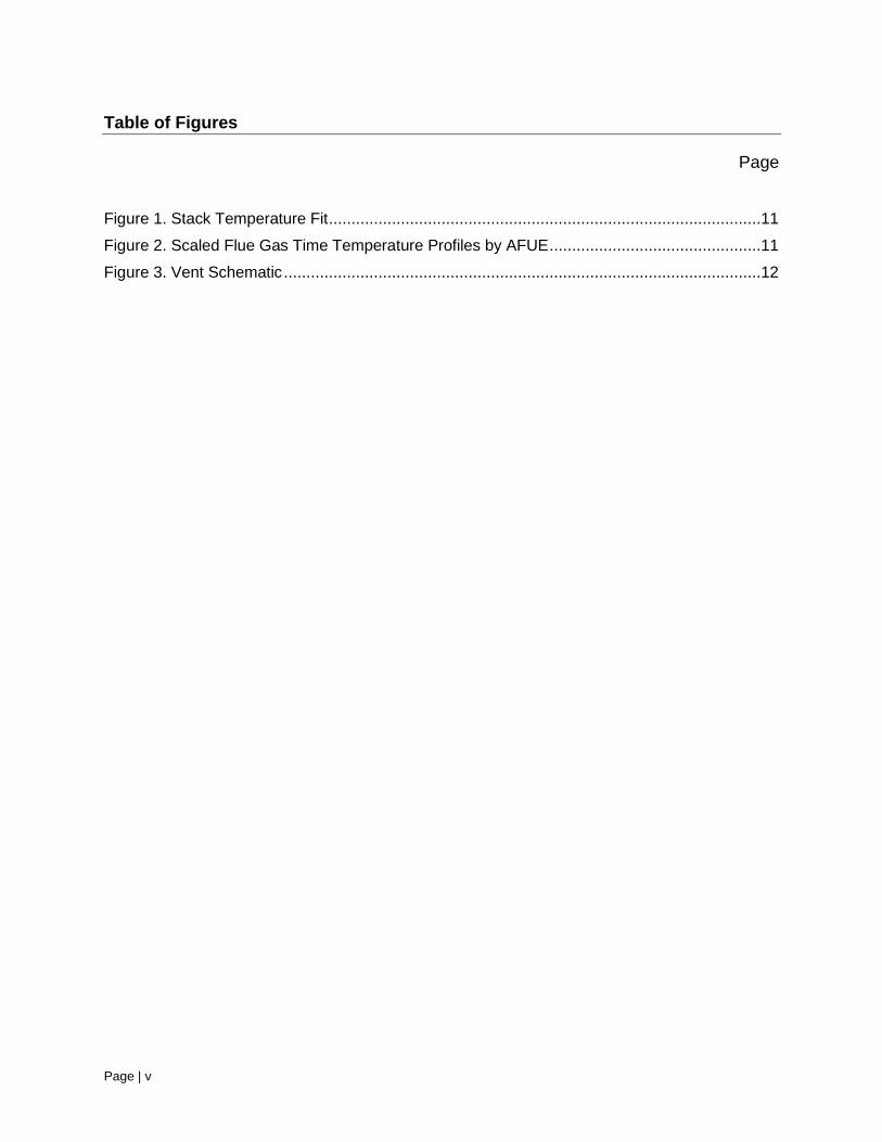
Table of Figures
Page
Figure 1. Stack Temperature Fit ................................................................................................11
Figure 2. Scaled Flue Gas Time Temperature Profiles by AFUE ...............................................11
Figure 3. Vent Schematic ..........................................................................................................12

Page | vi
List of Tables
Table 1. Boiler Characteristics 9
Table 2. Boiler Characteristics at 8% CO2 10
Table 3. Calculated Boiler Flue Gas Temperatures by Efficiency Level 10
Table 4. Boiler 1 - Type B Connector and Masonry Chimney Wet Times 13
Table 5. Boiler 2 - Type B Connector and Masonry Chimney Wet Times 13
Table 6. Boiler 3 - Type B Connector and Masonry Chimney Wet Times 13
Table 7. Sensitivity: Flue Temperature Assumption 14
Table 8. Sensitivity: Vent Connector – Type B Vent (* case not modeled) 14
Table 9. Sensitivity: Vent Connector - Masonry Chimney (* case not modeled) 15

Page | 7
Scope of Work
Introduction
The National Fuel Gas Code (ANSI Z223.1/NFPA 54 2012) (NFGC) provides vent sizing
guidelines for Category I atmospheric and fan-assisted appliances that result in a safe and
durable vent system design. The tables were developed with the primary assumption that an
appliance vent would not operate outside of its wet-time limits; that is, the vent would be wet for
a certain amount of time each cycle up to a certain limit and then operate in a dry mode for the
remainder of the cycle. As appliance efficiency increases, the flue gasses spend more time
below the dew point temperature, the length of the wet time increases and there is the potential
that the wet time limit will be exceeded and the vent will fail prematurely due to corrosion.
Objective
The objective of this project is to determine the effect of increasing boiler efficiency levels above
the current NAECA minimum on vent performance. Specifically, the project will investigate
increasing wet times in the vent and masonry chimney compared to current acceptable practice in
the NFGC.
Scope
The scope of the project is to perform VENT-II analyses on residential atmospheric boilers in
several configurations to determine the wet time in the appliance connector and vent. The wet
time in the appliance connector is compared to (1) the 3.8 minute wet time limit used in the
NFGC tables to avoid condensate-induced corrosion, and (2) the 9.8 minute boiler cycle time in
the ASHRAE 103 standard. For the masonry chimney case, the wet time limit from the NFGC
was used - wet time exceeding the boiler cycle time after 12 hours of continuous cycling. Three
boiler time/temperature curves provided by AHRI were used as the basis for the study. The
curves were adjusted for common CO2 levels and for each steady-state efficiency level to be
modeled.
A list of parameters studied is provided below:
Atmospheric boilers with vent (stack dampers) at 3 capacities and 4 steady state
efficiency/AFUE levels
Vent design – one story house with boiler in the basement
Boiler vented alone
Masonry chimney and, B Vents, with single wall and B vent connectors
Sensitivity of modeling assumptions
Wet Time Limits
From VENT-II and Venting Tables Research
The Category I venting tables in the NFGC were developed based on the ability of the appliances
to avoid condensate-induced corrosion in the vents and to be able to provide sufficient buoyancy
to vent the flue gasses. The natural draft sizing tables were originally developed in the 1950’s
and remain unchanged in the code. The fan-assisted venting system tables were developed in the

Page | 8
1980’s to address increasing efficiencies and the emerging use of fan-assisted combustion
systems.
In GRI-01/0128 A Synopsis of Gas Appliance Venting Research and Its Relevance to Higher
Efficiency Gas Furnaces and Boilers (Paul, 2002):
Single Appliance Venting Tables – Minimum vent capacities were based on the
connector (single or double wall) drying out within 3.8 minutes after the start of the 3rd
appliance cycle.
Average furnace cycling was 3.87 minutes on and 13.3 minutes off.
Three wet time limits were set for this study. In all cases, any wet time exceeding the limits is a
failure. Boiler vent connectors were evaluated at 3.8 minutes into the third appliance cycle and
9.8 minutes into the third appliance cycle to cover both the NFGC cycling rate (for furnaces) and
the ASHRAE and DOE test procedure cycling rate (for furnaces and boilers). The masonry
chimney was evaluated at 12 hours of continuous cycling. If the connectors or vents were wet
beyond those time limits, the appliance fails to dry out within the wet time limits.
Analysis
Assumptions
One story houses with boilers in the basement were modeled. The vent height was 16
feet and the lateral varied according to the rule provided in this report. For masonry
chimneys, only internal masonry chimneys were modeled.
Inside and outdoor temperature conditions matching those used to develop the venting
tables were used.
Boiler cycle times from Table 7 of ASHRAE 103 – 2007 are 9.68 minutes on and 33.26
minutes off, for a total cycle time of 42.94 minutes. Furnace cycling time is 3.87 minutes
on and 13.3 minutes off. Boiler cycling times were used for the VENT-II analysis.
The NFGC venting tables minimum capacities were developed based on dryout in the
connector after 3.8 minutes of the third appliance cycle. Dryout was evaluated in this
project based on both 3.8 minutes and 9.68 minutes into the third appliance cycle. A
violation if the wet time limits indicates that the boilers are not compliant with the tables
and thus the NFGC – extended wet times increase the likelihood of vent corrosion failure.
For masonry chimneys the criteria was based on dryout of the vent connector after 3.8
minutes into the third appliance cycle or a clay tile liner drying out after 12 hours of
continuous cycling.
For the modeling, a 1 ft. connector rise from the appliance was used and a lateral length
of no more than 18 inches per inch of vent diameter was used: 10 ft. of lateral for Type B
vents (permitted by the code) and 3 ft. of lateral for masonry chimney connectors.
Assumption that steady-state efficiency is 0.3% higher than AFUE (rule of thumb
provided by AHRI).
A more comprehensive list of assumptions is provided in Appendix A.
Page | 9
VENT-II Modeling
Three atmospheric boilers were modeled based on time temperature curves and flue gas data
provided by the manufacturer.
Table 1, below shows the combustion characteristics for the boilers from the data received.
Table 1. Boiler Characteristics
Boiler
Character
-istics
Model
Identifier
Input,
Btu/hr.
CO2,
%
Flue Gas
Temp, F
Stack
Gas
Temp,
°F
Steady
State
Efficiency
Category
Boiler 1 3SEC-
BAF-NAT
71,051 8.21% 366 292 82% I
Boiler 2 9SEC-
BAF-NAT
285,978 8.93% 384 282 82% I
Boiler 3 -
turndown
9SEC-
BAF-
NAT2
283,437 9.03% 378 299 82.3% I
Three typical boilers were developed from the manufacturer’s data for modeling purposes. The
CO2 levels were first modified to 8% CO2 make the boilers representative of the atmospheric
products in the marketplace by using the GTI combustion calculator. The resulting excess air
level was 43.4% across all the products and the flue gas maximum temperature was recalculated.
For the wet time analysis, the efficiency of the boilers was adjusted from the as-received levels
to 82% AFUE, 83% AFUE, 84% AFUE, and 85% AFUE using the GTI combustion calculator
and the following approach: first, the assumption was made that steady state efficiency is 0.3%
greater than AFUE, based on AHRI input. Then the flue temperature was calculated to match the
new CO2 percentage and steady state efficiency: 82.3%, 83.3%, 84.3%, and 85.3%. Note that
calculating the peak flue temperatures this way is based on the assumption that the increase in
efficiency will be achieved by adding heat exchanger area without impacting the combustion
characteristics of the boiler.
The resulting numbers used for VENT-II modeling are provided in Table 2 and Table 3, below.
Although the boiler CO2 and excess air levels are now the same for each efficiency level, the
capacities and time/temperature curves used in the VENT-II analysis are still unique to each
boiler.

Page | 10
Table 2. Boiler Characteristics at 8% CO2
Boilers at
8% CO2
AFUE
(0.3% below
SSE), %
Steady State Efficiency
from Combustion
Calculator, %
CO2, % Excess Air,
%
Flue Gas
Temp, F
Boiler 1 81.5% 81.8% 8.00% 43.4% 366
Boiler 2 81.0% 81.3% 8.00% 43.4% 384
Boiler 3 81.1% 81.4% 8.00% 43.4% 378
Table 3. Calculated Boiler Flue Gas Temperatures by Efficiency Level
Calculated AFUE (0.3%
below SSE), %
Steady State
Efficiency, %
CO2, % Excess Air,
%
Flue Gas
Temp, °F
82% AFUE
All Boilers 82% 82.3% 8.00% 43.4% 348
83% AFUE
All Boilers 83% 83.3% 8.00% 43.4% 312
84% AFUE
All Boilers 84% 84.3% 8.00% 43.4% 279
85% AFUE
All Boilers 85% 85.3% 8.00% 43.4% 242
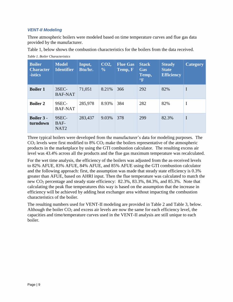
Stack gas time-temperature curves were provided from a manufacturer. The curves were
modified to fit the ASHRAE 103 AFUE cycle rate of are 9.68 minutes on and 33.26 minutes off,
for a total cycle time of 42.94 minutes. The stack data and fit are provided in Figure 1, below,
for Boiler #1.
Page | 11
Figure 1. Stack Temperature Fit
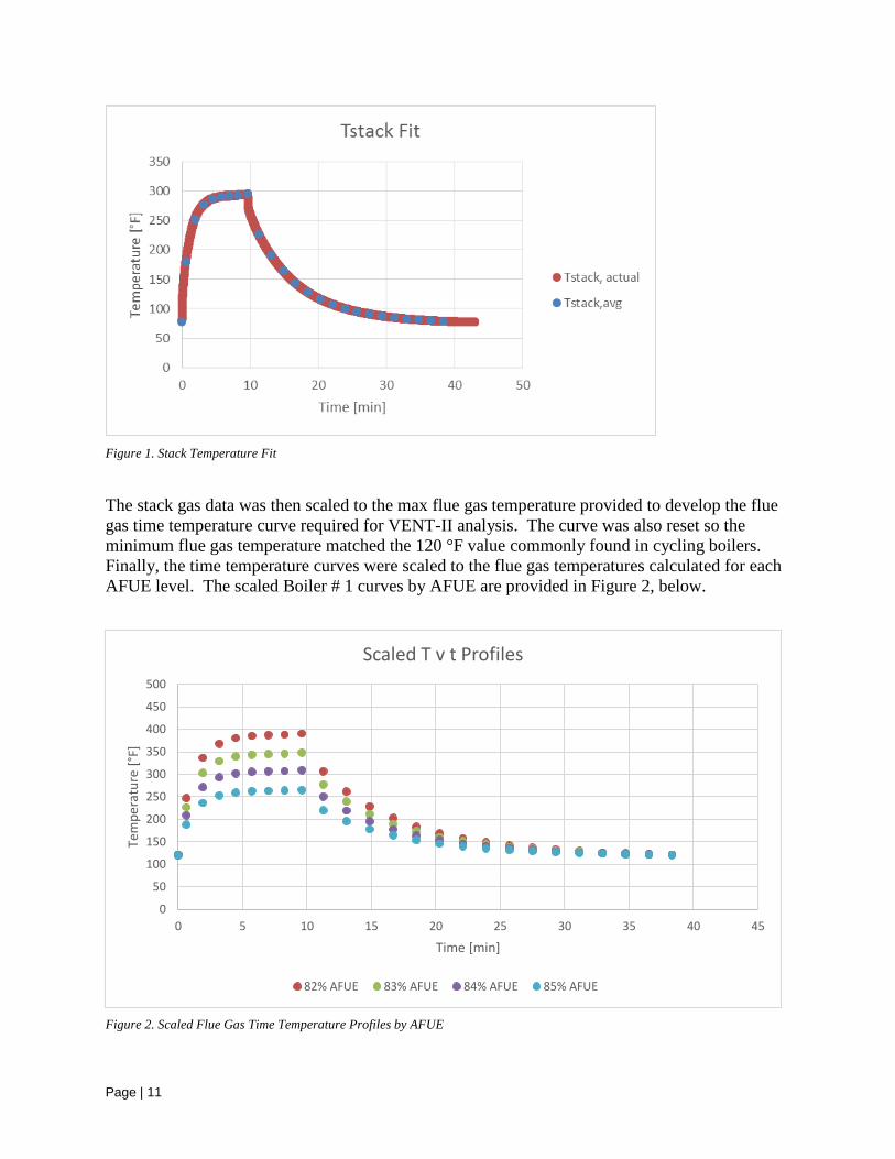
The stack gas data was then scaled to the max flue gas temperature provided to develop the flue
gas time temperature curve required for VENT-II analysis. The curve was also reset so the
minimum flue gas temperature matched the 120 °F value commonly found in cycling boilers.
Finally, the time temperature curves were scaled to the flue gas temperatures calculated for each
AFUE level. The scaled Boiler # 1 curves by AFUE are provided in Figure 2, below.
Figure 2. Scaled Flue Gas Time Temperature Profiles by AFUE
0
50
100
150
200
250
300
350
400
450
500
0 5 10 15 20 25 30 35 40 45
Tem
per
atu
re [
°F]
Time [min]
Scaled T v t Profiles
82% AFUE 83% AFUE 84% AFUE 85% AFUE
Page | 12
Type B vents with Type B vent connectors and single wall vent connectors were studied. A 10
ft. lateral length was assumed, well within the 18 inches of lateral length per inch of vent
diameter allowed by the code.
For masonry chimneys, the use of a vent damper restricts the installation of boilers (NFGC
Section 13.1.1) in some cases. Boiler 1 could not be installed in an interior masonry chimney
without relining the chimney, so that case was dropped from the chimney study. Although the
code allows the use of a 10 ft. vent connector for masonry chimneys, all of the chimneys studied
had excessive wet times with the vent damper at 10 ft. A 3 ft. connector was used to determine if
relocating the boiler closer to the chimney would be an acceptable alternative that would produce
acceptable we times.
Results
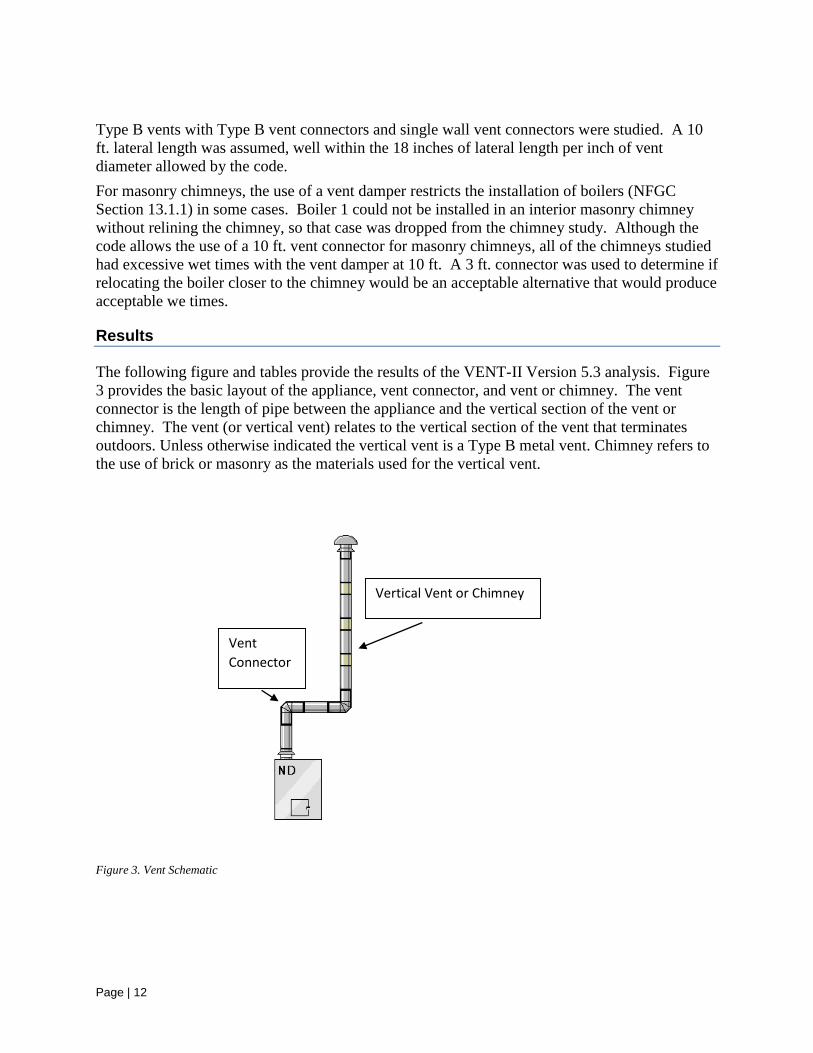
The following figure and tables provide the results of the VENT-II Version 5.3 analysis. Figure
3 provides the basic layout of the appliance, vent connector, and vent or chimney. The vent
connector is the length of pipe between the appliance and the vertical section of the vent or
chimney. The vent (or vertical vent) relates to the vertical section of the vent that terminates
outdoors. Unless otherwise indicated the vertical vent is a Type B metal vent. Chimney refers to
the use of brick or masonry as the materials used for the vertical vent.
Figure 3. Vent Schematic
Vent
Connector
Vertical Vent or Chimney

Page | 13
In the tables, shaded cells exceed the indicated wet time limits as follows:
Shading
Exceeds 3.8 minute limit
Exceeds 9.6 minute limit
Exceeds 12 hour limit for masonry chimney – wet for 41 minutes
Table 4 through Table 6 provide results for the three boilers when vented with a Type B vent
connector into a Type B vent or a masonry chimney. Efficiencies from 82% AFUE through 85%
AFUE were evaluated at a minimum flue temperature of 120 °F. Note that the wet time limit of
3.8 minutes is exceeded for all three boilers at 85% AFUE for Type B vertical vents and for all
masonry chimney configurations starting at 83% AFUE.
Table 4. Boiler 1 - Type B Connector and Masonry Chimney Wet Times
Boiler 1 - Type B Connector and Masonry Chimney Wet Times
Properties AFUE 82% 83% 84% 85%
Flue Min Temperature [°F] 120 °F 120 °F 120 °F 120 °F
Connector Wet Time, min
To a Type B Vent 2.7 3.0 3.7 5.0
To a Masonry Chimney NA* NA NA NA
Vertical Vent Wet Time, min
Masonry Chimney NA NA NA NA
*NA means not allowed by the NFGC.
Table 5. Boiler 2 - Type B Connector and Masonry Chimney Wet Times
Boiler 2 - Type B Connector and Masonry Chimney Wet Times
Properties AFUE 82% 83% 84% 85%
Flue Min Temperature [°F] 120 °F 120 °F 120 °F 120 °F
Connector Wet Time, min
To a Type B Vent 2.0 2.7 3.0 4.0
To a Masonry Chimney 2.3 2.7 3.3 4.7
Vertical Vent Wet Time, min
Masonry Chimney >45 >45 >45 >45
Table 6. Boiler 3 - Type B Connector and Masonry Chimney Wet Times
Boiler 3 - Type B Connector and Masonry Chimney Wet Times
Properties AFUE 82% 83% 84% 85%
Flue Min Temperature [°F] 120 °F 120 °F 120 °F 120 °F
Connector Wet Time, min
To a Type B Vent 2.3 2.7 3.3 4.3
To a Masonry Chimney 2.7 3.0 3.7 5.0
Vertical Vent Wet Time, min
Masonry Chimney >45 >45 >45 >45
Page | 14
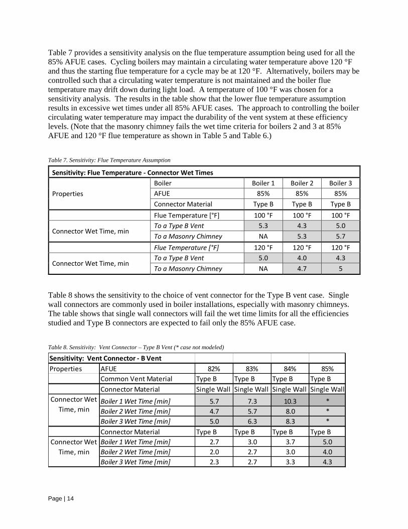
Table 7 provides a sensitivity analysis on the flue temperature assumption being used for all the
85% AFUE cases. Cycling boilers may maintain a circulating water temperature above 120 °F
and thus the starting flue temperature for a cycle may be at 120 °F. Alternatively, boilers may be
controlled such that a circulating water temperature is not maintained and the boiler flue
temperature may drift down during light load. A temperature of 100 °F was chosen for a
sensitivity analysis. The results in the table show that the lower flue temperature assumption
results in excessive wet times under all 85% AFUE cases. The approach to controlling the boiler
circulating water temperature may impact the durability of the vent system at these efficiency
levels. (Note that the masonry chimney fails the wet time criteria for boilers 2 and 3 at 85%
AFUE and 120 °F flue temperature as shown in Table 5 and Table 6.)
Table 7. Sensitivity: Flue Temperature Assumption
Sensitivity: Flue Temperature - Connector Wet Times
Properties
Boiler Boiler 1 Boiler 2 Boiler 3
AFUE 85% 85% 85%
Connector Material Type B Type B Type B
Flue Temperature [°F] 100 °F 100 °F 100 °F
Connector Wet Time, min To a Type B Vent 5.3 4.3 5.0
To a Masonry Chimney NA 5.3 5.7
Flue Temperature [°F] 120 °F 120 °F 120 °F
Connector Wet Time, min To a Type B Vent 5.0 4.0 4.3
To a Masonry Chimney NA 4.7 5
Table 8 shows the sensitivity to the choice of vent connector for the Type B vent case. Single
wall connectors are commonly used in boiler installations, especially with masonry chimneys.
The table shows that single wall connectors will fail the wet time limits for all the efficiencies
studied and Type B connectors are expected to fail only the 85% AFUE case.
Table 8. Sensitivity: Vent Connector – Type B Vent (* case not modeled)
Sensitivity: Vent Connector - B Vent
Properties AFUE 82% 83% 84% 85%
Common Vent Material Type B Type B Type B Type B
Connector Material Single Wall Single Wall Single Wall Single Wall
Boiler 1 Wet Time [min] 5.7 7.3 10.3 *
Boiler 2 Wet Time [min] 4.7 5.7 8.0 *
Boiler 3 Wet Time [min] 5.0 6.3 8.3 *
Connector Material Type B Type B Type B Type B
Boiler 1 Wet Time [min] 2.7 3.0 3.7 5.0
Boiler 2 Wet Time [min] 2.0 2.7 3.0 4.0
Boiler 3 Wet Time [min] 2.3 2.7 3.3 4.3
Connector Wet
Time, min
Connector Wet
Time, min

Page | 15
Table 9 provides the same sensitivity analysis for masonry chimneys. Again, all single wall
connector cases fail for all efficiencies studied. The Type B connectors pass the 82-84% cases
but fail the 85% case. However, recall from Table 6 that the masonry chimney itself fails the wet
time criteria for all cases.
Table 9. Sensitivity: Vent Connector - Masonry Chimney (* case not modeled)
Sensitivity: Vent Connector - Masonry Chimney
Properties AFUE 82% 83% 84% 85%
Chimney Material Masonry Masonry Masonry Masonry
Connector Material Single Wall Single Wall Single Wall Single Wall
Connector Wet Time, min
Boiler 1 Wet Time [min] NA NA NA NA
Boiler 2 Wet Time [min] 4.7 5.7 7.7 *
Boiler 1 Wet Time [min] 5.0 6.0 8.0 *
Connector Material Type B Type B Type B Type B
Connector Wet Time, min
Boiler 1 Wet Time [min] NA NA NA NA
Boiler 2 Wet Time [min] 2.3 2.7 3.3 4.7
Boiler 1 Wet Time [min] 2.7 3.0 3.7 5.0
Page | 16
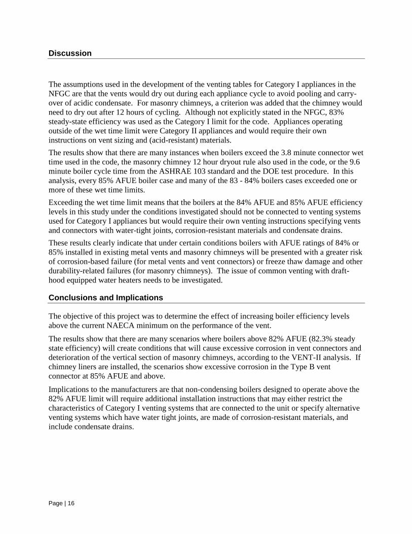
Discussion
The assumptions used in the development of the venting tables for Category I appliances in the
NFGC are that the vents would dry out during each appliance cycle to avoid pooling and carry-
over of acidic condensate. For masonry chimneys, a criterion was added that the chimney would
need to dry out after 12 hours of cycling. Although not explicitly stated in the NFGC, 83%
steady-state efficiency was used as the Category I limit for the code. Appliances operating
outside of the wet time limit were Category II appliances and would require their own
instructions on vent sizing and (acid-resistant) materials.
The results show that there are many instances when boilers exceed the 3.8 minute connector wet
time used in the code, the masonry chimney 12 hour dryout rule also used in the code, or the 9.6
minute boiler cycle time from the ASHRAE 103 standard and the DOE test procedure. In this
analysis, every 85% AFUE boiler case and many of the 83 - 84% boilers cases exceeded one or
more of these wet time limits.
Exceeding the wet time limit means that the boilers at the 84% AFUE and 85% AFUE efficiency
levels in this study under the conditions investigated should not be connected to venting systems
used for Category I appliances but would require their own venting instructions specifying vents
and connectors with water-tight joints, corrosion-resistant materials and condensate drains.
These results clearly indicate that under certain conditions boilers with AFUE ratings of 84% or
85% installed in existing metal vents and masonry chimneys will be presented with a greater risk
of corrosion-based failure (for metal vents and vent connectors) or freeze thaw damage and other
durability-related failures (for masonry chimneys). The issue of common venting with draft-
hood equipped water heaters needs to be investigated.
Conclusions and Implications
The objective of this project was to determine the effect of increasing boiler efficiency levels
above the current NAECA minimum on the performance of the vent.
The results show that there are many scenarios where boilers above 82% AFUE (82.3% steady
state efficiency) will create conditions that will cause excessive corrosion in vent connectors and
deterioration of the vertical section of masonry chimneys, according to the VENT-II analysis. If
chimney liners are installed, the scenarios show excessive corrosion in the Type B vent
connector at 85% AFUE and above.
Implications to the manufacturers are that non-condensing boilers designed to operate above the
82% AFUE limit will require additional installation instructions that may either restrict the
characteristics of Category I venting systems that are connected to the unit or specify alternative
venting systems which have water tight joints, are made of corrosion-resistant materials, and
include condensate drains.

Page | 17
References
AGA/NFPA. ANSI Z223.1-2012/NFPA 54-2012. National Fuel Gas Code. 2012 Edition.
American Gas Association and the National Fire Protection Association.
ANSI/ASHRAE Standard 103-2007, Method of Testing for Annual Fuel Utilization Efficiency of
Residential Central Furnaces and Boilers, American Society of Heating, Refrigerating, and Air
Conditioning Engineers 2007.
Detty, DW, Mawlakar, S.R, and McKeown, SW. August 1998. Topical Report: VENT-II Users
Guide, Version 5.0. Battelle, Columbus Ohio, for Gas Research Institute
Paul, Darrell. GRI-02/0128. July 2002. Topical Report: A Synopsis of Gas Appliance Venting
Research and its Relevance to Higher Efficiency Gas Furnaces and Boilers, Battelle, Columbus
Ohio, for Gas Technology Institute

Page | 18
List of Acronyms
Acronym Description
AGA American Gas Association
AHRI Air Conditioning, Heating, and Refrigeration Institute
DOE Department of Energy
GTI Gas Technology Institute
GRI Gas Research Institute
HVAC Heating, Ventilation, and Air Conditioning
NFGC National Fuel Gas Code

Page | 19
Appendix A – List of Assumptions and Specifications
Boiler Capacity
Boiler # Capacity
1 71 kBtu/h
2 286 kBtu/h
3 283 kBtu/h
Damper Specifications
Settings used for all boiler simulations.
Opening Time 15 sec
Closing Time 15 sec
Ratio of Open Damper Area
to Vent Area
0.86
Ratio of Closed Damper Area
to Vent Area
0.04
Angle b/t Open and Closed
Damper
90°
Vent Specifications
Configuration
Used for all boiler simulations.
Vent Height 16 ft.
Vent Lateral – Type B
Vent Lateral – Masonry
10 ft.
3 ft.
Connector Rise 1 ft.

Page | 20
Ambient Temperatures
Used for all boiler simulations
Connector 60 °F
Lateral 60 °F
Common – Lowest 10 feet 60 °F
Common – Next 2 feet 60 °F
Common – Last 3 feet 42 °F
Vent Requirements and Assumptions
NFGC Vent Connector Requirements
Connector Type Minimum Thickness Requirement
Single Wall Galvanized
Steel
0.018 in.
Type B None; VENT-II default thickness used in place
Source: 2012 NFGC Section 12.11.2.3 Material requirements for category 1 appliance vent connectors
VENT II Type B Section Default Thickness and Materials
Connector
Type
Thickness
Requirement
Total
Thickness
Outer
Layer
Thickness
Outer
Layer
Material
Inner
Layer
Thickness
Inner
Layer
Material
Air Gap
Thickness
Type B No thickness
requirement
0.25 in. 0.019 in. Galvanized
Steel
0.012 Aluminum ~0.22
Source: VENT-II User Manual
VENT II Masonry Chimney Defaults
M1- Masonry
Outer Layer material Brick
Outer Layer Thickness 4 in.
Inner Layer Material Clay Tile
Inner Layer Thickness 0.75 in.
Gap Material Air
Source: VENT-II User Manual
Page | 21
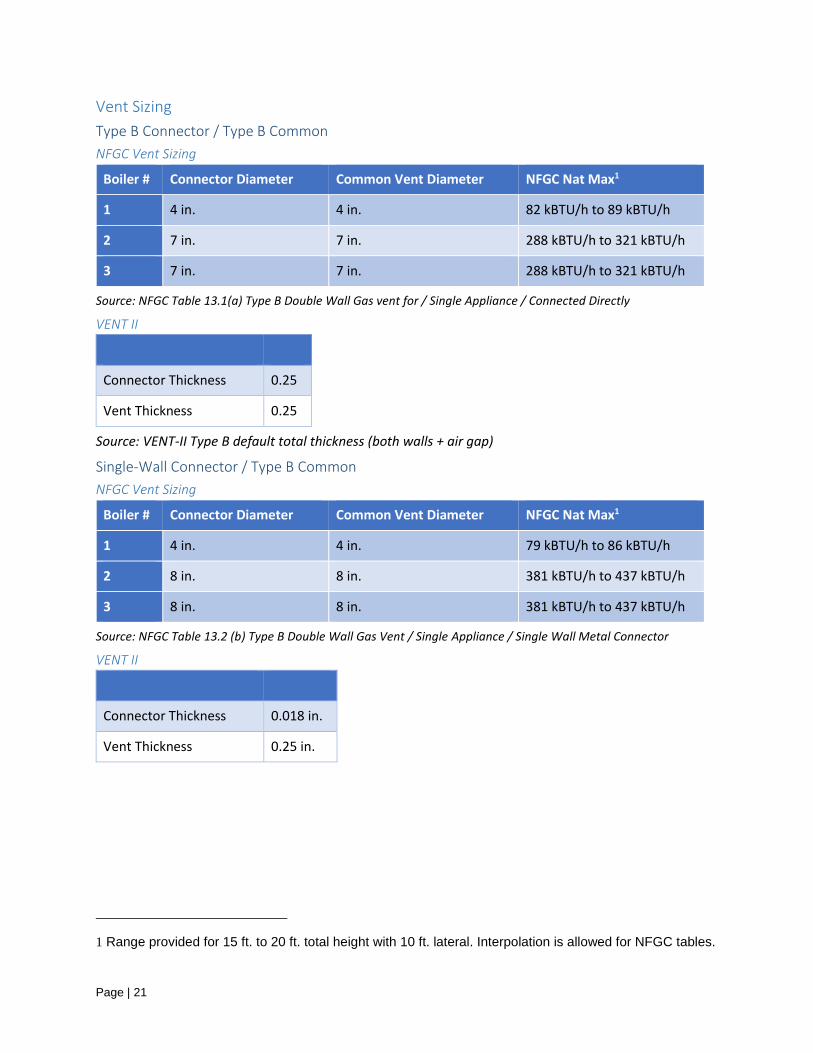
Vent Sizing
Type B Connector / Type B Common
NFGC Vent Sizing
Boiler # Connector Diameter Common Vent Diameter NFGC Nat Max1
1 4 in. 4 in. 82 kBTU/h to 89 kBTU/h
2 7 in. 7 in. 288 kBTU/h to 321 kBTU/h
3 7 in. 7 in. 288 kBTU/h to 321 kBTU/h
Source: NFGC Table 13.1(a) Type B Double Wall Gas vent for / Single Appliance / Connected Directly
VENT II
Connector Thickness 0.25
Vent Thickness 0.25
Source: VENT-II Type B default total thickness (both walls + air gap)
Single-Wall Connector / Type B Common
NFGC Vent Sizing
Boiler # Connector Diameter Common Vent Diameter NFGC Nat Max1
1 4 in. 4 in. 79 kBTU/h to 86 kBTU/h
2 8 in. 8 in. 381 kBTU/h to 437 kBTU/h
3 8 in. 8 in. 381 kBTU/h to 437 kBTU/h
Source: NFGC Table 13.2 (b) Type B Double Wall Gas Vent / Single Appliance / Single Wall Metal Connector
VENT II
Connector Thickness 0.018 in.
Vent Thickness 0.25 in.
1 Range provided for 15 ft. to 20 ft. total height with 10 ft. lateral. Interpolation is allowed for NFGC tables.

Page | 22
Type B Connector / Masonry Chimney
NFGC Vent Sizing
Boiler
#
Connector
Diameter
[in]
Minimum Internal
Area of Chimney [in2]
VENT II Common
Vent Circular
Liner Diameter
[in]
NFGC Nat Max1
1 5 in. 28 in2 6 in. 97 kBTU/h to 107 kBTU/h
2 8 in. 63 in2 9 in. 296 kBTU/h to 332 kBTU/h
3 8 in. 63 in2 9 in. 296 kBTU/h to 332 kBTU/h
Source: NFGC Table 13.2 (c) Masonry Chimney / Single Appliance / Type B Connector
VENT II
Connector Thickness 0.25 in.
Total Thickness 5.5 in.
Outer Wall [Brick] 4 in.
Air Space 0.75 in.
Inner 0.75 in.
Single-Wall Connector / Masonry Chimney
NFGC Vent Sizing
Boiler
#
Connector
Diameter
[in]
Minimum Internal
Area of Chimney [in2]
VENT II Common
Vent Circular
Liner Diameter
[in]
NFGC Nat Max1
1 5 in. 28 in2 6 in. 96 kBTU/h to 105 kBTU/h
2 8 in. 63 in2 9 in. 294 kBTU/h to 330 kBTU/h
3 8 in. 63 in2 9 in. 294 kBTU/h to 330 kBTU/h
Source: NFGC Table 13.2 (d) Masonry Chimney / Single Appliance / Single-wall Metal Connector
VENT II
Connector Thickness 0.018 in.
Total Thickness 5.5 in.
Outer Wall [Brick] 4 in.

Page | 23
Air Space 0.75 in.
Inner 0.75 in.

Page | 24
Boiler Profiles
Boiler 1 – 120 °F Minimum Flue Outlet Temperature
Boiler 1 Flue Profile – Minimum Flue Temperature of 120 °F
Time [min] 82% AFUE 83% AFUE 84% AFUE 85% AFUE
0.00 120.00 120.00 120.00 120.00
0.64 226.56 209.74 194.31 177.02
1.91 302.66 273.82 247.38 217.74
3.18 328.95 295.96 265.71 231.81
4.45 339.49 304.84 273.07 237.45
5.72 343.55 308.25 275.90 239.62
6.99 344.97 309.45 276.89 240.38
8.25 346.02 310.33 277.62 240.94
9.60 348.00 312.00 279.00 242.00
11.26 276.88 252.11 229.40 203.94
13.07 238.94 220.16 202.95 183.65
14.87 210.59 196.29 183.18 168.48
16.67 188.94 178.05 168.07 156.89
18.48 172.58 164.28 156.67 148.13
20.28 160.22 153.87 148.05 141.52
22.09 150.80 145.94 141.48 136.48
23.89 143.56 139.84 136.43 132.61
25.70 137.99 135.15 132.55 129.63
27.50 133.51 131.37 129.42 127.23
29.31 129.93 128.36 126.92 125.31

Page | 25
Boiler 1 Flue Profile – Minimum Flue Temperature of 120 °F
Time [min] 82% AFUE 83% AFUE 84% AFUE 85% AFUE
31.11 127.08 125.96 124.94 123.79
32.92 124.81 124.05 123.35 122.57
34.72 123.08 122.60 122.15 121.65
36.53 121.72 121.45 121.20 120.92
38.33 120.74 120.62 120.51 120.39
40.13 120.00 120.00 120.00 120.00

Page | 26
Boiler 1 – 100 °F Minimum Flue Outlet Temperature
Boiler 1 Flue Profile – Minimum Flue Temperature of 100 °F
Time [min] 82% AFUE 83% AFUE 84% AFUE 85% AFUE
0.00 100.00 100.00 100.00 100.00
0.64 215.91 199.09 183.66 166.37
1.91 298.69 269.85 243.41 213.76
3.18 327.28 294.29 264.04 230.13
4.45 338.75 304.09 272.32 236.70
5.72 343.16 307.86 275.51 239.23
6.99 344.71 309.19 276.62 240.12
8.25 345.85 310.16 277.45 240.77
9.60 348.00 312.00 279.00 242.00
11.26 270.64 245.87 223.16 197.71
13.07 229.38 210.60 193.38 174.08
14.87 198.54 184.24 171.12 156.42
16.67 174.98 164.10 154.12 142.93
18.48 157.19 148.89 141.28 132.75

Page | 27
Boiler 1 Flue Profile – Minimum Flue Temperature of 100 °F
Time [min] 82% AFUE 83% AFUE 84% AFUE 85% AFUE
20.28 143.75 137.40 131.58 125.05
22.09 133.50 128.64 124.18 119.18
23.89 125.63 121.91 118.50 114.68
25.70 119.57 116.73 114.13 111.21
27.50 114.69 112.56 110.60 108.41
29.31 110.80 109.23 107.80 106.18
31.11 107.70 106.58 105.56 104.41
32.92 105.23 104.47 103.77 102.99
34.72 103.35 102.87 102.42 101.92
36.53 101.87 101.60 101.35 101.07
38.33 100.80 100.68 100.58 100.46
40.13 100.00 100.00 100.00 100.00
Page | 28
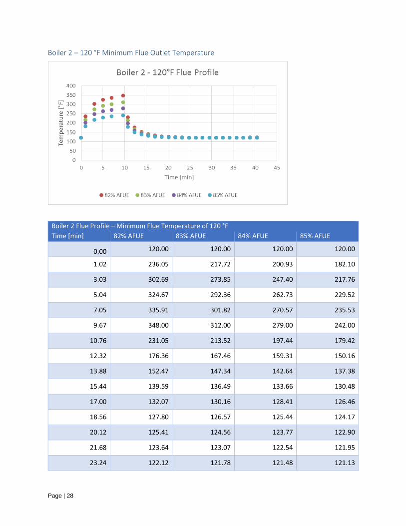
Boiler 2 – 120 °F Minimum Flue Outlet Temperature
Boiler 2 Flue Profile – Minimum Flue Temperature of 120 °F
Time [min] 82% AFUE 83% AFUE 84% AFUE 85% AFUE
0.00 120.00 120.00 120.00 120.00
1.02 236.05 217.72 200.93 182.10
3.03 302.69 273.85 247.40 217.76
5.04 324.67 292.36 262.73 229.52
7.05 335.91 301.82 270.57 235.53
9.67 348.00 312.00 279.00 242.00
10.76 231.05 213.52 197.44 179.42
12.32 176.36 167.46 159.31 150.16
13.88 152.47 147.34 142.64 137.38
15.44 139.59 136.49 133.66 130.48
17.00 132.07 130.16 128.41 126.46
18.56 127.80 126.57 125.44 124.17
20.12 125.41 124.56 123.77 122.90
21.68 123.64 123.07 122.54 121.95
23.24 122.12 121.78 121.48 121.13

Page | 29
Boiler 2 Flue Profile – Minimum Flue Temperature of 120 °F
Time [min] 82% AFUE 83% AFUE 84% AFUE 85% AFUE
24.81 121.11 120.93 120.77 120.59
26.37 120.69 120.58 120.48 120.37
27.93 120.41 120.34 120.28 120.22
29.49 120.34 120.29 120.24 120.18
31.05 120.08 120.07 120.06 120.04
32.61 120.00 120.00 120.00 120.00
34.17 120.95 120.80 120.66 120.51
35.73 121.32 121.11 120.92 120.71
37.29 121.50 121.26 121.04 120.80
38.85 121.71 121.44 121.19 120.91
40.42 121.66 121.40 121.16 120.89

Page | 30
Boiler 2 – 100 °F Minimum Flue Outlet Temperature
Boiler 2 Flue Profile – Minimum Flue Temperature of 100 °F
Time [min] 82% AFUE 83% AFUE 84% AFUE 85% AFUE
0.00 100.00 100.00 100.00 100.00
1.02 226.23 207.90 191.11 172.28
3.03 298.72 269.87 243.43 213.78
5.04 322.63 290.31 260.69 227.47
7.05 334.85 300.76 269.51 234.47
9.67 348.00 312.00 279.00 242.00
10.76 220.79 203.26 187.18 169.16
12.32 161.31 152.41 144.25 135.10
13.88 135.32 130.19 125.49 120.22
15.44 121.31 118.21 115.38 112.20
17.00 113.12 111.22 109.47 107.51
18.56 108.49 107.25 106.13 104.86
20.12 105.89 105.03 104.25 103.37
21.68 103.96 103.39 102.86 102.27
23.24 102.30 101.97 101.66 101.32

Page | 31
Boiler 2 Flue Profile – Minimum Flue Temperature of 100 °F
Time [min] 82% AFUE 83% AFUE 84% AFUE 85% AFUE
24.81 101.21 101.03 100.87 100.69
26.37 100.75 100.64 100.54 100.43
27.93 100.44 100.38 100.32 100.25
29.49 100.37 100.32 100.27 100.21
31.05 100.09 100.07 100.06 100.05
32.61 100.00 100.00 100.00 100.00
34.17 101.03 100.88 100.74 100.59
35.73 101.44 101.23 101.04 100.82
37.29 101.63 101.39 101.18 100.93
38.85 101.86 101.59 101.34 101.06
40.42 101.80 101.54 101.30 101.03
Page | 32
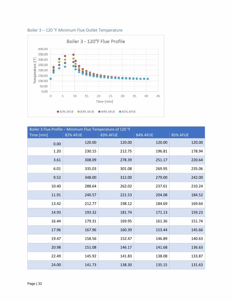
Boiler 3 – 120 °F Minimum Flue Outlet Temperature
Boiler 3 Flue Profile – Minimum Flue Temperature of 120 °F
Time [min] 82% AFUE 83% AFUE 84% AFUE 85% AFUE
0.00 120.00 120.00 120.00 120.00
1.20 230.15 212.75 196.81 178.94
3.61 308.09 278.39 251.17 220.64
6.01 335.03 301.08 269.95 235.06
9.52 348.00 312.00 279.00 242.00
10.40 288.64 262.02 237.61 210.24
11.91 240.57 221.53 204.08 184.52
13.42 212.77 198.12 184.69 169.64
14.93 193.32 181.74 171.13 159.23
16.44 179.31 169.95 161.36 151.74
17.96 167.96 160.39 153.44 145.66
19.47 158.56 152.47 146.89 140.63
20.98 151.08 146.17 141.68 136.63
22.49 145.92 141.83 138.08 133.87
24.00 141.73 138.30 135.15 131.63

Page | 33
Boiler 3 Flue Profile – Minimum Flue Temperature of 120 °F
Time [min] 82% AFUE 83% AFUE 84% AFUE 85% AFUE
25.51 137.48 134.72 132.19 129.35
27.02 133.79 131.61 129.61 127.38
28.53 130.75 129.06 127.50 125.75
30.04 128.66 127.30 126.04 124.64
31.55 126.80 125.72 124.74 123.64
33.07 125.15 124.34 123.59 122.76
34.58 123.78 123.18 122.63 122.02
36.09 122.54 122.14 121.77 121.36
37.60 121.37 121.15 120.95 120.73
39.11 120.65 120.55 120.45 120.35
40.62 120.00 120.00 120.00 120.00

Page | 34
Boiler 3 – 100 °F Minimum Flue Outlet Temperature
Boiler 3 Flue Profile – Minimum Flue Temperature of 100 °F
Time [min] 82% AFUE 83% AFUE 84% AFUE 85% AFUE
0.00 100.00 100.00 100.00 100.00
1.20 219.81 202.42 186.47 168.60
3.61 304.59 274.89 247.66 217.14
6.01 333.89 299.94 268.81 233.92
9.52 348.00 312.00 279.00 242.00
10.40 283.44 256.81 232.40 205.03
11.91 231.15 212.11 194.66 175.09
13.42 200.90 186.26 172.83 157.78
14.93 179.75 168.17 157.56 145.66
16.44 164.51 155.15 146.56 136.94
17.96 152.17 144.59 137.65 129.87
19.47 141.94 135.85 130.27 124.02
20.98 133.81 128.90 124.40 119.36
22.49 128.19 124.10 120.35 116.14
24.00 123.63 120.20 117.06 113.53
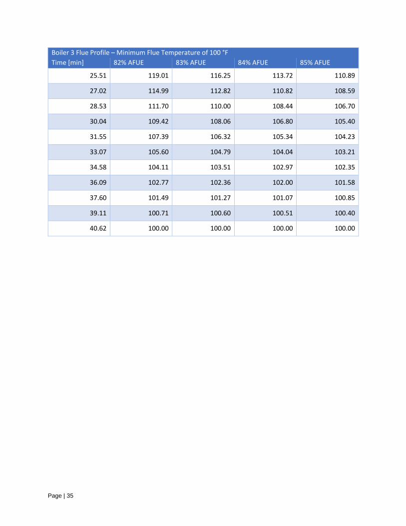
Page | 35
Boiler 3 Flue Profile – Minimum Flue Temperature of 100 °F
Time [min] 82% AFUE 83% AFUE 84% AFUE 85% AFUE
25.51 119.01 116.25 113.72 110.89
27.02 114.99 112.82 110.82 108.59
28.53 111.70 110.00 108.44 106.70
30.04 109.42 108.06 106.80 105.40
31.55 107.39 106.32 105.34 104.23
33.07 105.60 104.79 104.04 103.21
34.58 104.11 103.51 102.97 102.35
36.09 102.77 102.36 102.00 101.58
37.60 101.49 101.27 101.07 100.85
39.11 100.71 100.60 100.51 100.40
40.62 100.00 100.00 100.00 100.00