In-Reactor Creep of Zirconium Alloys - ANT International · In-Reactor Creep of Zirconium Alloys ....
39
I N -R EACTOR C REEP OF Z IRCONIUM A LLOYS – 2009 © September 2009 Advanced Nuclear Technology International Krongjutarvägen 2C, SE-730 50 Skultuna Sweden [email protected] www.antinternational.com In-Reactor Creep of Zirconium Alloys Authors Ron Adamson Zircology Plus, Fremont, CA, USA Friedrich Garzarolli Fürth, Germany Charles Patterson Clovis, CA, USA Technical Editor Ron Adamson Zircology Plus, Fremont, CA, USA
Transcript of In-Reactor Creep of Zirconium Alloys - ANT International · In-Reactor Creep of Zirconium Alloys ....

I N - R E A C T O R C R E E P O F Z I R C O N I U M A L L O Y S – 2 0 0 9
© September 2009
Advanced Nuclear Technology International
Krongjutarvägen 2C, SE-730 50 Skultuna
Sweden
www.antinternational.com
In-Reactor Creep of Zirconium Alloys
Authors
Ron Adamson Zircology Plus, Fremont, CA, USA
Friedrich Garzarolli Fürth, Germany
Charles Patterson Clovis, CA, USA
Technical Editor
Ron Adamson Zircology Plus, Fremont, CA, USA

I N - R E A C T O R C R E E P O F Z I R C O N I U M A L L O Y S – 2 0 0 9
Disclaimer
The information presented in this report has been compiled and analysed by
Advanced Nuclear Technology International Europe AB (ANT International®)
and its subcontractors. ANT International has exercised due diligence in this work,
but does not warrant the accuracy or completeness of the information.
ANT International does not assume any responsibility for any consequences
as a result of the use of the information for any party, except a warranty
for reasonable technical skill, which is limited to the amount paid for this assignment
by each ZIRAT/IZNA programme member.
Copyright © Advanced Nuclear Technology International Europe AB, ANT International, 2009.
I(IX)

I N - R E A C T O R C R E E P O F Z I R C O N I U M A L L O Y S – 2 0 0 9
Acknowledgment
The authors gratefully acknowledge the many helpful comments, review of the text and encouragement given by Peter Rudling. Also, a sanity check, general review and technical comments were graciously provided by Dr. Malcolm Griffiths and his colleagues at AECL. Their expert contributions are much appreciated. Any errors or omissions in the report are solely the responsibility of the ZIRAT team.
Copyright © Advanced Nuclear Technology International Europe AB, ANT International, 2009.
II(IX)
I N - R E A C T O R C R E E P O F Z I R C O N I U M A L L O Y S – 2 0 0 9
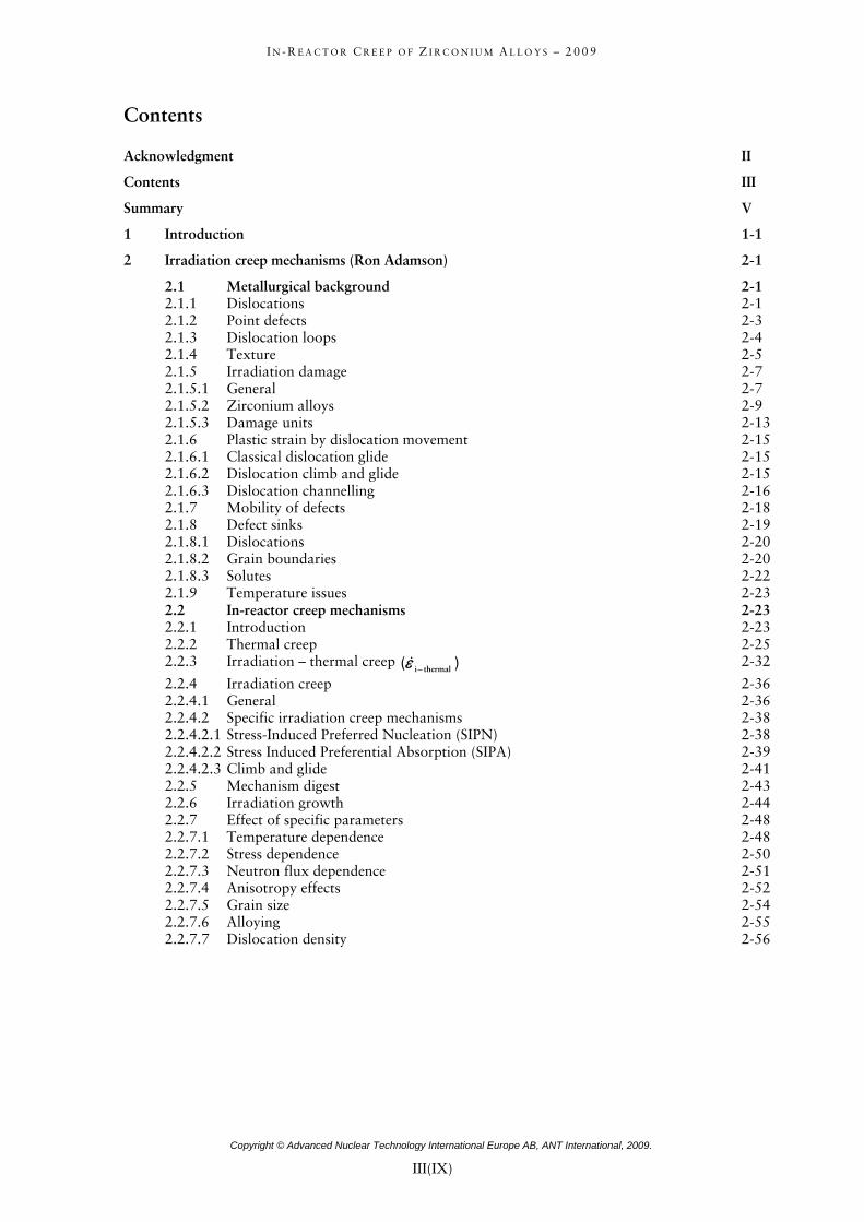
Contents
Acknowledgment II Contents III Summary V 1 1-1 Introduction
2 2-1 Irradiation creep mechanisms (Ron Adamson)
2.1 2-1 Metallurgical background2.1.1 2-1 Dislocations2.1.2 2-3 Point defects2.1.3 2-4 Dislocation loops2.1.4 2-5 Texture2.1.5 2-7 Irradiation damage2.1.5.1 2-7 General2.1.5.2 2-9 Zirconium alloys2.1.5.3 2-13 Damage units2.1.6 2-15 Plastic strain by dislocation movement2.1.6.1 2-15 Classical dislocation glide2.1.6.2 2-15 Dislocation climb and glide2.1.6.3 2-16 Dislocation channelling2.1.7 2-18 Mobility of defects2.1.8 2-19 Defect sinks2.1.8.1 2-20 Dislocations2.1.8.2 2-20 Grain boundaries2.1.8.3 2-22 Solutes2.1.9 2-23 Temperature issues2.2 2-23 In-reactor creep mechanisms2.2.1 2-23 Introduction2.2.2 2-25 Thermal creep2.2.3 Irradiation – thermal creep )( thermali−ε& 2-32 2.2.4 2-36 Irradiation creep2.2.4.1 2-36 General2.2.4.2 2-38 Specific irradiation creep mechanisms2.2.4.2.1 2-38 Stress-Induced Preferred Nucleation (SIPN)2.2.4.2.2 2-39 Stress Induced Preferential Absorption (SIPA)2.2.4.2.3 2-41 Climb and glide2.2.5 2-43 Mechanism digest2.2.6 2-44 Irradiation growth2.2.7 2-48 Effect of specific parameters2.2.7.1 2-48 Temperature dependence2.2.7.2 2-50 Stress dependence2.2.7.3 2-51 Neutron flux dependence2.2.7.4 2-52 Anisotropy effects2.2.7.5 2-54 Grain size2.2.7.6 2-55 Alloying2.2.7.7 2-56 Dislocation density
Copyright © Advanced Nuclear Technology International Europe AB, ANT International, 2009.
III(IX)

I N - R E A C T O R C R E E P O F Z I R C O N I U M A L L O Y S – 2 0 0 9
3 3-1 Available data on in-reactor creep and deduced correlations (Friedrich Garzarolli)
3.1 3-1 Available data on in-reactor creep and principle analysis approach3.2 3-5 Flux dependence of in-reactor creep3.3 3-8 Stress dependency of in-reactor creep3.4 3-14 Temperature dependence of in-reactor creep3.5 3-22 Anisotropy of in-reactor creep3.6 3-29 Primary in-reactor creep3.7 3-33 Alloying element dependence of in-reactor creep3.8 3-37 Microstructure dependence of in-reactor creep3.8.1 3-37 Grain size dependence3.8.2 3-41 Dependence of CW and degree of recrystallisation3.9 3-45 In-reactor creep behaviour of commercially available alloys
4 4-1 Creep models (Charles Patterson)
4.1 4-1 Introduction4.2 4-2 Creep models for continuous, uniform loading4.3 4-29 Creep models for variable loading4.4 4-36 Engineering application
5 5-1 References
Appendix A - In-reactor stress relaxation tests A-1 Appendix B - Uniaxial in-reactor creep tests B-1 Appendix C - Biaxial in-reactor creep tests C-1 Appendix D - Dimensional changes of PWR fuel rods D-1 Appendix E - Uniaxial proton accelerator creep tests E-1 Appendix F – References F-1 Acronyms and expressions Unit conversion
Copyright © Advanced Nuclear Technology International Europe AB, ANT International, 2009.
IV(IX)

I N - R E A C T O R C R E E P O F Z I R C O N I U M A L L O Y S – 2 0 0 9
Summary
General
In this STR we have attempted to summarize data and mechanisms by addressing the variables that are known to affect irradiation creep. Knowing that the creep processes are affected by interacting variables, we have wherever possible, particularly in the Section 3, attempted to examine one variable with the other variables fixed. However, in many cases, maybe even most cases, the experimental data on in-reactor creep contains uncontrolled variables, which confound the data interpretation. Acknowledging these limitations, a number of conclusions are reached which give insight into the uses of data, mechanisms and models to assess in-service performance of reactor components.
Mechanisms
Creep is plastic deformation occurring as a constant volume process, normally at low stresses below the yield stress. For materials in an irradiation field, the most important for purposes of this STR being the neutron environment of a nuclear reactor, the deformation occurs by the motion of dislocations and irradiation-produced defects under the influence of stress. Neutron irradiation produces large quantities of point defects – vacancies and SIAs (self interstitial atoms) – which migrate to and collect at various sinks. Due to the anisotropy of the zirconium crystal lattice, motion of both dislocations and SIAs is anisotropic, preferring to occur parallel to the basal plane in the <a> directions of the lattice. Dislocations are sinks for both vacancies and SIAs, but normally it is considered that an edge dislocation attracts SIAs more than vacancies. Dislocations produced by deformation and by irradiation lie on both basal and prism planes. Because of the diffusional anisotropy of SIAs, they tend to be absorbed by dislocations lying on prism planes. The diffusion of vacancies is isotropic, and they tend to be absorbed preferentially by dislocations lying on basal planes. Similarly, SIAs tend to be absorbed at grain boundaries oriented parallel to prism planes and vacancies on boundaries parallel to basal planes. Absorption of either vacancies or SIAs at dislocations of grain boundaries causes plastic strain; positive for SIAs and negative for vacancies. If the absorptions occurred randomly and in non-biased fashion, the net strain would be zero; however in zirconium alloys the built-in anisotropy results in separate positive and negative strains, and in constant volume deformation. Also, in addition to the natural anisotropy of the zirconium crystal lattice, another factor is the concept that anisotropic diffusion is enhanced by stress.
Many mechanisms of irradiation creep have been proposed, as discussed in Section 2. No single mechanism has been accepted as the dominating mechanism, and very likely several processes contribute simultaneously. The two most prominent mechanisms are Stress Induced Preferential Absorption (SIPA) and climb and glide. SIPA assumes a bias of the motion of vacancies and SIAs to dislocations depending on the orientation of the Burgers vectors with respect to the applied shear stress. There are several variations of SIPA, including the elasto-diffusion modification which invokes the effect of stress on the diffusion anisotropy itself. Elastodiffusion appears to have the strongest effect on creep within the SIPA “family”.
The most straightforward irradiation creep mechanism is the climb and glide mechanism, by which deformation-producing dislocations are aided in bypassing obstacles to their motion by irradiation produced point defects. As long as an individual dislocation attracts a net flux of either vacancies or SIAs, it can “climb around” a barrier and under the influence of an applied stress, glide to the next barrier, thereby producing strain and eventually cause a slip step at the material surface. The weak dependence of creep rate on dislocation density suggests that glide may not be the main strain-generating process.
A further contributor to the strain measured in a creep experiment is irradiation growth. Although not strictly in the “creep” category because it occurs in the absence of an applied stress, it is inevitably measured as part of the overall strain in all in-reactor experiments, except for bent beam stress relaxation tests. Irradiation growth results from mechanisms similar to irradiation creep in that it is dependent on the anisotropic properties of the zirconium crystal lattice. It is discussed briefly in Section 2.2.6.
Copyright © Advanced Nuclear Technology International Europe AB, ANT International, 2009.
V(IX)

I N - R E A C T O R C R E E P O F Z I R C O N I U M A L L O Y S – 2 0 0 9
Data correlations
Creep experiments in a neutron-irradiation environment have been conducted since the early 1960’s, and continue today. Since creep without irradiation tends to have a relatively high initial rate, and since irradiation damage builds up with time, the creep curve (strain versus time or fluence) is usually divided into primary and a secondary stages, as shown in (Figure 1-4) and (Figure 3-1). Whether or not true time “steady state” creep rate is obtained in-reactor is problematic, but in any cases it is assumed for the analysis of the important parameters given in Section 3. A tertiary stage is not reached except in very rare localized high stress cases.
In-reactor creep of any component or specimen consists of three components: 1) thermal creep (which in most practical cases is small, and in all cases is different than thermal creep of unirradiated material), 2) true irradiation creep, and 3) irradiation growth. The most common practice is to assume that the three components are independent and additive, although from a mechanistic view this is questionable. In the data analysis Section 3 of this report, only in-reactor creep has been analysed, without any deviation in a thermal and irradiation creep component, but any irradiation growth had been subtracted from the experimental creep measurements.
The steady state creep rate, ε& , is most often expressed as a function of variables:
),,,,,,( AGfefdtd RTnp ρσφεε
−==&
Q
and in-reactor strain, ε, is often expressed for a specific alloy and alloy condition as:
RTnm etA−
= σφε )(Q
where p, n and m are constants and
φ is the neutron flux, n/m2/s or dpa/s
σ is the applied stress, MPa
t is the time, s
Q is the activation energy, cal/mole
Q/R is the activation temperature, K
R is the universal gas constant, 1.98 cal./K/mole
T is the temperature, K
f is a texture parameter
G is the grain size
ρ is a parameter related to the dislocation density and degree of CW
A is a metallurgical factor for a specific alloy
For an analysis of the different effects on in-reactor creep about 900 literature data were collected and listed with the test parameters stress, temperature and flux, as well as the important material parameters in the Appendix. If, as very often is the case, some of the important material parameters had not been reported they were estimated.
Many parameters including neutron flux and fluence influence primary in-reactor creep. It is probably most practicable to correlate the primary creep to the secondary creep rate as shown in Section 3.6.
Copyright © Advanced Nuclear Technology International Europe AB, ANT International, 2009.
VI(IX)

I N - R E A C T O R C R E E P O F Z I R C O N I U M A L L O Y S – 2 0 0 9
Using large amounts of data, and normalizing the data as described in Section 3, it is determined that in the temperature range 275-390 ºC (548-663 K), flux in the range 0.50-50 x 1013 n/cm2/s, E>1 MeV, and independent of the direction of creep, material composition and material condition, the flux dependency, p, is 0.85. It is noted in Section 2 that purely irradiation creep mechanisms would predict p=1, but the inevitable contributions of thermal creep would tend to reduce the value below unity. For the very low neutron fluxes that occur at fuel bundle extremities, lower values of p would be expected.
Analysis of data, normalized as described in Section 3, concludes that the stress dependency of in-reactor creep is linear, n=1, in the most relevant stress range of <10 to 200 MPA. This applies for temperatures in the range of 275-390 ºC (548-663 K), independent of direction of creep, flux, material composition and material condition. Mechanistic analyses, Section 2, predict a range of n-values from 1 to higher than 2. SIPA and elastodiffusion predict a linear stress dependency, but the favoured climb and glide mechanisms predict higher values of n.
The temperature dependence of in-reactor creep also has components based on thermal and irradiation processes. It is generally assumed that pure irradiation creep has only a small temperature dependence (often the process is called “athermal”), but thermal processes play an increasing large role at temperatures above about 300 ºC (573 K). At temperatures above about 350 ºC (623 K) thermally produced vacancies and annealing of small vacancy clusters compete with irradiation produced PDs (point defects), and by 400 °C (673 K) thermal processes dominate in-reactor creep. In all cases increasing temperature increases the creep rate. Analysis of a large amount of normalized data, Section 3, indicates that temperature dependency in the interesting range of 270-400 °C varies and depends on several important variables include cold work, Sn content, alloy content and fabrication history. The lowest temperature dependency is ascribed to heavily cold-worked Zircaloy-2 and -4, while the highest is for Zr 2.5 Nb CANDU pressure tubes. (It should be noted that the operating temperature of CANDU pressure tubes is generally below 310 °C (583 K)).
Several metallurgical factors influence creep. Disturbances in the regularity of the lattice such as caused by under- or over-sized atoms interfere with dislocation motion and act as sinks for irradiation-produced vacancies and SIAs. Of particular importance are the elements disturbing the regularity of the lattice and having appreciable solubility in Zr: Sn, Nb, and O, all of which increase the creep strength. On the other hand, an element having low solubility, S, has been shown to increase the creep strength of Zr1Nb alloys. The mechanism is not yet well defined, but is proposed to be a dislocation interaction effect. For unirradiated material, a significant strain aging effect due to O and C is observed, but irradiation appears to greatly lessen the effect.
GS and in some cases sub-GS (consisting of dislocation arrays) has been shown to influence creep, although there is not firm mechanistic understanding of the phenomena. In all cases dislocations, dislocation loops and grain boundaries each compete as sinks for the same irradiation-produced defects. Also grain shape is important, particularly in cold-worked Zr2.5Nb pressure tubes, where the effective width of grain can be very small (e.g., 0.3 μm). Bent beam stress relaxation experiments, which are pure creep without contributions from irradiation growth, indicate a mild increase in creep rate with increasing GS above about 0.5 μm and Zr2.5Nb pressure tube data indicate an increase of creep rate with decreasing GS below 0.5 μm. Thus lowest in-reactor creep is to be expected at a GS of about 0.5 μm for extruded and cold drawn Zr2.5Nb. Section 3 analysis furthermore the creep behaviour of Zircaloy-2 and Zry-4 thin wall tubes and strips after normalization and indicates for this type of material a minimum in the creep rate versus GS curve at about 7μm, with increases in creep rate for either smaller or larger grains. Typical GS for BWR and PWR Zircaloys is in the range 2-10 μm.
Copyright © Advanced Nuclear Technology International Europe AB, ANT International, 2009.
VII(IX)

I N - R E A C T O R C R E E P O F Z I R C O N I U M A L L O Y S – 2 0 0 9
Cold working affects three metallurgical parameters: dislocation density, grain shape and texture (anisotropy), all of which can affect creep rate. The general observation is that cold worked or cold worked/stress relieved (SRA) zirconium alloys have higher creep rates than RXA alloys. Section 3 analyses predict for Zircaloys a moderate effect of cold work up to about 50% CW and then a large effect for >50% cw. Mechanistic analyses again are not firm on a quantitative effect of dislocation density, but most, including varieties of the SIPA mechanism, predict higher in-reactor creep rates with higher dislocation density. Stress relaxation experiments suggest a moderate dependency (ρ0.2), whereas for irradiation growth it is about ρ0.8.
Since the HCP crystal structure is anisotropic, many properties are expected to be anisotropic, and are. The often-preferred slip (glide) direction is <a> (prism slip), as is the preferred diffusion direction of SIAs, both occurring parallel to the basal plane. The prevalence of basal slip increases in irradiated material, but even so prism slip predominates at low stress, so the climb and glide mechanism predicts higher creep strain in the <a> direction (in Zircaloy components this is called the longitudinal direction), as does conventional and modified SIPA mechanisms. Although texture (as defined by basal pole figures) is nearly the same for RXA and SRA materials, the anisotropy as expressed by anisotropy coefficients are different for the two. For, for example, fuel rods, creep in the rod results in a rod length decrease for SRA material and an increase for RXA material. Section 3 analyses confirm that for uniaxial stress conditions, creep of Zircaloy components in the longitudinal direction is greater than in the transverse direction. Zr2.5Nb pressure tubes have different texture than most Zircaloy components, so the anisotropy is different than for Zircaloy components, but the basic principles are the same. From the derived correlations an equation was deduced that could be used to predict the in-reactor behaviour for temperatures, directions, materials, respectively conditions if no measured data are available. In (Table 3-4) predicted and measured creep behaviour for uniaxial longitudinal and biaxial in-reactor conditions for Zircaloy-2/4, ZIRLO and M5 are compared.
Models
Because in-reactor creep has so many different important components, equations and models are needed to enable useful predictions and analyses for current or future reactor components. In addition, as reviewed earlier, understanding of the basic creep mechanisms in anisotropic materials like zirconium alloys is still not strong enough to be truly predictive. Today, most models are empirical in nature, although some of the model constants are derived from specific in-reactor experiments. A good example of a long-term program aimed at co-development of models and important deformation features is given in the recent review by [Holt, 2008].
Mathematical modelling is somewhat simplified because in-reactor strains are generally small, less than a few percent, making for instance, the difference between true strain and engineering strain quite small. However, it is not possible to obtain a “one model to fit all” because of differences in material (alloy, texture, dislocation density, etc.), temperature, stress and even corrosion and hydriding for different reactor types and component designs.
Several models were examined that predict creep strain for continuous uniform loading over a range of conditions. It was shown that predicted creep rates could differ by an order of magnitude for the different creep models. This results from their different mathematical forms and from the different experiments (or lack of experiments) from which the model constants are derived. Results of parameter sensitivity and error propagation studies indicate that the most sensitive parameters also differ for the various models. The key parameters, however, generally include activation energy (Q), temperature (T), the exponent on time (t) or fast neutron flux (φ) dependence and stress to a lesser extent. It is clear from mechanism, data analysis and model studies that understanding the relationships between thermal and irradiation-driven creep is important.
Copyright © Advanced Nuclear Technology International Europe AB, ANT International, 2009.
VIII(IX)

I N - R E A C T O R C R E E P O F Z I R C O N I U M A L L O Y S – 2 0 0 9
Copyright © Advanced Nuclear Technology International Europe AB, ANT International, 2009.
IX(IX)
Under variable loading conditions (generally meaning a change in the stress magnitude or direction, but also including a change in temperature or neutron flux) a quantitative understanding of the physical processes which occur (primary creep, effects of stress reversals on SIPA mechanism, etc.) is needed but is lacking. Again mathematical modelling is required, and a choice among strain hardening, time (fluence) hardening, kinematic hardening or a combination of these models is required. Based on limited data, it appears that “strain hardening” is generally preferred but that a re-occurrence of primary creep upon stress reversal must be included in the model and suggests the need for kinematic hardening.
For even more complicated processes involving interactions between several components (fuel-cladding interactions (PCMI), GT-FA interactions, etc.) finite element analysis methods (FEM) are useful. To enable a creep model to be incorporated into FEM it needs to be simple enough to enable rapid calculation, be numerically stable, and be useable with state and history variables so it can be tracked as part of the solution process.
Future needs
Creep requirements vary for different reactor components and systems. In most cases, high creep strengths or resistance is desirable. For fuel rods at reactor start-up, high creep strength is needed to minimize creep-down strain, and at end of life is needed to increase the margin towards cladding liftoff due to fission gas release. But at intermediate burnups, it would be beneficial to have low primary creep resistance to reduce stresses and strain due to power transients (PCI loading). BWR channels benefit from high creep resistance to bow and bulge. PWR assembly components benefit by high axial creep resistance and by reduced anisotropic creep. CANDU pressure tubes benefit from high axial creep (and growth) resistance and high resistance to diametral sagging. All components benefit from reduction of variability of creep deformation.
A number of areas have been noted in this STR that would benefit from further experiments, modelling and understanding. These include:
• Mechanistic understanding in anisotropic zirconium alloys is weak. Refinement of current mechanistic models is needed, and equations produced which are useful in assessing effects of variables. Fundamental modelling, including computational science techniques, that can be verified by experiments would be useful.
• A more detailed understanding of the mix of thermal and irradiation creep as affected by temperature stress and flux is needed.
• The understanding (empirical or mechanistic) of the influence of GS is needed.
• The effect of very low and very high flux and fluence on reactor component creep is needed. A complementary issue is the effect of high fluence microstructure on creep rates, i.e., does creep undergo a “breakaway” as does irradiation growth.
• Specifically, details of the effects of H and S on creep are needed; generally, the effects of solutes (O, Sn, Nb, etc.) and alloying elements need more understanding.
• Much more information on the effects of changes in stress, stress direction and temperature on primary and steady state creep is needed.
• Subtle effects of texture and anisotropy on in-reactor deformation need more understanding.
• In-reactor experiments in which great care is taken to minimize the effects of material and environmental variables are needed.
The next step for ZIRAT in this area is to determine and assimilate the most pressing needs of ZIRAT customers for information and actions in the area of in-reactor deformation and to them suggest experiments, procedures, or material changes that address those needs.

I N - R E A C T O R C R E E P O F Z I R C O N I U M A L L O Y S – 2 0 0 9
1 Introduction
One of the most unique aspects of material behaviour in a nuclear power plant is the effect of radiation (mainly neutrons) on the dimensional stability (i.e., a change in dimensions during service) of the reactor components. Three phenomena may cause zirconium alloy fuel components to change their dimensions:
• Stress-free axial growth due to fast neutron irradiation.
• Hydriding of the Zr-alloy component.
• Creep in Zr-alloy components that are stressed.
Creep is defined as a time dependent change in dimension of a reactor component (or any material) under a stress, even if that stress is below the yield stress. The most important applications of creep are in in-reactor performance of fuel bundle components in Boiling Water Reactor (BWRs)/Pressurised Water Reactor (PWRs), Vodo-Vodyanoi Energetichesky Reactor (in English Water-Water Energetic Reactor) (VVER) and, Canadian Deuterium Uranium (CANDU) and Reaktor Bolshoi Mozhnosti Kanalov (in English Large Boiling Water Channel type reactor) (RBMK) pressure tubes.
Outward creep of the pressure tubes may limit the lifetime of the CANDU reactor.
Inward creep of cladding early in life and outward creep later in life are very important to fuel rod performance. A burnup limiting, fuel design, safety criterion in many countries requires the fuel clad outward creep rate to be no larger than the fuel pellet swelling rate. This requirement addresses the condition in which the rod internal pressure exceeds the primary system pressure due to a large release of fission gas and thereby induces outward cladding creep. If the rate of cladding creep exceeds the rate of pellet swelling, the pellet/clad gap will re-open; i.e., the cladding will liftoff from the fuel pellets, (Figure 1-1). Due to the low thermal conductivity of larger gaps, such liftoff can produce a thermal feedback effect that is defined as an “unanalyzed condition” in licensing space and could potentially lead to fuel failures. Thus, a fuel cladding with higher creep strength will result in larger margins towards liftoff.
Figure 1-1: Schematics showing how the pellet-cladding gap may change over burnup, (a) low burnup-a significant pellet-cladding gap exist, (b) intermediate burnup – no pellet-cladding gap and (c) high burnup in a high power rod with significant fission gas release – reopening of the pellet-cladding gap.
Copyright © Advanced Nuclear Technology International Europe AB, ANT International, 2009.
1-1(1-9)=

I N - R E A C T O R C R E E P O F Z I R C O N I U M A L L O Y S – 2 0 0 9
Also fuel rods, PWR/VVER Guide Tubes (GT), GT assemblies, and BWR channels bow by a combination of creep and growth. Specifically, creep strength of the PWR GTs is to a large extent involved in the Fuel Assembly (FA) bowing mechanisms, (Figure 1-2). If we compare two similar hypothetical fuel assembly designs (thus, the fuel assembly stiffness is the same) with the same GT compressive forces but with GTs with different creep strength both designs would bow to the same degree in the reactor. However, in the case of the low creep strength GT material the fuel assembly distortion would remain after the fuel assembly is removed from the core On the other hand, the fuel assembly with GTs with high creep strength would become straight again after off –loading the assembly from the core (since the elastic distortion of the assembly in-core would fully relax after off-loading) BWR channels also creep (bulge) outward due to a pressure differential between the core flow region inside the channel and the core by-pass region outside the channel, (Figure 1-1). These bowing and bulging processes can limit bundle burnup by inhibiting control rod movement or by decreasing thermal margins in Loss of Coolant Accident (LOCA) or dryout/departure from nucleate boiling situations. Excessive FA bowing in PWRs has also resulted in grid damage during shuffling of FAs in refuelling outages. Also unloading of channels through the core grid can be complicated due to excessive bulging of BWR fuel channels.
Hydr
aulic
and b
uoya
nce l
ift for
ce
Figure 1-2: Schematics showing fuel assembly bowing. Increased guide tube growth may result in larger holding down forces (figures going from left to right). The first mode of bowing is C-shape (the second drawing from the left), while the second and third mode of bowing is S-shape and W-shape, respectively.
Copyright © Advanced Nuclear Technology International Europe AB, ANT International, 2009.
1-2(1-9)=
I N - R E A C T O R C R E E P O F Z I R C O N I U M A L L O Y S – 2 0 0 9
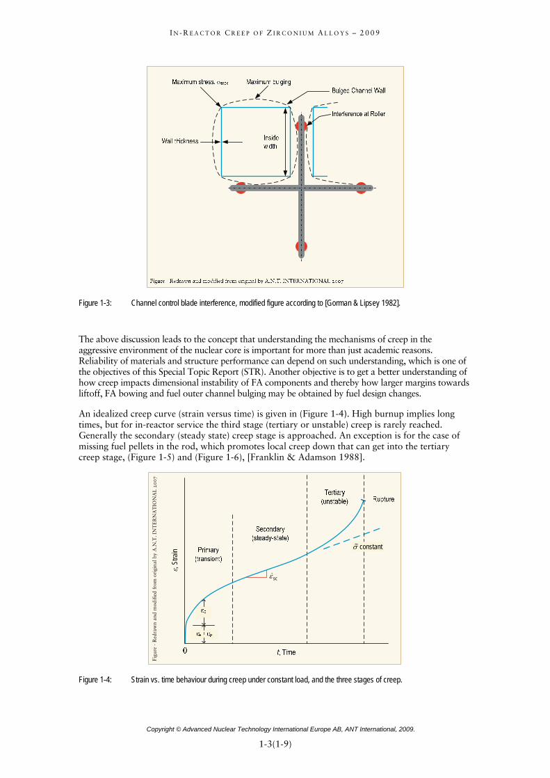
Figure 1-3: Channel control blade interference, modified figure according to [Gorman & Lipsey 1982].
The above discussion leads to the concept that understanding the mechanisms of creep in the aggressive environment of the nuclear core is important for more than just academic reasons. Reliability of materials and structure performance can depend on such understanding, which is one of the objectives of this Special Topic Report (STR). Another objective is to get a better understanding of how creep impacts dimensional instability of FA components and thereby how larger margins towards liftoff, FA bowing and fuel outer channel bulging may be obtained by fuel design changes.
An idealized creep curve (strain versus time) is given in (Figure 1-4). High burnup implies long times, but for in-reactor service the third stage (tertiary or unstable) creep is rarely reached. Generally the secondary (steady state) creep stage is approached. An exception is for the case of missing fuel pellets in the rod, which promotes local creep down that can get into the tertiary creep stage, (Figure 1-5) and (Figure 1-6), [Franklin & Adamson 1988].
cáÖìêÉ=JoÉÇê~ïå=~åÇ=ã
çÇáÑáÉÇ=Ñêçã=çêáÖáå~ä=Äó=^Kk
KqK=fk
qbok^qfl
k^i=OMMT
, Stra
in
scε&
constant ~σ
Figure 1-4: Strain vs. time behaviour during creep under constant load, and the three stages of creep.
Copyright © Advanced Nuclear Technology International Europe AB, ANT International, 2009.
1-3(1-9)=

I N - R E A C T O R C R E E P O F Z I R C O N I U M A L L O Y S – 2 0 0 9
Figure 1-5: Pictures showing fuel cladding collapse resulting in fuel perforation, [Franklin & Adamson 1988].
cáÖìêÉ=JoÉÇê~ïå=~åÇ=ã
çÇáÑáÉÇ=Ñêçã=çêáÖáå~ä=Äó=^Kk
KqK=fk
qbok^qfl
k^i=OMMV
Figure 1-6: Schematics showing that fuel densification caused fuel pellets hang-ups eventually resulting in fuel cladding collapse due to the much larger system than rod internal pressure.
In 2002, ZIRconium Alloy Technology (ZIRAT7) issued a Special Technical Report on “Dimensional Stability of Zirconium Alloys”, [Adamson & Rudling 2002/2003]. That report gave a broad overview of the available information on growth and creep. The present report concentrates on in-reactor creep under normal operating conditions of water cooled reactors and especially on the evaluation of the parameters affecting in-reactor creep of currently used and potential Zr alloys. Other important creep-related issues, like post-irradiation creep (dry storage) and creep driven LOCA and Reactivity Initiated Accident (RIA) will be covered in later Special Topic Reports (STRs).
Copyright © Advanced Nuclear Technology International Europe AB, ANT International, 2009.
1-4(1-9)=
I N - R E A C T O R C R E E P O F Z I R C O N I U M A L L O Y S – 2 0 0 9
Almost all materials experience dimensional changes in the core of reactors, if they are exposed to stress:
• Creep (by external stresses, residual stresses, and stresses build up by oxide layers formed due to corrosion in the coolant).
• Irradiation growth (relevant only for anisotropic materials, like Zr alloys).
• Swelling (small or zero for Zr-alloys).
• Volume increase by pickup of corrosion hydrogen (important especially for Zr alloys).
It is generally assumed that the different phenomena are independent; for instance, irradiation growth and irradiation creep are considered not to interact [Holt 2008] even though they are both driven by various agglomerations and diffusion of irradiation-produced Point Defects (PDs).
In-reactor creep is composed of two components:
• Thermal creep, which becomes important for Zr alloys only above 300-350 °C (depending on material and stress) and is affected by the irradiation induced microstructural changes. “Thermal creep” in-reactor is quite different from thermal creep of un-irradiated material.
• Irradiation creep, which is only weakly depends on temperature and is the major contributor in the temperature range of interest for water-cooled reactors.
The in-reactor creep depends primarily on stress, fast neutron flux, and temperature, but also on material conditions. The most important material condition parameters are:
• The solute alloying content (especially the O, Nb, and Sn content), which increases the in- reactor creep strength significantly, although its effect depends on temperature and stress. It should be mentioned that a high Sn+Nb+O content makes the component fabrication more difficult and that increasing Sn content and to a lesser extent increasing O content may increase corrosion and irradiation growth. The optimization of the composition is thus a very complex issue.
• The amount of cold work (CW), which increases the in-reactor creep rate and irradiation growth significantly, but decreases, for most PWR Zr-alloys, the corrosion resistance.
• The final annealing treatment. Stress relieve annealing (SRA), Partial Recrystallisation (PR), and, especially, full recrystallisation (RXA) reduce or eliminate the effect of CW, and sets the Grain Size (GS) and shape.
• The GS or effective GS, which is governed by (1) the material composition, (2) the temperature of β/α-phase transition and the quenching rate through the β/α-phase range, (3) the cold deformation prior to annealing, (4) the intermediate annealing, and (5) final annealing temperature. Highest in-reactor creep rates are seen at very low and very high GSs as discussed in Section 3. Whereas in case of the Zr2.5Nb pressure tubes the rate of β/α-phase transition and the extrusion process are most important for GS optimization, in case of the rather thin components of the FAs, highest creep resistance can be reached by a high intermediate annealing temperature, a rather low cold deformation, and a relatively high final annealing temperature. It should be noted that these parameters affect also other performance aspects, such as corrosion resistance, which makes material optimization a complex issue.
• The stress orientation in respect to the texture of the Zr alloy component, which plays also an important role. For tubing and channels, for instance, the highest in-reactor creep is usually seen if the Zr-alloys are stressed in the axial direction. Operation temperature has a larger effect on in-reactor creep in this direction than in tangential direction and the alloying effect is probably also different for in-reactor creep in axial direction.
Copyright © Advanced Nuclear Technology International Europe AB, ANT International, 2009.
1-5(1-9)=

I N - R E A C T O R C R E E P O F Z I R C O N I U M A L L O Y S – 2 0 0 9
Furthermore, the texture in (anisotropic) Zr alloys can cause an axial length change due to anisotropic in-reactor creep under a 2 to 1 tangential to axial stress ratio, as arises under a pressure difference (between system and rod internal pressure), before pellet-cladding contact, and some Pellet Cladding Mechanical Interactions (PCMIs) on components such as pressure tubes or fuel rod claddings.
In an isotropic material such as stainless steel, internally pressurised closed end tubing undergoes no length change (just a diameter increase and a wall thickness decrease). However in anisotropic Zr-alloys with textures typical of fuel rod tubing, internal pressure causes a decrease in length for RXA (recrystallised) material and an increase in length in CW or SRA (stress relieved) material. If the sign of the hoop stress is reversed, the respective length changes are reversed. (Figure 1-7) gives some representative data.
Figure 1-7: In-reactor creep of closed-end tubes with 2-1 ratio of hoop to axial stress. Note that the above tests were performed on tubes with an internal overpressure, which results in outward creep (contrary to what happens in a reactor). The above figure shows that tube creep out (indicated by a positive tangential creep strain) shortening of Zircaloy-4 and M5 RXA tubes while a small elongation of the Zry-4 SRA tube. The above data are also valid for in-pile fuel rods but in this case, the fuel clad creep down would result in elongation of RXA tubes while a small shortening of SRA tubes. Data extracted from [Gilbon et al 2000].
Copyright © Advanced Nuclear Technology International Europe AB, ANT International, 2009.
1-6(1-9)=

I N - R E A C T O R C R E E P O F Z I R C O N I U M A L L O Y S – 2 0 0 9
As an illustration of deformation processes in a typical VVER fuel rod (E1101 material in RXA condition), consider (Figure 1-8), [Rogozyanov et al 2005a].
• (Figure 1-8a) gives the situation experienced early in in-reactor operation of an RXA rod:
− The external stress due to reactor water pressure exceeds the internal stress from the pre-fill helium pressure.
− The diameter decreases due to thermal creep and irradiation creep, where the thermal creep decreases rapidly as irradiation damage builds up.
− The length increases due to anisotropic creep and irradiation growth (hydriding of the fuel rods is negligible in VVER reactors).
• (Figure 1-8b gives the situation where the fuel pellets and cladding touch locally (and stochastically) due to cladding creep down and fuel swelling:
− Because at other locations along the rod the cladding has not contacted the fuel, overall the cladding diameter decreases.
− At the contact point(s) between fuel and cladding a) the diameter increases, causing some contraction in the fuel rod length, and b) the expanding fuel imparts a local axial tensile stress on the rod, causing an increase in length.
− Irradiation growth causes an increase in rod length.
− The net change in length is the sum of the various inputs, but the net is very likely an increase in rod length.
• (Figure 1-8c) gives the situation where there is considerable interaction between the rod and fuel:
− The fuel pellets stress the cladding outward, thus increasing the diameter over a large portion of the rod.
− Anisotropic creep decreases the rod length.
− Axial pellet-cladding stresses and irradiation growth increase the rod length.
− The net change in rod length could be positive or negative. In (Figure 1-8c) the rod shrinks.
1 The Russian Zr1Nb alloy.
Copyright © Advanced Nuclear Technology International Europe AB, ANT International, 2009.
1-7(1-9)=

I N - R E A C T O R C R E E P O F Z I R C O N I U M A L L O Y S – 2 0 0 9
Figure 1-8: Fuel effect on the E110 RXA cladding at different stages of operation in a VVER: a) before “fuel-cladding” interaction, b) for a moment of “fuel-cladding” interaction, c) “fuel-cladding interaction” took place at most part of fuel column, 1) coolant effect, 2) diametral effect of fuel column, 3) axial effect of the fuel column part.
In-reactor creep affects the dimensions of several Zr-alloy components during exposure in the core of reactors. The most important components and their environmental conditions are:
• The pressure tubes of CANDU and RBMK reactors that contain the fuel assemblies (FAs). CANDU pressure tubes have a particular (tangential) texture and microstructure governed by ß-quenching, extrusion, and drawing. They operate at temperatures between 250 °C-310 °C under a fast flux of 0.5-3.E13 n/cm2.s (>1MeV) and are stressed by the coolant pressure on the inside to a hoop stress of about 100 MPa. Target design life is 30 years at 80% capacity. For RBMK pressure tubes, the design lifetime is considerably shorter, on the order of 20 years.
• The thin wall fuel rod (FR) claddings of PWR/VVER and BWR have a radial texture governed mostly by the last rocking steps, and a medium GS affected by intermediate annealing and cold deformation. Fuel rods are stressed by the coolant overpressure at the beginning of irradiation (compressive hoop stress of 40-80 MPa) and eventually by fuel swelling at the end of life (tensile hoop stress up to >50 MPa in SR PWR fuel rods and up to >100 MPa in Recrystallised (RXA) BWR fuel rods) and are exposed to a fast neutron flux of 0.2-2x10¹⁴ n/cm2.s. The fuel cladding can in addition, in case of fast power uprates, experience as a consequence of Pellet Cladding Interaction (PCI) rather high tensile stresses (>500 MPa) that relax quickly by in-reactor creep. The cladding outer-surface temperature is in case of BWR claddings about 290 °C and is significantly higher in case of PWR claddings, 320-360 °C. Max exposure times are up to 10 years for BWR fuel and up to 6 years for PWR fuel.
Copyright © Advanced Nuclear Technology International Europe AB, ANT International, 2009.
1-8(1-9)=
I N - R E A C T O R C R E E P O F Z I R C O N I U M A L L O Y S – 2 0 0 9
Copyright © Advanced Nuclear Technology International Europe AB, ANT International, 2009.
1-9(1-9)=
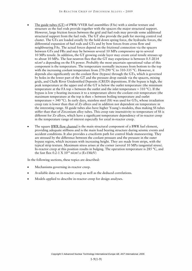
• The guide tubes (GT) of PWR/ VVER fuel assemblies (FAs) with a similar texture and structure as the fuel rods provide together with the spacers the major structural support. However, large friction forces between the grid and fuel rods may provide some additional structural support from the fuel rods. The GT also provide the path for moving control rod cluster. The GTs are loaded axially by the hold down spring force, the hydraulic forces, the differential expansion of fuel rods and GTs and by bow forces from cross flow and neighbouring FAs. The actual forces depend on the frictional connection via the spacers between GTs and FRs and may be between several 10 MPa compressive up to several 10 MPa tensile. In addition, the GT growing oxide layer may create axial tensile stresses up to about 10 MPa. The fast neutron flux that the GT may experience is between 0.5-2E14 n/cm2.s depending on the FA power. Probably the most uncertain operational value of this component is the temperature. The temperature normally increases from bottom to the top with the increasing coolant temperature from 270-290 °C to 310-335 °C. However, it depends also significantly on the coolant flow (bypass) through the GTs, which is governed by holes in the lower part of the GT and the pressure drop outside via the spacers, mixing grids, and Chalk River Unidentified Deposits (CRUD) depositions. If the bypass is high, the peak temperature at the upper end of the GT is below the outlet temperature (the minimum temperature at the FA top = between the outlet and the inlet temperature ≈ 310 °C). If the bypass is low γ-heating increases it to a temperature above the coolant exit temperature (the maximum temperature at the top is then = between boiling temperature and outlet temperature ≈ 340 °C). In early days, stainless steel (SS) was used for GTs, whose irradiation creep rate is lower than that of Zr-alloys and in addition not dependent on temperature in the interesting range. SS guide tubes also have higher Young’s modules, thus making SS tubes stiffer than that of Zirconium alloy tubes. This creep rate insensitivity to temperature of SS is different for Zr-alloys, which have a significant temperature dependency of in-reactor creep in the temperature range of interest especially for axial in-reactor creep.
• The square BWR flow channel is the main structural component of a BWR fuel element, providing adequate stiffness and is the main load bearing structure during seismic events and accident conditions. It also provides a cruciform path for control blade manoeuvring. They are stressed by the difference between the coolant pressure and the pressure in the outer bypass region, which increases with increasing height. They are made from strips, with the typical strip texture. Maximum stress arises at the corner (several 10 MPa tangential stress). In-reactor creep at this position results in bulging. The operation temperature is 285 °C, and the fast flux 0.2-1 X 10¹⁴ n/cm2.s (E>1MeV)
In the following sections, these topics are described:
• Mechanisms governing in-reactor creep.
• Available data on in-reactor creep as well as the deduced correlations.
• Models applied to describe in-reactor creep for design analyses.

I N - R E A C T O R C R E E P O F Z I R C O N I U M A L L O Y S – 2 0 0 9
2 Irradiation creep mechanisms (Ron Adamson)
2.1 Metallurgical background
2.1.1 Dislocations
When materials scientists first realized that metals consisted of a regular array of atoms arranged in planes, they were able to calculate the stress needed to cause one plane of atoms to move one atom position relative to the adjacent plane of atoms. The stress required was about 107 psi (69 000 MPa), which is at least 100X greater than observed experimentally. The concept of a lattice defect, the dislocation, was therefore introduced to explain the discrepancy. It was shown theoretically that a dislocation could move through the crystal lattice at far less than the theoretical stress, and that it would produce a slip step, or a shear step, at a free surface.
Although it is not important for the purposes of this Irradiation Creep Special Topic Report to examine dislocation theory, it will be helpful to review some basic geometries and terms. As indicated in (Figure 2-1), a dislocation can be envisioned as an extra plane of atoms in the lattice. Because the interatomic forces around the dislocation line are different than in a perfect lattice, the dislocation (in the illustrated case an edge dislocation) can move under the influence of an applied shear stress. When the edge dislocation reaches a free surface it does indeed cause a step at the surface. (Figure 2-2) illustrates the case of a dislocation, or group of dislocations, intersecting the surface of a copper single crystal. The basic phenomena are the same for Zircaloy.
Figure 2-1: The motion of an edge dislocation and the production of a unit step of slip at the surface of the crystal. (a) An edge dislocation in a crystal structure. (b) The dislocation has moved one lattice spacing under the action of a shearing force. (c) The dislocation has reached the edge of the crystal and produced unit slip, [Dieter 1961].
Copyright © Advanced Nuclear Technology International Europe AB, ANT International, 2009.
2-1(2-56)=
I N - R E A C T O R C R E E P O F Z I R C O N I U M A L L O Y S – 2 0 0 9
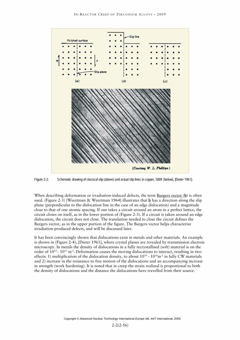
Figure 2-2: Schematic drawing of classical slip (above) and actual slip lines in copper, 500X (below), [Dieter 1961].
When describing deformation or irradiation-induced defects, the term Burgers vector (b) is often used. (Figure 2-3) [Weertman & Weertman 1964] illustrates that b has a direction along the slip plane (perpendicular to the dislocation line in the case of an edge dislocation) and a magnitude close to that of one atomic spacing. If one takes a circuit around an atom in a perfect lattice, the circuit closes on itself, as in the lower portion of (Figure 2-3). If a circuit is taken around an edge dislocation, the circuit does not close. The translation needed to close the circuit defines the Burgers vector, as in the upper portion of the figure. The Burgers vector helps characterize irradiation-produced defects, and will be discussed later.
It has been convincingly shown that dislocations exist in metals and other materials. An example is shown in (Figure 2-4), [Dieter 1961], where crystal planes are revealed by transmission electron microscopy. In metals the density of dislocations in a fully recrystallised (soft) material is on the order of 1012 - 1013 m-2. Deformation causes the moving dislocations to interact, resulting in two effects: 1) multiplication of the dislocation density, to about 1014 - 1016m-2 in fully CW materials and 2) increase in the resistance to free motion of the dislocations and an accompanying increase in strength (work hardening). It is noted that in creep the strain realized is proportional to both the density of dislocations and the distance the dislocations have travelled from their source.
Copyright © Advanced Nuclear Technology International Europe AB, ANT International, 2009.
2-2(2-56)=

I N - R E A C T O R C R E E P O F Z I R C O N I U M A L L O Y S – 2 0 0 9
Figure 2-3: Burgers circuit around edge dislocation. The Burgers vector is b, [Weertman & Weertman 1964].
Figure 2-4: Electron Micrograph of dislocation in a crystal of platinum phthalocyanine (X1,500000). (a) Example of perfect array of crystal planes. (b) Perfect array interrupted by a dislocation. (c) Schematic drawing of (b) showing position of the dislocation, [Dieter 1961].
2.1.2 Point defects
Another class of defects, which is important to the understanding of mechanical properties, is the PD. Some types are illustrated in (Figure 2-5), [Dowling 1999]. A substitutional impurity occupies a normal lattice site but is an atom of a different element than the bulk material. A vacancy is the absence of an atom at a normally occupied lattice site, and an interstitial is an atom occupying a position between normal lattice sites. If the interstitial is of the same type as the bulk material, it is called a Self Interstitial (SIA) and if it is of another kind it is called an impurity interstitial.
Figure 2-5: Four types of PDs, [Dowling 1999].
Copyright © Advanced Nuclear Technology International Europe AB, ANT International, 2009.
2-3(2-56)=
I N - R E A C T O R C R E E P O F Z I R C O N I U M A L L O Y S – 2 0 0 9
Relatively small impurity atoms often occupy interstitial sites in materials with larger atoms. In zirconium alloys common interstitials are O, H, C, Fe, Cr and Ni. Common substitutional impurities (or alloying elements) are Sn and Nb, which have significant influence on strength and creep.
It is seen in (Figure 2-1) that the region around an edge dislocation is under stress due to the disruption of the normal lattice spacing there. As a result, this region strongly interacts with the strain fields of the vacancies, interstitials and SIAs. For instance, for temperatures around 523 K (300 °C), oxygen in zirconium is strongly attracted to dislocations, and significantly affects the strength of unirradiated materials.
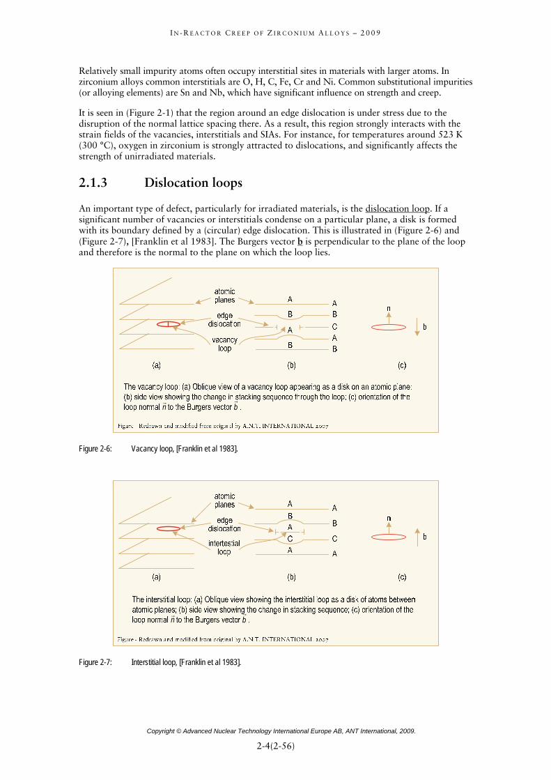
2.1.3 Dislocation loops
An important type of defect, particularly for irradiated materials, is the dislocation loop. If a significant number of vacancies or interstitials condense on a particular plane, a disk is formed with its boundary defined by a (circular) edge dislocation. This is illustrated in (Figure 2-6) and (Figure 2-7), [Franklin et al 1983]. The Burgers vector b is perpendicular to the plane of the loop and therefore is the normal to the plane on which the loop lies.
nr
br
Figure 2-6: Vacancy loop, [Franklin et al 1983].
nr
br
Figure 2-7: Interstitial loop, [Franklin et al 1983].
Copyright © Advanced Nuclear Technology International Europe AB, ANT International, 2009.
2-4(2-56)=
I N - R E A C T O R C R E E P O F Z I R C O N I U M A L L O Y S – 2 0 0 9
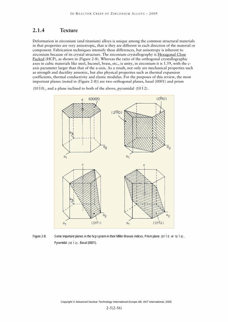
2.1.4 Texture
Deformation in zirconium (and titanium) alloys is unique among the common structural materials in that properties are very anisotropic, that is they are different in each direction of the material or component. Fabrication techniques intensify these differences, but anisotropy is inherent to zirconium because of its crystal structure. The zirconium crystallography is Hexagonal Close Packed (HCP), as shown in (Figure 2-8). Whereas the ratio of the orthogonal crystallographic axes in cubic materials like steel, Inconel, brass, etc., is unity, in zirconium it is 1.59, with the c-axis parameter larger than that of the a-axis. As a result, not only are mechanical properties such as strength and ductility anisotric, but also physical properties such as thermal expansion coefficients, thermal conductivity and elastic modulus. For the purposes of this review, the most important planes (noted in (Figure 2-8)) are two orthogonal planes, basal (0001) and prism
, and a plane inclined to both of the above, pyramidal . )0110(−
)2110(−
Figure 2-8: Some important planes in the hcp system in their Miller-Bravais indices. Prism plane or .
Pyramidal . Basal (0001).
0101−
( )0110−
)( 2110−
Copyright © Advanced Nuclear Technology International Europe AB, ANT International, 2009.
2-5(2-56)=

I N - R E A C T O R C R E E P O F Z I R C O N I U M A L L O Y S – 2 0 0 9
To enable the degree of anisotropy to be predicted, the texture (e.g., arrangement of crystallographic planes) of a specimen or component is usually expressed as an average distribution of basal (0001) planes in a particular direction of interest. X-ray diffraction techniques are used to obtain this distribution or the distribution of any plane of interest, [Lewis et al 1982]. (Figure 2-9) [Schemel 1989] shows the distribution of basal poles (normal to the basal plane) in various circumstances, with the usual distribution in Zircaloy tubing shown in (Figure 2-9e). More quantitatively, the distribution of basal poles is expressed by the Kearns texture parameter, fx, where fx is the resolved volume fraction of basal poles lying in the x-direction. The following definitions apply:
fl = longitudinal (rolling, axial) direction
ft = transverse (circumferential) direction
fn = normal (radial) direction
fl + ft + fn = 1
f = 0.33 implies randomly oriented basal poles
In (Figure 2-9b), fl = fn = 0 and ft = 1
In (Figure 2-9d), fl = ft = 0 and fn = 1
In (Figure 2-9c), fl = fn = ft = .33
In (Figure 2-9e), showing a typical texture in Zircaloy tubing, fl = 0.07, ft = 0.33, fn = 0.60
In a typical rolled plate fl = .1, ft = .3, fn = .6
A detailed account of texture-related deformation in zirconium alloys is given by [Tenckhoff 1988], a summary of which is given in [Rudling & Adamson 2000].
Figure 2-9: Illustration of crystal textures in tubing, [Schemel 1989].
Copyright © Advanced Nuclear Technology International Europe AB, ANT International, 2009.
2-6(2-56)=
I N - R E A C T O R C R E E P O F Z I R C O N I U M A L L O Y S – 2 0 0 9
2.1.5 Irradiation damage
2.1.5.1 General
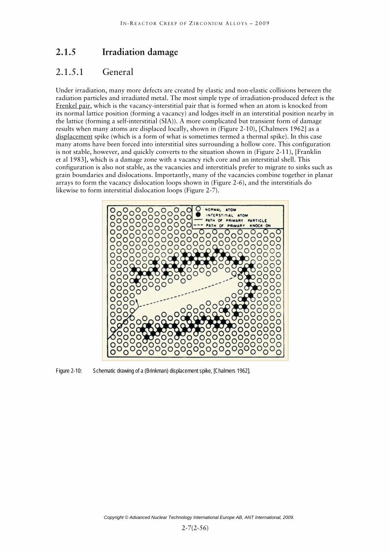
Under irradiation, many more defects are created by elastic and non-elastic collisions between the radiation particles and irradiated metal. The most simple type of irradiation-produced defect is the Frenkel pair, which is the vacancy-interstitial pair that is formed when an atom is knocked from its normal lattice position (forming a vacancy) and lodges itself in an interstitial position nearby in the lattice (forming a self-interstitial (SIA)). A more complicated but transient form of damage results when many atoms are displaced locally, shown in (Figure 2-10), [Chalmers 1962] as a displacement spike (which is a form of what is sometimes termed a thermal spike). In this case many atoms have been forced into interstitial sites surrounding a hollow core. This configuration is not stable, however, and quickly converts to the situation shown in (Figure 2-11), [Franklin et al 1983], which is a damage zone with a vacancy rich core and an interstitial shell. This configuration is also not stable, as the vacancies and interstitials prefer to migrate to sinks such as grain boundaries and dislocations. Importantly, many of the vacancies combine together in planar arrays to form the vacancy dislocation loops shown in (Figure 2-6), and the interstitials do likewise to form interstitial dislocation loops (Figure 2-7).
Figure 2-10: Schematic drawing of a (Brinkman) displacement spike, [Chalmers 1962].
Copyright © Advanced Nuclear Technology International Europe AB, ANT International, 2009.
2-7(2-56)=

I N - R E A C T O R C R E E P O F Z I R C O N I U M A L L O Y S – 2 0 0 9
Figure 2-11: Illustration of a damage zone with a vacancy rich core and an interstitial (SIA) shell, [Franklin et al 1983].
In a reactor environment, defects are potentially produced by neutrons, beta particles (electrons), alpha particles and gamma rays (γ-rays). The types of defects produced by each is illustrated in (Figure 2-12), [Van Bueren 1961]. Neutrons and alpha particles cause the most damage per particle, but because of its electrical charge alphas have a very short range in metals. Electrons and gammas have a large range in metals, but cause very few defects, mainly isolated Frenkel pairs.
Copyright © Advanced Nuclear Technology International Europe AB, ANT International, 2009.
2-8(2-56)=

I N - R E A C T O R C R E E P O F Z I R C O N I U M A L L O Y S – 2 0 0 9
Figure 2-12: Irradiation damage caused by various particles in metals, [Van Bueren 1961].
2.1.5.2 Zirconium alloys
In structural materials like Zircaloy, the overwhelming majority of defects are caused by neutrons, and the most important type of defect is the dislocation loop. Two types of loops predominate: <a> and <c> loops. The <a> loop lies on a prism plane and has a Burgers vector in the <a>-direction of the HCP lattice, see (Figure 2-6), (Figure 2-7) and, (Figure 2-8). (Table 2-1) lists some important characteristics. Both vacancy and interstitial loops exist, but more than half have vacancy character. They are very small (20 nm) “black spots”) and even in the Transmission Electron Microscope (TEM) are difficult to analyze (Figure 2-13a) and (Figure 2-13b).
<a> loops form early in the irradiation and the number density reaches a saturation value at a fuel burnup less than 5 GWd/MT. The size of the loops increases with irradiation temperature, and the loops become unstable (start to disappear) at about 673 K (400 °C). As will be discussed later they have a strong effect on mechanical properties.
Copyright © Advanced Nuclear Technology International Europe AB, ANT International, 2009.
2-9(2-56)=

I N - R E A C T O R C R E E P O F Z I R C O N I U M A L L O Y S – 2 0 0 9
Table 2-1: Radiation Damage, <a> loops in Zircaloy.
Nature vacancy(+), interstitial
Size 8 –20 nm (80-100 Å)
Density 8 X 10¹⁴ m-2
Saturation Fluence 1 X 1025 n m-2 (E>1 MeV)
Thermal stability to about 400 °C (673 K)
Effect strength, ductility, growth, creep
Figure 2-13a: <a> type dislocation loops in Zircaloy-2 neutron irradiated at about 300 °C (573 K) (after post-irradiation annealing at 723 K for 1 hour), [Adamson 2000].
Figure 2-13b: <a> type dislocation loops in Zircaloy-2 neutron irradiated at 300 °C (573 K), [Holt 2007].
Copyright © Advanced Nuclear Technology International Europe AB, ANT International, 2009.
2-10(2-56)=

I N - R E A C T O R C R E E P O F Z I R C O N I U M A L L O Y S – 2 0 0 9
The <c> type of loop lies on the basal plane and has its Burgers vector, or at least a strong component of it, in the c-direction of the HCP cell. As indicated in (Table 2-2), unlike the <a> loop, it is strictly a vacancy-type loop, is relatively large (>100 nm) and does not form until considerable irradiation effects have accumulated. In Zircaloy <c> loops are first observed by TEM at a burnup of around 15 GWd/MT (7 X 1025 n/m2, E>1MeV) and increase in density the rest of the fuel lifetime. They are thermally stable to high temperature >560 °C (>833 K). <c> loops are thought to strongly influence irradiation growth and creep behaviour, and probably do not affect mechanical properties. (Figure 2-14a) and (Figure 2-14b) shows TEM images of a high density of <c> loops in highly irradiated Zircaloy. Appearance of <c> loops is delayed in fluence in some zirconium alloys, particularly in those having additions of Nb or Nb and Fe.
Table 2-2: Radiation Damage, <c> loops in Zircaloy.
Nature vacancy
Size > 100 nm (1000 Å)
Density 0.5 X 10¹⁴ m-2 (For Figure 2-14a)
Incubation Fluence 3 X 1025 n m-2 (E>1 MeV)
Thermal stable to >560 °C (833 K) form at >200 °C (475 K)
Effect growth, creep, ?
Figure 2-14a: <c> type dislocations in Zircaloy-4 after a fluence of 12 x 1021 n/m2 at 288 °C (561 K), [Adamson 2000].
Copyright © Advanced Nuclear Technology International Europe AB, ANT International, 2009.
2-11(2-56)=
I N - R E A C T O R C R E E P O F Z I R C O N I U M A L L O Y S – 2 0 0 9
3 Available data on in-reactor creep and deduced correlations (Friedrich Garzarolli)
3.1 Available data on in-reactor creep and principle analysis approach
Results from several large programs on in-reactor creep were reported in the past 40 years. The data from the following programs were used for the data analysis performed for this report.
• Bettis [Kreyns & Burkart 1968] reported on in-reactor stress relaxation tests on several Zr alloys at high fast neutron fluxes.
• The largest program on in-reactor creep was performed by Atomic Energy of Canada Limited (AECL) in test reactors and CANDU reactors. They examined CANDU pressure tubes especially extruded + CW + SR Zry-2 and β(α+β)-quenched + extruded + CW + aged Zr2.5Nb. It should be mentioned that the creep strength of this Zr2.5Nb material is significantly higher than that of Zr2.5Nb used for fuel rods (which have seen after extrusion several rocking and annealing steps), at least at temperatures between 270 and 310 °C. This is mainly due to different textures developed by the different fabrication schedules. Uniaxial stress relaxation tests, uniaxial creep tests, and pressurised tube creep tests have been performed especially with CW Zry-2 and Zr2.5Nb mostly at rather moderate fluxes, e.g. [Fidleris 1968], [Fidleris 1970], [Ross-Ross et al 1972], [Ross-Ross & Hunt 1968], [Ibrahim 1969], [Ibrahim 1973], [Ibrahim 1974], [Holt 1979], [Holt et al 2003], [Holt et al 2008], [Causey 1974a], [Causey 1974b], [Causey 1981], [Causey et al 1980], [Causey et al 1994] and [Causey et al 2000].
• [Kohn 1977] reported on in-reactor creep of Zr2.5Nb fuel cladding operating in the reactor Water Rod (WR-1) with an organic coolant at temperatures up to 480 °C. The data are interesting especially for the creep rate temperature dependency, but it can be questioned, whether the neutron energy spectrum is comparable to that of CANDU or LWRs.
• United Kingdom Atomic Energy Authority (UKAEA) studied the in-reactor creep behaviour of Zry-2 and Zr2.5Nb especially at high stresses in test reactors, [Watkins & Wood 1969], [Wood & Watkins 1971] and [Wood 1974].
• [Harbottle & Cornell 1979] reported on the analysis of fuel rod diameter and length changes of different Zry-2 cladding materials after irradiation in BR3.
• At Batelle uniaxial creep tests [Gilbert 1968], [Gilbert & Harding 1969] and [Gilbert & Mastel 1969] were performed especially with Zry-2 and Zr2.5Nb and moderate fluxes. The information on fast flux for these experiments is, however, scarce.
• Electric Power Research Institute (EPRI) [Franklin et al 1983], [Papazoglou & Davis 1983] and [Baty et al 1984] performed programs on the creep behaviour of fuel rod claddings in commercial PWRs jointly with Babcock & Willcox (B&W) and Combustion Engineering (CE).
• [Tinti 1983] reported on uniaxial in-reactor creep tests of CW Zry-2 performed in the Siloe reactor. The dimensional changes were measured relative to an adjacent unstressed specimen eliminating thereby any contribution from irradiation growth.
• CEA studied irradiation creep of Zry-4 under internal pressure and axial stress in the Siloe reactor [Frenkel & Weisz 1973], [Morize 1976], [Yvon et al 1999], [Gilbon et al 2000] and [Soniak et al 2002]. Some tests were also done with M5, M4 and a ZrNbSnFe alloy.
Copyright © Advanced Nuclear Technology International Europe AB, ANT International, 2009.
3-1(3-47)=

I N - R E A C T O R C R E E P O F Z I R C O N I U M A L L O Y S – 2 0 0 9
• Siemens tested tubular samples of different Zry-4 lots with varying differential pressures (between inside and outside of the tube sample) in a commercial PWR for 1 to 5 cycles, [Garzarolli et al 1996]. In addition several Zry-4 type variants and alternative Zr-alloys were tested under compressive tangential or axial stresses. Some data are published by [Seibold et al 2000] and [Hoffmann & Dewes 2001]. In addition creep tests were performed in the FRG-2 at GKSS, [Böhner et al 1987]. Furthermore in-reactor creep of several alternative Zr alloy claddings were studied by irradiation of experimental fuel rods in KKGg, [Seibold & Garzarolli 2002].
• The Japanese studied in-reactor creep of ZIRLO and Mitsubishi Developed Alloy (MDA) claddings during irradiation in Vandellos 2, [Kido et al 2002].
• Irradiation of internally pressurised tubular ZIRLO creep samples with different material conditions in the Vogtle Unit 2 PWR were reported by Westinghouse, [Foster et al 2007].
• In Halden the effect of preirradiation and stress changes on in-reactor creep was studied for RX Zry-2, SR-Zry-4, SR ZIRLO, and RX M5 and E110 [McGrath et al 2000], [McGrath & Bennett 2002], [McGrath 2005] and [Foster & McGrath 2007].
• Irradiation creep tests with internally pressurised tubular samples of E110, E635 and different Zr-Nb-Sn-Fe alloys were performed by the Russians in the BOR 60 and BRT-6 reactors, e.g. [Shishov et al 2007] and [Rogozyanov et al 2001].
• Studies using an ion accelerator to simulate very high fluxes were published by [Chapman et al 1984].
The individual creep test result data from relaxation tests, uniaxial creep tests, creep tests of pressurised tubular samples, and of PWR fuel rods are listed in Appendix A to Appendix D, including the available information on material chemistry and condition. In cases, were important material information were not given, these values were estimated by the author. The estimated values are given in violet with bold gothic letters. Some data (e.g. the Yield Strength) were reported for another temperature and were therefore converted to 300 °C. In some cases the creep values were re-evaluated from the data given in the original reports. In-reactor creep results from accelerator experiments, used for this data analysis, are listed in Appendix E.
Most in-reactor creep models assume that long-term, steady-state plastic deformation consists of separable, additive components from thermal creep, irradiation creep and irradiation growth. The thermal creep contribution in-reactor is that of an irradiated material and may differ from the creep behaviour of unirradiated material tested out of flux. At temperatures below 350 °C the contribution from thermal creep is small, at least at the moderate stresses of interest for long time behaviour of fuel components and pressure tubes. For the analysis of the in-rector creep data in the temperature range of 275-390 °C in this report no differentiation was done between thermal and irradiation creep. Thus the available data base was evaluated for in-reactor creep containing the combined effect of irradiation and thermal creep.
The time (t) dependency of creep deformation at stresses below yield stress (ε) is usually described by a primary strain (ε0) and a steady state creep rate (dε/dtirr):
(Eq. 3-1) tdtd irr ⋅+= /0 εεε
The other concept to describe the time dependency of creep deformation is a power law:
(Eq. 3-2) or kt≈ε kt)(ϕε ≈
Copyright © Advanced Nuclear Technology International Europe AB, ANT International, 2009.
3-2(3-47)=

I N - R E A C T O R C R E E P O F Z I R C O N I U M A L L O Y S – 2 0 0 9
The time or fast flux exponent k can be between 0.3 and 1 depending on the same factors that affect primary creep. In experiments where no primary creep is observed k is close to 1. The two different ways of analysis are shown in (Figure 3-1). Although there are good arguments to apply a power relationship, at least for the thermal creep component, practical aspects of an easier analysis and modelling have led to an exceptional use of the primary plus secondary creep concept (Eq. 3-1) in this report. A re-evaluation of the data was performed shown in Appendix B and Appendix C, if the data were reported as a power law (Eq. 3-2).
Figure 3-1: Graph showing the two different methods to analyze in-reactor creep, [Wood 1975].
The measured dimensional change during irradiation is the sum of irradiation growth and creep. The growth contribution depends on the material texture, is largest in the axial direction and smallest in the tangential direction. Thus, the growth contribution in the axial direction can affect the total length change rate significantly at low stress levels, as shown in (Figure 3-2). For this reported review the creep data used do not contain any contribution of irradiation growth, although the applied correction for the irradiation growth contribution was only roughly estimated.
Copyright © Advanced Nuclear Technology International Europe AB, ANT International, 2009.
3-3(3-47)=

I N - R E A C T O R C R E E P O F Z I R C O N I U M A L L O Y S – 2 0 0 9
4 Creep models (Charles Patterson)
4.1 Introduction
Previous sections identified the range of physical processes that affect creep of zirconium alloys. Previous sections also addressed the effects of material chemistry, texture and microstructural conditions on the creep processes. In addition, they identified the form of some of the relationshipused to describe the effects of variables such as stress, temperature, time, fast neutron flux and fluence on creep. Section
s
to identify how this information is applied in the solution of engineering problems.
begins by coa se atio re nd u l lo amples of creep models either in curren r t av o e pr he mu isotroformulations, which we d in Section re e o condi ariable,m adi he s tion wi rief d ion of h models applied in the anal mpl -core structures.
It should be noted hat Se n m ls suit r engineering nalyses of in-r ctor creep. The formulation of hese m tends em phenom al. Terms in the equations can be developed from available or ac tsuitable for rapid evaluation in the ment d, fr v straterequired for in-core cond ns. , Se 4 ig n important branch of modelling that addresses the mechanistic aspec creep and seeks to describe the effec creep in terms of the governing mechanis s; e.g., ELFP -N model for creep a tion g[Turner et al 199 Altho h s ha een us he analysis of zirconium alloystructures such as pressur ube U r ors, the basic physical pa meters necessa for reliable deformati pred ions wn hat th rical and ph menological models of this section still constitute the primary mea f engineering analysis, [Holt 2008].
The discussion of engineering application centers on the finite element method. This discussion is not intended to be a treatise on finite element modelling r, it seeks to identify how creep is addressed in what is now a primar l for a sis of plex stru and comploading typical of water cooled reacto of this discussion is to bridge the gap that sometimes exists between experimentalists, theoreticians and engineers with respect to creep and its role in the in-core performance of zirconium-based alloys.
4 attempts to expand on the modelling aspect of the previous sections and
Section 4 nsolidating the creep relationships presented in prior sections and presenting t of equ ns for c
t use oep uhat hre presente
er uniform,e been prop
niaxiased ar
3, a
ading. Exesented. Txtended t
that are pic non-
ltiaxial, antions of v
onotonic lo ng. T ec concludes th a b escript ow creep are ysis of co ex fuel and other in
t ction 4 focuses o ode able fo a eat odels to be pirical or enologic
hievablal an
e experimental data. Their strucequently, iterati
ure is gies incre e solution
itio As a result ction nores ats of
the Sts of
nd irradiam OLY rowth, 9]. ug uch models ve b ed in t
e tict
s in CAND are unkno
eact so t
raeno
ryon e empi
ns o
. Rathey too
rs. The objective naly the com ctures lex
Copyright © Advanced Nuclear Technology International Europe AB, ANT International, 2009.
4-1(4-38)=

I N - R E A C T O R C R E E P O F Z I R C O N I U M A L L O Y S – 2 0 0 9
4.2 Creep models for continuous, uniform loading
m alloys during irradiation can be treated as a collection of mation of time-independent (instantaneous) elastic and
plastic processes combined with terms involving thermal strain, irradiation growth and creep that
of creep models in this section. Consequently, the total strain at any point in time is given by the summation of
The stress-strain behaviour of zirconiurate (time) based processes or as a sum
vary with loading, time or both loading and time. Although the rate-based approach is being applied more frequently in the analysis of in-core components5 and offers the advantage of integrating the microstructural effects of plastic loading with those of creep and irradiation damage, the most common method continues to be the mixed formulation consisting of instantaneous elasticity and plasticity combined with terms addressing thermal expansion, irradiation growth and creep. This later formulation is assumed in the application
strains due to a set of physical processes which are assumed to act independently; i.e.,
(Eq. 4-1) crirthep εεεεε +++=
where =epε Elastic or elastoplastic strain depending on the state of loading,
=thε Thermal strain,
=irε Strain due to irradiation growth
and =crε Creep strain.
As noted in prior sections, creep can be further divided into thermal and irradiation components so that the total creep strain is given by:
(Eq. 4-2) ircr
thcrcr εεε +=
In-core applications typically involve variations of the applied forces, imposed displacements, temperature and neutron flux throughout the operating life. The material constitutive relationships also tend to be highly nonlinear. Consequently, mechanical models are generally structured for solution on an incremental basis so that:
(Eq. 4-3) ( )[ ]∑ Δ++Δ+Δ+Δ= tthcr
thcrirthep εεεεεε &&
dtdεε ≡& with
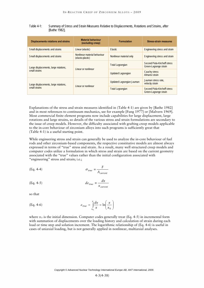
The small-strain (or Cauchy infinitesimal strain) theory is typically applicable to fuel and other in-core structures. Irradiation creep is rarely able to produce significant strains over the life of a FA. In addition, strains are limited to 1% by licensing regulations in some countries or by functional (fit-up) requirements, so the complexities associated with finite displacements and rotations can be ignored in the analysis of most operating conditions. For reference, however, a summary of the stress and strain formulations applicable to a wider range of conditions is given in (Table 4-1), as exceptions to small-strain theory exist within the full range of fuel rod conditions; e.g., cladding creep down into fuel column gaps or cladding ballooning under postulated LOCA conditions.
5 See for example [Delobelle et al 1996], [Richard et al 2003] and [Chaboche 2008].
Copyright © Advanced Nuclear Technology International Europe AB, ANT International, 2009.
4-2(4-38)=
I N - R E A C T O R C R E E P O F Z I R C O N I U M A L L O Y S – 2 0 0 9
Table 4-1: Summary of Stress and Strain Measures Relative to Displacements, Rotations and Strains, aft[Bathe 1982].
er
Displacements rotations and strains Material behaviour (excluding creep) Formulation Stress-strain measures
Small displacements and strains Linear (elastic) Elastic Engineering stress and strain
Small displacements and strains Nonlinear material behaviour (elasto-plastic) Nonlinear material only Engineering stress and strain
Large displacements, large rotations, small strains Linear or nonlinear
Total Lagrangian Second Piola-Kirchoff stress Green-Lagrange strain
Updated Lagrangian Cauchy stress Almansi strain
Jauman stress rate, Updated Lagrangian Jauman velocity strain Large displacements, large rotations, small strains Linear or nonlinear
Total Lagrangian Second Piola-Kirchoff stress Green-Lagrange strain
E the stress and strain measures idena rences to continuum mechanics, se
xplanations of tified in (Table 4-1) are given by [Bathe 1982] nd in most refe e for example [Fung 1977] or [Malvern 1969].
commercial finite element programs now include capabilities for large displacement, large ns and large s tails of the various stress and strain formulations are secondary to
ineering stress and strain can generally be used to analyze the in-core behaviour of fuel ys
nd t geometry
(Eq. 4-4)
Mostrotatio trains, so dethe issue of creep models. However, the difficulty associated with grafting creep models applicableto the in-core behaviour of zirconium alloys into such programs is sufficiently great that (Table 4-1) is a useful starting point.
While engrods and other zirconium-based components, the respective constitutive models are almost alwaexpressed in terms of “true” stress and strain. As a result, many well structured creep models acomputer codes utilize a formulation in which stress and strain are based on the currenassociated with the “true” values rather than the initial configuration associated with “engineering” stress and strain; i.e.;
currenttrue A
≡σ F
(Eq. 4-5) currentx
so that
(Eq. 4-6)
truedx
d ≡ε
∫ ⎟⎟⎠
⎞⎜⎜⎝
⎛==
x
xtrue x
xx
dx
0 0
lnε
where x0 is the initial dimension. Computer codes generally treat (Eq. 4-5) in incremental form with summation of displacements over the loading history and calculation of strain during each load or time step and solution increment. The logarithmic relationship of (Eq. 4-6) is useful in cases of uniaxial loading, but is not generally applied in nonlinear, multiaxial analyses.
Copyright © Advanced Nuclear Technology International Europe AB, ANT International, 2009.
4-3(4-38)=

I N - R E A C T O R C R E E P O F Z I R C O N I U M A L L O Y S – 2 0 0 9
5 References
Adamson R. B., “Irradiation Growth of Zircaloy”, Zirconium in the Nuclear Industry; Third Conference, ASTM STP 633, pp. 326, 1977.
Adamson R. B. and Bell W. L., “Effects of Neutron Irradiation and Oxygen Content on the ucture and Mechanical Properties of Zircaloy Microstructure and Mechanical
Behavior of Materials, Proceedings: Int’l Symposiums, Xian, China, Oct. 1985, EMAS, arley, UK, 237-246, 1986.
B., Wisner, S. B., Tucker, R. P. and Rand. R. A., “Failure Str in for Irradiated Based on Subsized Specimen Testing and Analysis”, The Use of Small-Scale
Microstr ”,
W
Adamson R. aZircaloySpecimens for Testing Irradiated Material, ASTM STP 888, W. R. Corwin and G. E. Lucas, Eds., American Society for Testing and Materials, Philadelphia, 171-185, 1986.
d
e
nd
-uclear Materials,
Vol. 30, pp. 208-218, 1969.
Bathe K. J., Finite Element Procedures in Engineering Analysis
Adamson R. B., “Effects of Neutron Irradiation on Microstructure and Properties of Zircaloy”, Zirconium in the Nuclear Industry; Twelfth International Symposium, ASTM STP 1354, pp. 15-31, West Conshohocken, PA, 2000.
Adamson R. B. and Rudling P., “Dimension Stability of Zirconium Alloys”, Special Topics Report, ANT International, Skultuna, Sweden, ANT International, 2002/2003.
Adamson R. B., “Recovery of Irradiation Damage by Posts-Irradiation Thermal Annealing-Relevance to Hydrogen Solubility and Dry Storage Issues, “EPRI Technical Report 1013446, June 2006.
Alexander W. K., Fidleris V. and Holt R. A., “Zry-2 pressure tube elongation at the Hanford N Reactor”, ASTM Spec. Techn. Publ. 633), pp. 344-364, 1977.
Anand M. S., Mansel W., Wallner G. and Weck W., “Effect of alloying elements on recovery andamage rates in zirconium”, J. Nucl. Mater. Vol. 126, pp. 144-151, 1984.
Andrews M. G., Freeburn H. R. and Pati S. R., “Light Water Reactor Fuel Rod Modeling CodEvaluation, Phase II, Topical Report”, Combustion Engineering Report CENPD-218, DOE Contract EN-76-C-02-2426, 1976.
Ardell A. J., “On the calculation of melting temperatures of low temperature phases of polymorphic metals”, Vol.11, issue 6, p. 591, 1963.
Ashby M. F. and Jones R. H., Engineering Materials 1, 2 Edition, Butterworth-Heinemann, Boston, 2001.
Azzarto F. J., Baldwin E. E., Wiesinger F. W. and Lewis D. M., “Unirradiated, In-Pile and PostIrradiation Low Strain Rate Tensile Properties of Zircaloy-4”, Journal of N
, Prentice-Hall, Englewood Cliffs, New Jersey, 1982.
Baty D. L. et al., “Deformation characteristics of cold-worked and recrystallised Zey-4 cladding”, ASTM STP 842, pp. 306-339, 1984.
Bell W. L., Zirconium In Nuclear Applications, ASTM STP 551, ASTM, 199-200, 1974.
Berna G. A., Beyer C. E., Davis K. L. and Lanning D. D., “FRAPCON-3: A Computer Code for the Calculation of Steady-State, Thermal-Mechanical Behavior of Oxide Fuel Rods for High Burnup”, NUREG/CR-6534 Vol. 2, PNNL-1153, 1997.
Copyright © Advanced Nuclear Technology International Europe AB, ANT International, 2009.
5-1(5-12)=
I N - R E A C T O R C R E E P O F Z I R C O N I U M A L L O Y S – 2 0 0 9
Bok . B., ii G Crystal Chemistry, Moscow, 1960.
Bouffioux P. and Rupa N., “Impact of Hydrogen on Plasticity and Creep of Unirradiated Zry-4
., American Society for Testing and Materials, pp. 399-422, West Conshohocken, PA, 2000.
Bu
Bullough R. and Hayns M. ”, J. Nucl.
Bu
Bö Nb3Sn1
Cause Alloys”, ASTM STP 551, pp. 263-272, 1974a.
68 K 1974b.
Ca Schulte C. W., “In-reactor deformation of Zr2.5Nb
Ca n the Anisotropy of in-reactor creep of
Ca R. A., Christodoulou N. and Ho E. T. C., “Irradiation-enhanced deformation of
Ch Plasticity and Viscoplasticity Constitutive Theories, Int. J. Plasticity,
Ch etallurgy, John Wiley & Sons, Inc. 1962.
08.
g
Ch ontent on the Thermal Creep of Zirconium Alloy Tubes at 400° C”, Journal of Nuclear Materials, 255, pp. 78-82, 1998.
Cladding Tubes”, Zirconium in the Nuclear Industry: Twelfth International Symposium, ASTM STP 1354, Sabol G. and Moan G., Eds
ckley S. N., “Properties of reactor Materials and the Effects of Irradiation Damage”, Butterworths, London, p. 443, 1961.
R. ”Irradiation Creep due to Point Defect AbsorptionMater. 57, pp.348 -352, 1975.
llough R. and Wood M. H., J. Nucl. Mater.90, p.1, 1980.
hner G., Wildhagen B. and Wilhelm H., “In-pile creep behaviour of Zry-4 and Zrcladding under uniaxial and biaxial stress”, 9th Intern. Conf. On Structural Mechanics Technology (SMIRT 9), Lusanne, Switzerland, August 17-21.1987.
y A. R., “In-Reactor Stress Relaxation of Zr
Causey A. R., “In reactor creep of Zircaloy-2, Zircaloy-4 and Zr-l.15 wt% Cr- 1 wt%Fe at 5derived from their stress relaxation behaviour”, J. Nucl. Mat. Vol. 54, pp.64-72,
Causey A. R., Thermally Induced Strain Recovery In Irradiated and Unirradiated Zirconium Alloy Stress-Relaxation Specimens”, Journal of Nuclear Materials 6, pp. 71-78, 1976.
Causey A. R., Carpenter G. J. C. and MacEwen S. R., “In Reactor Stress Relaxation of Selected Metals and Alloys at Low Temperature”, J. Nucl. Mater. 90, pp. 216-223, 1980.
Causey A. R., “Anisotropy of irradiation creep of Zr2.5wt%Nb and Zircaloy-2 alloys”, J. Nucl. Mat. Vol. 98, pp.313-321, 1981.
Causey A. R., Holt R. A. and MacEwen S. R., “In-reactor creep of Zr2.5Nb”, ASTM Spec. Techn. Publ. 824, pp. 269-, 1984.
usey A. R., Fidleris V., MacEwen S. R. and pressure tubes”, ASTM Spec. Techn. Publ. 956, pp. 54-, 1988.
usey A. R., Elder J. E., Holt R. A. and Fleck R. G., “OZr-2.5Nb tubes”, ASTM STP 1245, pp. 202-220, 1994.
usey A. R., HoltZr-2.5Nb tubes at high neutron fluences”, Zirconium in the Nuclear Industry: Twelfth International Symposium, ASTM STP 1354, pp. 74-85, ASTM, West Conshohocken, PA, 2000.
aboche J. L., A Review of SomeVol. 24, pp. 1642 – 1693, 2008.
almers B., Physical M
Chang K. I. and Hong S. I., “Effect of Sulfur on the Strengthening of a Zr-Nb Alloy”, Journal of Nuclear Materials, 373, pp. 16-21, 20
Chapman O. J. V., McElroy R. J. and Sheldon E. E., “Irradiation Creep and Growth durinProton and Neutron Bombardment of Zircaloy Plate”, Zirconium in the Nuclear Industry, Sixth International Symposium, ASTM STP 824, pp. 363-375, 1984.
arquet, D., Senevat, J., Mardon, J., “Influence of Sulfur C
Copyright © Advanced Nuclear Technology International Europe AB, ANT International, 2009.
5-2(5-12)=

I N - R E A C T O R C R E E P O F Z I R C O N I U M A L L O Y S – 2 0 0 9
Charquet D., “Microstructure and properties of Zr alloys in absence of irradiation”, ASTM STP-1354, pp. 3-14, 2000.
Ch nal
Cheadle B. A., Ells C. E. and van der Kuur, J., “Plastic Instability in Irradiated Zr-Sn and Zr-Nb esting
of atmospheres”, Nuclear Technology Vol. 85, p.57, 1989.
radiation Growth of Zirconium Single Crystals”, J. Nucl. Mat., in press, 2009.
Ch and tubes in CANDU power
reactors”, Zirconium in the Nuclear Industry: Eleventh International Symposium, ASTM
Ch4.4 MeV protons at 347K”, J. Nucl. Mater, Vol. 328, pp. 1-10, 2004.
Co 1975.
Nuclear Industry: Tenth International Symposium, ASTM STP 1245, A. M. Garde and E. R. Bradley,
Dieter G. E., “Mechanical Metallurgy”, McGraw-Hill Book Company, Inc., 1961.
Do adiation Effects, Vol. 16,
Do reep in Zirconium-based Alloys”, iety for Testing and
Dozirconium”, Phil. Mag., 85, pp. 569-575, 2005.
Do iour of Materials, 2nd Edition”, Prentice Hall,
Ferrer F., Barbu A., Bretheau T., Crépin J., Willaime F. and Charquet D. L, “The Effect of Small
th International Symposium, ASTM STP 1423, G. D. .
Fid
ctor creep of heat treated Zr2.5Nb and cold worked
arquet D., “Phase constitution and steam corrosion resistance of binary Zr–S alloys”, Jourof Nuclear Materials, Volume 304, Issues 2-3, pp. 246-248, August 2002.
Alloys”, Zirconium in Nuclear Applications, ASTM STP 551, American Society for Tand Materials, 370-384, 1974.
Chin B. A. and Gilbert R. E., “Prediction of Maximum allowable temperature for dry storageZircaloy-clad spent fuel in inert
Christien F. and Barbu A., “Cluster Dynamics Modelling of Ir
ristodoulou N. Causey A. R., Holt R. A., Tomé C. N., Badie N., Klassen R. J., Sauvé R. Woo C. H., “Modeling in-reactor deformation of Zr-2.5Nb pressure
1295, E.R. Bradely and G. P. Sabol, Eds. American Society for Testing and Materials, pp. 518-537, 1996.
ow C. K., Holt R. A., Woo C. H. and So C. B., “Deformation of zirconium irradiated by
leman C. E. et al., “Uniaxial in reactor creep of Zr2.5Nb at 570 K”, AECL Report 5042,
Davies P. H., Hosbons R. R., Griffiths M. and Chow C. K., “Correlation Between Irradiated and Unirradiated Fracture Toughness of Zr-2.5Nb Pressure Tubes”, Zirconium in the
Eds., American Society for Testing and Materials, Philadelphia, 135-167, 1994.
Delobelle P., Robinet P., Geyer P. and Bouiffioux P., “A Model to Describe the Anisotropic Behavior of Zircaloy-4 Tubes”, J. Nuclear Materials, Vol. 238, pp. 135 – 162, 1996.
llins C. C., “Post irradiation recovery of irradiation damage”, Rpp. 271-280, 1972.
llins C. C. and Nichols F. A., “Mechanism of Irradiation CZirconium in Nuclear Applications, ASTM STP 551, American SocMaterials, pp. 229-247, 1974.
main C. and Legris A., “Ab initio atomic-scale determination of point-defect structure in hcp
wling N. E., “Mechanical BehavISBN-0-13-905720-X, 1999.
Concentration of Sulfur on the Plasticity of Zirconium Alloys at Intermediate Temperatures”, Zirconium in the Nuclear Industry: ThirteenMoan and P. Rudling, Eds., ASTM International, pp. 863-887, West Conshohocken, PA, 2002
leris V., “Uniaxial in-reactor creep of zirconium alloys”, J. Nucl. Mater. 26, pp. 51-76, 1968.
Fidleris V., “Stress dependence of in-reaZircaloy-2”, J. Nucl. Mat. Vol. 36, p. 343, 1970.
Copyright © Advanced Nuclear Technology International Europe AB, ANT International, 2009.
5-3(5-12)=