In-Plane Elastic Stability of Arches under a Radial ...file.scirp.org/pdf/ENG_2014081414542343.pdfIn...
13
Engineering, 2014, 6, 572-583 Published Online August 2014 in SciRes. http://www.scirp.org/journal/eng http://dx.doi.org/10.4236/eng.2014.69058 How to cite this paper: Xu, Y.J., Gui, X.M., Zhao, B. and Zhou, R.Q. (2014) In-Plane Elastic Stability of Arches under a Radial Concentrated Load. Engineering, 6, 572-583. http://dx.doi.org/10.4236/eng.2014.69058 In-Plane Elastic Stability of Arches under a Radial Concentrated Load Yongjun Xu, Xiaoming Gui, Bin Zhao, Ruiqi Zhou Key Laboratory for Mechanics in Fluid Solid Coupling Systems, Institute of Mechanics, Chinese Academy of Sciences, Beijing, China Email: [email protected] Received 26 May 2014; revised 2 July 2014; accepted 15 July 2014 Copyright © 2014 by authors and Scientific Research Publishing Inc. This work is licensed under the Creative Commons Attribution International License (CC BY). http://creativecommons.org/licenses/by/4.0/ Abstract This paper is concerned with the in-plane elastic stability of arches subjected to a radial concen- trated load. The equilibrium equation for pin-ended circular arches is established by using energy method, and it is proved that the axial force is nearly a constant along the circumference of the circular arches. Based on force method, the equation for the primary eigen function is derived and solved, and the approximate analytical solution of critical instability load is obtained. Numerical examples are given and discussed. Keywords In-Plane Elastic Stability, Buckling, Critical Load, Circular Arch, Force Method 1. Introduction The circular arch structure is widely used in engineering practice, such as roadway supporting of mine engi- neering, highway/railroad bridge and architectural structure, and in-plane elastic stability of arches is one of the most important problems. The classical methods for predicting in-plane buckling loads consider bifurcation from a prebuckling equilibrium path to an orthogonal buckling path, closed from solutions for the classical buckling load for pin-ended and fixed circular arches subjected to a radial load uniformly distributed around the arch axis are given in several publications [1]-[4]. The energy method is widely used to investigate the instability of shallow circular arches subjected to central point loading, to obtain the corresponding approximate closed form solutions [5]. An exact analysis method for shallow circular arches was used to obtain analytical solutions [6], but limited to fixed ended arches and the solutions for buckling mode were very complicated. A virtual work formulation was used to establish the nonlinear equilibrium conditions and to derive the buckling equilibrium equations for shallow arches, and the approximate analytical solutions were obtained [7] [8]. However, most theoretical stu-
Transcript of In-Plane Elastic Stability of Arches under a Radial ...file.scirp.org/pdf/ENG_2014081414542343.pdfIn...

Engineering, 2014, 6, 572-583 Published Online August 2014 in SciRes. http://www.scirp.org/journal/eng http://dx.doi.org/10.4236/eng.2014.69058
How to cite this paper: Xu, Y.J., Gui, X.M., Zhao, B. and Zhou, R.Q. (2014) In-Plane Elastic Stability of Arches under a Radial Concentrated Load. Engineering, 6, 572-583. http://dx.doi.org/10.4236/eng.2014.69058
In-Plane Elastic Stability of Arches under a Radial Concentrated Load Yongjun Xu, Xiaoming Gui, Bin Zhao, Ruiqi Zhou Key Laboratory for Mechanics in Fluid Solid Coupling Systems, Institute of Mechanics, Chinese Academy of Sciences, Beijing, China Email: [email protected] Received 26 May 2014; revised 2 July 2014; accepted 15 July 2014
Copyright © 2014 by authors and Scientific Research Publishing Inc. This work is licensed under the Creative Commons Attribution International License (CC BY). http://creativecommons.org/licenses/by/4.0/
Abstract This paper is concerned with the in-plane elastic stability of arches subjected to a radial concen- trated load. The equilibrium equation for pin-ended circular arches is established by using energy method, and it is proved that the axial force is nearly a constant along the circumference of the circular arches. Based on force method, the equation for the primary eigen function is derived and solved, and the approximate analytical solution of critical instability load is obtained. Numerical examples are given and discussed.
Keywords In-Plane Elastic Stability, Buckling, Critical Load, Circular Arch, Force Method
1. Introduction The circular arch structure is widely used in engineering practice, such as roadway supporting of mine engi- neering, highway/railroad bridge and architectural structure, and in-plane elastic stability of arches is one of the most important problems. The classical methods for predicting in-plane buckling loads consider bifurcation from a prebuckling equilibrium path to an orthogonal buckling path, closed from solutions for the classical buckling load for pin-ended and fixed circular arches subjected to a radial load uniformly distributed around the arch axis are given in several publications [1]-[4]. The energy method is widely used to investigate the instability of shallow circular arches subjected to central point loading, to obtain the corresponding approximate closed form solutions [5]. An exact analysis method for shallow circular arches was used to obtain analytical solutions [6], but limited to fixed ended arches and the solutions for buckling mode were very complicated. A virtual work formulation was used to establish the nonlinear equilibrium conditions and to derive the buckling equilibrium equations for shallow arches, and the approximate analytical solutions were obtained [7] [8]. However, most theoretical stu-

Y. J. Xu et al.
573
dies and the approximate analytical solutions were confined to radial loading uniformly distributed around the arch axis and central point loading. For loading, numerical methods such as finite element methods were often used for the prebuckling linear elastic analysis [9] [10], and the eigenvalue formulation [11] [12] and the nonli- near formulation [13] were used to determine the buckling loads. The transient analysis method was used to de- termine the buckling loads [14]. Closed form solutions for in-plane elastic buckling of a circular arch subjected to loads are not available and the present paper is devoted to that problem.
In this paper, the in-plane elastic stability of pin-ended circular arches subjected to a concentrated load is ana- lyzed. The virtual work procedure [7] [8] [14] [15] and a force method [16] are used to derive the eigenvalue equation for pin-ended circular arches and to obtain the analytical solutions for engineering applications.
2. Differential Equilibrium Equations of Hinge-Ended Arch As Figure 1 shows, the O is centre of the circular arch ACB with a radius of R, A and B are the two hinge-ended points, C is the top points of the arch, α is the semi-angle of the arch, P is a radial concentrated load, θ is the an- gle from C to the concentrated load point.
Before buckling occur, the axial strain at any point of the arch can be expressed [1] as
( )1 d 1dm
w v w vR R
εϕ
′= − = −
. (1)
the axial force can be expressed as
( )mEAN EA w vR
ε ′= = − . (2)
and the moment can be expressed as
( )2
2 2 2
dd
EI v EIM v v vR Rϕ
′′= − + = − +
. (3)
Then we have strain energy
( ) ( )
( ) ( )
2 2
2 2
3
222
3 2
d2 2
d22
d2
M NU REI EA
EI v v EA w vRR
R w vEI v vR r
α
α
α
α
α
α
ϕ
ϕ
ϕ
−
−
−
= +
′′ ′+ − = +
′ −′′ = + +
∫
∫
∫
. (4)
Figure 1. Hinge-ended arch subjected to a concentrated load.
Y. J. Xu et al.
574
and the external work
0W Pv= . (5)
then we get total potential energy
( ) ( )222
03 2 d2
R w vEIU W v v PvR r
α
αϕ
−
′ −′′ Π = − = + + −
∫ . (6)
For the in-plane elastic arches subjected to a pair of concentrated loads, based on the principle of minimum potential energy, then furnishes
( ) ( )222
03 2 d 02
R w vEI v v PvR r
α
αδ δ ϕ
−
′ − ′′ Π = + + − =
∫ . (7)
Integrating Equation (7) by parts leads to
( ) ( ) ( )
( ) ( ) ( )
( )
03
2
2
2
2
22
2 2
22
2
0
2 1 d
2 1
iv
iv
EI P vR
R w v wv v v v v v
rR w v w
v v v v v vr
R w vRv v v w v wr r
RRv v v w vr
θ α θα αθ
α θ ααθ θ
θ
α
δ δ
δδ δ
δδ δ
δ δ ϕ
δ
− −
+
−
+ +
−
− −
−
−
Π = Λ − =
′ −′′ ′ ′′ ′Λ = + + + +
′ −′′′ ′ ′′′ ′+ − + − +
′′ ′ − ′′ ′+ + + − + −
′′ ′+ + + − + −
∫
( )2 d
w vw
rα
θδ ϕ+
′′ ′−
∫
. (8)
wherein, 0vδ is the corresponding virtual radial displacement at the loading point, wδ and vδ are the cor- responding virtual displacements.
Because ( )2
EI v vR
′′− + , ( )EA w vR
′ − are continuous at ϕ θ= ± , and ( )2 0EI v vR
′′− + = , 0v = , 0w = ,
0w vδ δ= = at ϕ α= ± , so we can simplify Equation (8) as
( )
( )
( ) ( )
3
22
2 2
22
2 2
3
0
0
2 1 d
2 1 d
iv
iv
EIR
R w vRv v v w v wr r
R w vRv v v w v wr r
PRv v v v vEI
θ
α
α
θ
θ θ
δ δ ϕ
δ δ ϕ
δ
−
+
− +
−
Γ =
′′ ′ − ′′ ′Γ = + + − + −
′′ ′ − ′′ ′+ + + − + −
′′′ ′ ′′′ ′+ + − + −
∫
∫. (9)
from Equation (9), the basic differential equilibrium equations can be obtained as
( )2
3 2
2
3 2
0
2 1 0iv
R w vEIR r
EI Rv v v wR r
′ ′−− =
′′ ′+ + − + =
. (10)

Y. J. Xu et al.
575
and the force boundary conditions can be obtained as
( ) ( )3 0EI v v v v PR θ θ− +
′′′ ′ ′′′ ′+ − + − = . (11)
From the first equation of (10), it follows that
constantmNEA
ε = − = . (12)
where N is the axial force in the arch, which means that the axial force N is nearly constant along the cir- cumference of the arch.
3. Buckling of Hinge-Ended Arch Prepare The primary structure system is shown in Figure 2, as the first degree statically indeterminate structure of a Pin-ended arch, with notations the same as Figure 1. Assume that the horizontal force H at the hinge joint is the primary unknown, the release of a redundant restraint introduces a compatibility condition for displacement of the primary system. In the original structure system, the deflection/displacement at hinge joint B is zero, therefore, the basic equation in the force method [16] can be expressed as
11 1 0PHδ + ∆ = . (13)
where 11δ represents a coefficient of proportionality, which is equal to the displacement in H direction at the hinge joint when the primary structure system were subjected to the unit force 1H = alone. And 1P∆ re- presents the displacement at the hinge joint B , corresponding to H , due to the external load P , when the primary system is subjected to the load P .
The primary structure system can be treated as a curved beam, if the flexural deformation is (in a certain con- dition) dominant. Therefore, the coefficient 11δ and the constant term 1P∆ can be obtained from
11
2 21 1
11
d
d d
PP
M M sEI
M Ns sEI EA
δ
∆ =
= +
∫
∫ ∫. (14)
where EI is the bending rigidity of the curved beam arch and ds is the infinitesimal element (differential) of the arch length. 1M is the moment at any cross section of the primary system due to 1H = . 1N is the axial force at any cross section of the primary system due to 1H = . PM is the moment at any cross section of the primary system due to the external load P .
For the primary system, the vertical reaction force due to 1H = is zero, so 1M and 1N at cross section ϕ are
Figure 2. Simply support curve system of hinge-ended arch subjected to a certain concentrated load.
Y. J. Xu et al.
576
( )1
1
cos
cos cos
N
M R
ϕ
α ϕ
=
= −. (15)
and PM at cross section φ due to the external loads P also can be obtained as
( )( )( ) ( ) ( ) ( )( ) ( )
( )( )( ) ( )
sin sin sinsin cos cos
2 sin
sin sin sin2 sin
P
P
PRM PR
PRM
α θ α ϕθ ϕ α α ϕ θ
α
α θ α ϕθ ϕ α
α
− += − − − ≤ ≤
+ − = ≤ ≤
. (16)
11δ and 1P∆ can be obtained from Equation (14) based on Equation (15) and Equation (16) 3
1 2PPR
EI∆ = ∆ . (17)
( )2 2 2 2 2 211 2 cos 3 sin cos sin cosR R R R r r
EIδ α α α α α α α α= − + + + . (18)
where
( ) ( )( )2 2sin 2 sin cos cos 3cos cos sin 2 cos
3sin sin cos sin 2cos sin 3 2cos 2
α θ α θ α θ θ α α α θ
θ α α θ θ α θ θ α
∆ = + − + +
− + − − +
The primary unknown H can be obtained from Equation (13), by using Equation (17) and Equation (18)
( ) ( )( )( )( )
2
2 2 2 2 2 2
sin 3 2cos 22
2 cos 3 sin cos sin cos
PR
HR R R r r
θ θ α
α α α α α α α α
∆ + += −
− + + +. (19)
From the vertical equilibrium of the original structure system, the vertical reaction force V can be obtained as
( )( )
sin2 sinPV
α θα+
= . (20)
The constant circumferential force N can be obtained by using the primary unknown H and the vertical reaction forces V
cos sinN H Vα α= + . (21) substitute Equation (19) and Equation (20) into Equation (21), we have
( )( ) ( )( )( )
( )2
2 2 2 2 2 2
cos sin 3 2cos 21 sin2 2 2 cos 3 sin cos sin cos
PRN P
R R R r r
α θ θ αα θ
α α α α α α α α
∆ + += + −
− + + +. (22)
The differential equation for the deflection of the arch based on the relative radial displacement w while lo- cal buckling occurring can be expressed as
2 2
2
dd
v MRvEIϕ
+ = − . (23)
where M is the moment at any point of the local buckling position while local in-plane buckling occurring, just as in the Euler compression bar. The compression force is approximately equal to N and M can be ap- proximately represented as M Nv= [17] [18]. Equation (23) can then be expressed as
2 22 2
2
d 0, 1d
v NRk v kEIϕ
+ = = + . (24)
The corresponding boundary conditions are

Y. J. Xu et al.
577
, 0, 0
vv
ϕ αϕ α
= − = = =
. (25)
The general solution of the ordinary differential Equation (24) is sin cosv A k B kϕ ϕ= + . (26)
where A and B are constant coefficients. From the BCs Equation (25), we have
sin cos 0sin cos 0A k B k
A k B kα α
α α− + =
+ =. (27)
When the corresponding constant coefficients satisfy { } { }T, 0A B = , the solution 0v = is the trivial solu- tion, which represents the state of no loading and no deflection. The instability condition is that the non-trivial constants { }T,A B exist, as the solution of Equation (27), namely, { } { }T, 0A B ≠ . That means that the corres- ponding matrix determinant of { }T,A B in Equation (27) is equal to 0, or
sin cossin 2 0
sin cosk k
kk k
α αα
α α−
= − = . (28)
We will have 2 π, 1, 2,3,k n nα = = ⋅⋅⋅ , namely,
π , 1, 2,3,2nk nα
= = ⋅⋅⋅ . (29)
The approximate axial force N can be expressed as 2 2
2 2
π 1 , 1,2,3,4
EI nN nR α
= − = ⋅⋅⋅
. (30)
By substituting Equation (30) into Equation (22), the n-th order critical load crP is obtained as
( )( ) ( )( )( )
( )
2 2
2 2
2
2 2 2 2 2 2
2 π 14
, 1,2,3,cos sin 3 2cos 2
sin2 cos 3 sin cos sin cos
cr
EI nR
P nR
R R R r r
α
α θ θ αα θ
α α α α α α α α
−
= = ⋅⋅⋅∆ + +
+ −− + + +
. (31)
The dimensionless critical load crP is defined as following 2
crcr
P RP
EI= . (32)
By substituting Equation (31) into Equation (32), this will leads to the dimensionless critical load as
( )
( )( ) ( )( )( )
( )
2 2 2
22
3 2 2 2 2
2 π 4, 1,2,3,
cos sin 3 2cos 24 sin
2 cos 3 sin cos sin cos
cr
nP n
α
α α θ θ αα α θ
α α α α α α λ α α αλ
−= = ⋅⋅⋅
∆ + + + − − + + +
. (33)
where modified slenderness λ is given by Rrαλ = .
4. The Critical Instability Load and Numerical Results From Equation (33), we find that the modified slenderness and included angle of an arch play important roles in the buckling. [3] shows the variation of the first four order dimensionless buckling load crP for pin-ended arches subjected to concentrated load at the crown with the included angle when 50λ = . It can be observed from Figure 3, the dimensionless critical load of circular arch subjected to concentrated load at crown decreases
Y. J. Xu et al.
578
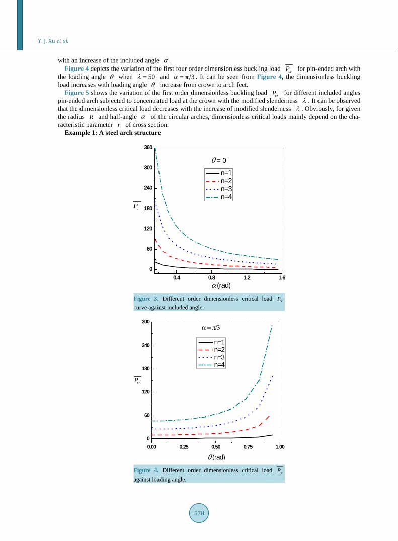
with an increase of the included angle α . Figure 4 depicts the variation of the first four order dimensionless buckling load crP for pin-ended arch with
the loading angle θ when 50λ = and π 3α = . It can be seen from Figure 4, the dimensionless buckling load increases with loading angle θ increase from crown to arch feet.
Figure 5 shows the variation of the first order dimensionless buckling load crP for different included angles pin-ended arch subjected to concentrated load at the crown with the modified slenderness λ . It can be observed that the dimensionless critical load decreases with the increase of modified slenderness λ . Obviously, for given the radius R and half-angle α of the circular arches, dimensionless critical loads mainly depend on the cha-racteristic parameter r of cross section.
Example 1: A steel arch structure
0.4 0.8 1.2 1.60
60
120
180
240
300
360
crP
n=1 n=2 n=3 n=4
α (rad)
θ = 0
Figure 3. Different order dimensionless critical load crP curve against included angle.
Figure 4. Different order dimensionless critical load crP against loading angle.
0.00 0.25 0.50 0.75 1.000
60
120
180
240
300α = π/3
θ (rad)
crP
n=1 n=2 n=3 n=4

Y. J. Xu et al.
579
Arch structures are widely used in the engineering practice, especially in a coal mine roadway support. In this paper, a steel arch structure of roadway support in a certain coal mine is discussed, half included angle of arch is
π 4α = , the radius of arch is 2.1425 mR = , moment inertia is 8 4612 10 mI −= × , Young’s modulus of elas- ticity is 112.1 10E = × and Poisson ratio is 0.3µ = .
In order to compare the analytic solutions with numerical results, eigenvalue buckling analysis of the finite element software ANSYS is used to predict the critical loads. Table 1 lists the first three order critical loads of eigenvalue buckling analysis and the first four order critical loads of theoretical analysis with different loading angles. Figure 6 shows that different order critical loads vary with different loading positions. It can be ob- served that, the second order critical load of theoretical analysis corresponds to the lowest critical load of eigen- value buckling analysis, and each order results agree very well, which verifies the reasonableness of theory analysis. Table 2 shows the relative error of critical loads of theoretical analysis. It also can be seen that the re- sults of theoretical analysis and eigenvalue analysis agree with each other very well.
When n = 1, π 2 2, sin 2 cos 2 .k n v A Bα α α= = = + From the boundary conditions π 4, 0vϕ = = , namelysin π 2 cos π 2 0A B+ = , the integral constants can be determined, and the radial displacement can be obtained
Figure 5. Dimensionless critical load crP curve of different included angles against modified slenderness.
0 10 20 30 400
20000
40000
60000
80000
100000
120000
Pcr (
kN)
θ ( 0 )
Eigenvalue 2nd Eigenvalue 3rd Eigenvalue 4th Theory n=1 Theory n=2 Theory n=3 Theory n=4
Figure 6. Different order critical loads vary with loading lo-cation.
0 20 40 60 800
8
16
24
32
crP
θ = 0
α=π/6 α=π/4 α=π/3
λ

Y. J. Xu et al.
580
Table 1. Different order critical loads (kN).
θ (˚) 1st order 2nd order 3rd order 4th order
Theory Theory Numerical Theory Numerical Theory Numerical
0 845.0 4225.1 4482.4 9858.6 9980.0 17745.6 17977.0
5 857.7 4288.5 4542.9 10006.6 10162.0 18012.0 18213.0
10 898.0 4490.2 4737.8 10477.7 10713.0 18859.1 19036.0
15 973.0 4865.1 5111.9 11352.0 11668.0 20433.6 20711.0
20 1097.9 5489.5 5758.2 12808.8 13167.0 23056.0 23552.0
25 1305.3 6526.5 6869.0 15228.5 15603.0 27411.9 28122.0
30 1673.2 8366.0 8896.4 19520.7 19970.0 35137.2 36067.0
35 2436.3 12183.5 13197.0 28428.1 29263.0 51170.7 52817.0
40 4762.2 23814.6 26549.0 55551.2 58347.0 100078.5 105660.0
Table 2. Relative error of theoretical and numerical results (%).
θ (˚) 2nd 3rd 4th
0 5.74 1.22 1.29
5 5.60 1.53 1.10
10 5.23 2.20 0.93
15 4.83 2.71 1.34
20 4.67 2.72 2.11
25 4.99 2.40 2.53
30 5.96 2.25 2.58
35 7.68 2.85 3.12
40 10.30 4.79 5.28
as cos 2v B ϕ= , the corresponding buckling mode is shown in Figure 7(a). Similarly, when n = 2, the radial displacement is sin 4v A ϕ= , and corresponding buckling mode is shown in Figure 7(b). When n = 3, the radi- al displacement is cos 6v B ϕ= , and corresponding buckling mode is shown in Figure 7(c). When n = 4, the radial displacement is cos 6v B ϕ= , and corresponding buckling mode is shown in Figure 7(d). The buckling modes of numerical results obtained by eigenvalue buckling analysis are shown in Figure 8. The lowest order buckling mode corresponds to anitsymmetric buckling form with two semi waves, and the third order buckling mode corresponds to symmetric buckling form with three semi waves, and so on. For the third-order symmetric buckling mode, there are two deformations: (a) vault sink and two sides crush to rock; (b) vault uplift and two sides crush to the roadway. Both possibly occur in practice. It also can be seen that the lowest-order buckling mode of eigenvalue buckling analysis corresponds to the second order buckling mode.
Traditionally, two buckling analysis techniques are available in ANSYS for predicting the buckling load and buckling mode shape of a structure, nonlinear buckling analysis and eigenvalue (or linear) buckling analysis. The eigenvalue buckling analysis predicts the theoretical buckling strength of an ideal linear elastic structure. This method corresponds to the textbook approach of elastic buckling analysis. The nonlinear buckling analysis employs a nonlinear static analysis with gradually increasing loads to seek the load level at which the structure becomes unstable. If not inflicting any initial defects on the ideal perfect structure, geometry nonlinear analysis couldn’t predict the critical load accurately. Generally in engineering, the method of imposing certain initial de-

Y. J. Xu et al.
581
(a) (b)
(c) (d)
Figure 7. Buckling modes of theoretical analysis. (a) 1n = , 1st order mode; (b) 2n = , 2nd order mode; (c) 3n = , 3rd order mode; (d) 4n = , 4th order mode.
(a) (b)
(c) (d)
Figure 8. Buckling modes of eigenvalue buckling analysis by ANSYS. (a) 2nd order mode; (b) 3rd order mode; (c) 3rd order mode; (d) 4th order mode. fects is adopted to approximate the actual critical load of structures, but this method will change the geometrical model. In addition to the above two numerical methods, we put forward a transient analysis method for buckling

Y. J. Xu et al.
582
analysis [19], and the dynamic response of the loading process and inertial iterative process could be regarded as a kind of tiny disturbance.
Table 3 shows second order buckling critical load of several different analysis methods. Here, we impose 5‰ maximum displacement of eigenvalue buckling analysis as initial imperfection in geometrical nonlinear analysis. Figure 9 shows critical loads by different methods vary with different loading positions.
5. Conclusions The following conclusions can be drawn: 1) This paper gives a theoretical analysis of the local instability of circular arches subjected to a concentrated
load. 2) The virtual work method is used to derive the equilibrium equation for pin-ended circular arches, and it is
shown that the axial force is nearly constant along the circumference of the circular arches subjected to a concentrated load.
0 10 20 30 400
5000
10000
15000
20000
25000
30000
35000
Pcr (
kN)
θ ( 0 )
Eigenvalue 2nd Theory n=2 Transient Nonlinear Nonlinear(imperfection)
Figure 9. Second-order critical loads of different methods vary with loading location.
Table 3. Second-order critical loads of different methods (kN).
θ (˚) Theory Eigenvalue Transient Nonlinear (Imperfection) Nonlinear
0 4225.1 4482.4 4221 4130.98 4844.52
5 4288.5 4542.9 3102.72 3087.43 3102.9
10 4490.2 4737.8 2805.12 2801.46 2805.33
15 4865.1 5111.9 2773.92 2772.19 2774.4
20 5489.5 5758.2 2995.92 2994.05 2996.01
25 6526.5 6869.0 3616.08 3606.86 3616.1
30 8366.0 8896.4 5160.6 5132.29 5160.85
35 12183.5 13197.0 9781.2 9681.77 9782.44
40 23814.6 26549.0 12463.2 12208.8 12467.2

Y. J. Xu et al.
583
3) Based on force methods, the primary eigenfunction equation is derived and solved, and the approximate analytical solutions of critical instability loads are obtained. The buckling load increases with loading angle increasing from crown to arch feet and the critical load decreases with increasing of modified slenderness.
4) For a practical steel arch structure of the roadway support in a certain coal mine in the south of China, the theory predictions results agree very well with the eigenvalue buckling analysis results of ANSYS.
5) The analytical solutions and numerical results prove that the method and approximate theoretical analysis formula in this paper are practical and feasible, and can be used directly in engineering practices in the eval- uation of the critical loads of arches.
References [1] Timoshenko, S.P. and Gere, J.M. (1961) Theory of Elastic Stability. 2nd Edition, McGraw-Hill, New York. [2] Vlasov, V.Z. (1961) Thin-Walled Elastic Beams. 2nd Edition, Israel Program for Scientific Translation, Israel. [3] Simitses, G.J. (1976) An Introduction to the Elastic Stability of Structures. Prentice-Hall, Englewood Cliffs. [4] Bradford, M.A., Uy, B. and Pi, Y.L. (2002) In-Plane Stability of Arches under a Central Concentrated Load. Journal of
Engineering Mechanics, 128, 10-20. http://dx.doi.org/10.1061/(ASCE)0733-9399(2002)128:7(710) [5] Gjelsvik, A. and Bodner, S.R. (1962) The Energy Criterion and Snap Buckling of Arches. Journal of the Engineering
Mechanics, ASCE, 88, 87-134. [6] Schreyer, H.L. and Masur, E.F. (1966) Buckling of Shallow Arches. Journal of the Engineering Mechanics, ASCE, 92,
1-20. [7] Pi, Y.L. and Trahair, N.S. (1999) In-Plane Buckling and Design of Steel Arches. Journal of the Structural Engineering,
ASCE, 125, 1291-1298. http://dx.doi.org/10.1061/(ASCE)0733-9445(1999)125:11(1291) [8] Pi, Y.L., Bradford, M.A. and Uy, B. (2002) In-Plane Stability of Arches. International Journal of Solids and Structures,
39, 105-125. http://dx.doi.org/10.1016/S0020-7683(01)00209-8 [9] ABAQUS Standard User’s Manual. Copyright 2009, Karlsson and Sorensen Inc. [10] ANSYS User’s Manual 12.0. Copyright 2009 SAS IP, Inc. [11] Rajasekaran, S. and Padmanabhan, S. (1989) Equations of Curved Beams. Journal of Engineering Mechanics, 115,
1094-1111. http://dx.doi.org/10.1061/(ASCE)0733-9399(1989)115:5(1094) [12] Kang, Y.J. and Chai, H.Y. (1994) Thin-Walled Curved Beams. II: Analytical Solutions for Buckling of Arches. Jour-
nal of Engineering Mechanics, 120, 2102-2125. http://dx.doi.org/10.1061/(ASCE)0733-9399(1994)120:10(2102) [13] Cheng, J. and Jiang, J.J. (2003) Ultimate Load-Carrying Capacity of Long-Span Steel Arch Bridges. Engineering Me-
chanics, 20, 7-10. (in Chinese) [14] Pi, Y.L. and Trahair, N.S. (1996) In-Plane Inelastic Buckling and Strengths of Steel Arches. Journal of the Structural
Engineering, ASCE, 122, 734-747. http://dx.doi.org/10.1061/(ASCE)0733-9445(1996)122:7(734) [15] Pi, Y.L. and Trahair, N.S. (1998) Non-Linear Buckling and Postbuckling of Elastic Arches. Engineering Structures, 20,
571-579. http://dx.doi.org/10.1016/S0141-0296(97)00067-9 [16] Long, Y.Q. and Bao, S.H. (2000) Structure Mechanics. Higher Education Press, Beijing. (in Chinese) [17] Ding, J.G. (2003) The Analysis of Stability on Cable-Arch Structure Acted by a Concentrated Load at the Middle Point
of a Span. Journal of Nanjing University of Science and Technology, 27, 214-217. [18] Xiang, H.F. and Liu, G.D. (1991) Stability and Vibration of arch Structure. China Communication Press, Beijing. (in
Chinese) [19] Gui, X.M., Xu, Y.J. and Zhao, B. (2011) Finite Element Analysis on Stability of u-Type Arch. Proceedings of the 20th
National Conference on Structure Engineering, Ningbo, 5-7 November 2011, 182-186. (in Chinese)