In-picture audio meter - ChromatecManual.pdf · In-picture audio meter Series III User instructions...
13
Distributed Worldwide: Michael Stevens & Partners Ltd Invicta Works Elliott Road Bromley Kent BR2 9NT UK Tel: +44 (0)20 8460 7299 Fax: +44 (0)20 8460 0499 E-mail: sales @michael-stevens.com Web:http://www.chromatec.com SD-4 In-picture audio meter Series III User instructions From the range of in-picture audio meters by Chromatec
-
Upload
truongquynh -
Category
Documents
-
view
219 -
download
1
Transcript of In-picture audio meter - ChromatecManual.pdf · In-picture audio meter Series III User instructions...

Distributed Worldwide:Michael Stevens & Partners LtdInv icta Works Ell iott Road Bromley Kent BR2 9NT UKTel: +44 (0)20 8460 7299 Fax: +44 (0)20 8460 0499E-ma i l : sales@m ichael -stevens.comWeb:http:/ /www.chromatec.com
SD-4In-picture audio meterSeries III
User instructions
From the range of in-picture audio meters by Chromatec
Administrator

SD-4In-picture audio meter
The Model SD-4D is a serial digital in-picture audio meter for displaying upto four channels of audio in bargraph form. The audio may be derived fromany one of the four embedded audio groups, from two pairs of externalAES/EBU inputs or two pairs of external analogue inputs. The audio bar-graphs and on-screen data are mixed in the digital domain with the outgo-ing SDI signal and may be converted to provide both YUV/RGB and com-posite video outputs also with superimposed bargraphs. Two AES/EBU out-puts together with four corresponding analogue outputs are provided so thatthe incoming audio, whether embedded or AES/EBU may be converted toanalogue.A comprehensive on-screen menu allows the user to configure the SD-4according to requirements including bargraph height, bar colours, positionon screen, level references, etc. Any one of the four embedded audiogroups or external audio sources may be displayed as audio level bar-graphs together with sum & difference (M&S) meters, Loudness* metersand two phase correlation meters. Six standard meter scales and their cor-responding ballistics are available together with VU superimposed on PPM.Alarms are provided for audio loss, carrier loss, over level, Loudness overand sustained anti-phase with TTL outputs and on-screen indication in analarm condition. There is provision for a wired remote control, duplicatingthe operation of the front panel buttons.*Based on the Thames Television – ITC standard.
Model overview
Front panel buttons
Insert onThe "Insert On" button switches the bargraphs on or off according to the bargroups pre-selected from the Menu and at the previously set fade level.When in the Menu mode the Insert button also acts as a "shift" key whenchanging values in the third column.
Function/fadeThe Fade buttons determine the mix level of the bargraphs superimposedon the outgoing video and operate only when the unit is locked (with the redLED off). When the unit is unlocked and in the Menu mode, these buttonsare used to move the cursor up or down the Menu line in order to select afunction.
LockThe "Lock" button performs three functions depending in which mode theunit is operating. When in the locked mode with the red LED off, pressingthe button briefly will reset the peak hold indicators and loudness
1
SD-4In-picture audio meter
alarm/latch. Unlock is activated by keeping the button pressed for about 3seconds after which the red LED will be lit and the on-screen Menuappears, disabling the Fade function. While in the Menu mode someactions require confirmation which is carried out by pressing both Lock andInsert buttons simultaneously (see below). After carrying out changes with-in the Menu, pressing the Lock button again will save the settings andreturn the SD-4 to the normal meter mode.
Select parameterWhen the unit is unlocked the Select Parameter buttons are used tochange the system settings depending on the Menu line selected. In thenormal locked mode the “Select Parameter” buttons may be pressed,briefly, together with the “Lock” button in order to change the televisionstandard of the internal black generator.
In order to change the numerous parameters of the SD-4 it is necessary toenter the system Menu by pressing the Lock button for approximately 3secs, whereupon the red LED above the Lock button will light and theMenu will appear on-screen. In all cases the “Select Parameter” buttonsselect the value shown in the centre column of the menu. Whereapplicable, the adjustable values shown in the third column are carried outby using the “Insert” button as a “shift” key together with the “SelectParameter” buttons. Those menu lines that have a red flashing cursorrequire confirmation of an action which is carried out by pressing both the"Insert" and "Lock" buttons simultaneously, whereupon the cursor stopsflashing. See following Menu pages.
Note - The order of the following menu lines may vary according to the software release of your SD-4.
Menu Page 1
USER CONFIGURATION SELECTThe SD-4 has two user memories, User 1 and User 2, where allconfiguration settings are stored. Depending which user is currently shownor subsequently selected, exiting the menu will store any changes made inthe menu to that user. In the unlikely event that a system reset is requiredthen all user settings will be returned to the factory default settings.
USER CONFIGURATION COPY/RESETIt is possible to copy one user configuration to the other user or reset usersto the factory default settings. Each option has a flashing red cursorindicating that confirmation of this action is required. This is carried out bypressing the Insert and Lock buttons simultaneously whereupon the redcursor will stop flashing.
METER DISPLAY HORIZ POSITIONHorizontal adjustment of the whole audio meter display (including phasemeters if displayed) may be adjusted. The menu marker provides anapproximation of it’s relative position on screen.
2
System Menu

SD-4In-picture audio meter
METER DISPLAY VERT POSITIONVertical adjustment of the whole meter display (including phase meters andtimecode reader if displayed) may be adjusted. The menu marker providesan approximation of it’s relative position on screen.
METER GROUP HEIGHTThe main bargraph group height may be set to Normal (full height), Half orQuarter depending on the vertical meter resolution required.
METER GROUPS VERT POSITIONAllows vertical adjustment of the bargraph groups. The menu markerprovides an approximation of their relative position on screen.
AUDIO SOURCE SELECTThe SD-4 may be switched to display audio derived from the incoming SDIvideo feed (embedded), external AES/EBU or external analogue. In all cases amaximum of four channels may be displayed at any one time. When viewingde-embedded audio it is possible to select one of the four groups available.
Menu Page 1/2
METER GROUP [X] DISPLAY Up to four bargraph groups, A,B,C & D may be displayed, by default A & Bare located to the left of the screen and C & D to the right. Each of thesegroups can be assigned to display Level, Sum & Difference, Sum only andLoudness, or turned off.
METER GROUP [X] CHANNELS ASSIGNAny combination of channel assignments may be selected.
METER GROUP [X] HORIZ POSITIONAllows horizontal adjustment of the bargraph group. The menu markerprovides an approximation of it’s relative position on screen. When movinga group and another group is in the way, one group will "push" the otherone along. However, if a group is opened and the position conflicts with agroup already being displayed then both groups will be displayed in outlinemode only until one group is moved clear of the other.
METER GROUP [X] SCALES POSITIONWhichever scale is selected (see Menu p4), it may be placed to the left orright of the bargraph or turned off.
Menu Page 3
BAR WIDTHWhen selecting this line a small red cursor appears on the bargraph at it’sbase according the bargraph selected. The bargraph width value (in pixels)may then be changed by using the Insert button as a "shift" key togetherwith the Select Parameter buttons. Selecting "All Bars" applies the valuechosen to all bargraphs.
3

SD-4In-picture audio meter
BAR SPACINGWhen selecting this line a small red cursor appears between the bargraphsat their base according the group selected. The bargraph spacing value (inpixels) may be changed by using the Insert button as a "shift" key togetherwith the Select Parameter buttons. Selecting "All Groups" applies the valuechosen to all Groups.
BAR COLOUR OVER-RANGEThe "Over-Range" portion of the bargraph is at the top. The requiredbargraph is selected and then colours may be changed by using the Insertbutton as a "shift" key together with the Select Parameter buttons.Selecting "All" applies the colour chosen to all bargraphs.
BAR COLOUR UPPER-RANGEThe "Upper-Range" portion of the bargraph is at the centre. The requiredbargraph is selected and then colours may be changed by using the Insertbutton as a "shift" key together with the Select Parameter buttons.Selecting "All" applies the colour chosen to all bargraphs.
BAR COLOUR LOWER-RANGEThe "Lower-Range" portion of the bargraph is at the bottom. The requiredbargraph is selected and then colours may be changed by using the Insertbutton as a "shift" key together with the Select Parameter buttons.Selecting "All" applies the colour chosen to all bargraphs.
BAR BACKGROUND COLOURThe required bargraph is selected and then colours may be changed byusing the Insert button as a "shift" key together with the Select Parameterbuttons. Selecting "All" applies the colour chosen to all bargraphs.
METER GROUP BACKGROUND COLOURThe required background colour may be chosen.
METER GROUP SCALES COLOURThe required scales colour may be chosen.
METER GROUP LABELS COLOURThe labels are situated at the base of the bargraph groups. The requiredcolour may be chosen.
METER SCALES SELECTBy default standard AES/EBU digital scales are displayed. However, thesemay be substituted with any of five internationally recognised analoguescales (together with their respective ballistics). In this case it is necessaryto set the Digital/Analogue Scale Reference as shown below.
ANALOGUE UPPER-RANGE POINTThis value sets the upper colour transition point of the bargraph whendisplayed with an analogue scale.
4

SD-4In-picture audio meter
ANALOGUE LOWER-RANGE POINTThis value sets the lower colour transition point of the bargraph whendisplayed with an analogue scale.
Menu Page 4
ANALOGUE 0dB REFERENCEThe selected value is the level (in dBu) of the analogue input signal that isto be displayed at 0dB when using an analogue scale. This value shouldalso be taken into account when displaying an analogue input signal on theAES/EBU digital scale as the relationship between the analogue and digitalscale is fixed by the Digital/Analogue Scale Ref (see above).DIGITAL UPPER-RANGE POINTThis value sets the upper colour transition point of the bargraph whendisplayed with the AES/EBU digital scale.
DIGITAL LOWER-RANGE POINTThis value sets the lower colour transition point of the bargraph whendisplayed with the AES/EBU digital scale.
DIGITAL/ANALOGUE SCALE REFIt is necessary to set this value when displaying a digital input signal on ananalogue scale or an analogue input signal on a digital scale. TheEuropean default value is –18dB whereas in the USA this is usually –20dB.
PHASE BAR OPERATING MODEIn the Independent mode both phase correlation bars appear as horizontalbargraphs. In the Inc Group mode they are included as a vertical bargraphincluded in the main group of the respective audio level meter.
PHASE BAR [X] ASSIGNAssigns Phase Bar A to the selected channels or bargraph group.
PHASE BAR [X] HORIZ POSITIONAllows horizontal adjustment of the selected phase bar. The menu markerprovides an approximation of it’s relative position on screen.
PHASE BAR [X] VERT POSITIONAllows vertical adjustment of the selected phase bar. The menu markerprovides an approximation of it’s relative position on screen.
PHASE BARS MAX HOLD ENABLEA maximum hold cursor may be selected to indicate any negative phaseexcursion. This may be reset by briefly pressing the Lock button when inthe normal operating mode.
PHASE BAR COLOURSAfter selecting Phase In or Phase Out the colours may be selected bypressing the Insert button as a "shift" key together with the Lock button.
5

SD-4In-picture audio meter
Menu Page 5
SUM LEVEL SETDepending on operating requirements the sum level may be adjusted.
PEAK HOLD ENABLEThe peak hold indicator is a small coloured line located at the top of eachaudio level meter and may be turned off if not required. All signal peaksare displayed for the time period selected unless updated by a higher peakin the meantime. If Infinite is selected then the peak levels of a completeprogramme may be monitored. Reset is carried out by briefly pressing thelock button when in the normal operating mode.
PEAK HOLD INDICATOR COLOURThe required indicator colour may be chosen.
SUPERIMPOSE VU METERWhen using a PPM scale (analogue or digital) a VU meter may besuperimposed enabling both peak and average readings simultaneously.This may be displayed as a split bargraph or a small coloured bar.
SUPERIMPOSED VU COLOURThe required indicator colour may be chosen for the selected channels.
LOUDNESS DEFAULTSThe loudness defaults are those as originally developed by Thames Televisionin conjunction with the ITC and commonly accepted as the "Loudness"standard. However, some operating requirements may dictate modification ofthese default parameters in which case they may be switched off.
LOUDNESS OVER-RANGE POINTThis value sets the single colour transition point of the Loudness bargraph.
LOUDNESS INTEGRATION TIMEThis value determines the integration time of the Loudness bargraph.
LOUDNESS ALARM ENABLESeparate alarms are provided for both Loudness meters. These may beactivated individually, both together or turned off.
LOUDNESS ALARM SET LEVELDetermines the point on the loudness bargraph at which the alarm isactivated. A red flashing alarm indicator appears at the top of the bargraphtogether with small red alarm latch indicators (see below).
LOUDNESS ALARM SET LATCHThe value selected determines how long an alarm condition remainsactivated before automatically resetting. When set to Infinite any alarmcondition remains activated until manually reset. There are eight Latchindicators, each one turning on when another alarm condition has
6

SD-4In-picture audio meter
7
occurred. If and when all eight indicators are displayed a ninth alarmcondition will result in all eight indicators flashing on/off. The Latchcondition may be reset by briefly pressing the Lock button (when in normaloperating mode).
Menu Page 6
ALARM INDICATORSThe on-screen alarm indicators comprise small coloured squares placed atthe top of the respective bargraph groups. These are colour coded foreach type of alarm condition. They may be hidden if not required.
ALARMS MASTER RESETAll alarms may be reset. The flashing red cursor indicates that confirmationof this action is required. This is carried out by pressing the Insert and Lockbuttons simultaneously whereupon the red cursor will stop flashing.
ALARMS AUTO RESETWhen activated, in an alarm condition the relevant alarms will automaticallybe reset after the selected time period subject to no further alarmconditions occurring in the interim. The timing of each individual alarm isindependent and is taken from the point that the alarm is triggered or re-triggered.
ALARM, SDI LOSS ENABLEWhen turned on, this alarm will be triggered if the SDI input is lost.
ALARM, CARRIER LOSS ENABLEWhen turned on, this alarm will be triggered if both of the AES/EBU inputsare lost.
SET TIMESets the time before the alarm is triggered when the AES/EBU inputs carrier signals are lost.
ALARM, AUDIO OVER ENABLEWhen turned on, this alarm will be triggered if the selected audio channelsexceed the selected level.
SET LEVELThe range of levels shown will change depending whether the scale displayed is analogue or digital. The correlation will change according to the value set in the Digital/Analogue Scale Ref line of the menu.
ALARM, AUDIO LOSS ENABLEWhen turned on, this alarm will be triggered if the selected audio channelsdo not reach the selected threshold within the time set below.
SET TIMESets the time before the alarm is triggered.SET THRESHOLDSets the threshold level below which the alarm will be triggered.

SD-4In-picture audio meter
ALARM, ANTI-PHASE ENABLEWhen turned on, this alarm will be triggered if the selected phase bars areout of phase according to the parameters set below.
SET TIMESets the time before the alarm is triggered.SET THRESHOLDSets the threshold in degrees beyond which the alarm will be triggered.
Menu Page 7
AES/EBU OVERSAMPLES STATUSThis is a status page showing the number of oversamples per channel andverification that the incoming AES/EBU signal is error free. The samplingfrequency is also displayed. These values may be reset by pressing theInsert and Lock buttons simultaneously whereupon the red cursor will stopflashing.
Menu Page 8
VIDEO MODEThe component video output may be set to YUV or RGB. The SDI andcomposite outputs are independent of this setting.
VIDEO DISPLAYIn the Auto mode, if the incoming SDI feed is lost the SD-4 willautomatically switch to internally generated black enabling the externalanalogue and AES/EBU audio still to be viewed. If the SDI signal isreinstated the SD-4 will automatically revert to displaying the video fromthis feed. When set to Internal, any audio feed (SDI embedded, AES/EBUor analogue – as selected in Page 1 of the menu) may be viewed oninternal black if in-picture audio metering is not required. In this mode, bydefault, the fade level of the bargraphs is set to maximum but they maysubsequently be faded down if required.
VIDEO STANDARD INTERNALIf the SD-4 is used as a dedicated audio meter in Internal mode only it willbe necessary to set the outputs to 525 line NTSC or 625 line PAL.Although the incoming SDI video standard is detected automatically it isstill necessary to set the internal black generator manually so that if theincoming video is lost (and Auto mode is selected) then the SD-4 willoutput the required television standard.NOTE! It is also possible to change the internal black generator’s standardby briefly pressing the Lock and both Select Parameter buttonssimultaneously when the unit is in the normal operating mode.
NTSC PEDESTALThe NTSC pedestal of the outgoing video may be set on or off.
8
SD-4In-picture audio meter
VIDEO FUNCTIONSVarious video test functions may be selected. After use, press the Lockbutton for a few moments to return to the system menu and then to turn offthe test functions.
DATA PORT 1 ASSIGNAssign the data port to the required external device.
TIMECODE READER ENABLENOTE! This is a system option. If fitted, either LTC or VITC may beselected. LTC is derived externally (see connectors). If present on theinternal video, VITC may be displayed.
TIMECODE HORIZONTAL POSITIONAllows horizontal adjustment of the timecode reader. The menu markerprovides an approximation of it’s relative position on screen.
TIMECODE VERTICAL POSITIONAllows vertical adjustment of the timecode reader. The menu markerprovides an approximation of it’s relative position on screen.
TIMECODE BACKGROUND COLOURThe required background colour may be chosen.
TIMECODE NUMBERS COLOURThe required numbers colour may be chosen.
Master Reset is achieved by turning off the power for a few seconds, andturning it back on again while pressing both Fade/Function buttons until thebargraphs appear. A Master Reset is employed to return all settings to thefactory default, or it may be carried out in the unlikely event that the unitfails to respond to the front panel push buttons. Please note that all usersettings will be lost.
SDIThe SD-4 is normally connected in-line with an SDI monitor feed via theappropriate 75ohm BNC connectors and is designed to accept 525 or 625line SMPTE 259M serial digital video. A loop-through copy output is alsoprovided.
Analogue videoBoth YUV component and composite outputs are on 75ohm BNCconnectors. These are an analogue copy of the SDI input plussuperimposed audio bargraphs.
AudioTwo pairs of AES/EBU and two pairs of analogue inputs are provided toaccompany the SDI when separate audio and video feeds are employed.
9
Connections
Master Reset

SD-4In-picture audio meter
Two pairs of AES/EBU outputs are available which may comprise thecorresponding AES/EBU inputs or de-embedded audio from any of the fouravailable groups contained in the SDI feed. Four analogue outputs are alsoprovided.
The SD-4 will operate from a nominal 115VAC or 230VAC mains supply.The mains input voltage is selected by the switch located on the rear panelnext to the power inlet.
Rear panel layout
10
Power

SD-4In-picture audio meter
11
Connection details
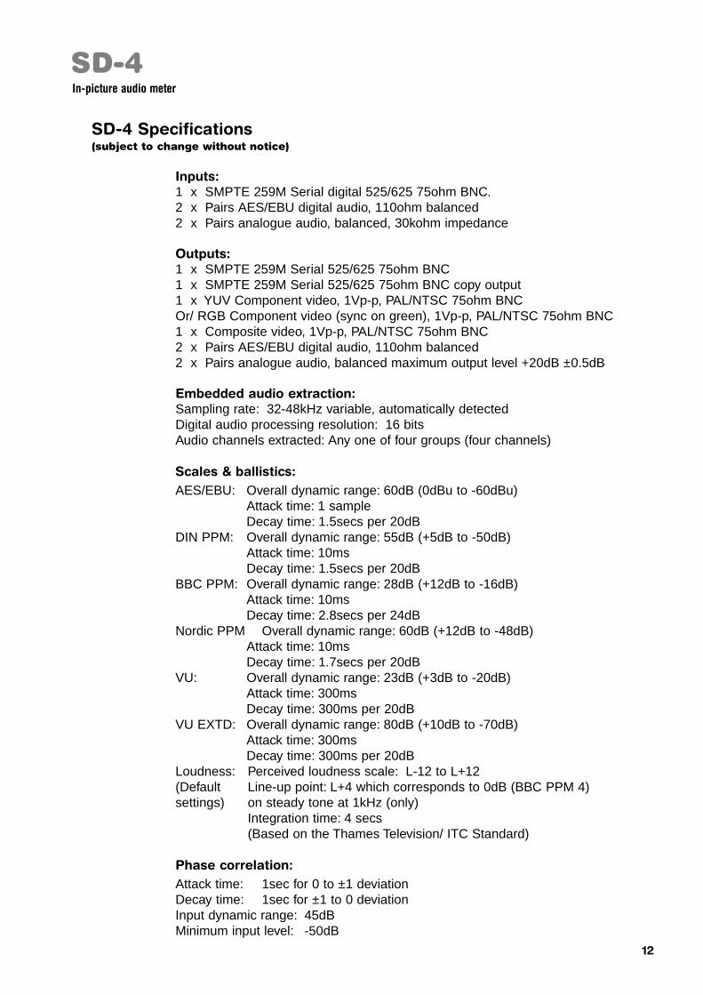
SD-4 Specifications(subject to change without notice)
Inputs:1 x SMPTE 259M Serial digital 525/625 75ohm BNC.2 x Pairs AES/EBU digital audio, 110ohm balanced2 x Pairs analogue audio, balanced, 30kohm impedance
Outputs:1 x SMPTE 259M Serial 525/625 75ohm BNC 1 x SMPTE 259M Serial 525/625 75ohm BNC copy output1 x YUV Component video, 1Vp-p, PAL/NTSC 75ohm BNCOr/ RGB Component video (sync on green), 1Vp-p, PAL/NTSC 75ohm BNC1 x Composite video, 1Vp-p, PAL/NTSC 75ohm BNC2 x Pairs AES/EBU digital audio, 110ohm balanced2 x Pairs analogue audio, balanced maximum output level +20dB ±0.5dB
Embedded audio extraction:Sampling rate: 32-48kHz variable, automatically detectedDigital audio processing resolution: 16 bitsAudio channels extracted: Any one of four groups (four channels)
Scales & ballistics:AES/EBU: Overall dynamic range: 60dB (0dBu to -60dBu)
Attack time: 1 sampleDecay time: 1.5secs per 20dB
DIN PPM: Overall dynamic range: 55dB (+5dB to -50dB)Attack time: 10msDecay time: 1.5secs per 20dB
BBC PPM: Overall dynamic range: 28dB (+12dB to -16dB)Attack time: 10msDecay time: 2.8secs per 24dB
Nordic PPM Overall dynamic range: 60dB (+12dB to -48dB)Attack time: 10msDecay time: 1.7secs per 20dB
VU: Overall dynamic range: 23dB (+3dB to -20dB)Attack time: 300msDecay time: 300ms per 20dB
VU EXTD: Overall dynamic range: 80dB (+10dB to -70dB)Attack time: 300msDecay time: 300ms per 20dB
Loudness: Perceived loudness scale: L-12 to L+12(Default Line-up point: L+4 which corresponds to 0dB (BBC PPM 4) settings) on steady tone at 1kHz (only)
Integration time: 4 secs(Based on the Thames Television/ ITC Standard)
Phase correlation:Attack time: 1sec for 0 to ±1 deviationDecay time: 1sec for ±1 to 0 deviationInput dynamic range: 45dBMinimum input level: -50dB
SD-4In-picture audio meter
12