IN-LINE CENTRIFUGAL FAN - Chief Agri/Industrial · PDF filein-line centrifugal fan ation & g...
45
IN-LINE CENTRIFUGAL FAN INSTALLATION & OPERATINGMANUAL P/N 779876 Rev 0 Model Number ILC18 ILC24 ILC28
Transcript of IN-LINE CENTRIFUGAL FAN - Chief Agri/Industrial · PDF filein-line centrifugal fan ation & g...

IN-LINE CENTRIFUGAL FAN
IN
ST
AL
LA
TIO
N &
OP
ER
AT
IN
GM
AN
UA
L
P/N
779876 R
ev 0
Model Number
ILC18
ILC24
ILC28

Chief Industries, Inc. 800-359-7600 TOC – 779876 Page 2
C H I E F I N D U S T R I E S , I N C . – A G R I / I N D U S T R I A L D I V I S I O N
Installation Manual
Chief Industries, Inc. 4400 East 39th Street • PO Box 848
Kearney, NE 68847 Phone 800.359.7600
For more information about Chief Industries, Inc. and additional products or services please visit our website
www.agri.chiefind.com
WARNING: If the information in this manual is not followed exactly, a
fire or explosion may result causing property damage, personal
injury or loss of life.
- Do not store or use gasoline or other flammable vapors and
liquids in the vicinity of this or any other appliance.
- WHAT TO DO IF YOU SMELL GAS
o Do not try to light any appliance.
o Extinguish any open flames.
o Do not touch any electrical switch.
o Immediately call your gas supplier. Follow the gas
supplier’s instructions.
o If you cannot reach your gas supplier, call the fire
department.
- Installation and service must be performed by a qualified
installer, service agency or the gas supplier.
WARNING: Improper installation, adjustment, alteration, service or
maintenance can cause property damage, injury or death. Read the
installation, operating and maintenance instructions thoroughly
before installing or servicing this equipment.
FOR YOUR SAFETY
The use and storage of gasoline and other flammable vapors and
liquids in open containers in the vicinity of this appliance is
hazardous.

Chief Industries, Inc. 800-359-7600 TOC – 779876 Page 3
Table of Contents
Introduction ........................................................................... 4
Model Number Description .............................................................. 4
Packing List ..................................................................................... 5
Before You Begin ................................................................. 6
Safety and Precautions ..................................................... 8
Fan and Control Enclosure Components ................... 12
Accessories: .................................................................................. 12
Specifications: ............................................................................... 12
Explanation of Components: ......................................................... 12
Replacement Parts for Specific Models: ....................................... 15
Conversion Parts: ................................................................................ 15
Fan Location and Foundation ....................................................... 17
Wall Adaptor Installation:...................................................................... 19
Fan Installation .............................................................................. 19
Electrical Installation ..................................................................... 20
Electrical Service Sizing ....................................................................... 20
Electrical Connection at the Fan ........................................................... 22
Wiring Schematics: ........................................................... 25
Voltage Conversions: .................................................................... 30
Operating Instructions ..................................................... 34
Start-Up Procedure: ...................................................................... 34
Shut-Down Procedure: .................................................................. 35
Maintenance ........................................................................ 35
Off Season Operation: .................................................................. 35
Fan Controls: ................................................................................ 35
Fan Motor: ..................................................................................... 36
Fan Blades: ................................................................................... 36
Servicing the Fan: .............................................................. 36
Condition Specific Faults: .............................................................. 37
STANDARD LIMITED WARRANTY......................................... 40

I N - L I N E C E N T R I F U G A L F A N - C S A
Chief Industries, Inc. 800-359-7600 INTRODUCTION -779876 Page 4
Introduction
Thank you for purchasing a Caldwell In-Line Centrifugal Fan. Proper installation will ensure you the best overall experience with your fan and guarantee smooth operation. This manual is for the installation and operation of the Caldwell In-Line Centrifugal Fan that has been 100% factory quality control inspected, field simulated and stress tested prior to shipment. This proprietary information is loaned with the expressed agreement that the drawings and information therein contained are the property of Chief Industries, Inc. and will not be reproduced, copied, or otherwise disposed of, directly or indirectly, and will not be used in whole or in part to assist in making or to furnish any information for the making of drawings, prints or other reproduction hereof, or for the making of additional products or equipment except upon written permission of Chief Industries, Inc. first obtained and specific as to each case. The acceptance of this material will be construed as an acceptance of the foregoing agreement. The technical data contained herein is the most recent available at the time of publication and is subject to modification without notice. Chief Industries, Inc. reserves the right to modify the construction and method of operation of their products at any time without any obligation on their part to modify any equipment previously sold and delivered.
Model Number Description
The fan model nomenclature distinguishes the application of the fan. The information includes a designation of the applicable fan and type of electrical installation utilized. The model number is stamped on the serial number plate and the definition of the model number nomenclature is as follows:
Example: ILC 18 - 1 - 1 - 2
(a) (b) - (c) - (d) - (e)
(a) ILC = In-Line Centrifugal Fan Unit (b) 18 = Housing Diameter (c) 1 = Horsepower (d) 1 = Motor Phase (e) 2 = Motor Voltage

I N - L I N E C E N T R I F U G A L F A N - C S A
Chief Industries, Inc. 800-359-7600 INTRODUCTION -779876 Page 5
Packing List
The shipment should contain the following items. Verify and inspect all items carefully when unpacking and before installing. In case of any shortage, contact your dealer. In case of damage during shipment, file a claim with the carrier.
Quantity Component Description
1 Fan Fan Assembly
1 Warranty Registration Card Bulletin
1 Manual Bulletin (1123)
1 Bolt Bag Assembly
1 Motor Motor Assembly
Note: Before starting the installation of the fan, verify that all items called out on the
packing list have been received.
Please note that this manual, part number 779876 includes and references Bulletin 1123. This manual is for the installation, operation and maintenance of fan models with serial numbers 84A and above, and is effective 5/1/2015.

I N - L I N E C E N T R I F U G A L F A N - C S A
Chief Industries, Inc. 800-359-7600 INTRODUCTION -779876 Page 6
Before You Begin
Read this manual thoroughly before operating this fan. Keep this manual in a location for quick access and reference.
Your Caldwell fan is designed for safe and reliable operation when properly installed. However the fan requires electricity, which when improperly installed or when operated improperly, can be potentially dangerous. Anyone who will operate this unit should read the manual before installing or operating this unit. The following table, provided for your convenience, will aid in verifying that these individuals understand the proper operation of the fan. After completely reading the manual, this table should be filled in.
Date Operator Signature Owner Signature

I N - L I N E C E N T R I F U G A L F A N - C S A
Chief Industries, Inc. 800-359-7600 INTRODUCTION -779876 Page 7
Special Service Note: If you are unable to remedy any service problem after thoroughly studying this manual, contact the dealer from whom you purchased the unit. Your dealer is your first line of service. The following information is required for service:
1. Fan model number: __________________________________
2. Fan serial number: ___________________________________
3. Fan model number: ____________________________________
4. Fan serial number: _____________________________________
5. Line Voltage Measured: _________________________________
6. Approximate operating pressure: __________________________
7. Hours the unit has been in operation: ______________________
8. Diameter and eave height of bin: __________________________
9. Grain depth: _________________________________________
10. Type of grain stored: ___________________________________
11. Moisture content of the grain: ____________________________
12. Dealer purchased from: _________________________________
13. Dealer address and phone number: ________________________
14. Date purchased: _______________________________________
15. Service contractor:
a. Name: ____________________________________________
b. Address: ___________________________________________
c. Phone: ____________________________________________

I N - L I N E C E N T R I F U G A L F A N - C S A
Chief Industries, Inc. 800-359-7600 SAFETY - 779876 Page 8
Safety and Precautions
Your safety and the safety of others is a primary concern to Chief Industries, Inc. This manual was written to assist in the safe installation and operation of the Caldwell Fan.
It is your responsibility as the owner, builder, operator, or supervisor to know what specific requirements, precautions and hazards exist and to make these known to all personnel working with equipment or on the jobsite so that they can observe any necessary safety precautions.
All personnel, including the installation crew, must read and understand the information contained in this manual before starting construction. Chief Industries, Inc. is not responsible or liable for the misuse of equipment or operation of personnel or equipment in an unsafe manner.
Chief Industries, Inc. assumes no liability with respect to proper construction and inspection, assembly, or use of its products established under applicable laws, all of which is the sole responsibility of the purchaser and those authorized for the installation.
Follow all local and federal safety laws and regulations. Verify that all equipment and personnel conform to any applicable jurisdiction regulations.
Work Area Safety Statement
To ensure the safety of all individuals in the work area, only authorized and trained persons shall install, maintain and use the Caldwell Fan.
Under no circumstances should unauthorized individuals be allowed to trespass or be present in the work area.
It shall be the duty of all operators to ensure that the work area is clean, organized and kept free of all debris and tools that might cause an accidental tripping or falling hazard.
Special care should be taken when working from unsafe heights. Common sense dictates that when conditions such as rain or wind prohibit the safe use of equipment, the installation be discontinued.
Chief Industries, Inc. strongly recommends that equipment meeting the current specifications be used, whether the individual operator is required by law to do so or not. Proper climbing equipment and a secured safety harness should be used at all times when performing operations work, installation or maintenance.
Field modifications without the authorization of the manufacturer may present unknown dangers to the operator and must be avoided.
Auxiliary Equipment Safety
You may decide to purchase and install “auxiliary equipment” made by other manufacturers. Chief Industries, Inc. has no control over the design and manufacture of this equipment. In view of this, at a minimum, we suggest you do the following:

I N - L I N E C E N T R I F U G A L F A N - C S A
Chief Industries, Inc. 800-359-7600 SAFETY - 779876 Page 9
1. Obtain, read and understand the instructions and safety cautions of the auxiliary equipment
manufacturer. Be certain that all equipment is installed in agreement with those instructions.
2. Check with Chief Industries, Inc. to verify that your system is designed to support any additional
loads supplied by the auxiliary equipment.
3. Obtain any applicable safety decals from the manufacturer and make certain they are displayed
in a visible location.
4. Make certain that all electrical equipment is properly installed and grounded by a qualified
electrician.
5. Check availability and operation of electrical lock out and emergency stop systems.
6. Be certain that all guards and shields are securely in place.
7. Store all operation / maintenance manuals in a safe place for future use.
Fan Safety
Before operating the unit, perform the following checks:
1. Verify the fan and transition units are bolted securely together. Verify the screen guard is secured in place.
2. Verify the units are wired in compliance with the national electrical code, and the ground wire is of sufficient size to provide lightening protection.
3. Provide sufficient bin exhaust vents or fans, and verify that they are open and operational before starting the drying system. These vents or fans are necessary to provide an exhaust path for moisture laden air (reducing condensation), and also to prevent pressurization of the bin above the grain mass and causing damaging loads on the bin and roof structure. Do not operate units when conditions are such that freezing of the vents could occur.
a. Heed the following warnings:

I N - L I N E C E N T R I F U G A L F A N - C S A
Chief Industries, Inc. 800-359-7600 SAFETY - 779876 Page 10

I N - L I N E C E N T R I F U G A L F A N - C S A
Chief Industries, Inc. 800-359-7600 SAFETY - 779876 Page 11

I N - L I N E C E N T R I F U G A L F A N - C S A
Chief Industries, Inc. 800-359-7600 COMPONENTS - 779876 Page 12
Fan and Control Enclosure Components
The following outlines the accessories, general components and replacement part numbers for the Caldwell fan models.
Accessories:
1. A humidistat is available to cycle the fan according to ambient relative humidity conditions. The humidistat (#736280) can be used with any fan that has 230 volt magnetic controls.
2. Electric humidity controllers are available for most fans. The humidity controller will supply a small amount of heat to lower the relative humidity of the drying air to aid in conditioning of the grain.
3. A Caldwell heater is available for most fans. The gas fired heater is used when a large temperature rise is required. The gas fired heater is a direct combustion unit and should not be used in inhabited areas.
Specifications:
Note: All single phase fan models utilize a permanent split phase capacitor start motor.
Explanation of Components:
Please note the location and general description of the primary components and their function.

I N - L I N E C E N T R I F U G A L F A N - C S A
Chief Industries, Inc. 800-359-7600 COMPONENTS - 779876 Page 13
Control Enclosure Components:

I N - L I N E C E N T R I F U G A L F A N - C S A
Chief Industries, Inc. 800-359-7600 COMPONENTS - 779876 Page 14
Fan Body Components:
The balloon callouts shown in the above illustration specify each component of the fan.
1. Toggle Switch (#710707) - The toggle switch is the fan "On" and "Off" and “Momentary Start” switch.
2. Wheel Assembly – Components that provide a large volume of airflow. This assembly is composed of rotating blades connected to a hub and shaft and is driven by an electric motor.
3. Control Enclosure - The weather proof enclosure to provide protection for the electrical components.
4. Contactor - The electrically controlled switch used for switching the power circuits of the drive motor.
5. Neutral Terminal Block 3 POLE (#850255) - This terminal block is used as a junction block to establish a common neutral for connection of the neutral leads.

I N - L I N E C E N T R I F U G A L F A N - C S A
Chief Industries, Inc. 800-359-7600 COMPONENTS - 779876 Page 15
Replacement Parts for Specific Models:
FAN ORIFICE WHEEL HOUSING CONTROL ENCLOSURE
CONTACTOR HOLDING COIL
ILC18-112 777706 777904 777664 700997 850289 756437
ILC18-132 777706 777904 777664 700997 850297 756437
ILC18-134 777706 777904 777664 700997 850297 752659
ILC18-135 777706 777904 777664 748178 850297 752626
ILC18-312 778688 778720 779371 700997 850289 756437
ILC18-332 778688 778720 779371 700997 850297 756437
ILC18-334 778688 778720 779371 700997 850297 752659
ILC18-335 778688 778720 779371 748178 850297 752626
ILC24-312 777722 778209 777656 700989 850289 756437
ILC24-332 850297 756437
ILC24-334 777722 778209 777656 700989 850297 752659
ILC24-335 777722 778209 777656 748202 850297 752626
ILC24-512 777722 778761 777649 700989 850313 756437
ILC24-532 850305 756437
ILC24-534 777722 778761 777649 700989 850305 752659
ILC24-535 777722 778761 777649 748202 850305 752626
ILC24-712 777748 778241 779645 700989 850313 756437
ILC24-732 850305 756437
ILC24-734 777748 778241 779645 700989 850305 752659
ILC24-735 777748 778241 779645 748202 850305 752626
ILC28-712 776807 778241 777631 700989 850313 756437
ILC28-732 850305 756437
ILC28-734 776807 778241 777631 700989 850305 752659
ILC28-735 776807 778241 777631 748202 850305 752626
ILC28-1012 776807 776831 779520 700989 850354 741124
ILC28-1032 850305 756437
ILC28-1034 776807 776831 779520 700989 850305 752659
ILC28-1035 776807 776831 779520 748202 850305 752626
ILC28-1532 736033 735738 776856 748202 754028 741124
ILC28-1534 736033 735738 776856 700989 754028 752667
ILC28-1535 736033 735738 776856 748202 850305 752626
Conversion Parts:
Converting 230 Volt 3 Phase Fan to 460 Volt 3 Phase Fan
Fan Converted To Holding Coil Change to 230
Volt Contactor Change to
230 Volt
F18-132 F18-134 164064
F18-332 F18-334 164064
F24-532 F24-534 164064

I N - L I N E C E N T R I F U G A L F A N - C S A
Chief Industries, Inc. 800-359-7600 INSTALLATION - 779876 Page 16
F24-732 F24-734 164064
F24-1032 F24-1034 164064
F28-1232 F28-1234 164064
Converting 460 Volt 3 Phase Fan to 230 Volt 3 Phase Fan
Fan Converted To Holding Coil Change to 230
Volt Contactor Change to
230 Volt
F18-134 F18-132 164048
F18-334 F18-332 164048
F24-534 F24-532 850305
F24-734 F24-732 850305
F24-1034 F24-1032 850305
F28-1234 F28-1232 754028

I N - L I N E C E N T R I F U G A L F A N - C S A
Chief Industries, Inc. 800-359-7600 INSTALLATION - 779876 Page 17
Installation Requirements
The following illustration describes the components necessary for a typical installation. The drying unit (fan, heater, and transition) should be located such that the heated air can enter the bin plenum chamber uniformly. Verify all the components needed for the drying system are present. The fan and fan should be located opposite the unloading tube for best air distribution.
Fan Location and Foundation
The following illustration shows a typical installation of 2 drying units and optional plenum controls. If two drying units are used on the same bin, locate them 4’ (1.21m) to within 45° of each other and

I N - L I N E C E N T R I F U G A L F A N - C S A
Chief Industries, Inc. 800-359-7600 INSTALLATION - 779876 Page 18
centered opposite the unloading tube. Locate any humidistat or thermostat control between the two fan units, making sure control senses heat from both units (order kit #9735035).
For proper operation of fan, the units are to be mounted on a level pad. The pad should be the same height as the concrete floor. The size of the pad should be as indicated in the following illustration. The fan should not be anchored to the pad but allowed to float on the pad. When the fan is fastened to the transition or heater the fan legs should be evenly supported on the concrete pad. If necessary use shims under the fan legs so that the fan cannot vibrate.

I N - L I N E C E N T R I F U G A L F A N - C S A
Chief Industries, Inc. 800-359-7600 INSTALLATION - 779876 Page 19
Wall Adaptor Installation:
Alternatively, Caldwell In-Line Centrifugal fans can be mounted to a building wall with a wall adaptor flange. For this type of installation, the concrete fan pad should be located 3.0” (7.62cm) from the building wall and1.5” (3.81cm) below the floor of the building.
Fan Installation:
Before installing the fan please verify the following:
1. The fan blade revolves freely and does not interfere with the housing. If there is interference the motor will need to be shimmed using the instructions found in the maintenance section of this manual. Afterwards check all the fasteners on the fan to verify they have the proper clearance and tighten as required.
2. The fan is installed correctly to provide airflow in the proper direction. Check air flow decals on the fan to verify it is oriented properly. In most applications fans are installed to force air up through the stored grain. This operating condition is referred to as a “positive” aeration system. For this operation condition the screen guard is mounted on the end of the fan opposite the blade. The In-Line Centrifugal fans can be installed to pull air down through the stored grain. This operating condition is referred to as a “negative” aeration system. For this operating condition the screen guard needs to be moved to the blade end of the fan housing.
3. Connect the fan to the transition or flanged adaptor with bolts provided in the fan hardware package. The end of the fan opposite the screen guard will mount to the transition.
I N - L I N E C E N T R I F U G A L F A N - C S A
Chief Industries, Inc. 800-359-7600 INSTALLATION - 779876 Page 20
Electrical Installation
The electrical installation must be performed by a certified electrician, in accordance with the
appropriate national and local electrical codes. Note: Any violation of electrical wiring codes
could jeopardize the Caldwell standard limited warranty.
Electrical Service Sizing
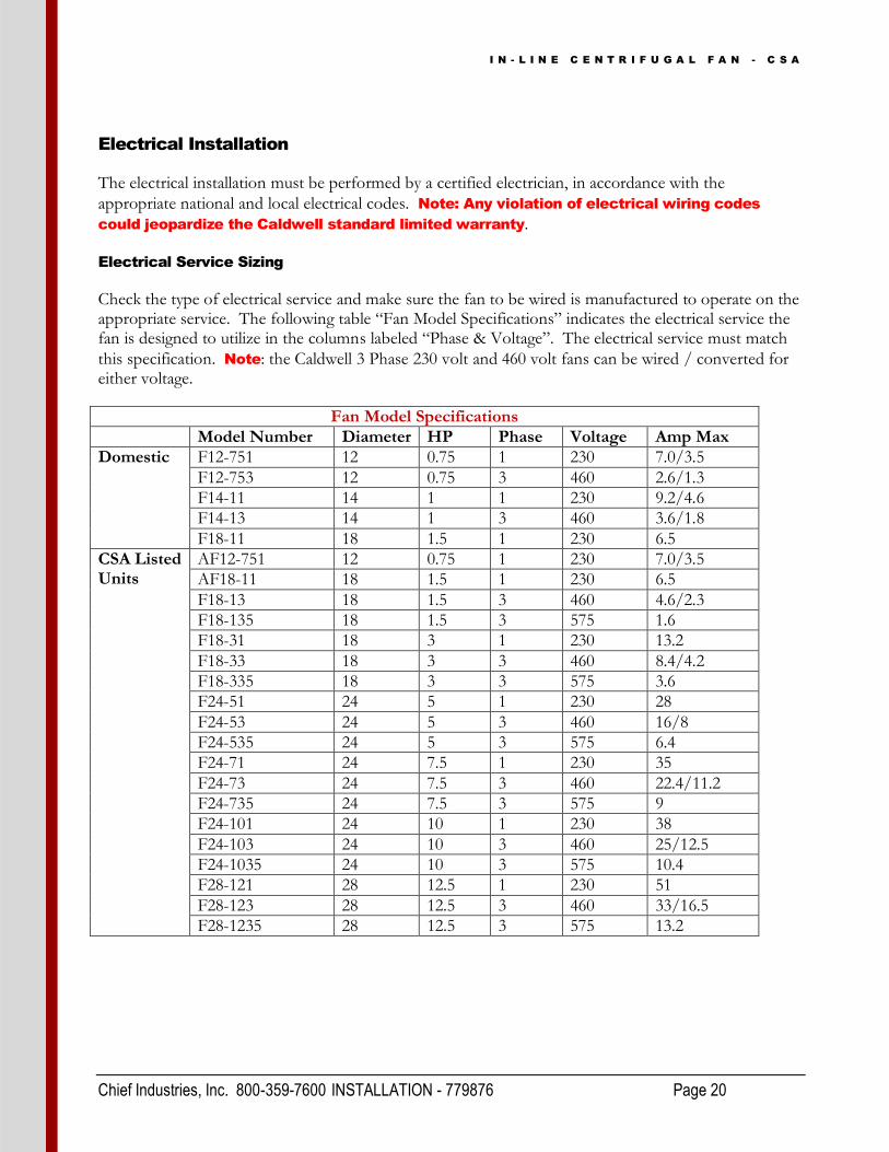
Check the type of electrical service and make sure the fan to be wired is manufactured to operate on the appropriate service. The following table “Fan Model Specifications” indicates the electrical service the fan is designed to utilize in the columns labeled “Phase & Voltage”. The electrical service must match
this specification. Note: the Caldwell 3 Phase 230 volt and 460 volt fans can be wired / converted for either voltage.
Fan Model Specifications
Model Number Diameter HP Phase Voltage Amp Max
Domestic F12-751 12 0.75 1 230 7.0/3.5
F12-753 12 0.75 3 460 2.6/1.3
F14-11 14 1 1 230 9.2/4.6
F14-13 14 1 3 460 3.6/1.8
F18-11 18 1.5 1 230 6.5
CSA Listed Units
AF12-751 12 0.75 1 230 7.0/3.5
AF18-11 18 1.5 1 230 6.5
F18-13 18 1.5 3 460 4.6/2.3
F18-135 18 1.5 3 575 1.6
F18-31 18 3 1 230 13.2
F18-33 18 3 3 460 8.4/4.2
F18-335 18 3 3 575 3.6
F24-51 24 5 1 230 28
F24-53 24 5 3 460 16/8
F24-535 24 5 3 575 6.4
F24-71 24 7.5 1 230 35
F24-73 24 7.5 3 460 22.4/11.2
F24-735 24 7.5 3 575 9
F24-101 24 10 1 230 38
F24-103 24 10 3 460 25/12.5
F24-1035 24 10 3 575 10.4
F28-121 28 12.5 1 230 51
F28-123 28 12.5 3 460 33/16.5
F28-1235 28 12.5 3 575 13.2

I N - L I N E C E N T R I F U G A L F A N - C S A
Chief Industries, Inc. 800-359-7600 INSTALLATION - 779876 Page 21
The components to connect the electrical service to the fan need to be sized for the electrical service present. The following tables illustrate the component sizing information for single phase 230 volt, 3 phase 230 volt and 3 phase 460 volt, and 3 phase 575 volt respectively.
Transformer size is based on current draw from the fan only. Your electrician will need to add the KVA
requirements for other components of the system in sizing the transformer.
Copper wire (rated 75°C) is sized for the fan service. The wire size from the transformer to the
disconnect service will be determined from the fan and the other electrical equipment requirements.
A disconnect for the fan needs to be sized to handle the recommended time delay fuse or circuit breaker
size.
Electrical Service For 1 Phase Operation 230 Volt
MOTOR H.P.
TRANSFORMER SIZE (NOTE B)
(MINIMUM)
COPPER WIRE SIZE DISTANCE MOTOR TO DISCONNECT IN FT. UP TO
TIME DELAY FUSE/BREAKER
AMP 0'-50' (15.2m)
100' (30.4m)
200' (60.9m)
300' (91.4m)
1.5 2.5 KVA 14 12 10 8 15
3 4.5 KVA 12 10 6 5 30
5 8.5 KVA 8 6 4 3 50
7.5 10.0 KVA 6 6 3 1 60
10 13.0 KVA 6 4 2 1/0 70
12.5 16.0 KVA 4 2 00 000 80
Electrical Service for 3 Phase Operation 230/460 Volt
MOTOR H.P.
TRANSFORMER SIZE (NOTE B)
(MINIMUM)
COPPER WIRE SIZE DISTANCE MOTOR TO DISCONNECT IN FT. UP TO
TIME DELAY FUSE/BREAKER
AMP
0'-50' (15.2m)
100' (30.4m)
200' (60.9m)
300' (91.4m) 230 460
230 460 230 460 230 460 230 460
1.5 2.5 KVA 14 14 14 14 12 14 10 12 10 5
3 4.5 KVA 14 14 12 14 10 12 8 10 15 8
5 8.5 KVA 12 14 10 12 6 10 4 8 30 15
7.5 10.0 KVA 10 14 8 12 6 8 4 6 40 20
10 13.0 KVA 10 12 8 10 4 8 2 6 50 25
12.5 16.0 KVA 8 12 6 10 2 6 1 4 60 30
Electrical Service for 3 Phase Operation 575 Volt
MOTOR H.P.
TRANSFORMER SIZE (NOTE B)
(MINIMUM)
COPPER WIRE SIZE DISTANCE MOTOR TO DISCONNECT IN FT. UP TO
TIME DELAY FUSE/BREAKER
AMP 0'-50' (15.2m)
100' (30.4m)
200' (60.9m)
300' (91.4m)
1.5 2.5 KVA 14 14 14 14 4
3 4.5 KVA 14 14 12 12 8
5 8.5 KVA 14 12 10 8 10
7.5 10.0 KVA 14 12 8 8 15
10 13.0 KVA 12 12 8 6 20
12.5 16.0 KVA 12 10 6 4 25
I N - L I N E C E N T R I F U G A L F A N - C S A
Chief Industries, Inc. 800-359-7600 INSTALLATION - 779876 Page 22
Electrical service examples:
1. Transformer example: For an F18-312 fan, the single phase 230 volt table would be used. The KVA
rating for the 3 horsepower motor is 4.5 KVA. This KVA rating is for the fan only. Your electrician
will need to add the KVA requirements for the other electrical components of the system in sizing the
transformer.
2. Fan disconnect example: For an F18-312 fan, the single phase 230 volt table would be used, and the fuse
/ breaker size is 30 amp. Note that a circuit breaker can be used, however, the circuit breaker or any
fuse used, must be a time delay type sized to allow for the initial starting in-rush current to the fan.
3. Conductor size example: The conductor size for the fan needs to be sized according to the distance
between the fan and disconnect. For an F18-312 fan located 200’ (60.9m) from the disconnect, the
single phase 230 volt table would be used. The conductor size should be #6 AWG. The proper sized
wiring must be used to make sure a voltage drop is not developed.
Electrical Connection at the Fan
1. Single Phase
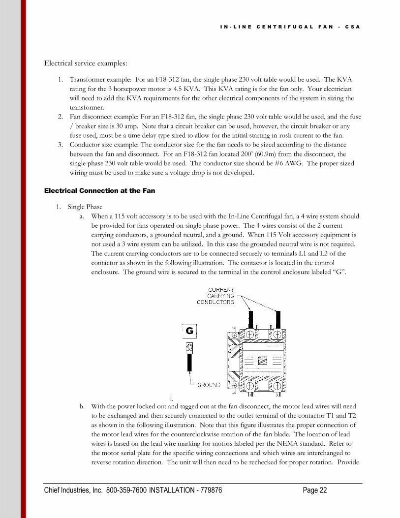
a. When a 115 volt accessory is to be used with the In-Line Centrifugal fan, a 4 wire system should
be provided for fans operated on single phase power. The 4 wires consist of the 2 current
carrying conductors, a grounded neutral, and a ground. When 115 Volt accessory equipment is
not used a 3 wire system can be utilized. In this case the grounded neutral wire is not required.
The current carrying conductors are to be connected securely to terminals L1 and L2 of the
contactor as shown in the following illustration. The contactor is located in the control
enclosure. The ground wire is secured to the terminal in the control enclosure labeled “G”.
i. b. With the power locked out and tagged out at the fan disconnect, the motor lead wires will need
to be exchanged and then securely connected to the outlet terminal of the contactor T1 and T2
as shown in the following illustration. Note that this figure illustrates the proper connection of
the motor lead wires for the counterclockwise rotation of the fan blade. The location of lead
wires is based on the lead wire marking for motors labeled per the NEMA standard. Refer to
the motor serial plate for the specific wiring connections and which wires are interchanged to
reverse rotation direction. The unit will then need to be rechecked for proper rotation. Provide

I N - L I N E C E N T R I F U G A L F A N - C S A
Chief Industries, Inc. 800-359-7600 INSTALLATION - 779876 Page 23
power to the fan controls and start the fan momentarily. Make sure that the blade rotation
develops airflow in the direction that the decal on the fan housing illustrates.
i. 2. 3 Phase
a. When a 115 volt accessory is to be used with the In-Line Centrifugal fan a 5 wire system should
be provided for fans operated on 3 phase 230 volt power. The 5 wires consist of 3 current
carrying conductors, a grounded neutral and a ground. When 115 volt accessory equipment is
not used, or the fan is operated on 460 volt 3 phase power or 575 volt 3 phase power, a 4 wire
system can be utilized. The 4 wires consist of 3 current carrying conductors and a ground. In
this case the grounded neutral wire is not required. The current carrying conductors are to be
connected securely to terminals L1, L2 and L3 of the contactor as shown in the following
illustration. The contactor is located in the control enclosure. The ground wire is secured to the
terminal in the control enclosure labeled “G”.
i. b. With the power locked out and tagged out at the fan disconnect, exchange the location of the
current carrying conductors at terminals L1 and L3 of the contactor as shown in the following
illustration. The unit will then need to be rechecked for proper rotation.

I N - L I N E C E N T R I F U G A L F A N - C S A
Chief Industries, Inc. 800-359-7600 INSTALLATION - 779876 Page 24
i. If the blade is rotating in the wrong direction correct as follows: Provide power to the
fan controls and start the fan momentarily. Make sure that the blade rotation develops
airflow in the direction that the decal on the fan housing illustrates.
1.

I N - L I N E C E N T R I F U G A L F A N - C S A
Chief Industries, Inc. 800-359-7600 INSTALLATION - 779876 Page 25
Wiring Schematics:
Please note the following wiring diagrams for installation:

I N - L I N E C E N T R I F U G A L F A N - C S A
Chief Industries, Inc. 800-359-7600 INSTALLATION - 779876 Page 26

I N - L I N E C E N T R I F U G A L F A N - C S A
Chief Industries, Inc. 800-359-7600 INSTALLATION - 779876 Page 27

I N - L I N E C E N T R I F U G A L F A N - C S A
Chief Industries, Inc. 800-359-7600 INSTALLATION - 779876 Page 28

I N - L I N E C E N T R I F U G A L F A N - C S A
Chief Industries, Inc. 800-359-7600 INSTALLATION - 779876 Page 29

I N - L I N E C E N T R I F U G A L F A N - C S A
Chief Industries, Inc. 800-359-7600 INSTALLATION - 779876 Page 30
Voltage Conversions:
1. Converting a 3 phase dual voltage fan wired for 230 volts to 460 volt service:
a. Make sure to lock out and tag out the power to the fan to ensure no power is present when
rewiring.
b. Disconnect the motor leads attached to the contactor terminals T1, T2 and T3. Break the
connection of the motor leads 4, 5 and 6 so that each motor lead is separate.

I N - L I N E C E N T R I F U G A L F A N - C S A
Chief Industries, Inc. 800-359-7600 INSTALLATION - 779876 Page 31
c. Remove the contactor from the control enclosure and disconnect the wires from the contactor
to the toggle switch and to the motor thermal protector. Disassemble the contactor.
d. The holding coil or complete contactor will need to be replaced. Refer to the conversion parts
table to order the correct 460 volt holding coil or contactor indicated for the fan model being
converted. Next reassemble the contactor with the new 460 volt contactor as shown in the
following illustration.
i. e. The contactor is then reinstalled into the control enclosure, and the toggle switch wires and the
motor thermal protection are re-wired per the corresponding 460 volt wiring diagram.
f. Connect the motor leads to the output terminal of the contactor as shown in the following
illustration. Note that the motor lead wire pairs (4 and 7), (5 and 8), (6 and 9) are secured
together using a wire nut.

I N - L I N E C E N T R I F U G A L F A N - C S A
Chief Industries, Inc. 800-359-7600 INSTALLATION - 779876 Page 32
g. Refer to the previous electrical service installation instructions for sizing the electrical service on
460 volt 3 phase operations.
2. Converting a 3 phase dual voltage fan wired for 460 volts to new 230 volt service:
a. Make sure to lock out and tag out the power to the fan to ensure no power is present when
rewiring.
b. Disconnect the motor leads attached to the contactor terminals T1, T2 and T3. Break each of
the paired motor lead connections (4 and 7), (5 and 8), and (6 and 9), so that each motor lead is
separate.
c. Remove the contactor from the control enclosure and disconnect the contactor from the toggle
switch and the motor thermal protector.
d. The holding coil or complete contactor will need to be replaced. Refer to the conversion parts
table to order the correct 230 volt holding coil or contactor indicated for the fan model being
converted. Next reassemble the contactor with the new 230 volt contactor as shown in the
following illustration.
I N - L I N E C E N T R I F U G A L F A N - C S A
Chief Industries, Inc. 800-359-7600 INSTALLATION - 779876 Page 33
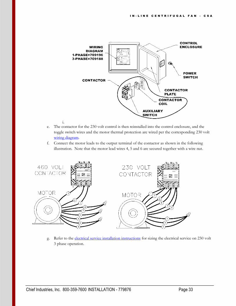
i. e. The contactor for the 230 volt control is then reinstalled into the control enclosure, and the
toggle switch wires and the motor thermal protection are wired per the corresponding 230 volt
wiring diagram.
f. Connect the motor leads to the output terminal of the contactor as shown in the following
illustration. Note that the motor lead wires 4, 5 and 6 are secured together with a wire nut.
g. Refer to the electrical service installation instructions for sizing the electrical service on 230 volt
3 phase operation.

I N - L I N E C E N T R I F U G A L F A N - C S A
Chief Industries, Inc. 800-359-7600 OPERATION - 779876 Page 34
Operating Instructions
When the fan is to be started for the first time, or after the fan has been idle for an extended period of time, the following checks should be made prior to starting the fan.
1. With the power locked out and tagged out at the disconnect switch, rotate the fan blade to make sure it revolves easily and does not rub on the housing.
2. Check all the fasteners to make sure they are tight. If any are loose, check for proper clearance and retighten fasteners. Make sure the screen guard is fastened securely.
3. With power locked out and tagged out at the disconnect switch, check all electrical connections to
make sure they are tight. Inspect the current carrying wires to make sure they are not grounded.
Make sure the control enclosure cover is secured in place.
4. Refer to the appropriate wiring diagram to verify the fan is wired correctly.
Start-Up Procedure:
The single phase 230 volt In-Line Centrifugal fans listed below use a permanent-split phase capacitor start motor. The start switch and start capacitors have been eliminated for trouble free operation. The permanent-split phase capacitor start motor is referred has a “slow start” motor because it comes up to speed much slower than a capacitor start single phase motor. When the fan is started, allow the motor
time to accelerate to full speed without turning the power off. Note: Do not continue short multiple starts as overheating of the motor could result.
1. 230/460 Voltage Fans
a. On 230 volt and 460 volt units, the fan is started by moving the toggle switch on the
control enclosure from the “OFF” position through the “RUN” position up to the
“START” position. When the fan begins to start the switch should be released. The
switch is designed to return to the “RUN” position. In this position the fan will
continue to operate until the toggle is moved from the “RUN” to the “OFF” position,
or unit the internal motor thermal protection interrupts the power by opening the
circuit. With the motor thermal protection in the open position the fan cannot be started
by moving the toggle into the “START” position. When the motor thermal protector
Fan Model Time to Start F12-751 5 Seconds F14-11 8 Seconds F18-112 8 Seconds F18-312 8 Seconds F24-512 8 Seconds F24-712 10 Seconds F24-1012 10 Seconds
F28-1212 16 Seconds

I N - L I N E C E N T R I F U G A L F A N - C S A
Chief Industries, Inc. 800-359-7600 OPERATION - 779876 Page 35
closes, the fan will not restart by itself, the toggle will need to be moved to the
“START” position to start the unit again. Note: If the motor thermal protector
activates to shut off the fan refer to the service section for determining the cause of the
thermal protector activating.
2. 575 Voltage Fans
a. On 575 volt units, the fan is started by pushing in the switch button on the control
enclosure marked “START”. When the fan begins to start the button should be
released. The fan will continue to operate until the “STOP” button is pushed in, or until
the internal motor thermal protection interrupts the power by opening the circuit. With
the motor thermal protection in the open position the fan cannot be started by pushing
the “START” button in. When the motor thermal protector closes, the fan will not
restart by itself, the “START” button will need to be pushed in to start the unit again.
Note: If the motor thermal protector activates to shut off the fan refer to the service
section for determining the cause of the thermal protector activating.
Shut-Down Procedure:
1. When shutting the fan down for the season, shut off the power at the fan disconnect rather than at the
fan controls to provide additional protection from unauthorized personnel operating the fan, and
potential damage to the fan from a lightning strike. Refer to the maintenance section for off season
operation recommendations.
Maintenance
The following procedures should be followed and maintenance performed before starting the unit at the beginning of every season, and also during operation.
Off Season Operation:
During the off season, the fan blade should be allowed to turn freely. Also, during the off season, operate the fan for approximately 30 minutes every 3 weeks. The operation of the fan keeps the lubricant evenly distributed within the bearing cavity and removes condensation from the motor.
Fan Controls:
During the off season, make sure the control enclosure cover is secured to the control enclosure. Before operating, the magnetic contactor should be inspected to make sure all contact points are clean and unobstructed. Also, check points for pitting and replace the magnetic contactor if the points are defective.

I N - L I N E C E N T R I F U G A L F A N - C S A
Chief Industries, Inc. 800-359-7600 MAINTAINENCE - 779876 Page 36
Fan Motor:
The life span of the motor is dependent on proper bearing maintenance. Before lubricating the bearings, inspect the bearings to make sure they are still in good condition. If not, the bearings will need to be replaced. The fan motor uses sealed bearings, however, the bearing cavity should still be lubricated. The motor should be lubricated once a year prior to the operating season per the following
instructions. Note: The lubricants listed below are designed to operate at high temperature and have a rust inhibitor for extended bearing life. Do not mix other grease types with these lubricants. In addition do not over lubricate the bearings as the lubricant will work its way into the motor and cause premature motor failure.
To lubricate a motor with filler and drain holes, remove both plugs and clean the holes of any hardened
lubricants. Approximately three standard pumps of Shell Dolium R or Chevron SRI-2 lubricant should
be added. Allow the motor to run for approximately 10 minutes before reinstalling the drain plug.
To lubricate a motor without filler and drain holes, first clean out any hardened grease, and then add the
Shell Dolium R or Chevron SRI-2 lubricant to fill ¾ of the cavity of the end bell.
Fan Blades:
Clean the fan blade so the unit runs smoothly. This should be done once per year or as needed if vibration develops. Also check the fan to make sure it is mounted properly. Refer to the previous installation instructions for instructions on leveling the fan.
If, in servicing the fan, you determine that the fan blade will need to be removed from the motor shaft, refer to the following instructions to make sure the reassembled fan will perform properly.
When reassembling the fan blade on the motor shaft verify the blade is centered in the fan housing.
Shim motor to center the fan blade if required.
When tightening the tapered bushing hardware, tighten the bolts gradually by continually working in a
circle turning each fastener slightly. Finally, torque the bolts to the following specifications:
o F12 = 60 lb (27.21 kg)
o F14 = 60 lb (27.12 kg)
o F18-1 = 80 lb (36.28 kg)
o F18-3 = 100 lb (45.35 kg)
o F24 = 100 lb (45.35 kg)
o F28 = 100 lb (45.35 kg)
Servicing the Fan:
The following will help you find any problems that may occur in the fan unit and includes tips for repair. For servicing of electrical systems, open the control box cover. Inside the cover you will find a wiring schematic to help you service the unit. In the checks shown below, locate the symptoms you are experiencing with your unit and follow the list of corresponding possible causes and remedies:

I N - L I N E C E N T R I F U G A L F A N - C S A
Chief Industries, Inc. 800-359-7600 MAINTAINENCE - 779876 Page 37
Note: Unless otherwise indicated, checks are made with the power off using a voltmeter on resistance setting.
Condition Specific Faults:
1. Symptom: Toggle switch does not turn fan on.
a. Verify power is available to the fan unit.
b. Check overload protection to determine if the control circuit is open or closed.
i. If the thermostat is open, verify the overload device has had a chance to cool if
the fan has recently shut off. The overload circuit will automatically close when
the unit is cooled. If not, the thermostat will need to be replaced in the motor.
1. The thermostat wires (J wires) can be traced from the motor to terminal
L1 and the toggle switch.
c. Check the toggle switch. If switch is defective, replace.
i. The toggle switch circuit should be checked in the “OFF”, “RUN”, and
“START” positions. The top left side and top right side of the toggle switch
should be metered to the bottom of the toggle switch to determine if the circuit
is open or closed.
1. In the “OFF” position, both sides should be open.
2. In the “RUN” position, the left side should be closed and the right side
should be open.
3. With the toggle switch held in the “START” position, both sides should
be closed.
d. Check holding coil. If coil is defective, replace.
i. Verify power from L2 on the contactor to the holding coil.
ii. Verify power going from L1 through the motor thermostat wires and the toggle
switch. If power is available at the coil, the coil is defective.
e. Verify that the contact set is not restricted from closing.
2. Symptom: Fan motor hums and does not run.
a. Check to make sure that all leads of your power source have voltage present. If fan unit
is not receiving power on all leads, check for a blown fuse, broken wire, or loose
connection.
b. Check to see that all contact sets are closing. If one leg of the supply voltage is not
available to the motor, the motor will hum.
i. Remove the front cover from the contactor, turn the fan unit on and watch to
see that all contacts close. If all contacts do not close, clean or replace contactor.
c. If power is available at all the motor leads and the motor still hums, then the motor
should be taken to an authorized Service Center for repair or replacement.
i. The power can be hooked directly to the motor leads (for testing), if the motor
hums, replace or repair the motor.

I N - L I N E C E N T R I F U G A L F A N - C S A
Chief Industries, Inc. 800-359-7600 MAINTAINENCE - 779876 Page 38
3. Symptom: Fan operates when the toggle switch is held in the “START” position but shuts off
when the toggle switch is in the “RUN” position.
a. Check steps referenced above in Symptom “Toggle switch does not turn fan on”.
b. Check the auxiliary switch; locate on the side of the contactor. (If defective, replace
auxiliary switch. Refer to “replacement parts” to determine the part required.
i. With the power supply OFF remove the front plate from the contactor and
verify the auxiliary switch is open. Switch should close when the contact sets are
pushed in. Circuit is checked by measuring the resistance across the auxiliary
switch.
4. Symptom: Fan only operates at half speed.
a. Take the motor to an authorized service center for repair or replacement.
5. Symptom: Fan Starts and operates for brief period of time than shuts off.
a. Check the supply voltage. Voltage should be within 10% of rated voltage. For example,
a motor rated at 230 volts should operate in a voltage range of 207 to 253 Volts.
b. Check the supply wire sizes required for the fan unit.
c. Check the load on the main circuit to make sure other items on the main circuit are not
overloading the fan circuit.
d. Check the amperage of the fan, if the unit is pulling amperage above what is specified on
the serial plate; take the motor to an Authorized Service Center.
6. Symptom: Fan operates when main power supply is turned on.
a. The top two terminals of the toggle switch should be checked. If the circuit is closed
between the two terminals, the toggle switch should be replaced.
b. Check the contact points by removing the front from the contactor to see if the contacts
are locked in or welded in place. If so, the complete contactor should be replaced.

I N - L I N E C E N T R I F U G A L F A N - C S A
Chief Industries, Inc. 800-359-7600 WARRANTY - 779876 Page 39

I N - L I N E C E N T R I F U G A L F A N - C S A
Chief Industries, Inc. 800-359-7600 WARRANTY - 779876 Page 40
STANDARD LIMITED WARRANTY
Caldwell Aeration Products 1. Definitions. The following terms, when they appear in the body of this Standard Limited
Warranty for Caldwell Aeration Products in initial capital letters shall have the meaning set forth below: A. Accepted Purchase Order shall mean the Purchase Order identified below. B. Chief shall mean Chief Agri/Industrial, a division of Chief Industries, Inc. C. Original Owner shall mean the original owner identified below. D. Product shall mean the Agri/Industrial Equipment as described in the Accepted
Purchase Order. E. Reseller shall mean the authorized Chief Agri/Industrial Equipment dealer identified
below. 2. Limited Product Warranty. Upon and subject to the terms and conditions set forth below,
Chief hereby warrants to the Reseller, and, if different, the Original Owner as follows: A. All new Products delivered to the Reseller or the Original Owner by Chief pursuant to
the Accepted Purchase Order will, when delivered, conform to the specifications set forth in the Accepted Purchase Order;
B. All new Products delivered pursuant to the Accepted Purchase Order will, in normal use and service, be free from defects in materials or workmanship; and
C. Upon delivery, Chief will convey good and marketable title to the Products, free and clear of any liens or encumbrances except for, where applicable, a purchase money security interest in favor of Chief.
3. Duration of Warranty and Notice Requirements. Subject to the Exceptions, Exclusions
and Limitations set forth below, the warranties set forth in Section 2 above shall apply to all covered non-conforming conditions that are discovered within the first twenty-four (24) months following delivery of the Product to the carrier designated by the Reseller and/or the Original Owner at Chief’s manufacturing facility in Kearney, Nebraska (the “Warranty Period”) and are reported to the Chief as provided in Section 4 below within thirty (30) days following discovery (a “Notice Period”).
4. Notice Procedure. In order to make a valid warranty claim, the Reseller and/or the Original
Owner must provide Chief with a written notice of any nonconforming condition discovered during the Warranty Period within the applicable Notice Period specified in Section 3 above. Said notice must be in writing; be addressed to Chief Industries, Inc., Agri/Industrial Division, Customer Service Department, P.O. Box 848, Kearney, NE 68848; and contain the following information: (a) the Customer’s name and address; (b) the Reseller’s name and address; (c) the make and model of the Product in question; (d) the current location of the Product; (e) a brief description of the problem with respect to which warranty coverage is claimed; and (f) the date on which the Product was purchased.

I N - L I N E C E N T R I F U G A L F A N - C S A
Chief Industries, Inc. 800-359-7600 WARRANTY - 779876 Page 41
5. Exceptions and Exclusions. Anything herein to the contrary notwithstanding, the warranties set forth in Section 2 above do not cover any of the following, each of which are hereby expressly excluded: A. Defects that are not discovered during the applicable Warranty Period; B. Defects that are not reported to the Chief Agri/Industrial Division Customer Service
Department in conformity with the notice procedure set forth in Section 4 above within the applicable Notice Period specified in Section 3;
C. Any used or pre-owned Products; D. Any Chief manufactured parts that are not furnished as a part of the Accepted Purchase
Order; E. Any fixtures, equipment, materials, supplies, accessories, parts or components that have
been furnished by Chief but are manufactured by a third party; F. Any Products which have been removed from the location at which they were originally
installed; G. Any defect, loss, damage, cost or expense incurred by the Reseller or the Original
Owner to the extent the same arise out of, relate to or result, in whole or in part, from any one or more of the following: (i) Usual and customary deterioration, wear or tear resulting from normal use,
service and exposure; (ii) Theft, vandalism, accident, war, insurrection, fire or other casualty; (iii) Any damage, shortages or missing parts which result during shipping or are
otherwise caused by the Reseller, the Original Owner and/or any third party; (iv) Exposure to marine environments, including frequent or sustained salt or fresh
water spray; (v) Exposure to corrosive, chemical, ash, smoke, fumes, or the like generated or
released either within or outside of the structure on which the Product is installed, regardless of whether or not such facilities are owned or operated by the Reseller, the Original Owner or an unrelated third party;
(vi) Exposure to or contact with animals, animal waste and/or decomposition; (vii) The effect or influence the Product may have on surrounding structures,
including, without limitation, any loss, damage or expense caused by drifting snow;
(viii) Any Product or portion thereof that has been altered, modified or repaired by the Reseller, the Original Owner or any third party without Chief’s prior written consent;
(ix) Any Product or portion thereof that has been attached to any adjacent structure without Chief’s prior written approval;
(x) Any Product to which any fixtures, equipment, accessories, materials, parts or components which were not provided as a part of the original Accepted Purchase Order have been attached without Chief’s prior written approval;
(xi) The failure on the part of the Reseller, the Original Owner or its or their third party contractors to satisfy the requirements of all applicable statutes, laws, ordinances rules, regulations and codes, (including zoning laws and/or building codes);
(xii) The use of the Product for any purpose other than the purpose for which it was designed; and/or

I N - L I N E C E N T R I F U G A L F A N - C S A
Chief Industries, Inc. 800-359-7600 WARRANTY - 779876 Page 42
(xiii) The failure of the Reseller, the Original Owner and/or any third party to: (a) properly handle, transport and/or store the Product or any component
part thereof; (b) properly select and prepare a site that is adequate for the installation
and/or operation of the Product or any component part thereof; (c) properly design and construct a foundation that is adequate for the
installation and/or operation of the Product or any component part thereof;
(d) properly set up, erect, construct or install the Product and/or any component part thereof; and/or
(e) properly operate, use, service and/or maintain the Product and each component part thereof.
6. Resolution of Warranty Claims. In the event any nonconforming condition is discovered
within the Warranty Period and Chief is notified of a warranty claim as required by Section 4 prior to the end of the applicable Notice Period set forth in Section 3 above, Chief shall, with the full cooperation of the Reseller and the Original Owner, immediately undertake an investigation of such claim. To the extent Chief shall determine, in its reasonable discretion, that the warranty claim is covered by the foregoing Limited Product Warranty, the following shall apply: A. Warranty Claims With Respect to Covered Non-Conforming Conditions Discovered
Within the First Three Hundred Sixty Five (365) Days and Reported to Chief Within Thirty (30) Days of Discovery. In the case of a warranty claim which relates to a covered non-conforming condition that is discovered during the first three hundred sixty five (365) days of the Warranty Period and is reported to Chief as required by Section 4 within thirty (30) days of discovery as required by Section 3, Chief will, as Chief’s sole and exclusive obligation to the Reseller and the Original Owner, and as their sole and exclusive remedy, work in cooperation with the Reseller and the Original Owner to correct such non-conforming condition, and in connection therewith, Chief will ship any required replacement parts to the “ship to address” set forth in the Accepted Purchase Order FOB Chief’s facilities in Kearney, Nebraska, and will either provide the labor or reimburse the Reseller or the Original Owner, as may be appropriate in the circumstances, for any out of pocket expense the Original Owner may reasonably and necessarily incur for the labor that is required to correct such non-conforming condition, provided that if work is to be performed by the Reseller or a third party contractor, Chief may require at least two competitive bids to perform the labor required to repair or correct the defect and reserves the right to reject all bids and obtain additional bids. Upon acceptance of a bid by Chief, Chief will authorize the necessary repairs.
B. All Other Warranty Claims. Except as is otherwise provided in subsection 6A above, in the case of all other warranty claims which relate to covered non-conforming conditions that are discovered during the Warranty Period and are reported to Chief as required by Section 4 within thirty (30) days following discovery, Chief will, as Chief’s sole and exclusive obligation to the Reseller and the Original Owner, and as the Reseller’s and the Original Owner’s sole and exclusive remedy, ship any required replacement parts to the Original Owner at the “ship to address” specified in the Accepted Purchase Order FOB

I N - L I N E C E N T R I F U G A L F A N - C S A
Chief Industries, Inc. 800-359-7600 WARRANTY - 779876 Page 43
Chief’s facilities in Kearney, Nebraska; and in such event, Chief shall have no responsibility or liability to either the Reseller or the Original Owner for the cost of any labor required to repair or correct the defect.
7. Warranty Not Transferable. This Warranty applies only to the Reseller and the Original
Owner and is not transferable. As such, this Warranty does not cover any Product that is sold or otherwise transferred to any third party following its delivery to the Original Owner.
8. Limitation on Warranties, Liabilities and Damages. The Reseller and the Original Owner
expressly agree that the allocation of the risk, liability, loss, damage, cost and expense arising from any Product that does not conform to the limited warranty given in Section 2 above are fair and reasonable and acknowledge that such allocation was expressly negotiated by the parties and was reflected in the Purchase Price of the Product. Accordingly the Reseller and the Original Owner expressly agree as follows: A. Disclaimer of Implied Warranties. EXCEPT AS IS OTHERWISE EXPRESSLY
SET FORTH HEREIN, CHIEF MAKES NO OTHER REPRESENTATIONS OR WARRANTIES OF ANY KIND WHATSOEVER, WHETHER EXPRESS OR IMPLIED, BY OPERATION OF LAW, COURSE OF DEALING OR OTHERWISE WITH RESPECT TO THE PRODUCT, ANY COMPONENT PART THEREOF OR ANY OTHER GOODS OR SERVICES THAT CHIEF MANUFACTURES, FABRICATES, PRODUCES, SELLS OR PROVIDES TO THE DEALER OR THE ORIGINAL OWNER PURSUANT TO THE TERMS OF ANY ACCEPTED PURCHASE ORDER, INCLUDING WITHOUT LIMITATION ANY REPRESENTATION OR WARRANTY WITH RESPECT TO DESIGN, CONDITION, MERCHANTABILITY OR FITNESS OF THE PRODUCT OR ANY OTHER GOODS OR SERVICES FOR ANY PARTICULAR PURPOSE OR USE.
B. Limitation on Liability. EXCEPT AS IS OTHERWISE EXPRESSLY SET FORTH IN SECTION 6 ABOVE, CHIEF'S LIABILITY TO THE DEALER AND/OR THE ORIGINAL OWNER WITH RESPECT TO ANY DEFECTS IN ANY PRODUCTS OR FOR ANY OTHER GOODS OR SERVICES WHICH DO NOT CONFORM TO THE WARRANTIES SET FORTH ABOVE SHALL NOT, IN ANY EVENT, EXCEED THE ACTUAL COST OF SUCH NON-CONFORMING PRODUCT, GOODS OR SERVICES AS DETERMINED PURSUANT TO THE ACCEPTED PURCHASE ORDER; AND
C. Limitation on the Nature of Damages. EXCEPT AS EXPRESSLY PROVIDED IN SECTION 6 ABOVE, CHIEF SHALL NOT, UNDER ANY CIRCUMSTANCES, BE LIABLE TO THE DEALER, THE ORIGINAL OWNER OR ANY THIRD PARTY FOR ATTORNEY FEES COURT COSTS OR ANY OTHER SPECIAL, INDIRECT, INCIDENTAL, CONSEQUENTIAL, LIQUIDATED OR PUNITIVE DAMAGES OF ANY NAME, NATURE OR DESCRIPTION AS A RESULT OF THE FAILURE OF ANY PRODUCT OR ANY OTHER GOODS OR SERVICES PURCHASED BY THE DEALER OR THE ORIGINAL OWNER FROM CHIEF PURSUANT

I N - L I N E C E N T R I F U G A L F A N - C S A
Chief Industries, Inc. 800-359-7600 WARRANTY - 779876 Page 44
TO THE ACCEPTED PURCHASE ORDER TO CONFORM TO THE LIMITED WARRANTIES SET FORTH IN SECTION 2 ABOVE.
8. Applicable Law. This Limited Product Warranty has been issued, accepted and entered into by
the Reseller, the Original Owner and Chief in the State of Nebraska and shall be governed by, and construed in accordance with, the internal laws of the State of Nebraska. Any legal action or proceeding with respect to any goods or services furnished to the Original Owner by Chief in connection herewith, or any document related hereto shall be brought only in the district courts of Nebraska, or the United States District Court for the District of Nebraska, and, by execution and delivery of this Limited Product Warranty, the undersigned Original Owner hereby accept for themselves and with respect to their property, generally and unconditionally, the jurisdiction of the aforesaid courts. Further, the undersigned Original Owner hereby irrevocably waives any objection, including, without limitation, any forum non conveniens, which it may now or hereafter have to the bringing of such action or proceeding in such respective jurisdictions.
ACKNOWLEDGMENT OF RECEIPT
By its signature hereto, the undersigned Reseller represents and warrants to Chief that the Reseller has provided a true, correct and complete copy of this Standard Limited Warranty to the Original Owner at the time the product was purchased. Reseller Name and Address: _______________________________ _______________________________ _______________________________ Original Owner Name and Address: _______________________________ _______________________________ _______________________________ Accepted Purchase Order No. _________________________ Original Jobsite Address: _____________________________________ _____________________________________ _____________________________________ RESELLER: By: _________________________________ Date Print name and title 4821-6088-7329, v. 1

I N - L I N E C E N T R I F U G A L F A N - C S A
Chief Industries, Inc. 800-359-7600 MANUAL - 779876 Page 45
Should you have any questions concerning assembly instructions, parts or drawings, please feel free to contact us at any of the following.
Chief Industries, Inc. Inc. 4400 East 39th Street • PO Box 848
Kearney, NE 68847 Phone 800.359.7600
For more information about Chief Industries, Inc. and additional products or services visit our website www.agri.chiefind.com
Model Number
ILC18
ILC24
ILC28