In-flight Investigation of a Rotating Cylinder-Based Structural Excitation System ... · ·...
26
NASA Technical Memorandum 4512 /N In-flight Investigation of a Rotating Cylinder-Based Structural Excitation System for Flutter Testing Lura Vernon June 1993 r (NASA-TM-4512) IN-FLIGHT " INVESTIGATION OF A ROTATING CYLINDER-BASED STRUCTURAL EXCITATION SYSTEM FOR FLUTTER TESTING (NASA) 22 p N94-15783 Uncl as Hi/05 0190899 https://ntrs.nasa.gov/search.jsp?R=19940011310 2018-06-01T05:43:05+00:00Z
Transcript of In-flight Investigation of a Rotating Cylinder-Based Structural Excitation System ... · ·...
NASA Technical Memorandum 4512
/N
In-flight Investigation of a
Rotating Cylinder-BasedStructural Excitation System
for Flutter Testing
Lura Vernon
June 1993
r (NASA-TM-4512) IN-FLIGHT" INVESTIGATION OF A ROTATING
CYLINDER-BASED STRUCTURAL
EXCITATION SYSTEM FOR FLUTTER
TESTING (NASA) 22 p
N94-15783
Uncl as
Hi/05 0190899
https://ntrs.nasa.gov/search.jsp?R=19940011310 2018-06-01T05:43:05+00:00Z

NASA Technical Memorandum 4512
In-flight Investigation of aRotating Cylinder-BasedStructural Excitation System
for Flutter Testing
Lura Vernon
Dryden Flight Research Facility
Edwards, California
National Aeronautics and
Space Administration
Office of Management
Scientific and TechnicalInformation Program
1993

IN-FLIGHT INVESTIGATION OF A ROTATING
CYLINDER-BASED STRUCTURAL EXCITATION SYSTEM
FOR FLUTTER TESTING
• Lura Vernon*
NASA Dryden Flight Research FacilityP.O. Box 273
Edwards, California 93523-0273
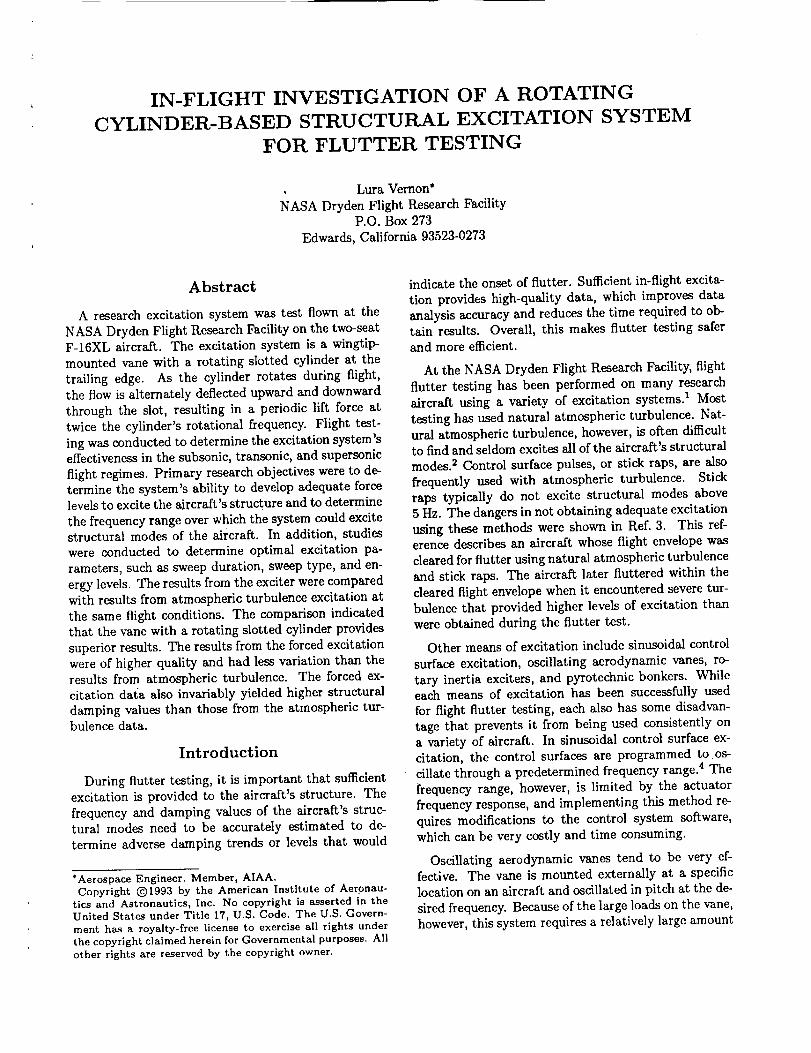
Abstract
A research excitation system was test flown at the
NASA Dryden Flight Research Facility on the two-seatF-16XL aircraft. The excitation system is a wingtip-
mounted vane with a rotating slotted cylinder at the
trailing edge. As the cylinder rotates during flight,
the flow is alternately deflected upward and downward
through the slot, resulting in a periodic lift force at
twice the cylinder's rotational frequency. Flight test-
ing was conducted to determine the excitation system'seffectiveness in the subsonic, transonic, and supersonic
flight regimes. Primary research objectives were to de-termine the system's ability to develop adequate forcelevels to excite the aircraft's structure and to determine
the frequency range over which the system could excite
structural modes of the aircraft. In addition, studieswere conducted to determine optimal excitation pa-
rameters, such as sweep duration, sweep type, and en-
ergy levels. The results from the exciter were comparedwith results from atmospheric turbulence excitation at
the same flight conditions. The comparison indicatedthat the vane with a rotating slotted cylinder provides
superior results. The results from the forced excitation
were of higher quality and had less variation than theresults from atmospheric turbulence. The forced ex-
citation data also invariably yielded higher structural
damping values than those from the atmospheric tur-bulence data.
Introduction
During flutter testing, it is important that sufficientexcitation is provided to the aircraft's structure. The
frequency and damping values of the aircraft's struc-tural modes need to be accurately estimated to de-
termine adverse damping trends or levels that would
*Aerospace Engineer. Member, AIAA.
Copyright (_)1993 by the American Institute of Aeronau-
tics and Astronautics, Inc. No copyright is asserted in the
United States under Title 17, U.S. Code. The U.S. Govern-
ment has a royalty-free license to exercise all rights under
the copyright claimed herein for Governmental purposes. All
other rights are reserved by the copyright owner.
indicate the onset of flutter. Sufficient in-flight excita-
tion provides high-quality data, which improves data
analysis accuracy and reduces the time required to ob-tain results. Overall, this makes flutter testing safer
and more efficient.
At the NASA Dryden Flight Research Facility, flight
flutter testing has been performed on many research
aircraft using a variety of excitation systems. 1 Most
testing has used natural atmospheric turbulence. Nat-
ural atmospheric turbulence, however, is often difficultto find and seldom excites all of the aircraft's structuralmodes. 2 Control surface pulses, or stick raps, are also
frequently used with atmospheric turbulence. Stick
raps typically do not excite structural modes above
5 Hz. The dangers in not obtaining adequate excitation
using these methods were shown in Ref. 3. This ref-erence describes an aircraft whose flight envelope was
cleared for flutter using natural atmospheric turbulence
and stick raps. The aircraft later fluttered within the
cleared flight envelope when it encountered severe tur-bulence that provided higher levels of excitation than
were obtained during the flutter test.
Other means of excitation include sinusoidal control
surface excitation, oscillating aerodynamic vanes, ro-
tary inertia exciters, and pyrotechnic bonkers. Whileeach means of excitation has been successfully used
for flight flutter testing, each also has some disadvan-
tage that prevents it from being used consistently on
a variety of aircraft. In sinusoidal control surface ex-citation, the control surfaces are programmed to os-
cillate through a predetermined frequency range) The
frequency range, however, is limited by the actuatorfrequency response, and implementing this method re-
quires modifications to the control system software,
which can be very costly and time consuming.
Oscillating aerodynamic vanes tend to be very ef-fective. The vane is mounted externally at a specific
location on an aircraft and oscillated in pitch at the de-
sired frequency. Because of the large loads on the vane,
however, this system requires a relatively large amount
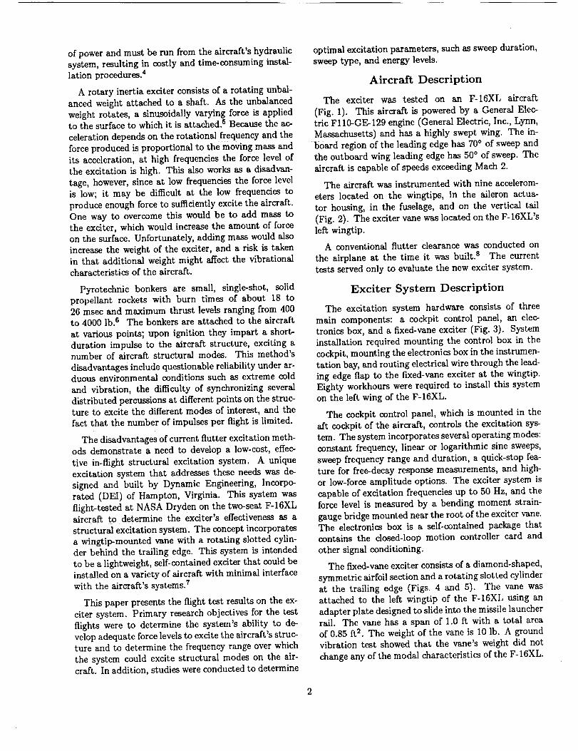
ofpowerandmustberunfromtheaircraft'shydraulicsystem,resulting in costly and time-consuming instal-
lation procedures. 4
A rotary inertia exciter consists of a rotating unbal-
anced weight attached to a shaft. As the unbalanced
weight rotates, a sinusoidally varying force is appliedto the surface to which it is attached. _ Because the ac-
celeration depends on the rotational frequency and the
force produced is proportional to the moving mass andits acceleration, at high frequencies the force level of
the excitation is high. This also works as a disadvan-
tage, however, since at low frequencies the force levelis low; it may be difficult at the low frequencies to
produce enough force to sufficiently excite the aircraft.
One way to overcome this would be to add mass tothe exciter, which would increase the amount of forceon the surface. Unfortunately, adding mass would also
increase the weight of the exciter, and a risk is taken
in that additional weight might affect the vibrational
characteristics of the aircraft.
Pyrotechnic bonkers are small, single-shot, solid
propellant rockets with burn times of about 18 to26 msec and maximum thrust levels ranging from 400
to 4000 lb. 8 The bonkers are attached to the aircraft
at various points; upon ignition they impart a short-
duration impulse to the aircraft structure, exciting anumber of aircraft structural modes. This method's
disadvantages include questionable reliability under ar-duous environmental conditions such as extreme cold
and vibration, the difficulty of synchronizing several
distributed percussions at different points on the struc-ture to excite the different modes of interest, and thefact that the number of impulses per flight is limited.
The disadvantages of current flutter excitation meth-ods demonstrate a need to develop a low-cost, effec-
tive in-flight structural excitation system. A unique
excitation system that addresses these needs was de-
signed and built by Dynamic Engineering, Incorpo-
rated (DEI) of Hampton, Virginia. This system was
flight-tested at NASA Dryden on the two-seat F-16XL
aircraft to determine the exciter's effectiveness as astructural excitation system. The concept incorporates
a wingtip-mounted vane with a rotating slotted cylin-der behind the trailing edge. This system is intended
to be a lightweight, self-contained exciter that could beinstalled on a variety of aircraft with minimal interface
with the aircraft's systems, v
This paper presents the flight test results on the ex-
citer system. Primary research objectives for the test
flights were to determine the system's ability to de-velop adequate force levels to excite the aircraft's struc-ture and to determine the frequency range over which
the system could excite structural modes on the air-craft. In addition, studies were conducted to determine
optimal excitation parameters, such as sweep duration,
sweep type, and energy levels.
Aircraft Description
The exciter was tested on an F-16XL aircraft
(Fig. 1). This aircraft is powered by a General Elec-tric Fl10-GE-129 engine (General Electric, Inc., Lynn,
Massachusetts) and has a highly swept wing. The in-
board region of the leading edge has 70° of sweep and
the outboard wing leading edge has 50 ° of sweep. The
aircraft is capable of speeds exceeding Mach 2.
The aircraft was instrumented with nine accelerom-
eters located on the wingtips, in the aileron actua-
tor housing, in the fuselage, and on the vertical tail
(Fig. 2). The exciter vane was located on the F-16XL's
left wingtip.
A conventional flutter clearance was conducted on
the airplane at the time it was built, s The current
tests served only to evaluate the new exciter system.
Exciter System Description
The excitation system hardware consists of three
main components: a cockpit control panel, an elec-
tronics box, and a fixed-vane exciter (Fig. 3). System
installation required mounting the control box in the
cockpit, mounting the electronics box in the instrumen-
tation bay, and routing electrical wire through the lead-
ing edge flap to the fixed-vane exciter at the wingtip.Eighty workhours were required to install this system
on the left wing of the F-16XL.
The cockpit control panel, which is mounted in the
aft cockpit of the aircraft, controls the excitation sys-
tem. The system incorporates several operating modes:constant frequency, linear or logarithmic sine sweeps,
sweep frequency range and duration, a quick-stop fea-ture for free-decay response measurements, and high-
or low-force amplitude options. The exciter system is
capable of excitation frequencies up to 50 Hz, and the
force level is measured by a bending moment strain-
gauge bridge mounted near the root of the exciter vane.The electronics box is a self-contained package that
contains the closed-loop motion controller card and
other signal conditioning.
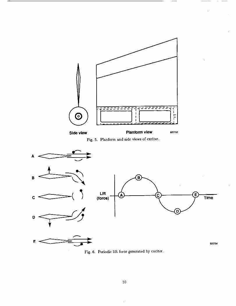
The fixed-vane exciter consists of a diamond-shaped,
symmetric airfoil section and a rotating slotted cylinder
at the trailing edge (Figs. 4 and 5). The vane wasattached to the left wingtip of the F-16XL using an
adapter plate designed to slide into the missile launcherrail. The vane has a span of 1.0 ft with a total area
of 0.85 ft2. The weight of the vane is 10 lb. A groundvibration test showed that the vane's weight did not
change any of the modal characteristics of the F-16XL.
Thetwoslotscut in thecylindergenerateperiodiclifting forcesthat excitetheaircraft.Asthecylinderrotatesduringflight,the flowis alternatelydeflectedupwardanddownwardthroughtheslots,resultingina periodiclift forceat twicethecylinder'srotationalfrequency.Figure6illustratesthis. PointA showsthezeroforceposition,pointB is themaximumpositiveforceposition,pointCiszeroforceagain,andpointDisthemaximumnegativeforceposition.Notethatthecylinderhasonlyrotated180° for one full sinusoidalforcing period. The amplitude of the excitation force
depends upon the dynamic pressure and the amount of
the slot opening.
The amount of slot opening is controlled by the direc-tion of rotation of the slotted cylinder. Reversing the
rotational direction of the cylinder drive motor causes
half of the spanwise slot opening to be blocked by an
inner cylinder in the inboard slot. Closing the inboardslot attenuates the excitation force by half in flight. In
addition, a plug was added to the outboard slot by themanufacturer after wind-tunnel tests indicated that the
vane may produce more force than is desirable at high
dynamic pressures. This plug spans 25 percent of theslot opening and reduces the amount of force that the
excitation system can provide. With this plug, when
the exciter is in the high-force mode, the slotted cylin-
der is 75 percent open (Fig. 7(a)). When the exciter isin the low-force mode, the slotted cylinder is 25 percent
open (Fig. 7(5)).
The lift force produced by the vane-rotating cylinder
concept is analogous to that of an oscillating vane. The
rotating cylinder's main advantage is that it requiresonly the relatively small amount of power needed toovercome the aerodynamic and frictional forces oppos-
ing its rotation. Therefore, a low-wattage electric servomotor is used to run the system. Requiring only 28 V,
the system can be readily integrated with an aircraft's
normal power supply.
The design condition for the vane is Mach 1.2 at
10,000 ft (1467 lb/ft 2 dynamic pressure) at an angle ofattack of 4 ° . The vane stalls at an angle of attack of
about 12° .
Test Procedures
Flight testing was conducted to determine the ex-
citation system's effectiveness in the subsonic, tran-sonic, and supersonic flight regimes. The vane was
flight-tested at an altitude of 30,000 ft from a Machnumber range of 0.6 to 1.7. Frequency sweeps were
performed from 5 to 35 Hz. This frequency rangecovers the primary modes of interest on the F-16XL,
which are shown in Table 1 (taken from Voracek,
David F., Ground Vibration and Flight Flutter Testof the F-16XL Aircraft With a Modified Wing, NASA
TM-104264 to be published). Random atmospheric
data were also acquired at each test point to comparewith the forced excitation data. Table 2 gives a test
matrix of the points flown.
Linear sweeps were conducted for durations of 60,
30, 15, and 7 sec to assess the effect of test dura-tion on modal excitation. Logarithmic sweeps wereconducted at 30 and 60 sec for comparison with lin-
ear sweeps of the same duration. Response data were
also acquired for continuous frequency dwells of 8 and
10.8 Hz. These frequencies correspond to the first sym-
metric wing bending and antisymmetric wing bending
modes, respectively.
The accelerometer response data and strain-gauge
load data were telemetered to a ground station for real-
time data collection and monitoring. The data were
displayed on strip charts and a four-channel frequency
spectrum analyzer. The accelerometer responses weremonitored during each frequency sweep and dwell to
observe structural response levels. The data were sam-
pled at a rate of 200 samples/sec. For analysis, power
spectral density plots were generated using a block sizeof 2048, which gave a frequency resolution of approxi-
mately 0.1 Hz.
Results and Discussion
The flight test evaluation of the exciter showed that
it adequately excited most of the aircraft's structuralmodes between 5 and 35 Hz. Figure 8 shows the power
spectral density plots from the left-wing accelerome-ters for the Mach 0.9 at 30,000 ft flight condition with
a linear sweep. Responses from the forward and aftaccelerometers on the left wing indicate that, for all
flight conditions, all modes identified from ground vi-bration test results were excited, with the exception
of the 12.5-Hz vertical fin mode and the 13.7-Hz sym-
metric launcher pitch mode (Table 1). The verticalfin mode was not excited because the excitation en-
ergy was not transmitted to the vertical fin from thewingtip for this airplane. The vane was placed on the
node line for the symmetric launcher pitch mode, sothis mode was not expected to be excited.
Exciter Sweep Compared With Random
Atmospheric Turbulence Excitation
At each stabilized test point, 60 sec of aircraft ran-
dom response data generated by natural atmosphericturbulence excitation was collected before the exciter
sweep response data were collected. Frequency and
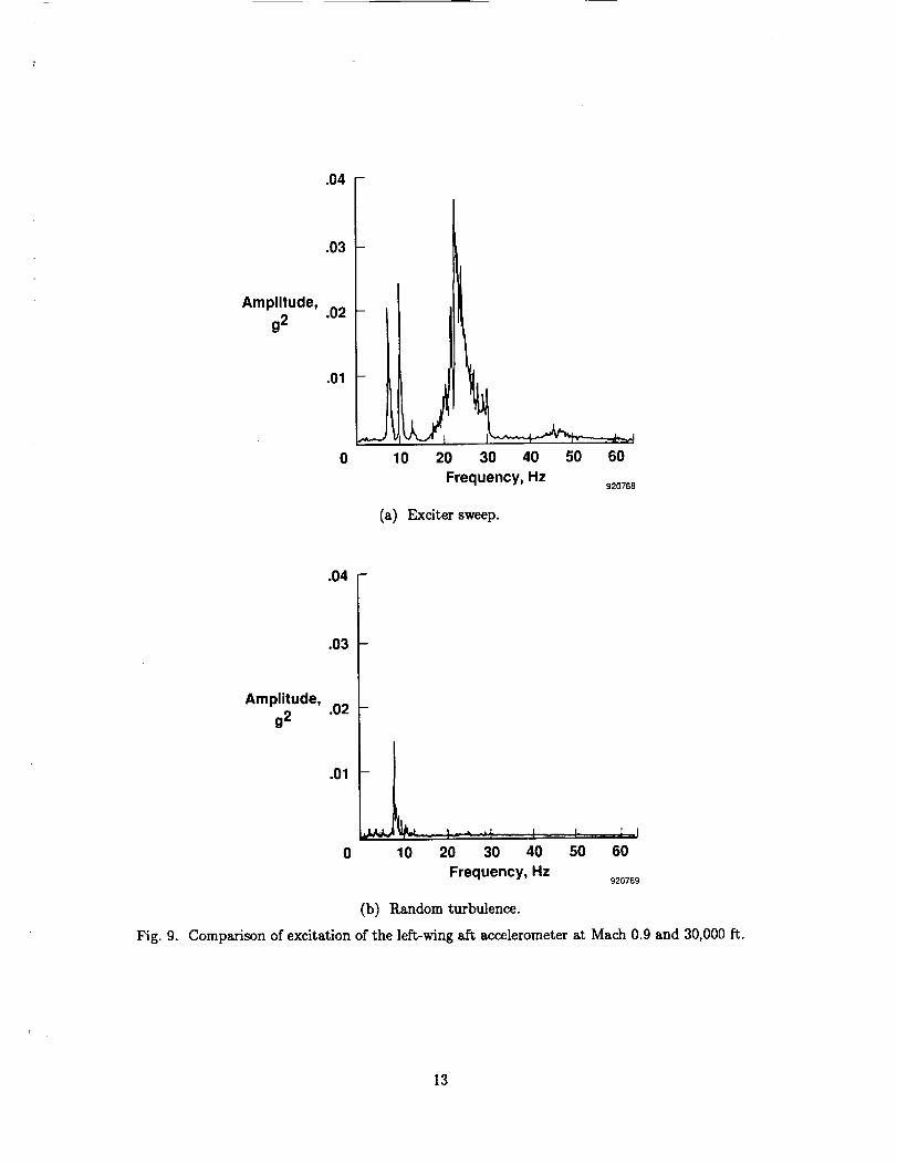
damping estimates were obtained at each flight condi-tion for each type of excitation. The power spectral
density plots shown in Fig. 9 are a comparison of the
left-wing response caused by random atmospheric tur-bulence and forced excitation from the exciter vane.
3
At this flightcondition,Mach0.9at 30,000 ft, the pi-
lot reported encountering light to moderate turbulence.From the atmospheric turbulence excitation only the
8 Hz mode is well excited. Natural atmospheric turbu-
lence did not excite any structural modes above 14 Hz.
All expected structural modes were excited by the ex-citer vane. This data clearly indicate that the exci-
tation provided by the exciter vane was superior to
natural atmospheric turbulence.
The most critical flutter frequencies for this airplane
configuration are predicted to be in the range of 20 to30 Hz. It is especially important that such modes be
excited during flight flutter testing to ensure detection,subcritically, of impending aeroelastic instabilities. In
this example, the exciter vane provided excitation at
these frequencies while atmospheric turbulence did not.
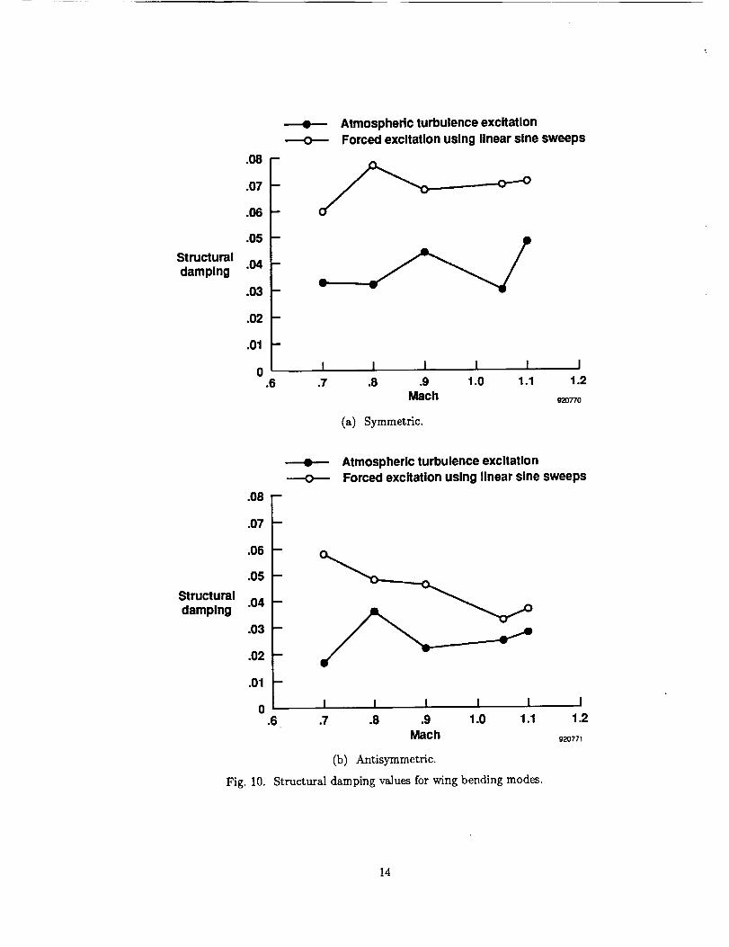
For every flight condition, the forced excitation data
yielded higher structural damping values than thosefrom the atmospheric turbulence data. Figure 10 shows
a graph of the structural damping values for the sym-metric and antisymmetric wing bending modes. The
structural damping estimates for the forced excitationdata are often as much as twice the value of the data
for the atmospheric turbulence. Figure 9 also reflects
this phenomena. The width of the peaks, which is pro-
portional to structural damping, is clearly smaller forthe atmospheric turbulence data than for the forcedexcitation data. This is attributed to the fact that
the amplitudes for the modes excited by atmosphericturbulence have a very low signal-to-noise ratio. The
modes are not well excited and are contaminated by
noise; therefore, the damping levels are difficult to cal-
culate accurately.
Static Forces
The exciter vane was mounted at 0 ° with respect
to the launcher rail. When it was installed, no at-
tempt was made to determine a mounting angle thatwould minimize static loads at the planned flight con-
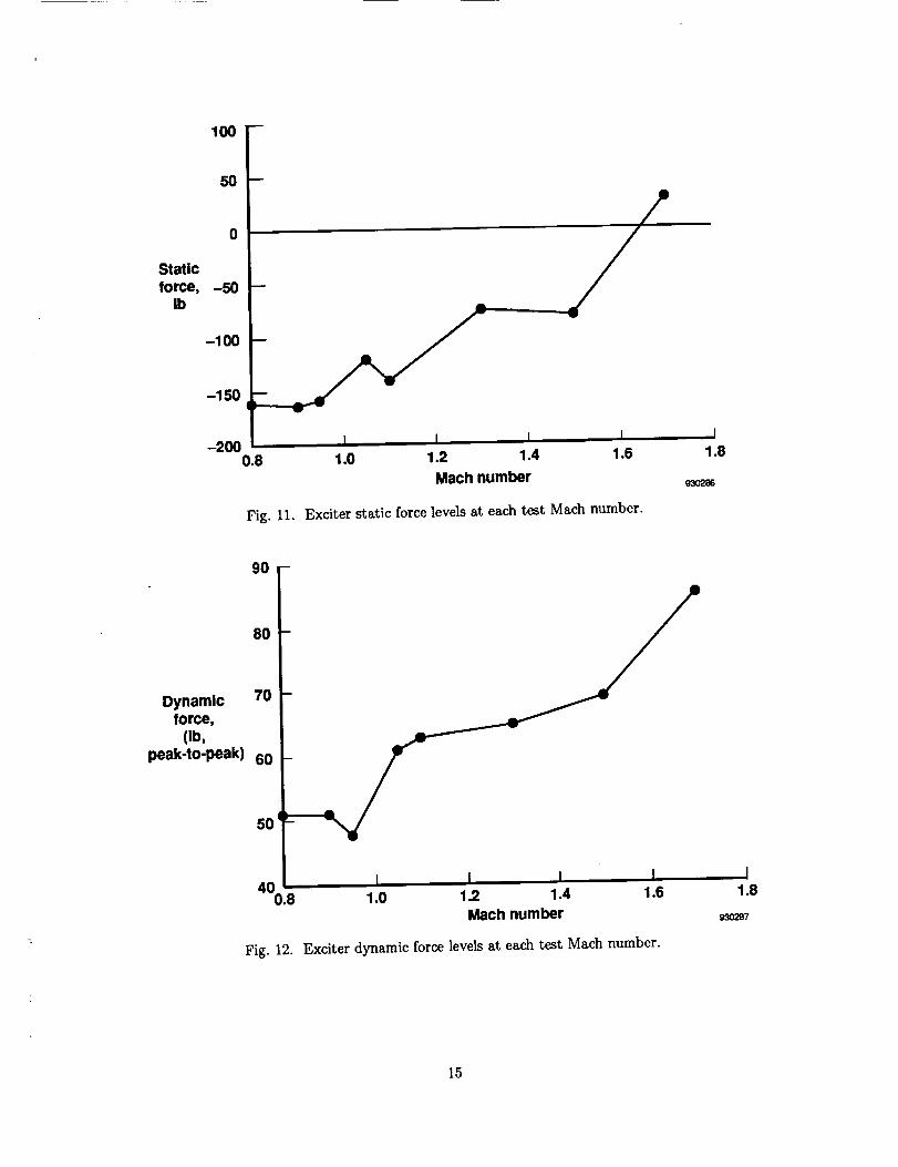
ditions. Figure 11 shows the static loads generated ateach Mach number. At Mach 0.8, the aircraft was at an
angle of attack of 6.5 °, and the vane generated 160 lb ofupward force. The magnitude of the static loads de-creased until the aircraft reached Mach 1.7, with an
aircraft angle of attack of 2 °, when 30 lb of downwardforce was measured. The local angle of attack of the
exciter vane was not measured.
Dynamic Forces
The dynamic forces generated by the exciter vane ateach Mach number are shown in Figure 12. The forces
shown are given in pounds, peak to peak, and are all for
the high force setting (cylinder slot 75 percent open).
Overall, the average dynamic force increased with
increasing Mach number, which was expected because
dynamic pressure was also increasing. The dynamicforces ranged from about 50 lb at Mach 0.8 to almost
90 lb at Mach 1.7 (all at 30,000-ft altitude). Theseloads were less than expected. For the design condition
of Mach 1.2 at 10,000 ft (1467 lb/ft_), DEI wind-tunnel
and flight test data estimated 409 lb peak to peak for
an exciter configuration with no plug in the slotted
cylinder. 9 The flight condition of Mach 1.7, 30,000 ft
(1271 lb/ft _) was therefore expected to be close to that.The difference may be due in part to the addition of
the plug, which cut the slot opening by 25 percent, anddue to local flow conditions at the launcher rail of the
F-16XL, which may have decreased the exciter_s effec-tiveness. While less than predicted, the dynamic force
levels were more than sufficient to excite the aircraft's
structural modes of interest.
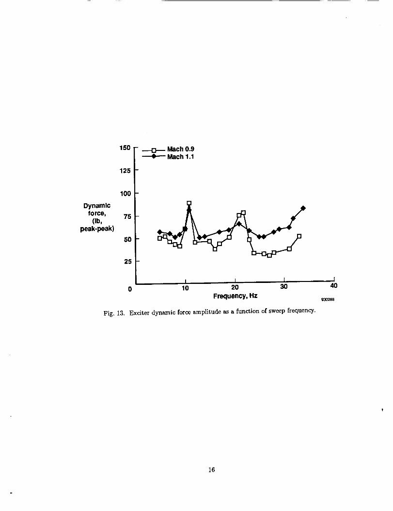
Force Roll-Off
The dynamic forces generated at Mach 0.9 and 1.1
are shown in Fig. 13 as a function of frequency. This
figure shows that the exciter vane generated adequateforce across the entire frequency range of interest (5 to
35 Hz). The force is not flat across the frequency band-width, however. The dynamic force peaks at two fre-
quencies that correspond to antisymmetric structuralmodes. The increase in force at these frequencies is
most likely caused by an inertial reaction of the exciteras these structural modes are excited. An increase in
amplitude is also seen at the sweep cut-off frequency at35 Hz. This is a result of the excitation frequency ap-
proaching the exciter vane first bending mode, whichis at 43 Hz.
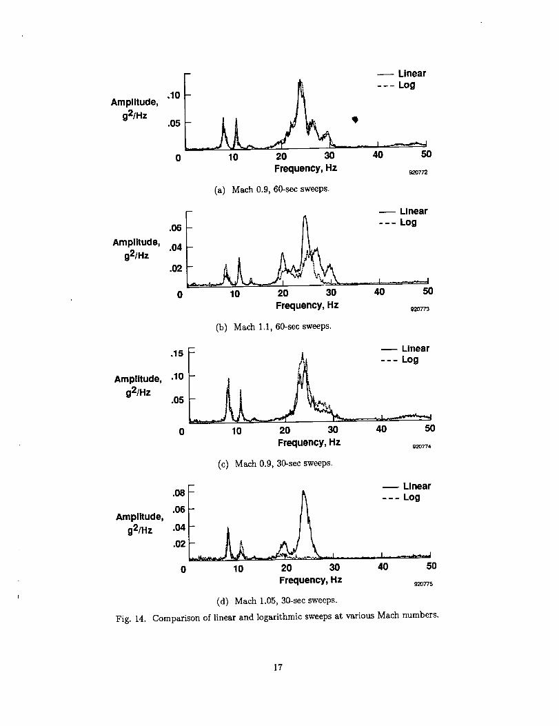
Logarithmic and Linear Sweeps Compared
Figure 14 shows a comparison of the 60-sec logarith-mic and linear sweeps at several Mach numbers for a
frequency sweep of 5 to 35 Hz. At Mach 0.9, the loga-rithmic and linear sweeps are nearly identical. As Mach
number increased, however, the logarithmic sweep didnot excite the control surface modes, from 20 to 30 Hz,
as well as the linear sweep. This trend was even more
pronounced for the 30-sec sweeps. Overall, the linearsweep was more consistent in exciting the structural
modes over the range of Mach numbers tested.
Linear Sweep Durations
To determine the effect of different sweep durations,
linear sweeps from 5 to 35 Hz were performed for 60,
30, 15, and 7 sec. Figure 15 shows a comparisonof the different sweep durations at Mach 0.8. The
30- and 60-sec sweeps are nearly identical. As the
sweep duration decreased, however, less excitation en-
ergy is transmitted to the structure, and at the 7-sec
sweep, some modes are not excited. Overall, the 30-
and60-seesweepsproduceaboutthesamelevelofre-sponse,regardlessof Machnumber,andtheselevelswereconsideredadequate.
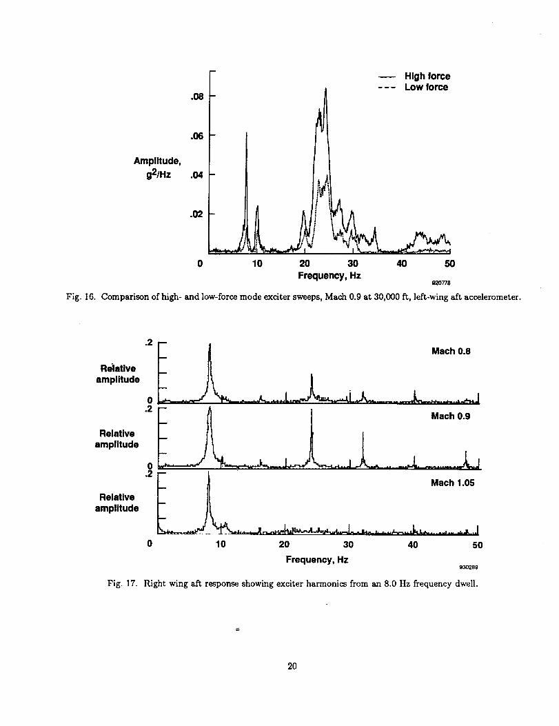
High- and Low-ForceLevels
Figure16showsa comparisonofthehigh-andlow-forcelevelsforthevaneat Mach0.9at 30,000ft. Bothforcelevelsweresufficientto excitethemodesofinter-est;however,thehigh-forcelevelprovidedconsiderablymoreenergy.Aslightfrequencyshift,asmuchas3per-centforsomefrequencies,in thedatacomparisoncanbeseeninFig.16.Astheforcewasincreased,thefre-quencyofthemodesdecreased.Thistrendisaresultofstructuralnonlinearitiesandiscommonlymeasuredduringgroundvibrationtests.1°ttarmonic Excitation
The exciter producedharmonicswhich excitedmodeshigherthanthe primarysweepfrequency.Anexampleof theharmonicexcitationisseenin Fig.17,whichshowsan8.0-Hzfrequencydwellandthe har-monicsproducedbythevaneat Machnumbersof 0.8,0.9,and1.05.Theharmonicsappearto havethehigh-estamplitudein thetransonicMachnumberrange.
Anotherexampleoftheharmonicexcitationisseenin Fig. 8, in whicha modeat 43Hz wasobserved.The43-Hzmodeis the exciter'sfirst vanebendingmode,measuredfromagroundvibrationtestdoneonthevane,andit wasexcitedwhilethesweeppassedthrough21.5Hz. Thiseffectcanbeseenmoreclearlyin Fig.18.Here,theexciterhassweptthrougha fre-quencyrangeof5to 15Hz,andthedataindicatethatthemodesin the 15-to 30-Hzfrequencyrangehavealsobeenexcited.Thiseffectmaynotbedesirable,asin thecaseof excitingthevane'sfirstbendingmode,or if asinglefrequencydwellisrequired.Excitation Energy Distribution
Duringtheevaluationflights,thevaneassemblywasmountedontheleftwingtipoftheaircraft.Accelerom-etersweremountedbothontheleft andrightwingtips.Theresponsefromtheseaccelerometerswasusedtomeasurethe energytransferredfromtheleft wingtotherightwingduringexciteroperation.
Figure19comparesthepowerspectraldensityoftheleft-wingresponsewith that of theright wing. Thesymmetricandantisymmetricwingbendingmodes(8and10.8Hz)wereexcitedwellonbothwingtips;how-ever,the13.2-Hzlauncherpitchmodewasnotexcitedon the right wing. Theexciter,aswellasthe aftaccelerometer,wasplacednearthenodelinefor thismode.Therewassufficientenergyto excitethismodeontheleftsideoftheairplane,whichisseenin theleft-wingforwardaccelerometerresponse.Therewasinsuf-ficientenergy,however,toexcitethismodeontheright
sideof theairplane.In addition,thehigherfrequencycontrolsurfacemodeswerenot excitedaswellontheright wingwhen_comparedto the left wing. Overall,themodesabove20Hzwerenotexcitedwellonthesideoppositetheexciter.Thisdeficiencycouldbeovercomeby addinganexciterto therightwing-tip.
Conclusions
A vane and rotating slotted cylinder excitation sys-
tem was flight-tested to investigate the exciter's effec-tiveness in the subsonic and transonic flight regimes.
The objectives for the flight tests, to determine the
system's ability to develop adequate force levels to ex-cite the aircraft's structure and to determine the fre-
quency range over which the system could excite struc-tural modes on the aircraft, were met. In addition,
studies were conducted to determine optimal excitation
parameters, such as sweep duration, type, and energylevels.
The structural response data quality obtained with
the exciter was superior to that obtained with random
atmospheric turbulence. The vane and rotating cylin-
der assembly excited all expected modes of the aircraft
in a frequency bandwidth of 5 to 35 Hz, while the atmo-
spheric turbulence only excited the wing's first bending
mode. By using atmospheric turbulence excitation, acritical flutter mode may not be excited during flutter
testing. A structural excitation system that adequatelyexcites all modes of interest is required to verify the ab-
sence of flutter within an airplane flight envelope.
In general, the best results were obtained with 30-
and 60-see linear frequency sweeps. Shorter duration
sweeps and logarithmic sweeps did not always suffi-
ciently excite the structural modes above 20 Hz.
The vane and rotating cylinder system produced har-monics that excited modes above the primary sweep
frequency and outside of the selected excitation fre-quency bandwidth. This had an undesirable effect inthat the exciter first vane bending mode at 43 Hz wasexcited. The excitation of this mode could lead to high
dynamic loads on the exciter vane.
Because the exciter system was mounted on the left
wingtip of the aircraft, the energy distribution to the
right side of the aircraft was evaluated. The symmet-
ric and antisymmetric wing bending modes were ex-cited well on both wingtips; however the launcher pitch
mode was not excited on the right wing. In addition,modes above 20 Hz were not excited well on the side
opposite the exciter. This deficiency could be overcome
by adding an exciter to the right wing-tip.
Overall, the relatively simple installation require-
ments, precise excitation control, low-power require-
ments, and effectiveness over a large frequency range
areall aspectsthatqualifythevaneandrotatingcylin-
der concept as a viable solution for safer, more effective
flutter testing.
References
aKehoe, Michael W., Aircraft Flight Flutter Testing
at the NASA Ames-Dryden Flight Research Facility,
NASA TM-100417, May 1988.
2Norton, Capt. William J., "Random Air Turbu-lence as a Flutter Test Excitation Source," Proceed-
ings, 20th Annum Symposium, Society of Flight Test
Engineers, Reno, Nevada, 1989, pp. 6.4-1-6.4-11.
3Goldman, A., C.D. Rider, and P. Piperias, "Flutter
Investigations on a Transavia PL12/T-400 Aircraft,"Aeronautical Research Laboratories, Melbourne, Aus-
tralia, July 1989.
4Van Nunen, J.W.G., and G. Piazzoli, "Volume
9: Aeroelastic Flight Test Techniques and Instrumen-tation," AGARD Flight Test Instrumentation Series,
AG-1606, Feb. 1979.
5Kehoe, Michael W., Flutter and Aeroservoelastic
Clearance o/the x-$gA Forward-Swept Wing Airplane,
NASA TM-100447, Sept. 1989.
6Larue, Pierre, Maurice Millet, and Gerard Piaz-
zoli, "Pyrotechnic Bonkers for Structural Tests in
Flight," La Recherche Aerospatiale, May-June 1974,
pp. 137-146.
treed, Wilmer H., III, "A New Flight Flutter Ex-
citation System," Proceedings, Society of Flight Test
Engineers, 19th Annual Symposium, Arlington, Texas,
Aug. 14-18, 1988.
8Bensinger, C.T., "F-16XL Flight Flutter Tests,"
General Dynamics, 400PR100, July 20, 1983.
9Dynamic Engineering Inc., "F-16XL Flutter ExciterModel Stress Report," DEI Document No. D-348, Aug.1992.
1°Kehoe, M.W., "F-15 A/B Nestable Fuel TankGround Vibration, Flight Flutter and Loads Demon-
stration Test Program," U.S. Air Force Flight TestCenter, Report AFFTC-TR-79-14, May 1979.
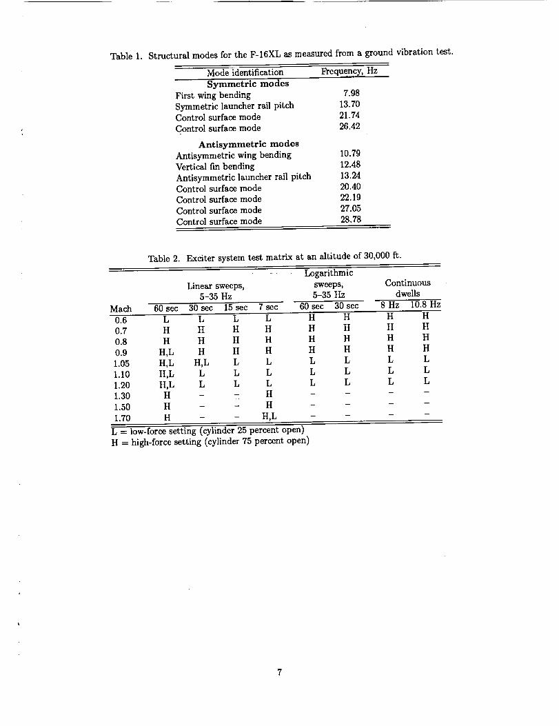
Table1. StructuralmodesfortheF-16XLasmeasuredfromagroundvibrationtest.
Modeidentification Frequency,HzSymmetric modes
First wing bending 7.98
Symmetric launcher rail pitch 13.70Control surface mode 21.74
Control surface mode 26.42
Antisymmetric modes
Antisymmetric wing bending 10.79
Vertical fin bending 12.48
Antisymmetric launcher rail pitch 13.24Control surface mode 20.40
Control surface mode 22.19
Control surface mode 27.05
Control surface mode 28.78
Table 2. Exciter system test matrix at an altitude of 30,000 ft.
Mach 60 sec
: Logarithmic
Linear sweeps, sweeps,5-35 Hz 5-35 Hz
30sec 15sec 7sec 60sec 30 see
0.6 L L L L H H
Continuous
dwells
8 Hz 10.8 Hz
H H
0.7 H H H H H H
O.8 H H H H H H
O.9 H,L H H H H H
1.05 H,L H,L L L L L
1.10 H,L L L L L L
1.20 H,L L L L L L1.30 H - - H - -
1.50 H - - H - -
1.70 H - - H,L - -
H H
H H
H HL L
L L
L L
L -- low-force setting (cylinder 25 percent open)
H -- high-force setting (cylinder 75 percent open)
7

Fig. 1. F-16XL with vane and rotating slotted cylinder excitation system.
Left wlng aft
Exclter vane
Left wlng forward
Left aileron beam
Vertical tall
Fuselage vertical
Fuselage lateral
Right aileron
Right wing aft--,,
Fig. 2.
Rlght wlng forward
Accelerometer locations on the F-16XL aircraft.
92O761

r
EC90--282--3
Fig" 3" The excitation system's three components: electronics box, vane and rotating cylinder assembly, andcockpit control box.
A
Airflow
Fig. 4. Exciter vane and rotating slotted cylinder.
9
_mm_m_mmmm_m
I!̧| L _-:''--- --'-------"---- .-_" -
Side view Planform view _763
Fig. 5. Planform and side views of exciter.
B(_ c,_C "_" (force) Time
Fig. 6. Periodic lift force generated by exciter.
920764
10
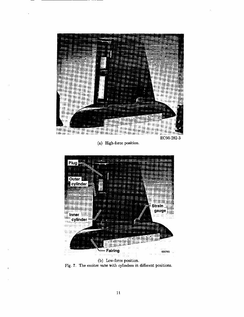
(a) High-force position.
EC90-282-3
i Fairing 920765
(b) Low-force position.Fig. 7. The exciter vane with cylinders in different positions.
11
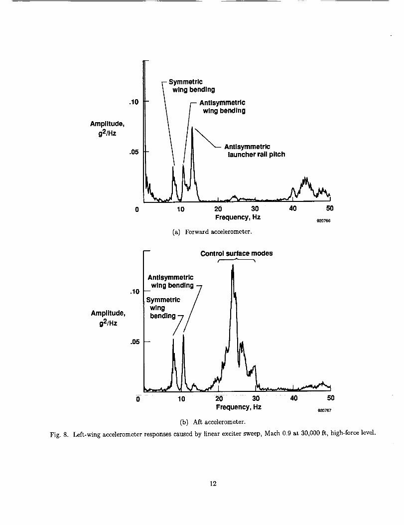
Amplitude,g2/Hz
.10
.05
0
Symmetricwing bending
- // Antisymmetric
_- wing bending
_-- Antlsymmetrlc
launcher rail pitch
10 20 30 40 50Frequency, Hz
92O766
(a) Forward accelerometer.
Fig. 8.
-- Control surface modes
Antlsymmetrlc
wing bending 7.10 Symmetric /
wing /
Amplitude,g2/Hz bending;7 /
.05 -- / --
0 10 20 30 40 50
Frequency, Hz920767
(b) Aft accelerometer.
Left-wing accelerometer responses caused by linear exciter sweep, Mach 0.9 at 30,000 ft, high-force level.
12
Amplitude,
g2
.04
.03
.O2
.01
0 10 20 30 40 50 60
Frequency, Hz920768
(a) Exciter sweep.
Fig. 9.
Amplitude,
g2
.O4
.03
.O2
.01
0 10 20 30 40 50 60
Frequency, Hz920769
(b) Random turbulence.
Comparison of excitation of the left-wing aft accelerometer at Mach 0.9 and 30,000 ft.
13
Structuraldamping
.08
.07
.06
.05
.04
.03
.02
.01
0
Atmospheric turbulence excitationForced excitation using linear sine sweeps
i
m
m
m
m
I.6 .7
I I I I l,8 ,9 1.0 1.1 1.2
Mach _o_o
(a) Symmetric.
Structuraldamping
.08 -
.07 --
.06 -
.05 -
.04 -
.03 -
.02 -
.01 -
0.6
----e---- Atmospheric turbulence excitation---O--- Forced excitation using linear sine sweeps
If
I i
.7 .8
I I i I.9 1.0 1.1 1.2
Mach 920771
(b) Antisymmetric.
Fig. 10. Structural damping values for wing bending modes.
14
5O
0
Staticforce, -50
Ib
-100
-150
-200 I I ] I I0.8 1.0 1.2 1.4 1.6 1.8
Mach number
Fig.11. Exciter static force levels at each test Mach number.
9O
8O
Dynamic 70force,
(Ib,peak-to-peak) 60
50
40).8
Fig. 12.
I I I I1.0 1.2 1.4 1.6
Mach number
Exciter dynamic force levels at each test Mach number.
I1.8
93O287
15
150
125
100
Dynamic
force, 75(Ib,
peak-peak)
50
Fig. 13.
25
----D-- Mach 0.9Mach 1.1
0I I I
10 20 30
Frequency, Hz
Exciter dynamic force amplitude as a function of sweep frequency.
I40
930288
16
Amplitude,
g2/Hz
.10
.05
- -- Linear
_ _,.___j_,. --- Log
10 20 30 40 50
Frequency, Hz 920772
(a) Mach 0.9, 60-sec sweeps.
Amplitude,
g2/Hz
.06
.04
.02
0
- _ Linear
_ _ --- Log
m
_- .... _! --:: _-I
10 20 30 40 50
Frequency, Hz _Tt3
(b) Mach 1.1, 60-sec sweeps.
Amplitude,
g2/Hz
.15
.10
.05
- _ Linear
: ,ooJk
10 20 30 40 50
Frequency, Hz o2o774
(c) Mach 0.9, 30-sec sweeps.
Amplitude,
g2/Hz
i
.08 -
.06 -
,04 - a...___ M_-".02 -
0 10
. ._ _._.1 _ _
20 30
Frequency, Hz
Linear--- Log
40 50
92O775
(d) Mach 1.05, 30-sec sweeps.
Fig. 14. Comparison of linear and logarithmic sweeps at various Mach numbers.
17

Fig. 15.
4 60 sec
2
g 0
-2!
0 10I I I i I
20 30 40 50 60
Time
g
4 30sec
2
0
-2I
0 51 I I i I
10 15 20 25 30Time
4
2
0
-2I I l
0 5 10Tlme
4 7 sec .J
2g 0
-2I I I I
0 2 4 6
Time _o_8(a) Time history plots.
Linear sweep duration variations, Mach 0.8 at 30,000 ft, left-wing aft accelerometer, high-force mode.
18

5 F 60 sec
Amplitude, 2.5
Amplitude, 2.5g
0
30 sec
Amplitude,g
5 I 15 sec
2.5 [i
Amplitude,g
5 r 7 sec
k2.5
0 10 20 30 40 50
Frequency, Hz920777
(b) Power spectraldensityplots.
Fig.15. Concluded.
19
Amplltude,
g2/Hz
.O8
.O6
.O4
.O2
0
-- High force- -- Low force
/IJ
F
10 20 30 40 50
Frequency, Hz82O778
Fig. 16. Comparison of high- and low-force mode exciter sweeps, Mach 0.9 at 30,000 Pc,left-wing aft accelerometer.
Relative
amplitude
Relative
amplitude
Relativeamplitude
Fig. 17.
.2
0.2
0.2
0
Mach 0.8
.._L..,,,_ _,_ .... ._.L._..,__,.J
Mach 0.9
Maeh 1.05
10 20 30 40 50
Frequency, Hz930289
Right wing aft response showing exciter harmonics from an 8.0 Hz frequency dwell.
2O


i
Form ApprovedREPORT DOCUMENTATION PAGE OM.No.o;,o4-o1
o=ther_Oandmalrd_lngthedmanee_o,=rid¢om!_mg=nor_ me_=u_. = ,..,.,,,_=,_. _..- --:::.-: .... ._d._-'-_r= ,bu_............ -_...., = ,..,,.-._
_,_,_ VA 2220_ -_L'tn_ atKI to the Office of M _ ino uuog_. P.aperwo_ _,_u_ _-_uF_.a tv,v._v,_.._--,_, . -DavisHlghway...... 1204.Arington. .... _mage1. AGENCY USE ONLY (Leave blank) 2. REPORT DATE 3. REPORTTYPE AND DATES COVERED
June 1993 Technical Memorandum
4. TITLE AND SUBTITLE S. FUNDING NUMBERS
In-flight Investigation of a Rotating Cylinder-Based Structural Excitation
System for Flutter Testing.
6. AUTHOR(S)
Lura Vernon
7. PERFORMING ORGANIZATION NAME(S) AND ADDRF._F..S)
NASA Dryden Flight Research FacilityP.O. Box 273
Edwards, California 93523-0273
9. SPONSORINGtMONOTORING AGENCY NAME(S) AND ADDRESS(F.S)
National Aeronautics and Space Administration
Washington, DC 20546-0001
WU 505-63-50
8. PERFORMING ORGANIZATIONREPORT NUMBER
H-1883
10, SPONSORING/MONITORINGAGENCY REPORTNUMBER
NASA TM-4512
11. SUPPLEMENTARYNOTESA version of this was prepared as AIAA-93-1537, presented at the AIAA 34th Structures, Structural Dynamics,
and Materials Conference, April 19-22, 1993 at La JoUa, California.
121. DISTRIBUTION/AVAILABILITY STATEMENT
Unclassified_Unlimited
Subject Category 05
12b. DISTRIBUTION CODE
13. ABSTRACT (Maximum 200 words)
A research excitation system was test flown at the NASA Dryden Flight Research Facility on the two-seat
F-16XL aircraft. The excitation system is a wingtip-mounted vane with a rotating slotted cylinder at the trail-
ing edge. As the cylinder rotates during flight, the flow is alternately deflected upward and downward through
the slot, resulting in a periodic lift force at twice the cylinder's rotational frequency. Flight testing was con-ducted to determine the excitation system's effectiveness in the subsonic, transonic, and supersonic flight
regimes. Primary research objectives were to determine the system's ability to develop adequate force levels toexcite the aircraft's structure and to determine the frequency range over which the system could excite struc-
tural modes of the aircraft. In addition, studies were conducted to determine optimal excitation parameters,
such as sweep duration, sweep type, and energy levels. The results from the exciter were compared with resultsfrom atmospheric turbulence excitation at the same flight conditions. The comparison indicated that the vane
with a rotating slotted cylinder provides superior results. The results from the forced excitation were of higher
quality and had less variation than the results from atmospheric turbulence. The forced excitation data also
invariably yielded higher structural damping values than those from the atmospheric turbulence data.
14. SUBJECT TERMS
Aeroelasticity, Flutter testing, In-flight structural excitation
17. SECURITY CLASSIFICATION 18. SECURITY CLASSIFICATION 19. SECURITY CLASSIFICATIONOF REPORT OF THIS PAGE OF ABSTRACT
Unclassified Unclassified Unclassified
_ISN7540-01-280-5500 Availablefrom_e NASA Center torAeroSpaceInfocrnation,800 ElkridgeLandingRoad,IJnthicumHeights,MD 21090; (301)621-0390.
15. NUMBER OF PAGES
2416. PRICECODE
AO320. LIMffA_ON OF ABSTRACT
Unlimited
andardForm298 (Rev.2-89)_._._ _,,s_ s,,,,,z_.._29_102