IN-DIE TAPPING TOOLS - Danly · The special forming taps used in the in-die taping units are...
42
© 2004 Danly IEM, A Division of Connell Limited Partnership IN-DIE TAPPING TOOLS TECHNICAL INFORMATION MANUAL CALL TOLL FREE: 1-800-243-2659 FAX: 1-800-833-2659
Transcript of IN-DIE TAPPING TOOLS - Danly · The special forming taps used in the in-die taping units are...

© 2004 Danly IEM, A Division of Connell Limited Partnership
IN-DIE TAPPING TOOLS
TECHNICAL INFORMATION MANUAL
CALL TOLL FREE: 1-800-243-2659FAX: 1-800-833-2659

1
www.danly.com
THIS MANUAL CONTAINS INFORMATION APPLICABLETO THE FOLLOWING IN-DIE TAPPING TOOL MODELS:
HY1024
ME1024
LP25M6
♦ PRODUCT SPECIFICATIONS 2
♦ ACCESSORIES 5
♦ TAPPING DEPTH/MATERIAL THICKNESS CHARTS 8
♦ FORMING TAP PRE-HOLE SIZE CHARTS 9
♦ APPLICATION DRAWINGS 11
♦ DESIGNING A CAM DRIVER 38
♦ RAPID T.A.P. CAM DESIGN SOFTWARE INTRODUCTION 39
♦ TROUBLE SHOOTING 40
(Patent #5173015)
TABLE OF CONTENTS PAGE NUMBER

2
www.danly.com
HY1024 Seriesfor Hydraulic Presses
The HY is the smallest and most compact of the tapping tools.The HY1024 is an economical solution for tapping from the top downin a hydraulic press. Since the HY1024 is not cam actuated, the presscontrols the acceleration and tap speed. The HY1024 will tap size#0 - #12 or up to M5 and typically runs at production rates between60 - 100 strokes per minute up to a maximum 200 (SPM) rate basedon strip material, tap size and tap pitch.
By utilizing multiple tools in place of one special tapping tool, youcan control flexibility in the stamping operation and greatly reducedowntime due to unscheduled maintenance.
Product Features
HY1024
HY1024 footprint dimensions
Notes: ♦ Tapping depth/maximum material thickness can be found on Page 8.♦ Metric dimensions are in italics.
NOTES:
♦ The HY1024 tapping tool cannot be used in a mechanical press. See the ME1024 or the LP25M6 forapplications requiring use in a mechanical press.

3
www.danly.com
The ME1024 is a simple and compact tool with a small footprintfor tapping top down in a mechanical or hydraulic press. The ME1024utilizes a cam driver to control tool acceleration. The ME will tap size#0 - #12 or up to M5 and typically runs at production rates between60 - 100 strokes per minute up to a maximum of 200 (SPM) basedon strip material, tap size and pitch.
The cam driver is designed as a separate functional piece to maximizedie design flexibility and take the sinusoidal motion that is inherentwith mechanical presses and turn it into a rotary tapping motion. Thecam driver mounts easily on a punch plate or upper die shoe above thetapping tool. The cam driver is application specific and can bemanufactured by using the free “Rapid TAP” CAD design software.
By utilizing multiple tools in place of one special tapping tool, youcan control flexibility in the stamping operation and greatly reducedowntime due to unscheduled maintenance.
Product Features
ME1024 Seriesfor Mechanical Presses
ME1024
Notes: ♦ Tapping depth/maximum material thickness can be found on Page 8.♦ All dimensions are in inches.
A = TAPPING STROKE + 5.776
ME1024 footprint dimensions

4
www.danly.com
The LP is the most versatile tool with a simple and compact designfor tapping top down, bottom up or at any angle. The LP utilizes a camdriver to control tool acceleration and tap speeds. The LP25M6 will tapsize #0 - 1/4 or M6 and the LP516M8 will tap 1/4" - 5/16" or M8 whilemaking either right or left-hand threads. The LP typically runs atproduction rates between 20 - 60 strokes per minute up to a maximumof 100 (SPM) based on strip material, tap size and pitch.
The cam driver is designed as a separate functional piece tomaximize die design flexibility and take the sinusoidal motion that isinherent with mechanical presses and turn it into a rotary tapping motion.The cam driver mounts easily on a punch plate on the upper die shoeabove the tapping unit to provide the proper amount of tap accelerationand a positive return. The cam driver is application-specific and can bemanufactured by using the free “Rapid TAP” CAD design software.
By utilizing multiple tools in place of one special tapping tool, youcan control flexibility in the stamping operation and greatly reducedowntime due to unscheduled maintenance.
LP25M6 & LP516M8 Seriesfor Mechanical Presses
LP25M6
Product Features
Notes: ♦ Footprint dimensions are identical for both units.However, performance variations exist between thetwo units. Consult the Rapid Tap software.
LP25M6 & LP516M8 footprint dimensions
NOTE A: Dowel pin holes ±0.001Fastener holes ±0.005
The shut height from the bottom of the upper shoe to themounting surface of the unit cannot be less than 3.775",unless modified (see installation manual).
ImportantNote
LP Cam Driver profile
♦ Tapping depth/maximum material thickness can befound on Page 8.
♦ All dimensions are in inches.
5
www.danly.com
Accessories andReplacement Parts
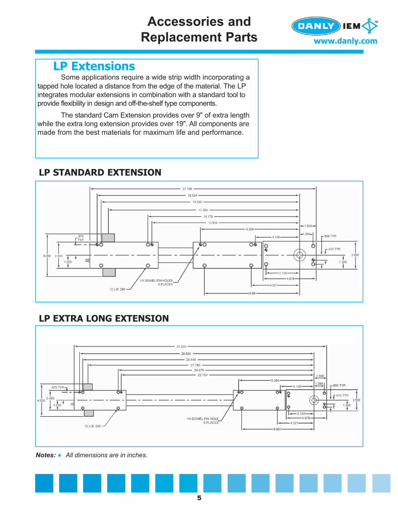
LP STANDARD EXTENSION
LP EXTRA LONG EXTENSION
Some applications require a wide strip width incorporating atapped hole located a distance from the edge of the material. The LPintegrates modular extensions in combination with a standard tool toprovide flexibility in design and off-the-shelf type components.
The standard Cam Extension provides over 9" of extra lengthwhile the extra long extension provides over 19". All components aremade from the best materials for maximum life and performance.
LP Extensions
Notes: ♦ All dimensions are in inches.

6
www.danly.com
Accessories andReplacement Parts
The special forming taps used in the in-die taping unitsare available in inch and metric standard sizes listed below. Allforming taps are sold with a TiN coating as standard. Othercoatings for special material applications are available onrequest. Forming taps provide a superior quality and finish ofthread, with no chip formation.
Forming Taps —Product Features
R-006004 Small 2 - 56 - RH3R-006008 Small 4 - 40 - RH5R-006033 Small 4 - 40 - RH7R-006010 Small 5 - 40 - RH5R-006013 Small 6 - 40 - RH5R-006009 Small 4 - 48 - RH5R-006012 Small 6 - 32 - RH5R-006031 Small 6 - 32 - RH7R-006014 Small 8 - 32 - RH5R-006030 Small 8 - 32 - RH7R-006017 Small 10 - 32 - RH6R-006032 Small 10 - 32 - RH8R-006016 Small 10 - 24 - RH6R-006019 Small 12 - 28 - RH6R-006018 Small 12 - 24 - RH6R-006021 Medium 1/4 - 28 - RH6R-006090 Large 1/4 - 28 - RH6R-006020 Medium 1/4 - 20 - RH6R-006091 Large 1/4 - 20 - RH6R-006092 Large 5/16-32 – RH6R-006093 Large 5/16-24 – RH6R-006094 Large 5/16-18 – RH7
INCH SIZES
Part Number Shank Size1 Tap Size & D Limit
R-006042 Small M2.0 x .40 D5R-006044 Small M2.5 x .45 D5R-006045 Small M3.0 x .50 D5R-006046 Small M3.5 x .60 D6R-006047 Small M4.0 x .70 D6R-006049 Small M5.0 x .80 D7R-006050 Medium M6.0 x 1.00 D8R-006095 Large M6.0 x 1.00 D8R-006096 Large M8.0 x 1.00 D8R-006097 Large M8.0 x 1.25 D8
METRIC SIZES
Part Number Shank Size1 Tap Size & D Limit
Taps are sold in packs of 12.
Standard Stock Taps are TiN CoatedSpecial Tap Sizes, Pitches and Coatings are Available per Quotation
1 Tap diameter shank size application:♦ Small – 0 - #12 (M2 – M5) diameter taps: use in HY1024, ME1024, LP25M6♦ Medium – ¼" (M6) diameter taps: use in LP25M6♦ Large – ¼" – 5/16” (M6 - M8) diameter taps: use in LP516M8

7
www.danly.com
METRIC SIZESTap Part Part Part
Holder Number Number NumberPitch Size1 for for for
HY/ME1024 LP25ME LP516M80.40 mm Small R-002048 R-002068 —0.45 mm Small R-002047 R-002067 —0.50 mm Small R-002046 R-002066 —0.60 mm Small R-002045 R-002065 —0.70 mm Small R-002044 R-002064 —0.80 mm Small R-002042 R-002062 —1.00 mm Medium — R-002060 —1.00 mm Large — — R-0021161.25 mm Large — — R-002117
INCH SIZESTap Part Part Part
Holder Number Number NumberPitch Size1 for for for
HY/ME1024 LP25ME LP516M856 Small R-002005 R-002024 —48 Small R-002006 R-002025 —40 Small R-002007 R-002026 —32 Small R-002008 R-002027 —28 Small R-002009 R-002028 —28 Medium — R-002031 —28 Large — — R-00211224 Small R-002010 R-002029 —24 Large — — R-00211320 Medium — R-002030 —20 Large — — R-00211418 Large — — R-002115
Pitch inserts are interchangeable components of the tapping operation and are specific tothe tap pitch of the tapped hole. Each pitch insert contains a tap holder with a quick releasedepression collar. Taps can easily be changed within seconds in most applications.
For applications needing a little extra reach to tap inside an embossment, a pitch insertextension can be made specific to your needs. Our engineering department will work with youon your specific application.
Pitch Inserts/Tap Holders —Product Features
Accessories andReplacement Parts
Pitch insert for non-standard sizes orpitches are by quotation.
1 Tap diameter shank size application:♦ Small – 0 - #12 (M2 – M5)
diameter taps: use inHY1024, ME1024, LP25M6
♦ Medium – ¼" (M6) diametertaps: use in LP25M6
♦ Large – ¼" – 5/16" (M6 - M8)diameter taps: use in LP516M8

8
www.danly.com
Maximum Tapping Depth/Material Thickness
NOTE: Maximum material thickness (T) includes extrusion height and .020 inch (or 0.5mm) gap betweenthe tip of the tap and the top of the material stock.
MAXIMUM MATERIAL THICKNESS (T) - INCHSize and HY & ME
Pitch 1024 LP25M6 LP516M8
2-64 0.080 0.168 —2-56 0.091 0.194 —3-56 0.091 0.194 —3-48 0.106 0.230 —4-48 0.106 0.230 —4-40 0.128 0.253 —5-44 0.116 0.280 —5-40 0.128 0.280 —6-40 0.128 0.280 —6-32 0.159 0.272 —8-36 0.142 0.261 —8-32 0.159 0.261 —10-32 0.159 0.261 —10-24 0.213 0.248 —12-28 0.182 0.248 —12-24 0.213 0.230 —1/4-28 — 0.230 0.3191/4-20 — 0.205 0.305
5/16x32UN — — 0.2775/16x24UN — — 0.3555/16x18UN — — 0.286
MAXIMUM MATERIAL THICKNESS (T) - METRICSize and HY & ME
Pitch 1024 LP25M6 LP516M8
M2 x .4 2.0 4.2 —M2.5 x .45 2.2 4.8 —
M3 x .5 2.5 5.4 —M3 x .6 3.0 6.6 —
M3.5 x .6 3.0 6.6 —M4 x .7 3.5 6.9 —M5 x .8 4.0 6.6 —M5 x .9 4.5 6.2 —M6 x 1.0 — 5.9 8.9M8 x 1.0 — — 8.9M8 x 1.25 — — 8.2

9
www.danly.com
65% THREAD 70% THREAD 75% THREADTAP SIZE/ THEOR. HOLE THEOR. HOLE THEOR. HOLE
PITCH (mm) SIZE (mm) SIZE (mm) SIZE (mm)M3 x 0.5 2.779 2.762 2.745M3 x 0.6 2.735 2.714 2.694
M3.5 x 0.6 3.235 3.214 3.194M4 x 0.4 3.823 3.809 3.796M4 x 0.7 3.691 3.667 3.643
M4.5 x 0.75 4.169 4.143 4.118M5 x 0.8 4.646 4.619 4.592M5 x 0.9 4.602 4.572 4.541M6 x 1.0 5.558 5.524 5.490
M6.3 x 1.0 5.858 5.824 5.790M7 x 1.0 6.558 6.524 6.490M8 x 1.0 7.558 7.524 7.490M8 x 1.25 7.448 7.405 7.363M10 x 1.25 9.448 9.405 9.363M10 x 1.5 9.337 9.286 9.235M12 x 1.25 11.448 11.405 11.363M12 x 1.75 11.227 11.167 11.108
METRIC COLDFORMING TAPS
NOTE: The shaded pre-hole sizes in the above table have been changed, as they wereincorrectly calculated in earlier versions of this manual.
PRE-HOLE SIZE CALCULATION
Hole size = Basic Major Diameter - Percent of Full Thread x mm Pitch
147.06
Example: Find the theoretical pre-hole punch size for M8 x 1.25mm to produce 65% thread:
Hole size = 8.00 - 65 x 1.25 / 147.06= 8.00 - 0.5525= 7.448mm
NOTE: Tapping an undersize hole may result in tap breakage due to excessive torque. As astarting recommendation, 65% thread should be considered.Tapping over 75% of thread is not recommended.
Pre-Hole Sizes

10
www.danly.com
INCH COLDFORMING TAPS
PRE-HOLE SIZE CALCULATION
Hole size = Basic Major Diameter - Percent of Full Thread
Number of Threads per Inch
Example: Find the theoretical pre-hole punch size for 1/4 - 20 to produce 65% thread:
Hole size = 0.250 - 0.0068 x 65/20= 0.250 - 0.0221= 0.2279 inches
65% THREAD 70% THREAD 75% THREADTAP SIZE/ THEOR. HOLE THEOR. HOLE THEOR. HOLEPITCH (in) SIZE (in) SIZE (in) SIZE (in)0 – 80 NC 0.0545 0.0540 0.05361 – 64 NC 0.0661 0.0655 0.06501 – 72 NF 0.0669 0.0633 0.06592 – 56 NC 0.0781 0.0774 0.07692 – 64 NF 0.0791 0.0785 0.07803 – 48 NC 0.0898 0.0890 0.08843 – 56 NF 0.0911 0.0904 0.08994 – 40 NC 0.1010 0.1000 0.09934 – 48 NF 0.1028 0.1020 0.10145 – 40 NC 0.1140 0.1130 0.11235 – 44 NF 0.1150 0.1141 0.11346 – 32 NC 0.1243 0.1230 0.12216 – 40 NF 0.1270 0.1260 0.12538 – 32 NC 0.1503 0.1490 0.14818 – 36 NF 0.1518 0.1507 0.1498
10 – 24 NC 0.1717 0.1700 0.168810 – 32 NF 0.1763 0.1750 0.174112 – 24 NC 0.1977 0.1960 0.194812 – 28 NF 0.2003 0.1989 0.19781/4 – 20 NC 0.2280 0.2260 0.22451/4 – 28 NF 0.2343 0.2329 0.2318
5/16 – 18 NC 0.2879 0.2861 0.28425/16 – 24 NF 0.2941 0.2927 0.29123/8 – 16 NC 0.3474 0.3452 0.34313/8 – 24 NF 0.3566 0.3552 0.3537
7/16 – 14 NC 0.4059 0.4035 0.40117/16 – 20 NF 0.4154 0.4137 0.41201/2 – 13 NC 0.4660 0.4634 0.46081/2 – 20 NF 0.4779 0.4762 0.4745
NOTE: Tapping an undersize hole may result in tapbreakage due to excessive torque. As astarting recommendation, 65% threadshould be considered.Tapping over 75% of thread is notrecommended.
Pre-Hole Sizes

11
www.danly.com
FIGURE #1
LOW PROFILE TOOLS TAPPING FROM THE BOTTOM UP
UPPER DIE
BOTTOM DIE
MACHINED POCKETS
CAM
FOR CAM CLEARANCE
DIEDIE
MATERIAL
MATERIAL
MACHINE POCKET INDIE SET FOR DESIREHEIGHT.
STRIPPERSPACER BLOCK
(IF NEEDED)
THIS DRAWING IS SHOWING THE LP25M6 IN THE CLOSED POSITION.
8 PLACES1/4 S.H.C.S.
MACHINE GROOVE TO ALLOWPASSAGE FOR GREASE GUN.
HEEL BLOCK
NITROGEN SPRING CAN BE USED
TO ELIMINATE TOO LONG OF A DIE SPRING.
SPRING TRAVEL IS BASEDON TAPPING STROKE, PLUSPRELOAD ON MATERIAL BEFORETAPPING. (PRELOAD WILL INSURE PROPER STRIPPING FOR TAPPING.)
STRIPPER INSTEAD OF A SPRINGSTRIPPER IF DESIRED.
CUSTOMER CAN USE A BRIDGE
D-04-1002
Application Drawings

12
www.danly.com
FIGURE #2
LOW PROFILE TOOLS TAPPING FROM THE TOP DOWN
UPPER DIE
BOTTOM DIE
DIE STRIPPER
MACHINED POCKETS
CAM
SUPPORT BLOCKFOR CAM CLEARANCE
THE SUPPORT BLOCK
BOLT
S.H.C.S. TO HOLD CAM TO DIE.
LP25M6 IS BOLTED TO THE STRIPPER AND
CAM
THIS WILL ALLOW A SMALLER SHUT HEIGHT.REMOVE BRIDGE PLATE, (1.00 inch THICK)
HEEL BLOCK
D-04-1003
Application Drawings

13
www.danly.com
FIGURE #3
HEEL BLOCKS FOR LOW PROFILE TOOLS
0.9250
CAM TRACK
CAM FOLLOWER
SHIMS FOR CLEARANCE ON SET UP.
PARALLEL
0.3750
3.1000
0.5000
0.2500
1.0000
2.0000 2.6000
1.3000
0.50000.5000
45° X .02 (4PLS)
CLEARANCE POCKETS FOR CAM
0.65600.4000
0.8000
1.3120
0.2500
0.5000
X .02 (4PLS)45°
BACK HEEL BLOCK
FRONT HEEL BLOCK
BACK HEEL BLOCK
FRONT HEEL BLOCK
DRILL TAP 6-32 (3PLS)
DRILL TAP10-32 (3 PLS)
DRILL C-BORE FOR6-32 SHCS (3PLS)
DRILL C-BORE FOR10-32 SHCS (3 PLS)
1.3120
.125 RAD (2PLS)
.25 RAD (2PLS)
0.2500
0.2500
D-04-1004
Application Drawings

14
www.danly.com
FIGURE #4
POSITION FOR CAM FOLLOWERS(RIGHT-HAND THREADING ONLY)
8.125
POSITON A
POLYGON DRIVESHAFT.
D-04-1005
Application Drawings

15
www.danly.com
FIGURE #5
LP25M6 & LP516M8 CAM DRIVER MOUNTING INFORMATION
DRILL AND C-BOREFOR 1/2-13 SHCS(4PLS)
.500 DOWEL PIN(2PLS)
CAUTIONBOLTS AND DOWELPINS CAN`T MOUNTBELOW THIS SURFACE.
D-04-1006
Application Drawings

16
www.danly.com
FIGURE #6
LOW PROFILE TOOLS MOUNTED ON A STRIPPER PLATE
TIP OF TAP SHOULD NOT EXTEND BELOW BOSS.
BOSS SHOULD NOT EXTENDBELOW STRIPPER PLATE.
BOSS
BRIDGE STRIPPERHEEL BLOCK
HEEL BLOCK
D-04-1007
Application Drawings

17
www.danly.com
FIGURE #7
RECOMMENDED LUBRICATION SYSTEM OPTION #1
NOZZLE SHOULD BEWITHIN .02 TO .100
OF THE DIA OF TAP.
MACHINE SLOT OR DRILL POCKETFOR TUBE.
3/32 OD X .06 ID BRASS TUBING
STRIPPER PLATE
ALLOW 3/32 BRASS TUBING TO PASS THRU.
.093 ID X 1/8 OD TEFZEL TUBING
1,1,1 TRICHLORETHANE. THIS COMPOUNDUSE TUBING THAT WILL WITHSTAND
IS USED IN GOOD TAPPING FLUIDS.
SLOT IS PROVIDED IN PITCH INSERT TO
D-04-1008
Application Drawings

18
www.danly.com
FIGURE #8
RECOMMENDED LUBRICATION SYSTEM OPTION #2
NOZZLE SHOULD BEWITHIN .02 TO .100
OF THE DIA OF TAP.
MACHINE SLOT OR DRILL POCKETFOR TUBE.
COMPRESSION FITTINGFOR 1/8 DIA TUBE1/8 MALE PIPETHREAD IS 5090K111/8 FEMALE PIPE THREAD IS 5089K11
1/8 OD X .097 ID BRASS TUBING3/32 OD X .06 ID BRASS TUBING
STRIPPER PLATE
IF TUBE NEEDS TO BE BENT, USE A TUBE BENDER
E-POXY (JB WELD)EITHER USE SOLDER OR
ALLOW 3/32 BRASS TUBING TO PASS THRU.SLOT IS PROVIDED IN PITCH INSERT TO
D-04-1009
Application Drawings

19
www.danly.com
FIGURE #9
PITCH INSERT ASSEMBLY
BOSS ORSTRIPPER
TAPCOLLET
KEY STOCK
MIS-FEED SPRING
MALELEAD SCREW
FEMALELEAD SCREW
D-04-1010
Application Drawings

20
www.danly.com
FIGURE #10
SHUT HEIGHT
THE END OF THE STROKE.
CLEARANCE HOLES WILLBE REQUIRED IN DIE SHOEFOR CAM SIDE PLATES.
MIMIMUM SHUTHEIGHT
3.775
0.050 OF CLEARANCE AT
D-04-1011
Application Drawings

21
www.danly.com
FIGURE #11
FIXED CAM DIMENSIONS FOR THE LP CAM DRIVER(RAPID TAP SOFTWARE WILL SELECT EITHER CAM A OR CAM B)
5.5000
CAM TRACKHEIGHT
HEIGHTCAM TRACK
1.1250
CAM A CAM B
2.5500
4.1000
.50 OF STRAIGHT
.50 OF STRAIGHT
AB
C.005 ABC
.375 2PLS
1.000 2 PLS
4.0000
TAP AND C-BORE FOR5/16-18 X 1.00 S.H.C.S4 PLS
3/8 PRESS FITDOWEL PIN 4 PLS
4 PLS5/16-18 X 1.00 S.H.C.STAP AND C-BORE FOR
DOWEL PIN 4 PLS3/8 PRESS FIT
BREAK ALL SHARP EDGESFINISH: NONE
BOLTS CAN`T MOUNTBELOW THIS SURFACE.
ENGRAVE JOB NUMBER.
MATERIAL: 7075-T6 ALUMINUM
CAUTION
4.5500
0.50002.425
1.0000
.875 2 PLS
1.500 2 PLS
2.425.500
1.1250
.500
MATERIAL CAM BE REMOVEDTO ADD CLEARANCE. .500 MIN DIM FROM END OF CAM TRACKTO EDGE OF MATERIAL.
MINIMUM DIM
D-04-1012
Application Drawings

22
www.danly.com
FIGURE #12
LOW PROFILE TOOLS MOUNTED ON A SPRING STRIPPER
SPRING TRAVEL IS BASED ONTAPPING STROKE, PLUS .25 OF PRELOAD. 4 NITROGEN SPRINGS EQUALLING3000 LB BEFORE CAMS MAKE CONTACT WITH CAM FOLLOWERS.
.500 DIA LOCATING PINS (4PLS)THIS WILL KEEP THE STRIPPERPLATE FROM SHIFTING WHEN
THE CAM FOLLOWERS.THE CAMS MAKE CONTACT WITH
D-04-1013
Application Drawings

23
www.danly.com
FIGURE #13
TAPPED HOLE DETECTION(TO DETERMINE WHETHER THE TAP FULLY PENETRATES THROUGHT THE MATERIAL)
MATERIAL GUIDES
DIE PLATE
MATERIAL STRIPBRIDGE STRIPPER
DIE SPRING
GUIDE PINS
SPRING LOADED
CLEARANCE BETWEEN MATERIALAND PLUNGER IS 2.5 X PITCH
SWITCH
SPRING
SET SCREW WITHTHRU HOLE
D-04-1014
Application Drawings
24
www.danly.com
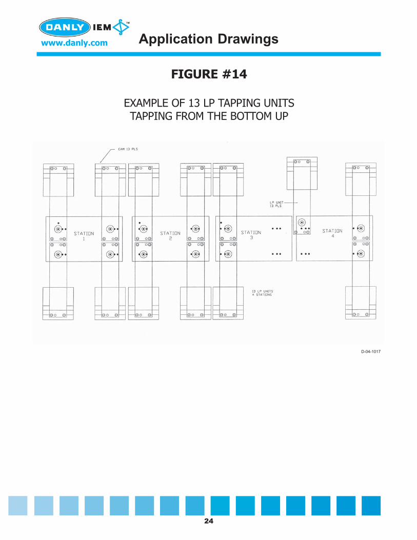
FIGURE #14
EXAMPLE OF 13 LP TAPPING UNITSTAPPING FROM THE BOTTOM UP
D-04-1017
Application Drawings
25
www.danly.com
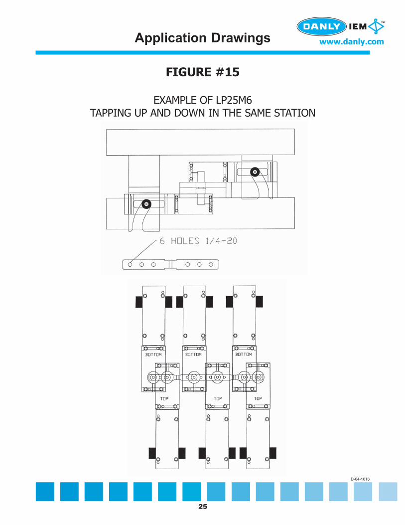
FIGURE #15
EXAMPLE OF LP25M6TAPPING UP AND DOWN IN THE SAME STATION
D-04-1018
Application Drawings
26
www.danly.com
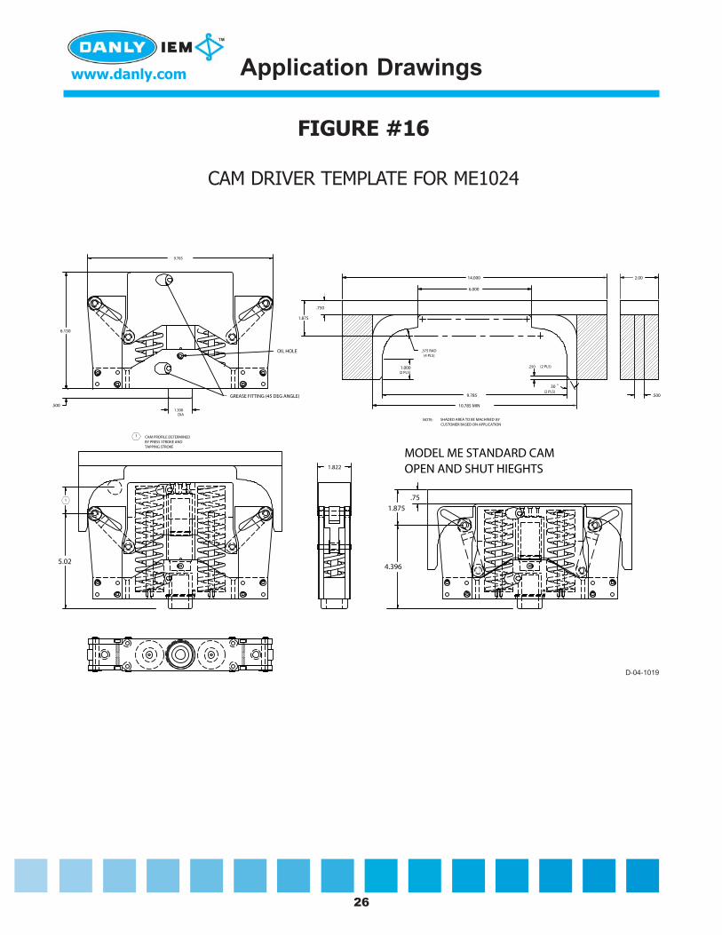
FIGURE #16
CAM DRIVER TEMPLATE FOR ME1024
1
CAM PROFILE DETERMINEDBY PRESS STROKE ANDTAPPING STROKE
1
MODEL ME STANDARD CAMOPEN AND SHUT HIEGHTS
5.02
.75
1.875
4.396
9.785
6.150
.500
.375 RAD(4 PLS)
6.000
14.000
.750
1.875
1.000(2 PLS)
(2 PLS)
10.785 MIN
9.785
30(2 PLS)
2.00
.500
CAM TEMPLATE FOR ME1024
1.300DIA
.250
SHADED AREA TO BE MACHINED BYCUSTOMER BASED ON APPLICATION
NOTE:
1.822
GREASE FITTING (45 DEG ANGLE)
OIL HOLE
D-04-1019
Application Drawings

27
www.danly.com
FIGURE #17
ME1024 CAMFIXED DIMENSIONS
.375 RAD(4 PLS)
.750
1.000(2 pls)
(2 pls)
9.785
30(2 pls)
.250
11.000
MATERIAL: 7075-T6 ALUMINIUM
FINISH: NONE
ENGRAVE JOB NUMBER
.375 RAD (2 pls)
14.000
R 1.000 (4pls)
6.000
1.0000
.6250 DIA
7.0000
1.875
.6000
2.00
D-04-1021
Application Drawings

28
www.danly.com
FIGURE #18
ME1024 CAMON BRIDGE STRIPPER
MATERIAL GUIDES
DIE PLATE
MATERIAL STRIPBRIDGE STRIPPER
DIE SPRING
GUIDE PINS
SPRING LOADED
.630 CLEARANCE HOLE FOR DRIVE SCREW
D-04-1022
Application Drawings

29
www.danly.com
FIGURE #19
CAM DRIVER MOUNTING FOR ME1024 CAMUSING A SPRING STRIPPER
1.00
END USER BASED ON PROPER HEIGHT REQUIREMENTS.
MATERIAL
DIE
THIS SECTION IS REMOVED BY
SPRING TRAVEL IS BASE ON TAPPING STROKE, PLUSPRELOAD ON MATERIAL BEFORETAPPING.
THIS DIM. IS THE SAME FORALL CAM`S, WHEN USED IN ASPRING STRIPPER APPLICATION.SUBTRACT AMOUNT OF PRELOAD TRAVEL USED BEFORE TAPPINGFROM THIS 1.00 DIM. IN MOST CASESUSE .05 TO .100 OF PRELOAD TRAVEL.
THIS WILL INSURE PROPER STRIPPINGFOR TAPPING.
MICRO SWITCH
CAUTIONIF USING A SPRING STRIPPER.
THAT THE STRIPPER COMES DOWN 100%. IF STRIPPERDOES NOT COME DOWN ALL THE WAY THE UNIT
TO BREAK.
THERE SHOULD BE A SENSOR TO MAKE CERTAIN
COULD BOTTOM OUT, CAUSING THE CAM ROLLER
D-04-1023
Application Drawings

30
www.danly.com
FIGURE #20
MOUNTING THE ME1024 UNIT IN A HYDRAULIC PRESS
OPEN
.625 DIA X 1.35 DEEP RELIEF HOLE IN PUSH BLOCK FOR SCREW
1.250 .100 MINIMUMTHIS KEEPS PUSHERBLOCK FROM MAKINGCONTACT ON CAMPLATES.
CAM PLATE
CLOSED
D-04-1024
Application Drawings
31
www.danly.com
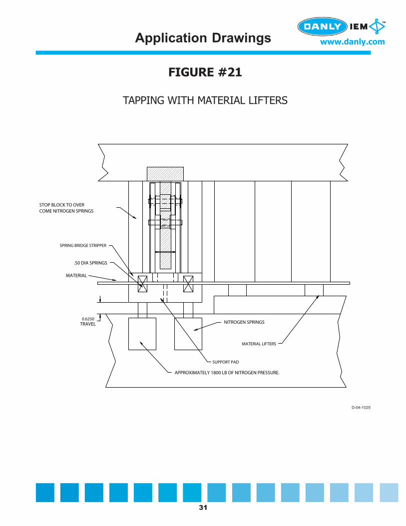
FIGURE #21
TAPPING WITH MATERIAL LIFTERS
NITROGEN SPRINGS
.50 DIA SPRINGS
MATERIAL
STOP BLOCK TO OVERCOME NITROGEN SPRINGS
0.6250
MATERIAL LIFTERS
SUPPORT PAD
SPRING BRIDGE STRIPPER
APPROXIMATELY 1800 LB OF NITROGEN PRESSURE.
TRAVEL
D-04-1025
Application Drawings

32
www.danly.com
FIGURE #22
SAMPLE LAYOUT FOR MULTIPLE TAPPINGWITH 3 ME1024 UNITS IN ONE DIE
AIR FEEDERAIR CLAMP
ME1024 TAPPING UNITS.
22.9537
48.6781
16.0000
4.1250 4.1250
NOTE: ALL DIMENSIONS ARE APPROXIMATE
D-04-1026
Application Drawings

33
www.danly.com
FIGURE #23
TYPICAL WAY OF APPLYING TAPPING UNITS TO IN-DIE TAPPING
DIE
BOTTOM DIE SET
PARALLEL
FIRST HOLE
SECOND HOLETAPPED
THIRD HOLETAPPED
TAPPED
PUNCH HOLESFOR TAPPING
PART
MACHINED POCKET
TAPPING UNITS 1,2,3
THREE HOLESTAPPED 10-32
PART PUNCHED OUT
THIS DIM. IS FROM THE TOPOF THE MATERIAL OR EXTRUSIONTO THE TOP OF THE CAM
6.271
2.00
5.00
.600
2.00
3.00
5.00
1.00
THIS DIE HAS ONEMACHINED POCKET
FOR ALL TAPPINGUNITS
12.103
IN THE CLOSED POSITION
MOUNTING SCREWSFOR CAM
.771
9.300
3/8-16 S.H.C.S
MATERIAL
D-04-1027
Application Drawings

34
www.danly.com
FIGURE #24
SUB-PLATE FOR LP25M6
1/2-20
1/4-20
SUB-PLATE
STOP BLOCK
GUIDE RAIL
GUIDE RAIL
D-04-1031
Application Drawings
35
www.danly.com
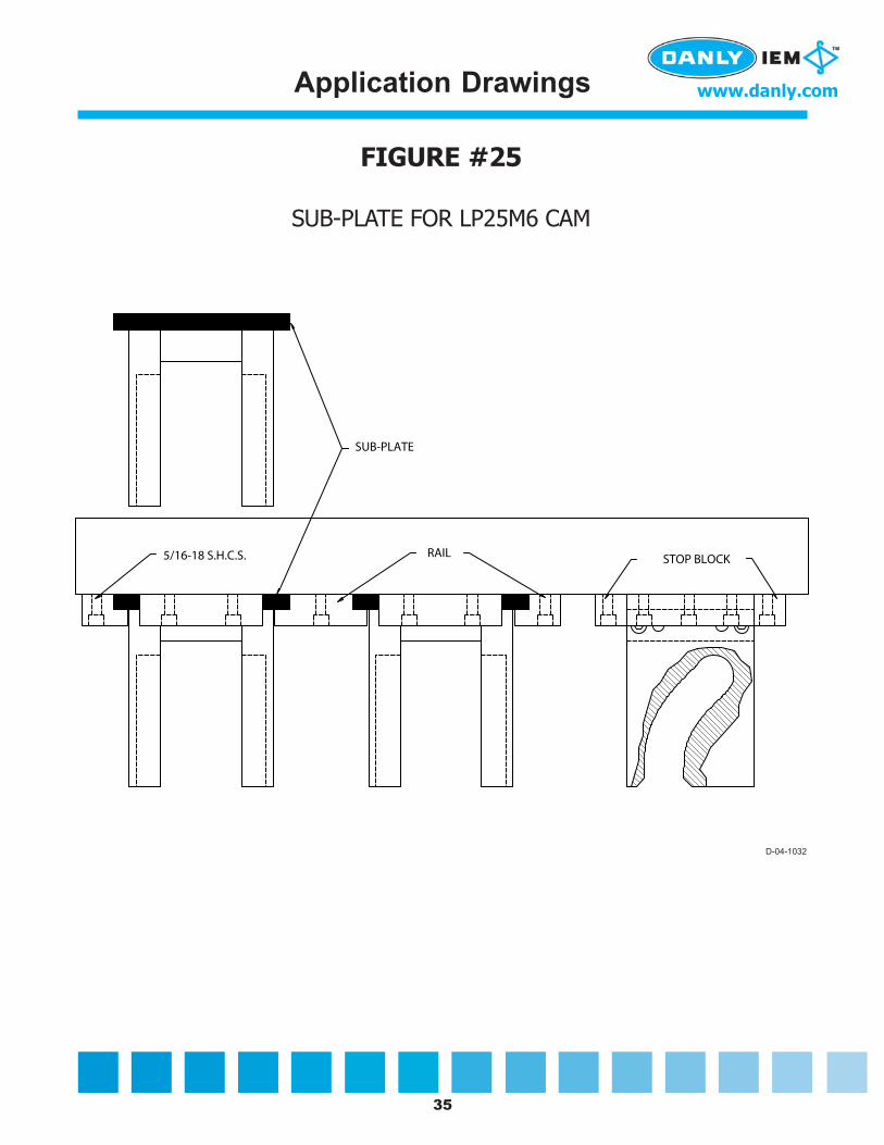
FIGURE #25
SUB-PLATE FOR LP25M6 CAM
SUB-PLATE
RAIL STOP BLOCK5/16-18 S.H.C.S.
D-04-1032
Application Drawings

36
www.danly.com
FIGURE #26
SUGGESTED LAYOUT FOR TAPPING BOTTOM UPWITH LOW PROFILE TOOLS AND USING A SUB DIE
DIE IN OPENPOSITION
DIE IN CLOSED POSITION
D-04-1033
Application Drawings

37
www.danly.com
FIGURE #27
LP25M6 MOUNTED ON A SPRING STRIPPER
STOP BLOCKS OR NITROGENSPRINGS TO OVER RIDE3,000 LBS OF SPRINGPRESSURE.
APPROXIMATIELY 3,000 LBSOF SPRING PRESSURE.
MATERIAL LIFTER
FORMING TRAVEL
D-04-1034
Application Drawings

38
www.danly.com
(Models ME1024 and LP25M6 only)
1. TOOL MODEL: ME1024 _______________ LP25M6 _______________
2. STROKE OF PRESS: _______________
3. TAPPING STROKE: _______________
The remaining stroke left after the material has advanced in its progression. Example: If a6" stroke press requires 2" to advance or progress, the tapping stroke would be (6" - 2") = 4".
4. SPEED OF PRESS IN STROKES PER MINUTE: _______________
5. TOTAL THICKNESS OF MATERIAL (include extrusion if applicable): _______________
Material thickness must include the gap between the tip of the tap and the top of material orextrusion. (Failure to do so could cause improper tap penetration.) (See Figure #15.)
6. MATERIAL TYPE: _______________
7. TAP SIZE: _______________
Designing a Cam Driver
39
www.danly.com
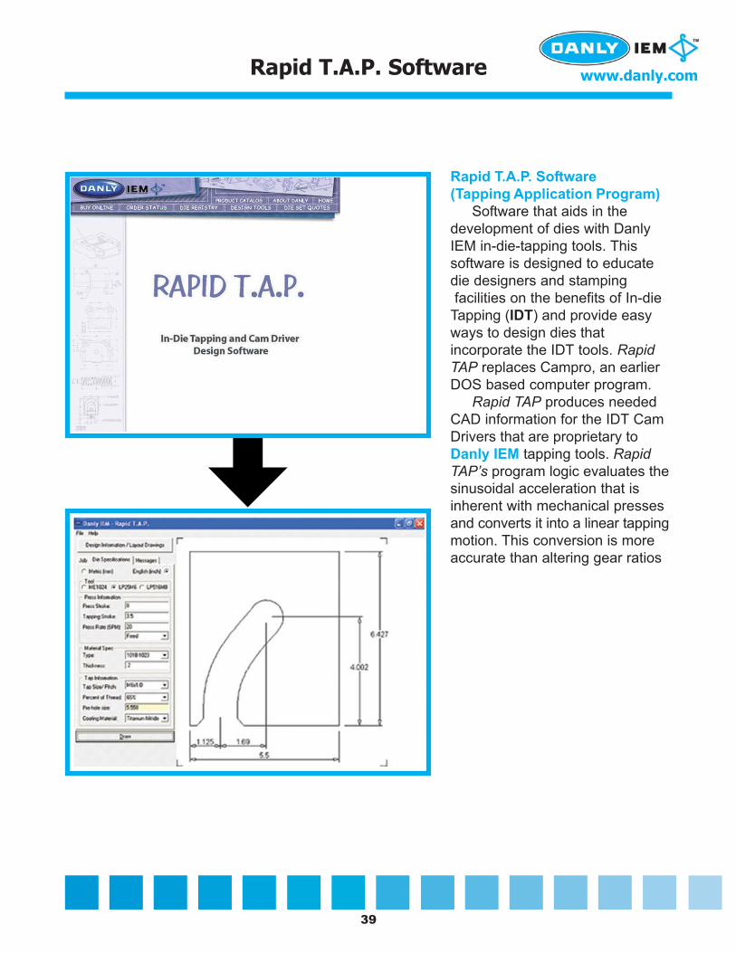
Rapid T.A.P. Software(Tapping Application Program)
Software that aids in thedevelopment of dies with DanlyIEM in-die-tapping tools. Thissoftware is designed to educatedie designers and stamping facilities on the benefits of In-dieTapping (IDT) and provide easyways to design dies thatincorporate the IDT tools. RapidTAP replaces Campro, an earlierDOS based computer program.
Rapid TAP produces neededCAD information for the IDT CamDrivers that are proprietary toDanly IEM tapping tools. RapidTAP’s program logic evaluates thesinusoidal acceleration that isinherent with mechanical pressesand converts it into a linear tappingmotion. This conversion is moreaccurate than altering gear ratios
Rapid T.A.P. Software

40
www.danly.com
1. DISTORTED THREADS
Threads are distorted and the go-gage will not go into the tapped hole. Check to see if anyportion of the die is hitting the top of the threads, such as the stripper plate, form block ora hold-down form pad. If this is the case, provide clearance for the hole by grinding ormachining a counter bore.
2. TAP BREAKS ON EVERY HIT
Make sure the hole is the correct size for a metal forming tap. If you are using a hole sizerecommended for a cutting tap, it is too small and will result in tap breakage. Ensure that thehole is being registered properly beneath the tap. See Mounting Procedures in the installationmanuals. For recommended pre-hole sizes, refer to the tables on pages 9 and 10 of thismanual.
3. TAP BREAKS AFTER ONE TO FIVE HITS
Tap height may be misadjusted and stocking out below the nose piece or boss. This conditionoften results in the tap catching on the material as at advances.
4. TAP BREAKS PREMATURELY
Check the lubrication. A discolored or black tap indicates that an improper level nor type oflubrication is being applied.
5. TAP SPINS BUT DOES NOT PENETRATE THE HOLE
The tap is backed up by a spring for “no hole” conditions. If this spring is weak there maynot be enough pressure to get the tap started. If a spring stripper or a spring loaded bridgestripper is used, adjust the tap so that is protrudes slightly from the nose piece. This will put apreload on the spring and increase spring pressure. If this does not correct the condition, astronger spring will have to be used. Call the factory for assistance if this is the case.
6. IF CHIPS ARE DEVELOPING
The pre-hole for the tap is too small. Opening up the hole by .002" to .003" will usually fixthe problem. Use 65% of thread to start with.
Trouble Shooting

© 2004 Danly IEM, A Division of Connell Limited Partnership DM109-1 8/04
6779 Engle Road Suite A - FCleveland, OH 44130-7926
VISIT US AT www.danly.comE-MAIL: [email protected]
TOLL FREE: 800.243.2659FAX: 800.833.2659