in cooperation with Newport News Shipbuildingare types of butt joint designs, two (2) of these are...
103
Weld Shrinkage Study U. S. DEPARTMENT OF THE NAVY CARDEROCK DIVISION, NAVAL SURFACE WARFARE CENTER in cooperation with Newport News Shipbuilding
Transcript of in cooperation with Newport News Shipbuildingare types of butt joint designs, two (2) of these are...

December, 1993NSRP 0397
Weld Shrinkage Study
U. S. DEPARTMENT OF THE NAVYCARDEROCK DIVISION, NAVAL SURFACEWARFARE CENTER
in cooperation with
Newport News Shipbuilding

Report Documentation Page Form ApprovedOMB No. 0704-0188
Public reporting burden for the collection of information is estimated to average 1 hour per response, including the time for reviewing instructions, searching existing data sources, gathering andmaintaining the data needed, and completing and reviewing the collection of information. Send comments regarding this burden estimate or any other aspect of this collection of information,including suggestions for reducing this burden, to Washington Headquarters Services, Directorate for Information Operations and Reports, 1215 Jefferson Davis Highway, Suite 1204, ArlingtonVA 22202-4302. Respondents should be aware that notwithstanding any other provision of law, no person shall be subject to a penalty for failing to comply with a collection of information if itdoes not display a currently valid OMB control number.
1. REPORT DATE DEC 1993
2. REPORT TYPE N/A
3. DATES COVERED -
4. TITLE AND SUBTITLE Weld Shrinkage Study
5a. CONTRACT NUMBER
5b. GRANT NUMBER
5c. PROGRAM ELEMENT NUMBER
6. AUTHOR(S) 5d. PROJECT NUMBER
5e. TASK NUMBER
5f. WORK UNIT NUMBER
7. PERFORMING ORGANIZATION NAME(S) AND ADDRESS(ES) Naval Surface Warfare Center CD Code 2230-Design Integration ToolsBldg 192, Room 128 9500 MacArthur Blvd, Bethesda, MD 20817-5000
8. PERFORMING ORGANIZATIONREPORT NUMBER
9. SPONSORING/MONITORING AGENCY NAME(S) AND ADDRESS(ES) 10. SPONSOR/MONITOR’S ACRONYM(S)
11. SPONSOR/MONITOR’S REPORT NUMBER(S)
12. DISTRIBUTION/AVAILABILITY STATEMENT Approved for public release, distribution unlimited
13. SUPPLEMENTARY NOTES
14. ABSTRACT
15. SUBJECT TERMS
16. SECURITY CLASSIFICATION OF: 17. LIMITATION OF ABSTRACT
SAR
18. NUMBEROF PAGES
102
19a. NAME OFRESPONSIBLE PERSON
a. REPORT unclassified
b. ABSTRACT unclassified
c. THIS PAGE unclassified
Standard Form 298 (Rev. 8-98) Prescribed by ANSI Std Z39-18
THE NATIONAL SHIPBUILDINGRESEARCH PROGRAM
WELD SHRINKAGE STUDY
SUBMITTED TO:
SHIP PRODUCTION COMMITTEEDESIGN/PRODUCTION INTEGRATION PANEL
BY
NATIONAL STEEL AND SHIPBUILDING COMPANYHARBOR DRIVE AND 28TH STREET
SAN DIEGO, CALIFORNIA

FOREWORD
The National Shipbuilding Research Program (NSRP) is a cooperative effort of the U.S.Navy and the United States shipbuilding industry. This report is the product of NSRPperformed for the Design/Production Integration Panel (SP-4) of whom W.G. Becker is theprogram manager.
This study will benefit the shipbuilding industry serving as a reference guide for shipyardengineers in the development of weld shrinkage factors. Shrinkage data collectionmethodology and statistical analysis is provided with the shrinkage factors derived, for eachstage of fabrication.
The project was performed by R. E. Doersksen, Assistant Welding Engineer, and directedby David L. Malmquist, Production Engineer, of the Steel Planning Department.Appreciation is expressed to Ken Coblentz, Staff Engineer, for initiation of the project andestablishing Shrinkage Collection Procedures, and also to those who assisted with laboratoryexperiments and data collection, especially A. D. Hunter, L. C. Swoboda, and A. A.Ramirez.


Inherent in the ship hull construction during assembly of interim products is weldshrinkage. Shipbuilder have recognized this fact and they realize the necessity ofplanning added material into the design phase to compensate for weld shrinkage. Thetraditional method to compensate for shrinkage has been to add excess material, usually1" of material on two sides of a block, that would be trimmed at the erection stage.Normally, this 1" of material would be adequate to compensate for any weld shrinkageincurred during block assembly. It is however, a commitment to rework.
Modern shipbuilders, employing New Construction Building Techniques, are attempting toeliminate this commitment to rework. By adding just enough material to compensate forweld shrinkage at each of the interim processes, a “neat” hull block can be built. In orderto accomplish this task, extensive data gathering of shrinkage at each interim process mustbe conducted. Results of the data gathering will then be analyzed and shrinkage factorsfor each of the interim processes will be developed. These shrinkage factors will then becommunicated to the Hull Engineering Department for inclusion into the detailed hull blockdesign.
Shrinkage factors for interim processes may vary from shipyard to shipyard due tofacilities, welding equipment, joint design, welding sequence, ambient temperature, andtype of material. Establishing and maintaining shrinkage factors is an investment shipyardsmake in improving productivity.
Through this study, the process of deriving shrinkage factors will be identified; from thedevelopment of check sheets, to establishing checking procedures, data gathering, and thestatistical analysis of data. Remembering that a variety of variables can effect thedetermination of a shrinkage factor, emphasis will be placed on the “How to” of theprocess.
1

1.0 INTRODUCTION
The process of determining shrinkage factors for three different stages ofconstruction is the task of this study. This can be accomplished by an extensivecollection of shrinkage data. The different stages of block assembly and erection arereferred to as interim processes. The three selected processes are plate panel buttshrinkage, hull block assembly shrinkage, and butt erection joint shrinkage.Through this study, the process and methods for gathering shrinkage data weredetermined for each of the interim processes.
Data collection sheets were specially formatted with all the necessary attributes andindependent variables that affect joint shrinkage. Shrinkage data was collected andorganized in data sets by the welding process and application. Included in eachsection is the statistical analysis of data and shrinkage factors derived.
1.1 INTERIM PROCESSES:
In the first interim process, shrinkage data was collected from panel butt joints.Weld shrinkage in the direction transversee to the butt joint was analyzed. Thesecond interim process, is the assembly stage, which consists of both longitudinaland transverse panel shrinkage data from stiffened panels. In this constructionstage fillet weld joint shrinkage data was analyzed. The third interim process,erection butt joint shrinkage data was collected for the various welding positions.Flow charts for each interim process page 6, 32, and 41 respectively illustrate thebreakdown of each interim process by the attributes of the welding environment.
Dimensional loss also results from weld shrinkage which causes angular distortionand panel buckling. The magnitude of these two types of distortion is limited withthe implementation and control of welding procedures.
1.2 DATA COLLECTION METHODOLOGY:
Collection of shrinkage data for the transveRSe butt joints required a measurementtechnique which would remain consistent throughout the project. The reliabilityprovided by a 200 mm digital caliper, as well as the ease in reading its display, madeit a logical choice for determining shrinkage dimensions. As permanent data pointswere established using a steel punch, repetitive checks were conducted, whichensured a tolerance of +/- .05 mm.

Data collection of hull block assembly shrinkage for the fillet weld joint design wasaccomplished with a tape measure in directions both longitudinal and transverse tothe direction of the welded stiffeners.
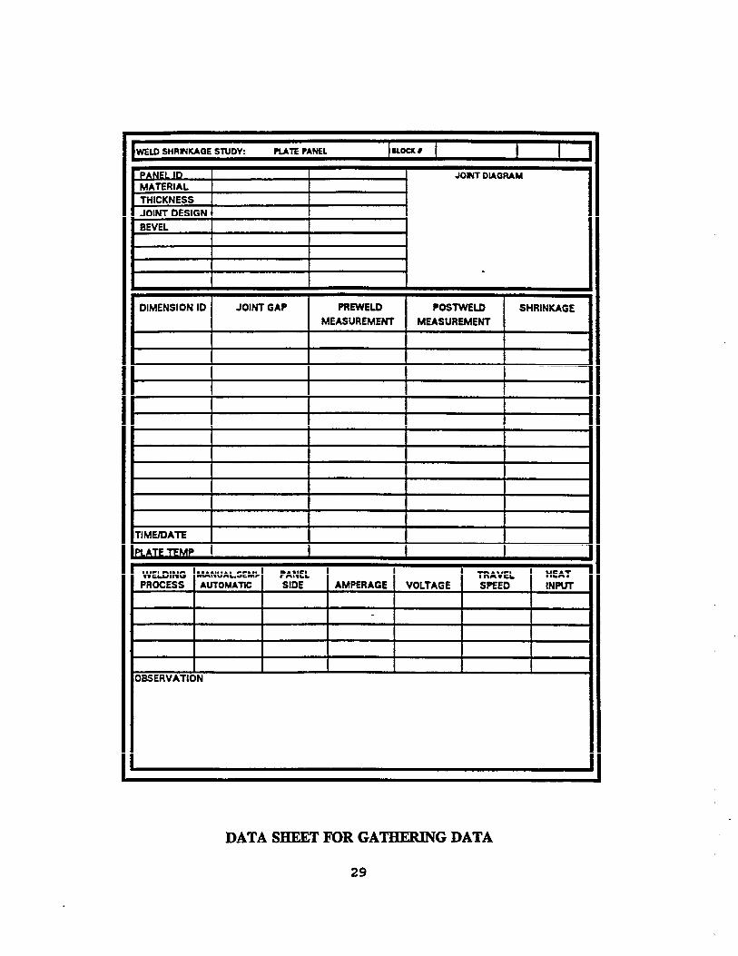
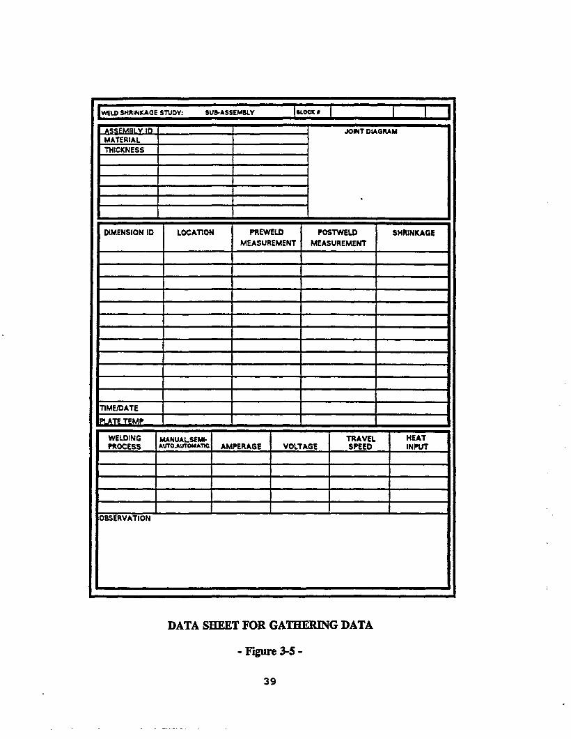
Data sheets were developed for the attributes that affect weld shrinkage. A sampleof the data sheets used in this study are displayed at the end of each section for eachinterim process (pages 29,39, and 84 respectively).
1.3
1.3.1 Butt Joint Shrinkage - Shrinkage data gathered for both the first and thirdinterim process was from a butt joint weld design. Pre-weld jointmeasurements were taken with a 200 mm caliper, in two punched marks,across the fitted joint (Figure 1-1).
General Measurement Diagram for Butt Joint- Figure 1-1.
3

At each weld joint, three (3) measurement locations were recorded. Theselocations were labeled Al, A2, and A3 for identification purposes, and alsofor identifying the direction of weld progression at the weld start, mid-length, and weld end locations respectively (Figure 1-2).
BUTT JOINTS
l DATA MEASUREMENT POINT
LOCATIONS FOR TRANSVERSE SHRINKAGE MEASUREMENTS
- Figure 1-2-
1.3.2 Assembly Shrinkage- Transvexse shrinkage measurements were taken witha tape measure placed through the stiffener rat holes adjacent to the paneledge. These measurements were recorded along with the number ofstiffeners, the material weight and independent variables.
Shrinkage measurements parallel to the stiffener direction were taken atthe outboard edge and recorded together with the distance from the closestpositioned stiffener. Panel shrinkage in this direction is a result oflongitudinal weld-metal contraction.
4

1.4 WELDING ATTRIBUTES:
Shrinkage data from each interim process was grouped by the following six weldingattributes. Knowledge of each of these attributes is important to understanding themechanisms that cause weld shrinkage. Changing any one of these attributes, wouldchange the characteristics indicative of the process that affect weld shrinkage. Asillustrated in the flow chart (Figure 1-3) for the first interim process, three jointdesigns, although all butt joints, are divided into three categories because eachaffects the mechanisms that cause weld shrinkage differently. The next attributedescribes the method of application or technique the welding process is utilized. Thefinal factor in distinguishing a weld shrinkage data set is the position of the joint.When the position of the joint changes, so do the welding heat input requirements.Of the welding attributes that are included in a shrinkge data set, the onlychanging attributes are material thickness and the independent variables. The rangeof material thickness is established for each data set, and all shrinkage data isorganized according to the material thickness of the joint.
Ž Joint Design
Ž Welding Process
Ž Method of Application
Ž Joint Position
Ž Material Thickness
Ž Independent Variables
5


1.4.1
1.4.2
1.4.3
1.4.4
1.4.5
JointDesign - Two (2) groups of joint designs were evaluated in this study.Shrinkage data is organized by these joint designs, butts and fillets. Thereare types of butt joint designs, two (2) of these are included in thisevaluation, square butt and V-groove joints.
Welding Process - Three (3) welding processes, SMAW (Shielded MetalArc Welding), FCAW (Flux-Cored Arc Welding), and SAW (SubmergedArc Welding) are the most common in ship hull production. There areapplications in which two (2) are used in combination. V-Groove ButtJoint designs are frequently welded with FCAW and SAW in combination.Weld shrinkage data was collected for each of these processes.
Method Of Application - Welding processes implemented are identified bythe type of power source (manual, semi-automatic, and automatic).Applications on backing versus no backing or one-sided welding versustwo-sided welding are examples of different application methods that areidentified among the common attributes of a shrinkage data set.
Joint Position - Shrinkage data was collected in either of three positions,flat, vertical or horizontal. Shrinkage data collected in the first andsecond interim processes was from the flat position and all three jointpositions in the third interim process. The overhead position was notoverlooked, but shrinkage factors for this position are not includedbecause of the limited collection of shrinkage data.
Material Weight - Shrinkage data is organized by material weight groups.See chart below for the corresponding relationship between materialweight and plate thickness.
WEIGHTS IN LBS PER MATERIAL THICKNESSSQUARE FEET (INCHES)
10.20 1/415.30 3/820.40 1/225.50 5/830.60 3/435.70 7/S40.80 145.90 11/8
-Figure 1-4-
7

1.4.6 Independent Variables - Factors that affect the degree of weld shrinkagewithin each interim process data set are the independent variables. Thesevariables change as a result of the working conditions and decisions madeby the welding operator. Each of these variables influence shrinkageindependently.
1.4.6.1
1.4.6.2
1.4.6.3
1.4.6.4
Welding Paramaters - From the welding parameters, voltage,amperage, and travel speed, the heat input of the weldingprocess is calculated. In several applications the weldingparameters are adjusted to specified settings by the weight ofthe material.
Joint Gap - This independent variable determines the weld sizefor a given material thickness. For a given joint design, theamount of weld metal required to fill the joint is determined bythis changing attribute.
Plate Temperature - The difference in base materialtemperatures recorded at the pre-weld measurement times andthe post-weld measurement times is critical for the secondinterim process. Thermal plate movement from ambienttemperature change, if not accounted for, can producedimensional changes that are as great as the weld shrinkage.To account for this plate expansion or contraction factor,allowances are provided depending upon the plate temperaturegradients (Figure 3-l). Block movement resulting fromambient temperature changes, is caused by thermal expansionand contraction. The pre-weld measurement of a butt jointcan shift through the day as a result of ambient temperaturechanges.
Restraint Conditions - The amount of weld joint shrinkage isdependant upon the level of joint restraint. Different forms ofrestraint counteract the shrinkage forces of a joint beingwelded. The most obvious form of joint restraint is created bythe joint fitting aids. For a V-Groove butt joint for example,reducing the number of strongbacks will lessen the restraintconditions creating more allowance for shrinkage.Experimental test results given in this report confirm thespread of weld shrinkage in restraint and no restraintconditions. In the third interim process them are other formsof restraint, more complex that also affect block movement orweld shrinkage.
8

2.0 FIRST INTERIM PROCESS - PLATE PANEL BUTT SHRINKAGE:
A welded butt joint between two (2) plates shrinks both transversely andlongitudinally changing the dimensions of the plate. Figure 2-1 illustrates these two(2) types of panel shrinkage, with shrinkage in the longitudinal direction causingpanel bowing, and shrinkage in the direction transverse to the welded joints causingloss of panel width. Transverse panel shrinkage is the cumulative shrinkage of allthe individual joints.
The panel bowing condition is not included in the report because loss to thelongitudinal panel edge length does not occur. Instead panel bowing is a localizeddistortion as indicated by the diagram.
PANEL ASSEMBLY SHRINKAGE
- Figure 2-1-
Transverse shrinkage was measured at three (3) typical locations along the jointlength. Shrinkage measurement locations were common for all of the jointsrecorded. Pre-weld measurement locations were placed at both ends of the joint,200mm from the panel edge and one (1) measurement at the mid-length of the joint.The pre-weld measurement was recorded together with the joint gap at eachlocation.
9

2.1 JOINT DESIGN - SQUARE BUTTS:
Among the butt joint designs used for assembly of plate panels, the most commonis the square butt. Square butt joints are welded with one process, Submerged ArcWelding, using two (2) methods of application. These methods are described as aone-sided welding application and a two-sided welding application (Figure 2-2).With both applications the joint position is flat. The range of material thicknessesfor the square butt joint design is limited and is indicated for each application.
SUBMERGED ARC WELDING
O N E - S I D E D
WELDING APPLICATIONS FOR SQUARE BUTT JOINTS
- Figure 2-2-
10

2.1.1 WeldingOne-Sided - One-sided describes the method of weldingapplication. With the panel joint positioned on a fluxed copper backingbar a full penetration weld is accomplished from one side of the joint, withone pass.
The full collection of shrinkage data from this method of weldingapplication is displayed in the histogram below (Figure 2-3). Thehorizontal axis represents the transverse shrinkage range with 0.20mm cellwidths and is labeled using the mid-points of each 0.20mm cell. Thenumber of transvee shrinkage measurements that fall within each cell isgiven by the frequency on the vertical axis. The most common transverseshrinkage measurement recorded for this process as the bar chartillustrates falls within the 1.00 mm to 1.20 mm cell. A total of 24shrinkage measurements fall within this range.
Before the spread of shrinkage is analyzed with respect to the independentvariables, the histogram provides a priliminary analysis of the magnitudeand range of data.
ONE-SIDED WELDINGSQUARE BUTT JOINT
10 .30 .50 .70 .90 1.10 1.30 1.50 1.70 1.90TRANSVERSE SHRINKAGE (mm)
PLATE PANEL BUTT SHRINKAGE
- Figure 2-3-
11

Thickness - The data tables of shrinkage measurements groupedby material weight are given on pages 18 and 19. The mean shrinkageand standard deviation is computed for each material weight group. Notein each case that the standard deviation computed is less than the standarddeviation calculated from the full data set. Material weights greater than22.90 lbs were not fabricated with this process, at the time of this study.
Before analysis of the independent variables, shrinkage variability isexamined to determine the relative shrinkage levels at each of the threejoint locations. The three joint locations shrinkage data represents are theWeld Start, Mid-Length, and Weld End Locations. The spread of meanshrinkage calculated for each joint location is illustrated in Figure 2-4, byeach material weight group. If data bases of equal and sufficient sizeswere available for each material weight group, a standard deviation ofequivalent proportions would provide a realistic comparison of theshrinkage spread at the three joint locations.
This graph illustrates greater shrinkage values at the mid-length locationof the joint, but this pattern is not typical of joints that have no pre-weldjoint gap (pages 18 and 19). Joint shrinkage with gaps 0.5mm and less inthe 10.20 lb. data set does not fluctuate between locations more than
12

FLAT PANEL SQUARE BUTTS
MEAN TRANSVERSE SHRINKAGE BYMATERIAL WEIGHT GROUPS AND JOINT LOCATION
Independent Variables - Understanding the causes of the shrinkagevariability within the data set, continues by the breakdown ofshrinkage data according to the independent variables of the weldingprocess.
The welding heat input is one independent variable that can bechanged by individual joint. With this one-sided process, the heat-input is set based on the material thickness being welded. The heat-input does not change randomly but remains in a fixed range.
Another independent variable is the pre-weld joint gap whichdetermines the weld joint area for a given material weight group(Figure 2-5). Each location where pre-weld shrinkage data wasgathered, the joint gap was registered at typical levels of 0 and 0.5millimeters. Two (2)and three (3) millimeter root gaps were excessiveand uncommon for material weights below 22.90 Ibs..
13

FLAT PANEL SQUARE BUTTS
10.20 15.30 20.40 22.90Material Weight (Ibs)
JOINT GAP TO 0.5mm JOINT GAp ABOVE o.5mmo
TRANSVERSE SHRINKAGE PER JOINT ROOT GAP
- FIGURE 2-5-
Transverse shrinkage is small and seemingly insignificant, but whenconsidering the number of plates per panel, the transverse shrinkageof butts becomes cumulative. In Figure 2-6 the cumulative jointshrinkage calculated from each of the panel butts is shown for theWeld Start, Mid-Length, and Weld End Locations. The shrinkage ofeach location is identified by a letter and number.
14

Method of Application
Automatic. One sided Weldingwith Fluxed Copper Backing Bar
Position of Welding
Flat
Material Weight (lbs.)
10.20
Independent Variables
Heat InputJoint gap
T r a n s v e r s e S h r i n k a g e ( m m )
LOCATION A+ B+ c + D+ E =Weld Start - 1 0.56 0.50 0.76 0.80 0.41Mid-Length- 2 0.84 0.76 1 .04 3.03
1.07Weld End -3 0.43
0.70 4.410.53 0.61 1.06 0.50 3.15
CUMULATIVE SHRINKAGE OF PANEL JOINTSBY EACH LOCATION
-Figure 2-6-
l
Regression Analysis - Analysis of the independent variables and their effects on weldshrinkage is apparent through a multiple regression of data. Regression is a measurementof how different factors relate to each other with a group of numbers that represent thenumeric relationships between the variables. Here the relationship of the independentvariables (factors) with the dependent variable, weld shrinkage is analyzed.
INDEPENDENT VARIABLESI
DEPENDENT1 VARIABLE
JOINT LOCATION MATERIAL WEIGHT (mm) JOINT GAPSHRINKAGE 4
15

The first independent variable is included to identify the location at which the shrinkagemeasurement was recorded, either of three locations, weld start, mid-length, or weld endlocations*
The next variable in the regression analysis is the material weight group which representsone of the joint sizes, either 10.20 lbs., 15.30 Ibs., 20.40 lbs., or 22.90 lbs..
One variable shown, the joint gap, is consistently 0.5mm or less with exception of the 22.90lb. group. This size of joint gaps were most consistent in this range, so the variable is notincluded in the regressions.
The welding heat input (calculated from the welding parameters) is not included becausethis variable is adjusted to a specified setting based on the weight of material. Thisvariable is changed relative to the weight of material only and so is not needed in theregression.
ONE SIDED WELDING REGRESSION RESULTS:
054001Ž 024334Ž RSquared = 034640Ž Number of Observations- = 73Ž Degrees of Freedom = 70
MATERIAL JOINTTHICKNESS LQCATION
Ž X Coefficient = 0.03345 -0.0267Ž Standard Errorof Coefficient = o.005634 0.03477
Using these regression results the predicted shrinkage factor is given for the material weightthickness groups.
16

ONE-SIDED SQUARE BUTT REGRESSION ANALYSIS
PREDICTED SHRINKAG
The predicted shrinkage of each material weight group is shown for the common jointgap sizes.
MATERIAL WEIGHT, 10.20 LBS.(All measurements in millimeters)
MATERIAL WEIGHT, 15.30 LBS
MATERIAL WEIGHT, 20.40 LBS.
MATERIAL WEIGHT, 22.90 LBS.
17


2.1.2 Two-Sided Welding - This welding application is described as two-sided because thepanel is turned to weld the second side. Unlike one-sided welding, full penetrationfrom one side is not required because full joint fusion will be achieved on the secondside. Only one welding pass is required for each side of the joint with no back-gouging.
Shrinkage data measurements are grouped in the respective cell widths anddisplayed in the histogram (Figure 2.7). The horizontal axis is Iabeled with the mid-points of each 0.20mm cell. The greatest frequency of shrinkage falls within the0.60 to 0.80mm cell range. The mean shrinkage and variability within the data setare shown below.
TWO-SIDED WELDINGSQUARE BUTT JOINT
TRANSVERSE SHRINKAGE (mm)
PLATE PANEL BUTT SHRINKAGE
- Figure 2-7-
20
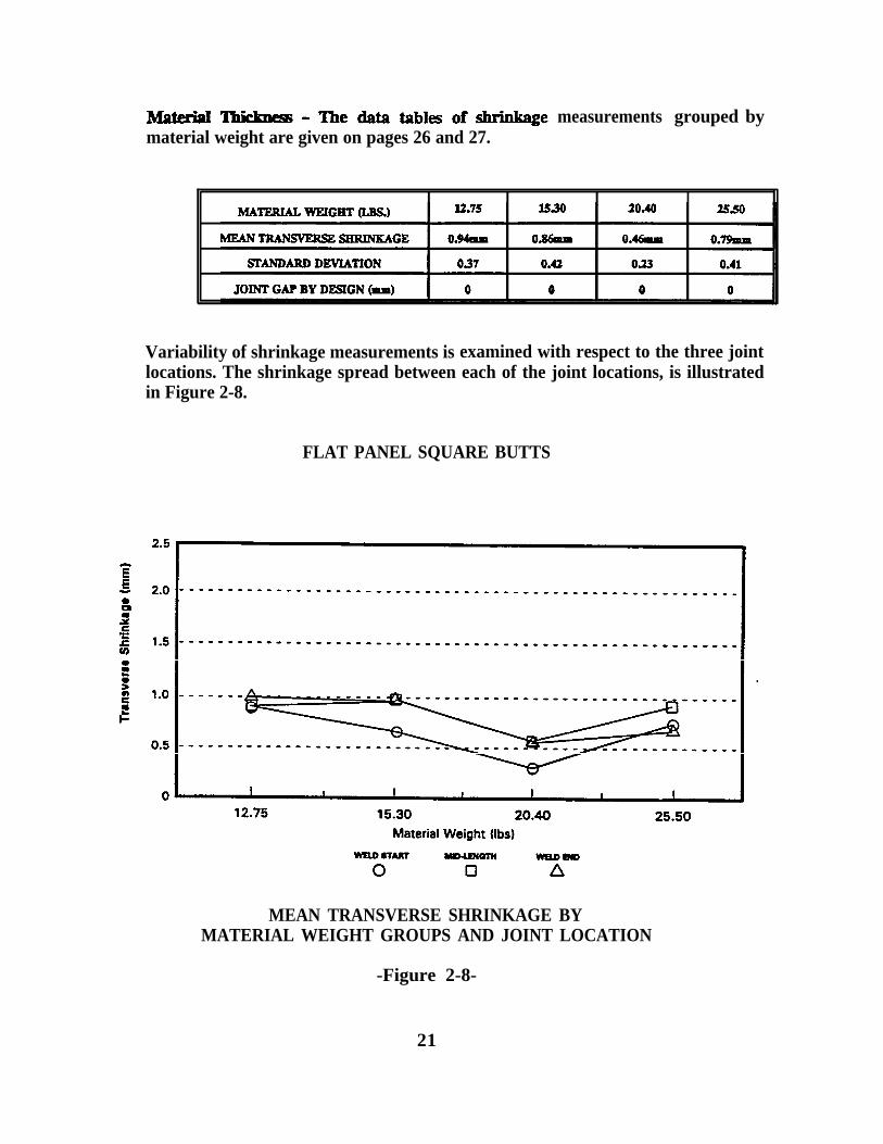
material weight are given on pages 26 and 27.measurements grouped by
Variability of shrinkage measurements is examined with respect to the three jointlocations. The shrinkage spread between each of the joint locations, is illustratedin Figure 2-8.
FLAT PANEL SQUARE BUTTS
MEAN TRANSVERSE SHRINKAGE BYMATERIAL WEIGHT GROUPS AND JOINT LOCATION
-Figure 2-8-
21

Independent Variables - The lower welding heat input characteristic of this processin comparison with one-sided welding produces lower base metal dilution. After thefirst side is welded, a restraint condition now exists against further shrinkage, whenthe second side is welded. This is in contrast with one-sided welding which is runwith higher heat inputs for a full penetration weld from one-side. The welding heat-input is again unique to each material weight group.
Unlike transverse shrinkage in one-sided welding, average shrinkage drops with theincreasing material weight groups. The decline in shrinkage is most evident for the20.40 lb. material. Correlation of the pre-weld joint gap with transverse shrinkageis analyzed (Figure 2-9) and the significance of this variable on transverse shrinkageis evident. Further analysis is required to study the effects of pre-weld gap onshrinkage levels at each material weight group.
FLAT PANEL SQUARE BUTT’S
12.75 15.30 20.40 25.50Material Weight (Ibs)
JOINT GAP TO 0.5mm JOINT GAP ABOVE 0.5mmo D
TRANSVERSE SHRINKAGE PER JOINT ROOT GAP
- Figure 2-9-
22

TIPLE REGRESS ON OF TRANSVERSE SHRINKAGE.I .
Regression Analysis-The same independent variables used for the one-sided regression areused here, with inclusion of the joint root gap.
Using these regression results the predicted shrinkage factor is plotted by the materialweight thickness groups using the average preweld joint gap from the data set roundedoff to the nearest millimeter. (Figure 2-10)
23


2.2 NORMAL DISTRIBUTION;.
All of the data for both the one-sided and two-sided square butt welding applicationshave been combined to form a complete set of shrinkage data for square butt jointwelding.
The data collected for this interim process, when displayed in the density functionmathematical model, takes the shape of a bell curve (Figure 2-11) with a 0.91 mm meanshrinkage and 0.39 standard deviation.
PERCENT AREA UNDER THE NORMAL DISTRIBUTION(THE X-AXIS SHOWS +/- 2 STANDARD DEVIATIONS)
SQUARE BUTT JOINT PANEL SHRINKAGEONE-SIDED AND TWO-SIDED
- Figure 2-11-
2.3 JOINT DE$IGN - V-GROOVE BUTTS:
There are applications for both single V-Groove and double V-Groove jointdesigns. The single V-Groove is welded with a one-sided application usingFCAW on ceramic tile followed with SAW for the fill and cover passes.
The double V-Groove welded with SAW is for a two-sided application.Shrinkage data for this application was not gathered, because there was not asufficient number of panels to explore these joint designs.
The experimental study of this report does evaluate single V-Groove buttshrinkage, and the range of shrinkage by material weights is evident. V-Groovebutt joint shrinkage is included in the third interim process.
28

3.0 SECOND INTERIM PROCESS: HULL BLOCK SHRINKAGE
In this process distortion which results from fillet welding stiffeners to panels isanalyzed. Panel shrinkage was measured along the panel edge, in directions bothlongitudinal and transverse to the direction of welded stiffeners. It was notalways possible to collect shrinkage data with one common dimension, soshrinkage data is provided with the estimated shrinkage per five (5) meter length.
In the longitudinal stiffener direction the location of the nearest stiffener to thepanel edge will produce longitudinal shrinkage. Weld shrinkage in this directionand subsequent 10SS to panel length is more difficult to determine because of thebowing condition. The areas that have the least bowing, that is the leastshrinkage, must be considered together with the other bowed areas.
Taken into consideration with weld shrinkage in the transverse direction was thenumber of fillets and leg size of welds per measured length. The tuckingallowance or out-of-plane distortion is not considered in the measurement ofshrinkage in this study. This type of distortion as mentioned earlier, can becontrolled by proper welding procedures.
AMBIENT PLATE TEMPERATURE - Thermal plate expansion results fromincreasing ambient temperature. When determining transverse and longitudinalshrinkage from pre-weld and post-weld measurements, ambient temperatures atboth times must be recorded. The dimensional changes resulting from ambienttemperature can be as great or greater than the actual weld shinkage. Theopportunities for post-weld measurements were during times the ambienttemperature difference was as high as 25 degrees. The coefficient of linear plateexpansion was used with calculation of panel shrinkage whenever there was athermal gradient between measurements. The linear plate expansion chart isgiven as a reference to the levels of expansion/contraction units, which were usedin the adjustments of all data (Figure 3-1).
30

- FIGURE 3-1-
3.1 JOINT DESIGN - FILLER
The common joint design used in hull block assembly is the fillet joint. The filletweld is utilized to join materials on the panel surface. Stresses are created onone side of the panel, which induce panel distortion, resulting from transverseand longitudinal panel shrinkage. This joint design must be distinguished fromfull penetration T-Joints not included in the evaluation. The flow chart (Figure3-2) illustrates the breakdown of the 2nd Interim Process.
31

3.2 WELDING PROCESSES AND METHODS OF APPLICATION:
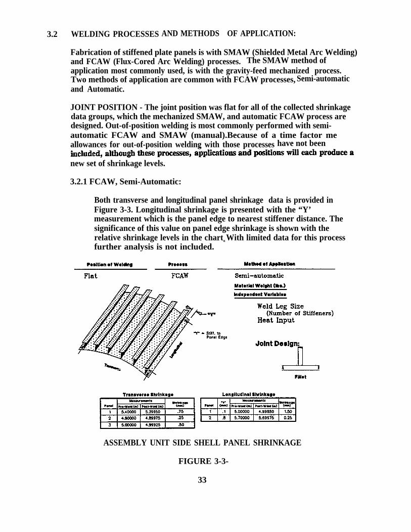
Fabrication of stiffened plate panels is with SMAW (Shielded Metal Arc Welding)and FCAW (Flux-Cored Arc Welding) processes. The SMAW method ofapplication most commonly used, is with the gravity-feed mechanized process.Two methods of application are common with FCAW processes, Semi-automaticand Automatic.
JOINT POSITION - The joint position was flat for all of the collected shrinkagedata groups, which the mechanized SMAW, and automatic FCAW process aredesigned. Out-of-position welding is most commonly performed with semi-automatic FCAW and SMAW (manual).Because of a time factor meallowances for out-of-position welding with those processes have not been
new set of shrinkage levels.
3.2.1 FCAW, Semi-Automatic:
Both transverse and longitudinal panel shrinkage data is provided inFigure 3-3. Longitudinal shrinkage is presented with the “Y’measurement which is the panel edge to nearest stiffener distance. Thesignificance of this value on panel edge shrinkage is shown with therelative shrinkage levels in the charto With limited data for this processfurther analysis is not included.
ASSEMBLY UNIT SIDE SHELL PANEL SHRINKAGE
FIGURE 3-3-
33

3.2.2
Independent Variables - The 2nd Interim Process was evaluated togetherWith these variables.
Weld Leg Size : 6.3mm (1/4”) (joint Gap=O)Heat Input: This variable is cosistent with in the data set.Ambient Plate Temperature Thermal gradient
SMAW, Mechanized:
Transverse shrinkage was recorded together with the number of Stiffenersto identify the number of welds per measured length. The shrinkage dataset (page 38) provides panel shrinkage in this direction per 5m and thislength covers seven (7) Stiffeners.
Longitudinal panel edge shrinkage is dependent upon the proximity of thenearest stiffener to the edge. So allowances for shrinkage must also bebased upon this distance.
Figure 3-4 illustrates a typical panel with the attributes identified below,for the transverse and longitudinal panel shrinkage.
— Panel Assembly —


INDEPENDENT VARIABLES - The fillet weld leg size of 6.3mm (1/4") isa consistent variable in the shrinkage data set. Consistency of applicationis critical to maintaining this leg size. Leg sizes of 3/16” and 5/16"represent a significant size change and must be analyzed by theirrespective sizes. Leg sizes will also vary as a result of joint gap, butstiffeners were fit tight under normal conditions.
The weld heat-inputs for each process are not included, because thisremains in a freed range dependent upon the size of consumable, and sizeof weld. The size of consumable was consistent for each panel welded, sothe heat input variable remained constant.
Three panels are described here with longitudinal shrinkage results for thenearest stiffeners located at .4m, .7m, and l.lm from the panel edge. Atan edge distance of .4m the longitudinal shrinkage was 1.25mm, but whenthis distance changed to .7m and l.lm the panel shrinkage was only0.25mm.
3.2.3 FCAW, Automatic:
This stiffener welding process is continuous and two-sided (dual-headed).The term continuous refers to the welding application which is continuous,from the start to the end of the joint. The semi-automatic method is notcontinuous because the operator must start and stop the weldingapplication while proceeding along the joint.
The material weight is a significant attribute because the platetemperature cooling rates will vary by material weights. With a largerdatabase shrinkage data would be grouped by material weight size, buthere the shrinkage is analyzed for the full data set.
36

INDEPENDENT VARIABLES - The fillet weld leg size was 6.3 mm (1/4").
The weld heat-inputs for each process are not included, because thisremains in a fixed range dependent upon the size of consumable, and sizeof weld. The size of consumable never changed, and the heat inputremained constant.
With a greater volume of data, more accurate allowances for bothtransverse and longitudinal weld shrinkage could be made.
ASSEMBLY PANEL SHRINKAGE, FCAW AUTOMATIC
-FIGURE 3-6-
37


- ERECTION JOINT SHRINKAGE
This interim process encompasses the analysis of transverse shrinkage data collectedfrom the primary joints of an erected block unit. Each joint is distinguished by itsposition and the welding processes and applications implemented. The shrinkage datais classified by each joint type because the attributes of the data sets are unique.
Shrinkage measurement techniques used for gathering data were identical to thoseused for the f- interim process. Three pre-weld measurements were documentedfor each joint at the Weld Start, Mid-Length, and Weld End locations together withthe joint gap. Weld Start and Weld End measurement locations of erection jointswere placed.5 to 1.0 meters from the joint ends.
4.1 Joint Design - V-Groove Butts
The common weld joint design for this process, is the V-Groove Butt with a includedbevel angle of 45 degrees that is typically 22.5 degrees per plate and varies between 20and 25 degrees with no land. The joint bevel, material thickness, and the root gapare used in calculating the joint area. For the purposes of this study the joint bevel isnot included in the analysis as a variable because the bevel did not fluctuate morethan 10 degrees. By design the root gap is 6.3mm (1/4”) as shown in reference ofjoint design (page 97).
42 welding Processes and Methods of Application:
SMAW (manual) or FCAW (semi-automatic) welding processes or a combination ofboth are used for welding both vertical (shell butts) and horizontal (shell seams)joints. Fiat joints (deck seams or butts) were welded with a combination of processes,FCAW (semi-automatic) and SAW (automatic). The one-sided application on ceramicbacking was the focus of this study, however, a further study should also include thetwo (2) sided welding application. The flow chart (page 41) illustrates the breakdownof this interim process into shrinkage data sets by joint Position.
40
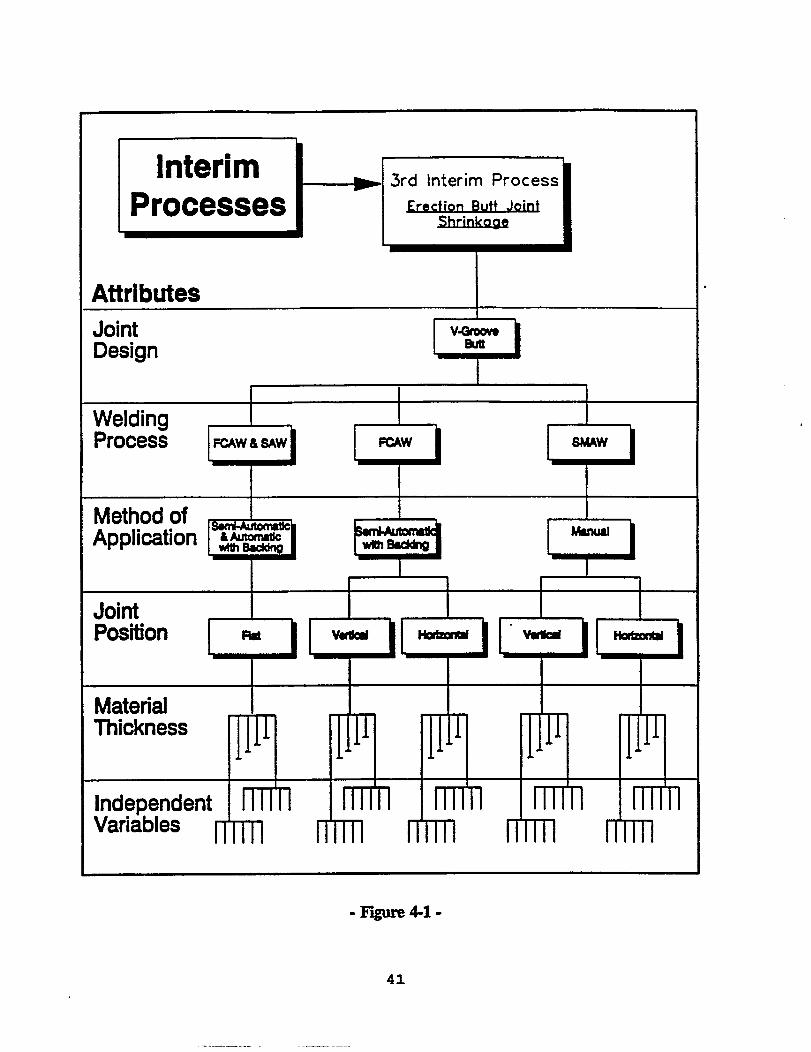

4.3 Joint Position:
The geometric positions of weld joints on two types of erection blocks are illustrated infigures 4-2 and 4-3. As a result of the varying degrees of restrtraint conditions,shrinkage from each type of block cannot be combined although the attributes mightbe the same. The shrinkage levels shown under each block diagram are an indicationof this.
The pre-weld measurements of the bottom shell block were taken with a 2002mmcaliper placed across the butt joint in two punch marks, at the location indicated.The same procedure was used after the joint was welded for the post-weldmeasurements. Shrinkage was calculated at each location from the difference of thesetwo measurements. The shrinkage data is not extensive for bottom shell blocks, dueto the stage of construction during the period of this investigation and is therefore notanalyzed separately with the shell block shrinkage data.
BOTTOM SHELL BLOCK WITH ATTRIBUTES AND JOINT SHRINKAGE DATA
-Figure 4-2-
42

ILLUSTRATION OF BLOCK WITH WELDING ATTRIBUTES
--SIDE SHELL BLOCK-
SIDE SHELL BLOCK WITH JOINT SHRINKAGE DATA
-Figure 4-3-
Figure 4-3 illustrates a side shell block and the four (4) joints with their respectiveattributes. Pre-weld and post-weld shrinkage data was taken using the sametechnique with 200mm caliper measurements transverse to the weld direction.
Each joint is classfied as its own data set for several reasons. The position of thejoint has different forms of outside restraint acting upon it. The types of restraintand spacing also vary. The welding processes and heat-inputs are not common amongall of the joint positions.
Side shell blocks are welded in sequence beginning with the shell butt followed byeither the shell seam or the deck butt.
43

Asummarized comparative view of block shrinkage organized by weld joint type isprovided in figure 4-4. The range and magnitude of weld shrinkage in each of thedata sets is illustrated by the mean values of shrinkage at each joint location and thestandard deviation of the full data set. A histogram is provided to show the frequencyof shrinkage as an overview which combines all of the weld shrinkage for this interimprocess. There is further analysis of the data sets by the attributes of the process, asit relates to shrinkage variance, in the following sections.
COMPARATIVE VIEW OF ERECTION JOINT SHRINKAGE DATA SETS BYWELD JOINT TYPE AND LOCATION ALONG THE JOINT LENGTH
-Figure 44-


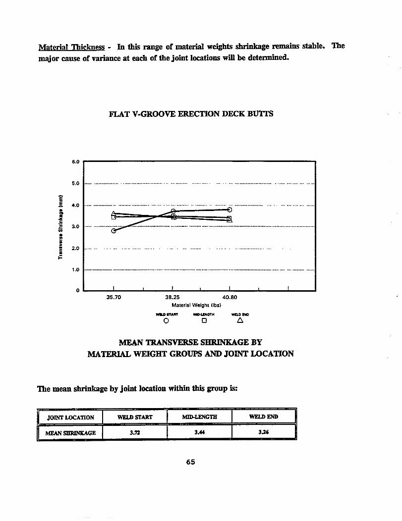
Material Thickness - The mean transverse shrinkage by material thickness is illustratedin the graph. The transverse shrinkage increases slightly with increasing materialthickness. The graph also shows the start location in each case has a lower amount oftransverse shrinkage than the remainder of the weld joints. This fact can be controlledthrough restraint and welding sequence or compensated for in the erection procedure.
VERTICAL V-GROOVE ERECTION SHELL BUTTS
47

INDEPENDENT VARIABLES:
increase in transverse shrinkage as the joint gap increases.
VERTICAL V-GROOVE ERECTION SHELL BUTTS
TRANSVERSE SHRINKAGE PER JOINT ROOT GAP
Joint Restraint Conditions - Typical restraint consisted of one sliptype stud fitting aidper three (3) feet.
Weld Heat Input - The welding heat input has not been considered as a variable in thisanalysis, because it was fairly consistent within the process studied. However, it is akey variable that must be included whenever there is a change in the welding process orthe weld procedure.
48

Multiple Regression of Transverse Shrinkage:
Transverse shrinkage is regressed by each material weight group per joint location, andaverage joint root gap equal to 7.5 mm.
Shrinkage increases significantly at the mid-length and weld end locations. Thiscondition can be controlled through outside restraint conditions and by modifying thewelding sequence. This is often compensated during the erection process by the erectionprocedure.
Predicted shrinkage is also regressed for 10.0 mm joint gaps less common in theshrinkage data set.
Regression Results:
PLOTTED REGRESSION OF PREDICTED SHRINKAGE
49


rial Thickness - Transverse shrinkage increases slightly at material weights above20.40 lbs. Within this data set the transverse shrinkage does not vary significantlyalong the joint location as with other joint positions.
HORIZONTAL V-GROOVE ERECTION SHELL SEAMS
MEAN TRANSVERSE SHRINKAGE BYMATERIAL WEIGHT GROUPS AND JOINT LOCATION
The mean shrinkage by joint location within this group is:
53

INDEPENDENT VARIABLES:
steadily with the joint root gap. Thejoint gaps of 5.Omm to 10.0mm area significant factor, causing almost lmm ofvariance.
HORIZONTAL V-GROOVE ERECTION SHELL SEAMS
Root Gap (mm)
TRANSVERSE SHRINKAGE PER JOINT ROOT GAP
Joint Restraint Conditions - Localized joint restraining g“ l devices control transverseshrinkage and are consistent in their implementation with this joint position. Thenumber of strongbacks was typically 20 per joint. This equated to one (1) weldedstrongback positioned 2’ to 2 1/2’ along each joint.
Weld Heat Input - The range of heat input is given in the shrinkage data set.
54

Multiple Regression of Transverse Shrinkage:
The independent variables included in the regression analysis are, material weight, jointlocation, and joint root gap. The calculated average root gap is equal to 7.5mm for20.40 lb., 22.95 lb. and 30.60 lb. groups. The average joint gap of 28.05 Ib material is5.Omm. The predicted shrinkage reflects the reduced joint size as shrinkage takes a dipat the 28.05 lb. material weight.
Regression results:
PLOTTED REGRESSION OF PREDICTED SHRINKAGE
55


Material Thickness - This graph of mean shrinkage decreasing as the material weightgroups increase illustrates an unusual shrinkage pattern. This condition is a result of thecomplex restraint variables surrounding the joints during the analysis, in addition, acombination of slip-type and welded strongbacks were used on various joints. Insight intothe effect of this combination is explained through subsequent tests perfomed underlaboratory condition provided in the following sections.
FLAT V-GROOVE ERECTION DECK BUTTS
MEAN TRANSVERSE SHRINKAGE BYMATERIAL WEIGHT GROUPS AND JOINT LOCATION
The mean shrinkage by joint location within this group is:
JOINT LOCATION WELD START I MID-LENGTH WELD END
MEAN SHRINKAGE 3.98 4.00 3.44
59

INDEPENDENT VARIABLES:
Joint Root Gap - This graph also illustrates an unusual decreasing shrinkage by joint rootgap. Other variables during the welding process not defined attributed to this decline. Asexplained in the previous section the complex condition caused by various types of externalrestraint are attributed to this trend.
FLAT V-GROOVE ERECTION DECK BUTTS (12.75, 15.30 AND 20.40 LBS)
5.0 7.5 10.0Root Gap {mm)
TRANSVERSE SHRINKAGE PER JOINT ROOT GAP
Joint Restraint ConditionS - Typical restraint conditions consisted of a combination of stud-fitting aids and use of welded strongbacks, in high restraint areas.
Weld Heat Input - The range of heat input is given in the shrinkage data set.
60

Multiple Regression of Transverse Shrinkage:
With the mean root gap of each material weight group equal to 7.5mm the results of theplotted regression illustrate this decrease in transverse shrinkage with increasing materialweight. Conclusions based on results like this cannot be given without further analysis ofthe effect of the joint restraint condition.
Regression results:
Predicted Shrinkage:
FLAT ERECTION DECK BUTTS (12.75, 15.30 AND 20.40 LBS)
PLOTTED REGRESSION OF PREDICTED SHRINKAGE
61

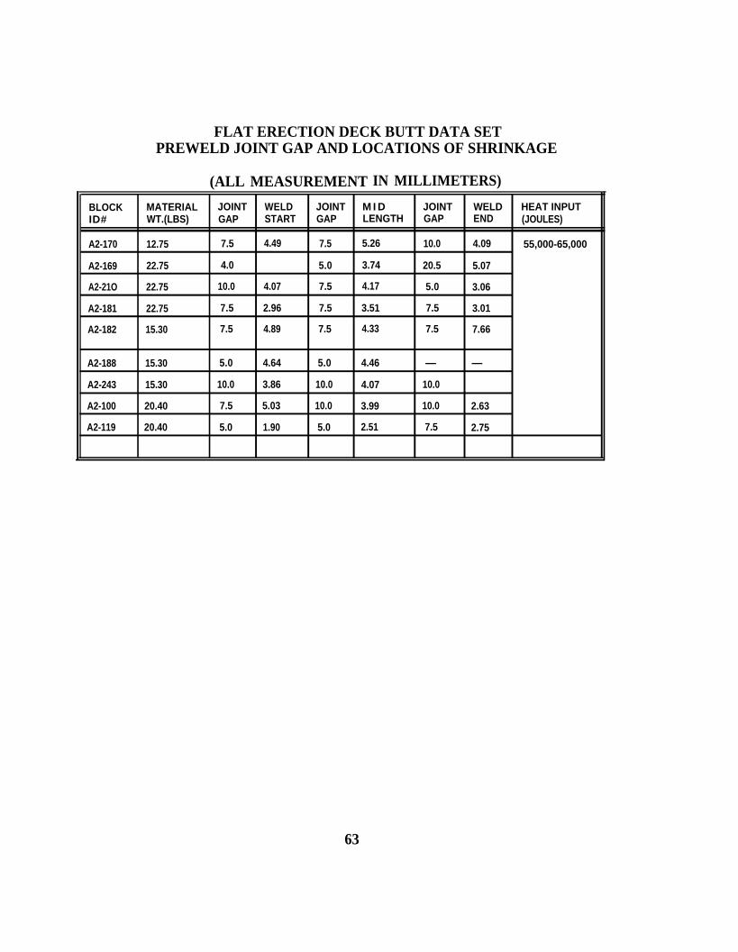
FLAT ERECTION DECK BUTT DATA SETPREWELD JOINT GAP AND LOCATIONS OF SHRINKAGE
(ALL MEASUREMENT IN MILLIMETERS)
BLOCK MATERIAL JOINT WELD JOINT M I D JOINT WELD HEAT INPUTID# WT.(LBS) GAP START GAP LENGTH GAP END (JOULES)
A2-170 12.75 7.5 4.49 7.5 5.26 10.0 4.09 55,000-65,000
A2-169 22.75 4.0 5.0 3.74 20.5 5.07
A2-21O 22.75 10.0 4.07 7.5 4.17 5.0 3.06
A2-181 22.75 7.5 2.96 7.5 3.51 7.5 3.01
A2-182 15.30 7.5 4.89 7.5 4.33 7.5 7.66
A2-188 15.30 5.0 4.64 5.0 4.46 — —
A2-243 15.30 10.0 3.86 10.0 4.07 10.0
A2-100 20.40 7.5 5.03 10.0 3.99 10.0 2.63
A2-119 20.40 5.0 1.90 5.0 2.51 7.5 2.75
63

4.3.3B FLAT DECK BUTTS: (GREATER THAN 20.4 LBS.)
COMMON WELDING ATTRIBUTES
JOINT DESIGN WELDING PROCESS METHOD OF APPLICATION JOINT POSITION
V-GROOVE FCAW/SAW SEMI-AUTOMATIC/ FLAT(45° INCLUDED) AUTOMATIC
. 2 5 . 7 5 1 . 2 5 1 . 7 5 2 . 2 5 2 . 7 5 3 . 2 5 3 . 7 5 4 . 2 5 4 . 7 5 5 . 2 5 5 . 7 5TRANSVERSE SHRINKAGE [mm)
SHRINKAGE HISTOGRAM OF ERECTION JOINTS
64

INDEPENDENT VARIABLES:
Joint Root Gap - The mean transverse shrinkage increases almost 1mm as the root gapincreases from 5.0mm to 10.0mmo
FLAT V-GROOVE ERECTION DECK BUTTS
5.0 7.5 10.0Root Gap (mm)
TRANSVERSE SHRINKAGE PER JOINT ROOT GAP
Joint Restraint Conditions - Typial restraint conditions consisted of a combination ofwelded strongbacks and slip-type stud fitting aids.
Weld Heat Input - The range of heat input is given in the shrinkage data set.
66


INDEPENDENT VARIABLES:
Joint Root Gap - This data set had only three (3) recorded pre-weld joint gaps not equalto 7.5mm so shrinkage by this variable is not analyzed.
Joint Restraint Conditions - Typical restraint conditions consisted of 10 to 20 slip-tight studfitting aids, positioned 2 1/2’ to 3’ apart.
Weld Heat Input - The range of heat input is given in the shrinkage data set.
72

Multiple Regression of Transverse Shrinkage:
One independent variable is not included uxlike the other erection joint regressions, thejoint root gap. The increase in shrinkage is a result of the increased 20.40 lb. materialjoint size.
Regression results:
Predicted Shrinkage:
FLAT ERECTION DECK SEAMS (15.30 and 20.40 LBS
PLOTTED REGRESSION OF PREDICTED SHRINKAGE
73


Material Thickness - Shrinkage levels are very close with respect to thematerial group range. The charts indicate mean shrinkage at each of thejoint locations is not influenced significantly by the material weight, but isinfluenced by the joint gap variance as shown in the subsequent graphs.
FLAT V-GROOVE ERECTION DECK SEAMS
MEAN TRANSVERSE SHRINKAGE BYMATERIAL WEIGHT GROUPS AND JOINT LOCATION
The mean shrinkage by joint location within this group is:
77
INDEPENDENT VARIABLES:
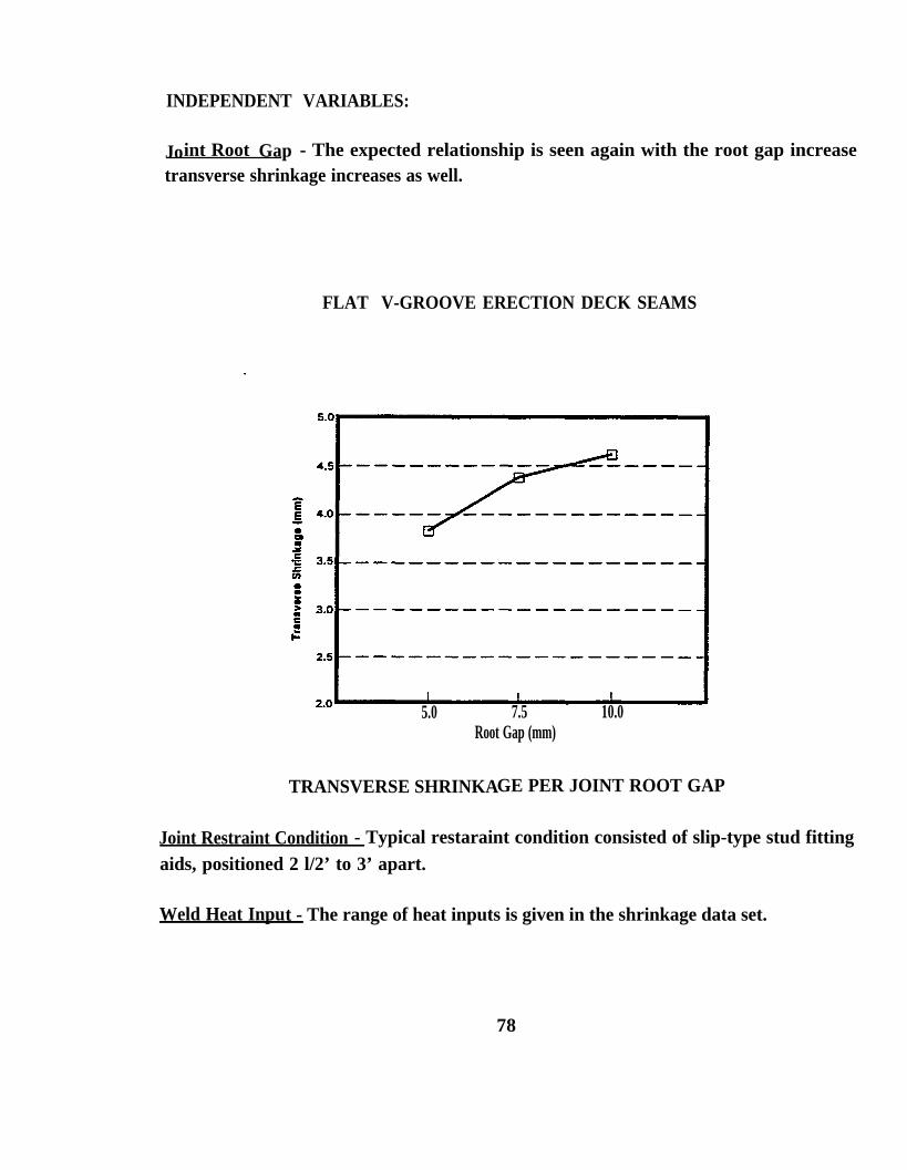
Joint Root Gap - The expected relationship is seen again with the root gap increasetransverse shrinkage increases as well.
FLAT V-GROOVE ERECTION DECK SEAMS
5.0 7.5 10.0Root Gap (mm)
TRANSVERSE SHRINKAGE PER JOINT ROOT GAP
Joint Restraint Condition - Typical restaraint condition consisted of slip-type stud fittingaids, positioned 2 l/2’ to 3’ apart.
Weld Heat Input - The range of heat inputs is given in the shrinkage data set.
78

Multiple Regression of Transverse Shrinkage:
Shrinkage levels are very consistent when considering the 7.5mm mean joint gap. In the38.25 lb material grouping transverse shrinkage increases as expected with the mean rootgap of 100mm.
Regression results:
Predicted Shrinkage:
FLAT ERECTION DECK SEAMS (35.70, 38.25, 40.80 AND 45.90 LBS)
PLOTTED REGRESSION OF PREDICTED SHRINKAGE
79


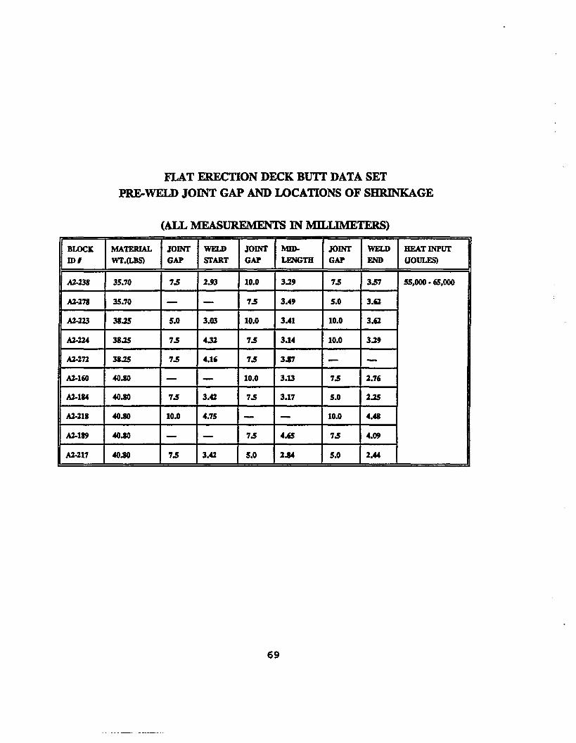
FLAT ERECTION DECK SEAM DATA SET
PRE-WELD JOINT GAP AND LOCATIONS OF SHRINKAGE
(ALL MEASUREMENT IN MILLIMETERS)
BLOCK MATERIAL JOINT WELD JOINT MID- JOINT WELD HEAT INPUT
I D # WT.(LBS) GAP START GAP LENGTH GAP END (JOULES)
A2-265 30.60/35.00 10.0 4.98 7.5 4.69 — — 55,000-6S,000
35.70 5.0 3.28 5.0 4.53 — —
A2-224 38.25 12.5 5.15 7.5 4.61 10.0 3.28
A2-223 38.25 10.0 3.78 7.5 4.90 — 4.15
A2-160 40.80 7.5 4.19 7.5 4.41 10.0 5.26
A2-159 40.80 — — 7.5 4.15 7.5 3.14
A2-1S9 40.80o 5.0O 3.58 7.5 3.98 5.0o 4.13
A2-218 40.80 10.0 3.83 10.0 5.87 7.5 5.89
A2-217 40.80 10.0 4.29 7.5 4.86 7.5 4.15
A2-141 45.90 — — 7.5 3.92 — —
A2-155 45.90 5.0 3.54 7.5 4.00 7.5 4.33
A2-156 45.90 10.0 4.64 10.0 4.75 — —
81

4.4 INDEPENDENT VARIABLES:
The welding heat input could be included in the analysis but because of the volume ofdata and the fixed ranges per data set, it was not included for the expediency of thisstudy.
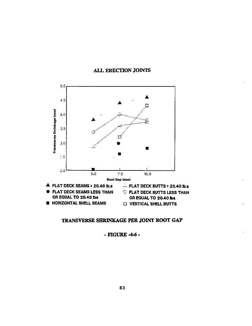
The next variable relates directly to the joint size. The pre-weld root gap fluctuates inthe range of 5.0mm to 10.0mm significantly affecting the joint size. Four (4) of the datasets reveal the relationship expected with increasing joint root gap and the increase intransverse weld shrinkage (Figure 4-6).
Erection deck joints (butts and seams) are commonly fit with the slip-tight stud fittingaids where as horizontal shell seams are fit-up with welded strongbacks which producegreater levels of restraint. The lower shrinkage levels of shell seams are evident in thegraph. Shrinkage variations of flat deck seam joints exit because of the combination ofrestraint types and inconsistency of application to suit erection requirements yet the meanshrinkage of deck butts at each joint gap size is less than 1mm despite the range of jointmaterial weights.
The condition of joint restraint influence the degree of weld joint shrinkage in a numberof ways. The size and weight of an erection block together with its positioning andsurrounding environment produce varying levels of restraint that will influence the degreeof weld shrinkage.
Localized restraint which is not applied consistently, that is the type and number of jointfitting aids, the number, size, and spacing of tack welds will influence shrinkage. Theseforms of joint restraint are localized will control shrinkage levels so that shrinkagefactors can be established. In the experimental testing phase of this project the spreadof shrinkage was analyzed with controlled restraint.
82

WELD SHRINKAGE STUDY ERECTION BLOCK BLOCK I I I I
JOINT DIAGRAMMATERIALTHICKNESSJOINT DESIGNBEVEL
DIMENSION ID LOCATION ROOT GAP PREWELD POSTlWELD SHRINKAGEMEASUREMENT MEASUREMENT
TIME/DATE
WELDINGAMPERAGE VOLTAGE SPEED INPUT
OBSERVATION
DATA SHEET FOR GATHERING DATA
84

5.0 EXPERIMENTAL TESTING
The intent of this experimental testing was to gather shrinkage data taken from jointswelded with two levels of heat input to illustrate the significance this independent variablecan have on the spread of shrinkage with two levels of joint restraint applied. Erectionjoints have other forms of restraint more complex, created by outside conditions thatcannot be altered. In these test conditions, restraint is controlled by a common tack sizeand two strongbacks. There is also a test joint welded at a high heat input with restraintcontrolled by a common tack size only.
Shrinkage results were obtained from test joints welded with the common attributes usedfor the erection deck joints. The joint design, the welding process, the method of weldingapplication and the joint position are all common. This comparative analysis ofshrinkage was evaluated for a range of common material weights.
Test assemblies were welded under restraint conditions with two strong backs positioned200mm from the joint ends. Test assemblies welded under no restraint conditions did nothave strongbacks. Instead two rollers were positioned above one side of the test joint inthe direction of transverse shrinkage (see Figure 5-2). Rotational distortion wascontrolled with two (2) freed wheels positioned on one side of the plate, however,transverse shrinkage for the most part was unaffcted because the wheels moved freelyin this direction.
Transverse shrinkage data is collected from three locations along each joint. Twopositions, weld start and weld end measurements are in the same location as thestrongbacks. The mid-length location is in the area of least restraint.
85

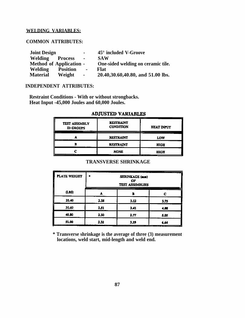
WELDING VARIABLES:
COMMON ATTRIBUTES:
Joint Design . 45° included V-GrooveWelding Process - SAWMethod of Application - One-sided welding on ceramic tile.Welding Position - FlatMaterial Weight - 20.40,30.60,40.80, and 51.00 lbs.
INDEPENDENT ATTRIBUTES:
Restraint Conditions - With or without strongbacks.Heat Input -45,000 Joules and 60,000 Joules.
TRANSVERSE SHRINKAGE
* Transverse shrinkage is the average of three (3) measurementlocations, weld start, mid-length and weld end.
87

TEST RESULTS:
This data provides useful information on the range of shrinkage variance under fixedconditions (controlled variables). Transverse shrinkage results for each test are shown inFigure 5-3. With reduced weld heat-input, base metal dilution is lower. Although lowerheat inputs will require a greater number of passes increasing the number of thermalcycles, greater shrinkage cannot be expected. Comparing joint group A and B which havethe same joint design and are welded with the same deposition rates, greater shrinkagelevels are resultant of higher heat input.
Comparison of transverse shrinkage between joints of the same design (45 degree included)produces a shrinkage spread over 3mm. The shrinkage spread between joints welded withstrongbacks at low deposition and high deposition heat inputs is less than lmm. When thejoint has no restraint (no strongbacks) the shrinkage levels increase dramatically.Establishing reasonable factors for shrinkage with this variance is not possible.
Erection block joints having potentially higher levels of shrinkage can have shrinkagecontrolled (reduced) with proper fitting and welding techniques. By control of theseunrestrained conditions, that is with proper fitting methods, overall joint shrinkage isreduced and shrinkage variance is controlled.
The usefulness of this data can only be used as pre-cursor to further testing. Knowing theshrinkage in a maximum restrain“ t condition, developed from these tests and the shrinkagedata collected for the third interim process, other fitting methods can be adapted.
88


6.0 CONCLUSION
If the welding attributes are not identical from shipyard to shipyard the weld shrinkagefactors developed in one yard, cannot be implemented in another yard, without analysis.Although the welding application may be common other uncommon attributes may affectshrinkage levels.
1st INTERIM PROCESS:
The degree of variability within the process is very high with respect to the meanshrinkage, so shrinkage factors must be designed to account for this variability.Predicted shrinkage factors are provided for both the one-sided and two-sidedapplications. These factors are regressed from the design attributes. The mean andstandard deviation are computed from the shrinkage data sets using the design attributes.
SHRINKAGE FACTORS- ONE-SIDED WELDING -
COMMON ATTRIBUTES:
Joint Design Squared ButtWeIding process SAwMethod of Application One Sided WeldingJoint Position
CHANGING ATTRIBUTES:
REGRESSION RESULTS
MATERIAL WEIGHT (LBS.) 10.20 15.30 20.40
SHRINKAGE FACTOR(mm) 0.9 1.0 1.2
CALCULATED
MEAN(x) STANDARD DEVIATION
0.97 0.25& A
90

SHRINKAGE FACTORS- TWO-SIDED WELDING
Joint Design Square Buttwelding Process SAWMethod of Application Two sided weldingJoint Position
CHANGING ATTRIBUTES:
Material Thickness (lbs0 12.75, 15.30, 20.40, 25.5welding Parameters (Adjusted by Material Weight)Joint GaPRestraint Condition l/2” Tacks spaced every 2’
REGRESSION RESULTS
MATERIAL WEIGHT (LBS.) 12.75 15.30 20.40 25.50
PREDICTED SHRINKAGE (mm) 0.9 0.9 0.7 0.6
CALCULATED
Transverse panel shrinkage in the second interim process lies within a range of 1.25 mm isdifficult to predict. The histograms of shrinkage data is an illustration of the lack ofsymmetry within this process. (Page 35)
Remembering that loss in design dimension from distortion is not accounted for. TheSecond Interim Process here, has the highest degree of variability. Variability is evenhigher when considering plate distortion another factor in overall loss of plate length. Withcontinuous high deposition welding processes distortion can be reduced but plate shrinkagewill always be part of the process.
3RD INTERIM PROCESS:
Predicted shrinkage factors for this specified joint design are provided for erection joints.The shrinkage factor for each welding application must be considered together with thestandard deviation for that process. If the deviation is too large the shrinkage factor isuseless.
Independent variables in the regression analysis are the material thickness and joint gap,for the weld start, mid-length, and weld end locations. The shrinkage factors are given foreach erection block joint position by the material thickness.
91

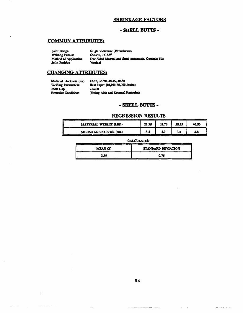
SHRINKAGE FACTORS
- DECK JOINTS -
COMMON ATIRIBUTES:
Joint Design Single V-Groove (45°included)Welding Process SAWMethod of Application one sided welding, Ceramic TileJoint Position Flat
CHANGING ATTRIBUTES:
Material Thickness Listed belowWelding Parameters Heat Input (55,000-6s,000Jti)Joint Gap 7.5mmRestraint Condition ( F i t t i n g & d s a a d E X t e r = d ~ )
ERECTION DECK BUTTS
REGRESSION RESULTS
MATERIAL WEIGHT (LBS) 12.75 15.30 20.40
SHRINKAGE FACT0R (mm) 4.4 4.1 3.5
CALCULATED
MEAN (x) STANDARD DEVIATION
4.04 0.88
92


GE FACTORS
-SHELL SEAMS -
Joint Design Single V-Groove (45°included)welding Process SMAW, FCAWMethod of Application one sided manual Semi- Automatic,“ Ceramic TileJoint Position Horizontal
CHANGING ATTRIBUTES:
M a t e r i a l~ Thickness (lbs ) 20.40,22.95, 28.05, 30.60welding Parameters Heat Input (30,000-40,000 Joules)Joint Gap 7.5mmRestraint Conditions (Fittigs Aids and External Restraint)
-SHELL SEAMS -
MATERIAL WEIGHT (LBS) 20.40 22.95 28.05 30.60
SHRINKAGE FACTOR (mm) 2.1 2.3 2.6 2.8
CALCULATED
This study was conducted to provide a "how to" approach for the establishment of weldshrinkage factors. It is readily apparent that the relationship of the three independentvariables on shrinkage can be analyzed much more thoroughly with a larger database andmore included variables. R2 is a measure of the percent variation the dependent variablehas with the independent variables. This value is considered low in each data set analyzed.A better understanding of the percent variation would be approached by including moreindependent variables that might be attributable to weld shrinkage in the regressionanalysis.
Other variables that could be included under a more extensive analysis include: The weldheat-input, the deposition rate, and number of tacks and strongbacks along each joint.Although it is true more variables included in the regression analysis could increase thepredictability of weld shrinkage, this may not be the case when considering the outsiderestraint conditions that cannot be controlled.
95

96
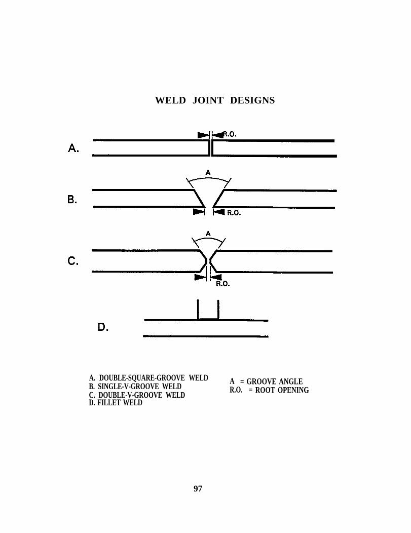
WELD JOINT DESIGNS
A. DOUBLE-SQUARE-GROOVE WELDB. SINGLE-V-GROOVE WELD
A = GROOVE ANGLE
C. DOUBLE-V-GROOVE WELDR.O. = ROOT OPENING
D. FILLET WELD
97