i.MX27 IP Camera Reference Design Reference …...Introduction i.MX27 IP Camera Reference Design...
32
i.MX27 IP Camera Reference Design Reference Manual MX27IPCRM Rev. 1.0 8/2008
Transcript of i.MX27 IP Camera Reference Design Reference …...Introduction i.MX27 IP Camera Reference Design...

i.MX27 IP CameraReference DesignReference Manual
MX27IPCRMRev. 1.0
8/2008

Freescale and the Freescale logo are trademarks or registered trademarks of Freescale Semiconductor, Inc. in the U.S. and other countries. Windows is a registered trademark of Microsoft Corporation. All other product or service names are the property of their respective owners. IEEE 802.11 and 802.3 are registered trademarks of the Institute of Electrical and Electronics Engineers, Inc. (IEEE). This product is not endorsed or approved by the IEEE.
© Freescale Semiconductor, Inc., 2008. All rights reserved.
Information in this document is provided solely to enable system and software
implementers to use Freescale Semiconductor products. There are no express or
implied copyright licenses granted hereunder to design or fabricate any integrated
circuits or integrated circuits based on the information in this document.
Freescale Semiconductor reserves the right to make changes without further notice to
any products herein. Freescale Semiconductor makes no warranty, representation or
guarantee regarding the suitability of its products for any particular purpose, nor does
Freescale Semiconductor assume any liability arising out of the application or use of
any product or circuit, and specifically disclaims any and all liability, including without
limitation consequential or incidental damages. “Typical” parameters which may be
provided in Freescale Semiconductor data sheets and/or specifications can and do
vary in different applications and actual performance may vary over time. All operating
parameters, including “Typicals” must be validated for each customer application by
customer’s technical experts. Freescale Semiconductor does not convey any license
under its patent rights nor the rights of others. Freescale Semiconductor products are
not designed, intended, or authorized for use as components in systems intended for
surgical implant into the body, or other applications intended to support or sustain life,
or for any other application in which the failure of the Freescale Semiconductor product
could create a situation where personal injury or death may occur. Should Buyer
purchase or use Freescale Semiconductor products for any such unintended or
unauthorized application, Buyer shall indemnify and hold Freescale Semiconductor
and its officers, employees, subsidiaries, affiliates, and distributors harmless against all
claims, costs, damages, and expenses, and reasonable attorney fees arising out of,
directly or indirectly, any claim of personal injury or death associated with such
unintended or unauthorized use, even if such claim alleges that Freescale
Semiconductor was negligent regarding the design or manufacture of the part.
Document Number: MX27IPCRMRev. 1.0, 8/2008
How to Reach Us:
Home Page: www.freescale.com
Web Support: http://www.freescale.com/support
USA/Europe or Locations Not Listed: Freescale Semiconductor, Inc.Technical Information Center, EL5162100 East Elliot Road Tempe, Arizona 85284 +1-800-521-6274 or+1-480-768-2130www.freescale.com/support
Europe, Middle East, and Africa:Freescale Halbleiter Deutschland GmbHTechnical Information CenterSchatzbogen 781829 Muenchen, Germany+44 1296 380 456 (English) +46 8 52200080 (English)+49 89 92103 559 (German)+33 1 69 35 48 48 (French) www.freescale.com/support
Japan: Freescale Semiconductor Japan Ltd. HeadquartersARCO Tower 15F1-8-1, Shimo-Meguro, Meguro-ku Tokyo 153-0064Japan 0120 191014 or+81 3 5437 [email protected]
Asia/Pacific: Freescale Semiconductor Hong Kong Ltd. Technical Information Center2 Dai King Street Tai Po Industrial Estate Tai Po, N.T., Hong Kong +800 2666 [email protected]
For Literature Requests Only:Freescale Semiconductor
Literature Distribution Center P.O. Box 5405Denver, Colorado 80217 +1-800 441-2447 or+1-303-675-2140Fax: +1-303-675-2150LDCForFreescaleSemiconductor
@hibbertgroup.com
ContentsParagraphNumber Title
PageNumber
i.MX27 IP Camera Reference Design Reference Manual, Rev. 1.0
Freescale Semiconductor 1
Chapter 1 Introduction
1.1 Acronyms and Terms. ....................................................................................................... .61.2 Additional Documentation................................................................................................ .71.3 Revision History................................................................................................................ .8
Chapter 2 H/W Architecture
2.1 i.MX27. ............................................................................................................................. .92.1.1 Core Clocks.................................................................................................................. .102.1.2 GPIO. ........................................................................................................................... .102.1.3 UARTs.......................................................................................................................... .122.1.4 Indicator LEDs............................................................................................................. .122.2 System Memory. ............................................................................................................. .122.2.1 DDR SDRAM.............................................................................................................. .132.2.2 Flash............................................................................................................................. .132.2.2.1 NOR. ...................................................................................................................... .132.2.2.2 NAND. ................................................................................................................... .132.3 Communications. ............................................................................................................ .132.3.1 Ethernet. ....................................................................................................................... .142.3.1.1 Clock. ..................................................................................................................... .142.3.1.2 Interface. ................................................................................................................ .142.3.2 SDIO. ........................................................................................................................... .142.3.3 USB.............................................................................................................................. .142.4 Audio. ............................................................................................................................. .152.5 WiFi Module. .................................................................................................................. .152.6 CMOS Sensor Interface. ................................................................................................. .152.7 I2C. ................................................................................................................................. .162.8 Power Supply. ................................................................................................................. .162.8.1 Power over Ethernet (POE). ........................................................................................ .162.8.2 5-V Boost. .................................................................................................................... .162.8.3 Power Management Unit. ............................................................................................ .162.8.4 Required Voltages. ....................................................................................................... .162.8.5 Power Start-up Sequence. ............................................................................................ .172.9 Processor Reset. .............................................................................................................. .172.10 JTAG................................................................................................................................ .172.11 Board Layout Requirements. .......................................................................................... .18
ContentsParagraphNumber Title
PageNumber
i.MX27 IP Camera Reference Design Reference Manual, Rev. 1.0
2 Freescale Semiconductor
Chapter 3 Camera Software
3.1 Camera Software Architecture........................................................................................ .193.2 Camera Software System Overview. .............................................................................. .193.3 Camera Software Components. ...................................................................................... .203.3.1 User Space Applications. ............................................................................................. .203.3.1.1 Telnet Server. ......................................................................................................... .203.3.1.2 Video Server........................................................................................................... .203.3.1.3 Command Line Interface (CLI). ............................................................................ .213.3.1.4 Common Gateway Interface (CGI)........................................................................ .213.3.1.5 Network Discovery. ............................................................................................... .213.3.1.6 Wireless LAN (WLAN)......................................................................................... .213.3.1.7 FTP Client/Server. ................................................................................................. .21L3.3.1.8 Linux Serial ........................................................................................................... .213.3.1.9 HTTP. ..................................................................................................................... .213.3.2 User Interfaces. ............................................................................................................ .213.3.2.1 Video Server........................................................................................................... .213.3.2.2 Sensor..................................................................................................................... .233.3.2.3 Webpages. .............................................................................................................. .243.3.2.4 Hardware Tests....................................................................................................... .243.3.3 Middleware Libraries................................................................................................... .253.3.3.1 Image Control. ....................................................................................................... .253.3.3.2 System Config........................................................................................................ .253.3.3.3 V4L2. ..................................................................................................................... .263.3.3.4 IO. .......................................................................................................................... .263.3.3.5 TCP/IP. ................................................................................................................... .263.3.3.6 USB........................................................................................................................ .263.3.3.7 I2C. ........................................................................................................................ .263.3.4 Kernel Space. ............................................................................................................... .263.3.4.1 Linux Kernel 2.6.19. .............................................................................................. .263.3.4.2 Network. ................................................................................................................ .263.3.4.3 USB........................................................................................................................ .263.3.4.4 RTC. ....................................................................................................................... .263.3.4.5 Serial. ..................................................................................................................... .263.3.4.6 Memory Technology Driver (MTD)...................................................................... .263.3.4.7 I2C. ........................................................................................................................ .273.3.4.8 CMOS Sensor Interface (CSI). .............................................................................. .273.3.4.9 Video Processing Unit (VPU)................................................................................ .273.3.4.10 SD/MMC. .............................................................................................................. .273.3.4.11 GPIO. ..................................................................................................................... .27

ContentsParagraphNumber Title
PageNumber
i.MX27 IP Camera Reference Design Reference Manual, Rev. 1.0
Freescale Semiconductor 3
3.3.4.12 WiFi. ...................................................................................................................... .273.3.4.13 Image Sensor (External to SoC). ........................................................................... .273.3.5 Linux Platform Support for i.MX27 . .......................................................................... .273.3.6 Redboot. ....................................................................................................................... .27
Appendix A Troubleshooting and Support
A.1.1 What video compression methods are supported?.......................................................... .28A.1.2 What are the supported transport protocols?. ................................................................. .28A.1.3 What kind of host software is used to decode the various data feeds?. .......................... .28A.1.4 Does the camera support still image capture?. ............................................................... .28A.1.5 What browsers are supported?. ....................................................................................... .28A.1.6 Are there any plans for supporting media servers such as RTSP in the future?. ............ .28A.1.7 Are there any plans for adding support for FLV based steams?. .................................... .28A.1.8 Do you plan to support MPEG-TS in the future?. .......................................................... .28A.1.9 Is there support and audio codec on the board?.............................................................. .29A.1.10 Is there a forum or discussion group that I can query prior to phoning technical support?...
.29A.1.11 What size image sensor is included in the reference design?. ........................................ .29

i.MX27 IP Camera Reference Design Reference Manual, Rev. 1.0
4 Freescale Semiconductor
Figures
2-1 Camera Block Diagram. ................................................................................................... .93-1 Camera Software Layout. ............................................................................................... .19
FigureNumber Title
PageNumber

i.MX27 IP Camera Reference Design Reference Manual, Rev. 1.0
Freescale Semiconductor 5
Tables
1-1 Acronyms and Terms. ....................................................................................................... .61-2 Revision History................................................................................................................ .82-1 GPIO Table. .................................................................................................................... .102-2 UART Transceiver Configuration Pins........................................................................... .123-1 Video Server Commands. ............................................................................................... .223-2 Sensor CGI Commands. ................................................................................................. .233-3 Hardware Test Files. ....................................................................................................... .243-4 Hardware Test Commands.............................................................................................. .25
TableNumber Title
PageNumber

Introduction
i.MX27 IP Camera Reference Design Reference Manual, Rev. 1.0
6 Freescale Semiconductor
Chapter 1 Introduction This document describes the technical details of the i.MX27 IP camera reference design. It details the hardware architecture and software system architecture, and provides information on the software integration. An FAQ is also provided to assist with getting the system up and running.
1.1 Acronyms and TermsTable 1-1 shows the acronyms and terms for this document.
Table 1-1. Acronyms and Terms
Term Definition
A/V Audio/Video
ALSA Advanced Linux® Sound Architecture
AP Access Point
AUDMUX Audio Multiplexer
BSP Board Support Package
CGI Common Gateway Interface
CLI Command Line Interface
CSI CMOS Sensor Interface
FS Full Speed-usage. USB-FS indicates max 12 Mbits per second data rates.
FEC Fast Ethernet Controller
FTP File Transfer Protocol
GPIO General Purpose Input/Output
GUI Graphical User Interface
HS High Speed-usage. USB-HS indicates max 480 Mbits per second data rates.
POE Power Over Ethernet
HTML Hyper Text Markup Language
HW Hardware or Hardware Design
I2C Inter Integrated Circuit
LED Light Emitting Diode
I2S Inter-IC Sound
IP Internet Protocol
IPVS IP Video System
LAN Local Area Network
MMC Multi Media Card

Introduction
i.MX27 IP Camera Reference Design Reference Manual, Rev. 1.0
Freescale Semiconductor 7
1.2 Additional DocumentationThe following documents contain additional information related to this reference manual:
• i.MX27 IP Camera Quick Start Guide (MX27IPCQSG)⎯Quick start guide to getting the camera demo running and streaming video using Windows Internet Explorer™ and FFPLAY
MPEG Motion Pictures Experts Group
MTD Memory Technology Driver
OSD On Screen Display
OTG On The GO–usage USB-OTG
PHY Physical Interface
PCB Printed Circuit Board
PCM Pulse Code Modulation
POST Power On Self Test
PSK Pre Shared Key
RAM Random Access Memory
RTC Real Time Clock
RTCP Real Time Control Protocol
RTP Real Time Protocol
RTSP Real Time Streaming Protocol
SDIO Secure Digital Input Output
SMTP Simple Mail Transfer Protocol
SOAD Sum Of Absolute Differences
SoC System on Chip
SPI Serial Peripheral Interface
SSI Synchronous Serial Interface
UI User Interface
USB Universal Serial Bus
UART Universal Asynchronous Receive Transmit
V4L2 Video For Linux version 2
VPU Video Processing Unit
WiFi Used to indicate IEEE Std 802.11™ WLAN protocol
WLAN Wireless LAN
WPA WPA Protected Access
Table 1-1. Acronyms and Terms (continued)
Term Definition

Introduction
i.MX27 IP Camera Reference Design Reference Manual, Rev. 1.0
8 Freescale Semiconductor
• i.MX27 IP Camera Software Guide—Provides instructions for installing the BSP and compiling the code for the Freescale i.MX27 IP camera.
1.3 Revision HistoryTable 1-2. Revision History
Revision Number
Date Substantive Change(s)
0 4/2008 Initial release
1 8/2008 Updated Figure 2-1, “Camera Block Diagram,” the WLAN functionality information in Section 3.3.1.6, “Wireless LAN (WLAN)” and Section 3.3.4.12, “WiFi,” module information in Section 2.5, “WiFi Module,” and the video compression method question in the FAQ.
H/W Architecture
i.MX27 IP Camera Reference Design Reference Manual, Rev. 1.0
Freescale Semiconductor 9
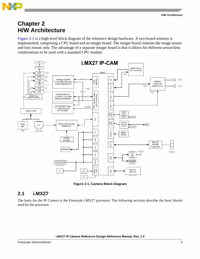
Chapter 2 H/W ArchitectureFigure 2-1 is a high-level block diagram of the reference design hardware. A two-board solution is implemented, comprising a CPU board and an imager board. The imager board contains the image sensor and lens mount only. The advantage of a separate imager board is that it allows for different sensor/lens combinations to be used with a standard CPU module.
Figure 2-1. Camera Block Diagram
2.1 i.MX27The basis for the IP Camera is the Freescale i.MX27 processor. The following sections describe the basic blocksused by the processor.
H/W Architecture
i.MX27 IP Camera Reference Design Reference Manual, Rev. 1.0
10 Freescale Semiconductor
2.1.1 Core Clocks
The i.MX27 requires two clock inputs.
• 32.768 kHz⎯on-chip oscillator driving a crystal provides clocking for sleep modes and the RTC.
— The 32.768 kHz crystal can be used to clock all functions in the processor; however, because this clock requires a large multiplication factor, the clock is not as stable.
— The 32.768 kHz is required to exit reset states properly and for the JTAG debug controller to work.
• 25 MHz⎯oscillator required as the primary clock. The i.MX27 can accept a crystal of 26 MHz or an external oscillator input between 16 and 32 MHz. Because there is already a 25 MHz oscillator for the Ethernet PHY, it will also be used for the processor input clock.
The core can be clocked at two speeds, 400 MHz and 266 MHz. For reduced power consumption, the processorshould be operated at the lowest core speed that allows the desired functionality.
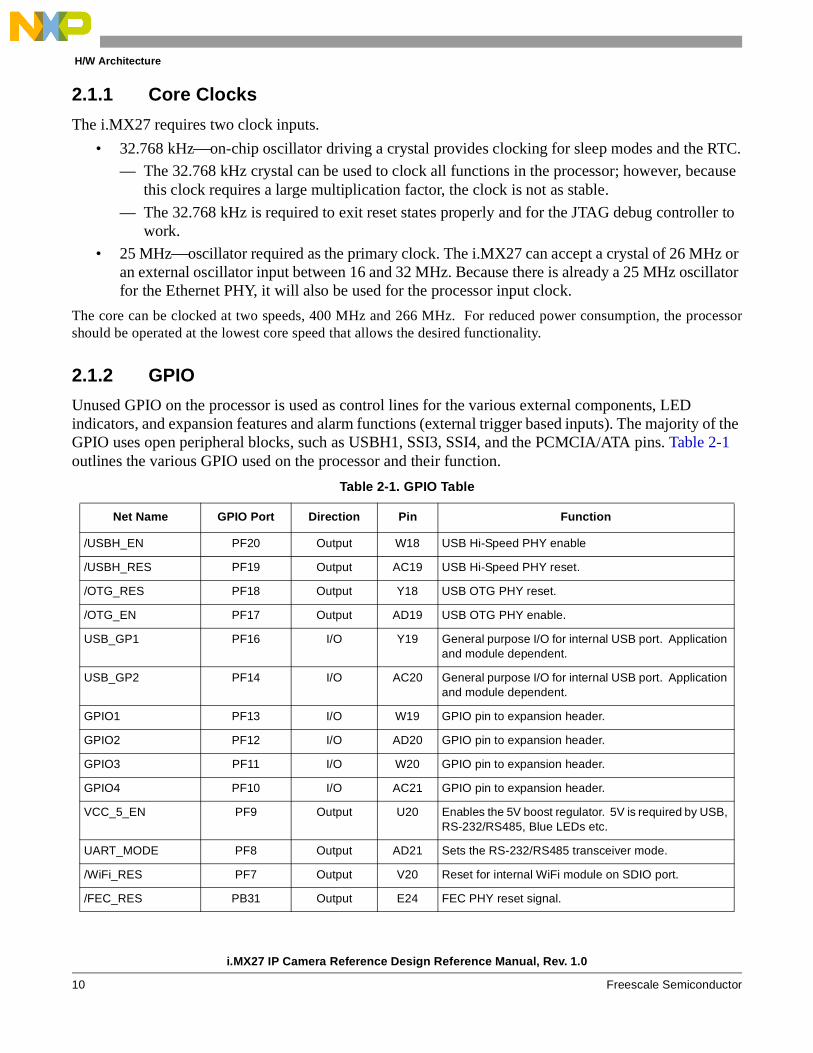
2.1.2 GPIO
Unused GPIO on the processor is used as control lines for the various external components, LED indicators, and expansion features and alarm functions (external trigger based inputs). The majority of the GPIO uses open peripheral blocks, such as USBH1, SSI3, SSI4, and the PCMCIA/ATA pins. Table 2-1 outlines the various GPIO used on the processor and their function.
Table 2-1. GPIO Table
Net Name GPIO Port Direction Pin Function
/USBH_EN PF20 Output W18 USB Hi-Speed PHY enable
/USBH_RES PF19 Output AC19 USB Hi-Speed PHY reset.
/OTG_RES PF18 Output Y18 USB OTG PHY reset.
/OTG_EN PF17 Output AD19 USB OTG PHY enable.
USB_GP1 PF16 I/O Y19 General purpose I/O for internal USB port. Application and module dependent.
USB_GP2 PF14 I/O AC20 General purpose I/O for internal USB port. Application and module dependent.
GPIO1 PF13 I/O W19 GPIO pin to expansion header.
GPIO2 PF12 I/O AD20 GPIO pin to expansion header.
GPIO3 PF11 I/O W20 GPIO pin to expansion header.
GPIO4 PF10 I/O AC21 GPIO pin to expansion header.
VCC_5_EN PF9 Output U20 Enables the 5V boost regulator. 5V is required by USB, RS-232/RS485, Blue LEDs etc.
UART_MODE PF8 Output AD21 Sets the RS-232/RS485 transceiver mode.
/WiFi_RES PF7 Output V20 Reset for internal WiFi module on SDIO port.
/FEC_RES PB31 Output E24 FEC PHY reset signal.

H/W Architecture
i.MX27 IP Camera Reference Design Reference Manual, Rev. 1.0
Freescale Semiconductor 11
FEC_INT PB30 Input J20 FEC PHY Interrupt.
/SD1_WP PB29 Input D24 SDIO Port 1 Write Protect.
/SD1_DET PB28 Input F19 SDIO Port 1 Detect.
/SD2_WP PB27 Input C24 SDIO Port 2 Write Protect.
/SD2_DET PB26 Input E19 SDIO Port 2 Detect
BLUE2 PB25 Output H22 Blue LED 2
BLUE1 PB22 Output G19 Blue LED 1
UART_DXEN PE14 Output A18 Used for RS-485 half duplex direction
UART_RXEN PE15 Output C16 Used for RS-485 half duplex direction.
UART1_RXD PE13 Input F16 Receive input for RS-232/RS485 communications.
UART1_TXD PE12 Output B17 Transmit Output for RS-232/RS485 communications.
UART3_RTS PE11 Input E15 Expansion Header UART3 RTS or GPIO
UART3_CTS PE10 Output A17 Expansion Header UART3 CTS or GPIO
UART3_RXD PE9 Input F15 Expansion Header UART3 RXD or GPIO
UART3_TXD PE8 Output B16 Expansion Header UART3 TXD or GPIO
GPIO5 PE4 I/O A14 GPIO pin to expansion header.
GPIO6 PE3 I/O E12 GPIO pin to expansion header.
GPIO7 PE7 I/O E14 GPIO pin to expansion header.
GPIO8 PE6 I/O A16 GPIO pin to expansion header.
CSI_STBY PC19 Output B8 CMOS Imager standby (puts image sensor into low power state).
/CSI_RES PC18 Output G8 CMOS Imager reset
CSI_GP1 PC17 Output A8 Imager GP output (control LED on Imager board)
CSI_GP2 PC16 Output F8 Imager GP output (control LED on Imager board)
RED1 PC28 Output E10 Debug LED 1
RED2 PC29 Output A11 Debug LED 2
RED3 PC30 Output C9 Debug LED 3
RED4 PC31 Output B11 Debug LED 4
Table 2-1. GPIO Table (continued)
Net Name GPIO Port Direction Pin Function
H/W Architecture
i.MX27 IP Camera Reference Design Reference Manual, Rev. 1.0
12 Freescale Semiconductor
NOTEThe default state is outputs for some of the pins used as GPIO and is defined as either high or low out of reset. These must be set up properly in the Bootloader. Choosing pins to use as GPIO that default as inputs out of reset allows pull-up/pull-down resistors to be used to set the desired state out of reset. The i.MX27 also has internal pull-up and pull-down resistors that set the default state of the pins out of reset. Refer to MCIMX27 Multimedia Applications Processor Reference Manual (MCIMX27) for information on the default configuration of the pins that are used as GPIO.
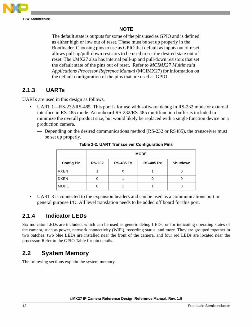
2.1.3 UARTs
UARTs are used in this design as follows.
• UART 1⎯RS-232/RS-485. This port is for use with software debug in RS-232 mode or external interface in RS-485 mode. An onboard RS-232/RS-485 multifunction buffer is included to minimize the overall product size, but would likely be replaced with a single function device on a production camera.
— Depending on the desired communications method (RS-232 or RS485), the transceiver must be set up properly.
• UART 3 is connected to the expansion headers and can be used as a communications port or general purpose I/O. All level translation needs to be added off board for this port.
2.1.4 Indicator LEDsSix indicator LEDs are included, which can be used as generic debug LEDs, or for indicating operating states ofthe camera, such as power, network connectivity (WiFi), recording status, and more. They are grouped together intwo batches: two blue LEDs are installed near the front of the camera, and four red LEDs are located near theprocessor. Refer to the GPIO Table for pin details.
2.2 System MemoryThe following sections explain the system memory.
Table 2-2. UART Transceiver Configuration Pins
MODE
Config Pin RS-232 RS-485 Tx RS-485 Rx Shutdown
RXEN 1 0 1 0
DXEN 0 1 0 0
MODE 0 1 1 0

H/W Architecture
i.MX27 IP Camera Reference Design Reference Manual, Rev. 1.0
Freescale Semiconductor 13
2.2.1 DDR SDRAMDDR SDRAM provides the maximum possible data throughput for the system. During the boot sequence, theoperating system and programs are copied from the non-volatile flash memory into RAM for execution. Theminimum amount of RAM must equal the amount of flash used for program and kernel storage. To satisfy therecommendations for Linux and program store, 64 Mbytes of DDR SDRAM is available. To save part space, asingle 32-bit-wide, 512-Mbit part is implemented, with the option to populate 1-Gbit parts if required (for 128Mbytes of memory). The Micron® MT46H16M32LFCM part is chosen for this application; it has various speedgrades and is available in an industrial temperature part.
Because all the memory components share the address bus, all parts use 1.8-V supplies.
The DDR memory uses the i.MX27 DDR memory controller, which provides dedicated data lines for the memory.The address lines are shared with other devices on the memory bus (such as NOR flash). All devices must be either1.8 V or appropriate voltage translation buffers must be added. Care must be taken during design to ensure the busloading and timing of the memory is within the manufacturer’s specifications. For this reference design, there isonly one part on the DDR bus, and no additional buffers or series resistors are added. The drive strengths for theprocessor and the memory can be adjusted in software to ensure proper signal integrity. For this design, theprocessor is set to normal, and the DDR is set to half drive.
2.2.2 FlashTwo types of Flash are included on the IPCAM reference design: NAND flash offers greater density at a reducedcost over NOR flash (with shorter programming times), but can be more difficult to use due to required errorcorrection and NAND flash controller requirement. To provide the greatest flexibility for firmware development, asmall 32-Mbyte NOR part and a 128-Mbyte NAND part are included.
2.2.2.1 NOR
The NOR flash uses the Spansion® S29WS256 series part. This part provides 256 Mbits of storage with a 16-bitbus. It shares the address lines with the DDR, and the 1.8-V part is used. The i.MX27 takes care of address offsets,and the address bus of this 16-bit part starts at A0. This particular part is also available with PSRAM (S71WSseries), and unused pins on the device are connected so this part can be upgraded.
2.2.2.2 NAND
NAND flash offers a higher density storage medium than NOR, with some extra error correction requirements.NAND offers improved programming times. The i.MX27 supports boot from NAND, which is the preferred bootmethod, allowing the NOR flash to be removed from the end product, which reduces product cost.
The Samsung® K9F1G08R0A provides 1 Gbit of storage in an 8-bit interface. Because the NAND shares the databus with NOR, it must be a 1.8-V device as well. Control of the NAND is accomplished by using the i.MX27’sinternal NAND flash controller. An alternative ST NAND01GR series part is also available for the camera and canbe used as a second source. Unlike the NOR flash, the NAND flash package is commonly used by differentmanufacturers, allowing flexibility of manufacturers and densities to be used.
2.3 CommunicationsSeveral means of communications are required, including wired Ethernet, wireless Ethernet using IEEE 802.11G,and USB.

H/W Architecture
i.MX27 IP Camera Reference Design Reference Manual, Rev. 1.0
14 Freescale Semiconductor
2.3.1 EthernetThe i.MX27 uses a fast Ethernet controller (FEC) onboard. The FEC does not include an internal PHY, andrequires an external MII-compatible transceiver and appropriate magnetics to be added.
The Micrel® KSZ8041NL includes the Auto MDI function, which auto detects if a crossover cable is required andconfigures the PHY accordingly. This is connected to the Halo® HFJ11-RP48E-L12RL RJ45 with integratedmagnetics and diode bridges to provide isolation with POE power supply. Using the integrated connector greatlyreduces the board space required to implement the POE and Ethernet interface.
2.3.1.1 Clock
The KSZ8041NL requires a 25-MHz clock, and an oscillator is used to provide this. This oscillator output is leveltranslated to 2.75 V and provides the high frequency clock to the processor and the Audio Codec, reducing overallsystem cost.
2.3.1.2 Interface
The FEC is shared with the ATA bus, which is not required for this design. Because the PHY is a 3.3-V part, allsignals from the PHY to the processor must be level translated to 2.75 V to protect the processor. However, signalsfrom the processor meet the minimum input voltage of the PHY. The Fairchild® FXL4245 level translators providethe down conversion.
If an ATA device is required (such as an IDE hard disk drive), then an external Ethernet MAC/PHY is required, oralternatively, an USB to IDE bridge could be implemented.
2.3.2 SDIOTwo SDIO connections are available: one externally for use with standard SDIO cards that could be used formemory expansion or other functions (such as WiFi), and an internal header for use with an expansion module. Theinternal connector allows for an internal WiFi module with SDIO interface to be connected. To support all SDIOcards, a 3.3-V interface is provided, with appropriate level translation on the four data lines to protect the processor.
2.3.3 USBThe i.MX27 requires an external transceiver (PHY) for USB Hi-Speed support. Host Port 2 connected to a ULPItransceiver gives full Hi-Speed support when using the ISP1504A USB PHY. This port is used to connect to aninternal 2 mm header, which can be used by an IEEE 802.11G USB WiFi module internally. In addition, thei.MX27 OTG port is implemented with the ISP1504A and connected to a Mini AB USB connector to provide anexternal USB connection. These parts require a 19.2-MHz crystal or oscillator as the clock source and haveprovisions internally for 2.75-V to 3.3-V conversions.
A USB power switch handles the VBUS switching on both ports. A total current of 500 mA is available for bothports combined, which limits the requirements on the boost switching supply. It is recommended the OTG port belimited to low power devices to allow enough power for an internal WiFi module. For applications requiring higherUSB power, the boost regulator needs to be upgraded.
H/W Architecture
i.MX27 IP Camera Reference Design Reference Manual, Rev. 1.0
Freescale Semiconductor 15
2.4 AudioTo provide the ability for two-way audio, a Wolfson® WM8974 CODEC is added. This codec includes goodsupport for various microphone configurations, and includes a 900-mW speaker driver to directly drive a smallspeaker. A small 16 mm x 35 mm, 1-W speaker provides the audio output. The codec’s ADC implements anautomatic level control (ALC) and up to 55.25 dB of gain, offering a wide range of microphone audio performance.The codec connects to the CPU using SSI port 1 for audio data, and CSPI port 1 for configuration communications.This device also provides a 2.75-V digital interface for direct connection to the processor.
The WM8974 also includes an internal PLL, and a wide range of input frequencies is allowed. This device canshare the 25-MHz clock with the processor and Ethernet PHY, reducing parts count.
Power for the speaker drive is also shared with the USB ports, and thus maximum speaker drive and USB powermay not be available.
NOTEAlthough the hardware for this module is included in the reference design, it is included for future development only. It has not been tested or had software implemented at this time.
2.5 WiFi ModuleTo provision the camera for wireless operations, an IEEE 802.11 b/g module is supported on the internal SDIO portusing a daughter card. Any available module with an appropriate interface, power profile, and firmware supportcould be integrated in the future.
The APM6828 SDIO system module based on CSR® WiFi is implemented in reference design for futureintegration.
The CSR module requires 1.5 V to operate the analog sections of the device. This supply is generated from thepower management unit LDO. A set of jumpers is included to allow the processor AVDD to also be supplied withthis LDO in the case the CSR module is not included (the output voltage would need to be adjusted appropriatelyfor this application).
NOTEAlthough the hardware for this module is included in the reference design, it is included for future development only. It has not been tested or had software implemented at this time.
2.6 CMOS Sensor InterfaceThe Micron MT9D131 2MP sensor is used for the sensor. This sensor connects directly to the i.MX27 CMOSsensor interface (CSI). The CMOS sensor is located on the imager daughter board via a 2-mm header. In additionto the CSI interface requirements, I2C connections are required for module control.
The Micron sensor includes the image processor onboard, and all electronic pan/tilt/zoom functions areaccomplished by the sensor before the data is transmitted to the processor. Clocking for the imager is provideddirectly by the i.MX27, allowing a wide range of resolutions and frame rates to be used.
The image sensor requires two power supply voltages, as follows:
• 2.75 V⎯Required for analog supply and digital interface voltages

H/W Architecture
i.MX27 IP Camera Reference Design Reference Manual, Rev. 1.0
16 Freescale Semiconductor
• 1.8 V⎯Required for the sensor digital core
2.7 I2CThe i.MX27 provides two I2C ports. One port is used for configuration of the camera sensor; the second is a general purpose bus with the following devices:
• Camera core EEPROM⎯used for camera core specific configuration parameters such as MAC address, board revision, serial number, and others
• Future Expansion
Because the processor uses a 2.75-V interface, these I2C buses must be pulled up to 2.75 V or use a voltagetranslation buffer in between.
2.8 Power SupplyIn addition to POE support, the device accepts a 12-V DC supply input. This allows standard security camera 12-Vpower to be used, as well as an AC adapter. The i.MX27 has several power supply voltage requirements. Atwo-stage power system is used for this design.
2.8.1 Power over Ethernet (POE)The first stage of the power system involves the Power over Ethernet (POE) solution. The National® LM5071provides an isolated POE system as well as support for an external 12-V DC input. It also includes and internalDC/DC converter, and using a flyback topology, provides 3.3-V output. This is the primary output voltage for theboard, and all other voltages are derived from this. The primary advantage of this part over standard POE devices isthe ability to change the under voltage protection, as well as allow the DC/DC converter to work down to 10.5 V(measured at the DC/DC converter). This allows an external 12-V supply to be easily connected to provide powerto the system when POE is not available. 12 V is also a standard security camera voltage.
2.8.2 5-V BoostBecause the POE controller outputs 3.3 V, a 5-V boost is added to supply the USB ports, blue LEDs, andRS-232/485 transceiver. If these features are not required, or if connecting to externally powered USB devices, the5-V boost can be removed. The MIC2295 is a high power 1.2-MHz boost with integrated FETS, and can provide 5V at 500 mA from the 3.3-V supply. The 1.2 MHz switching frequency allows for smaller magnetics to be used toreduce board space, yet still maintains good efficiency.
2.8.3 Power Management UnitTo provide the remaining voltages for the system, a National LM26480 power management unit is used to stepdown the 3.3-V supply. This part includes two switching regulators and two LDOs, which can be used to derive theremaining supply voltages.
2.8.4 Required VoltagesThe required voltages are as follows:
• 3.3 V⎯Primary logic voltage of the processor card
H/W Architecture
i.MX27 IP Camera Reference Design Reference Manual, Rev. 1.0
Freescale Semiconductor 17
— Switching regulator output from the POE module
— Used by the Ethernet PHY, analog Audio, USB transceiver
• CPU Core
— Provided by the power management unit Buck 1 switching regulator
— 1.2- to 1.52-V supply depending on processor operating speed. To simplify the system, this supply is fixed at 1.4 V, which allows operation at any processor clock.
• 2.75 V
— To satisfy the maximum long term operating voltages of the i.MX27 and the peripheral devices, an I/O voltage of 2.75 V is required.
— This also supplies the camera sensor.
— This is derived from LDO1 on the power management unit.
• Memory
— All the memory devices operate at 1.8 V. This is derived from Buck 2 from the power management unit.
• Analog supply
— The i.MX27 requires a 1.4-V supply for the PLL and other support circuits. This is derived from the power management unit LDO2. Alternatively, this supply can be set to 1.5 V to power the APM WiFi module. The analog supplies can be powered from the CPU core voltage.
2.8.5 Power Start-up SequenceThe i.MX27 requires a certain start-up sequence for the voltages to ensure the internal fuse remains intact. Thebasic requirement is that FUSE_VDD goes high after VCC_CORE. This is accomplished by delaying the VCC_18(1.8V) rail, which powers FUSE_VDD during normal operation.
2.9 Processor ResetThe power management unit includes an internal power on reset signal that monitors the two buck regulators. Thisis fed to an additional reset monitor that monitors the 3.3-V supply as well as provides a manual reset signal, whichis controlled via a switch with external access.
2.10 JTAGTo save board space, a 2-mm, 10-pin header is used for the JTAG connector. This requires an external adaptorboard to provide the interface to a 3rd party debugger/programmer.
The i.MX27 JTAG port only works with the boot mode set to USB/UART (All boot pins LOW). If JTAG is to beused in the end system, it is advised that the user include jumpers to be able to set the BOOT pins appropriately forJTAG control. This is especially required if JTAG is to be used for initial programming of the devices.
Once initial programming is complete, the BOOT mode can be switched for normal operation.

H/W Architecture
i.MX27 IP Camera Reference Design Reference Manual, Rev. 1.0
18 Freescale Semiconductor
2.11 Board Layout RequirementsTo simplify the layout and manufacturing of the PCB, traditional board layout techniques were employed. Theboard design is based on excluding the need for blind/buried/micro vias, which reduces the cost and improves theyield of the PCB design. For this reference design, a ten-layer design was implemented (six signal layers, threeground planes, and one power plane).
To route out the i.MX27 BGA, 4-mil traces with 4-mil spacing is required, along with 14-mil vias with a 6-milhole. Be sure to check with the board manufacturer for their capabilities, as some prefer to reduce the annular ringon the vias in favor of a larger hole. Alternatively, to reduce overall product size, blind, buried, or micro vias couldbe used.
Camera Software
i.MX27 IP Camera Reference Design Reference Manual, Rev. 1.0
Freescale Semiconductor 19
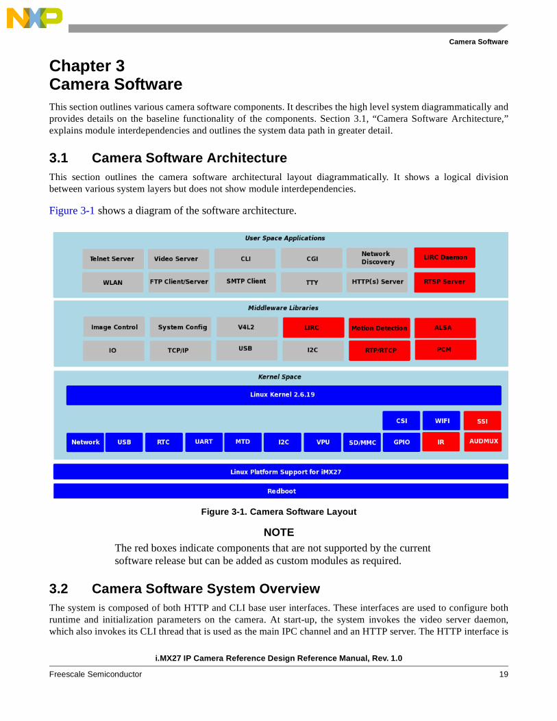
Chapter 3 Camera SoftwareThis section outlines various camera software components. It describes the high level system diagrammatically andprovides details on the baseline functionality of the components. Section 3.1, “Camera Software Architecture,”explains module interdependencies and outlines the system data path in greater detail.
3.1 Camera Software ArchitectureThis section outlines the camera software architectural layout diagrammatically. It shows a logical divisionbetween various system layers but does not show module interdependencies.
Figure 3-1 shows a diagram of the software architecture.
Figure 3-1. Camera Software Layout
NOTEThe red boxes indicate components that are not supported by the current software release but can be added as custom modules as required.
3.2 Camera Software System OverviewThe system is composed of both HTTP and CLI base user interfaces. These interfaces are used to configure bothruntime and initialization parameters on the camera. At start-up, the system invokes the video server daemon,which also invokes its CLI thread that is used as the main IPC channel and an HTTP server. The HTTP interface is

Camera Software
i.MX27 IP Camera Reference Design Reference Manual, Rev. 1.0
20 Freescale Semiconductor
used to communicate with remote clients and uses a CGI to convert requests into the appropriate system calls. Thesystem uses a sensor- specific user space application to configure the sensor driver and a CLI interface to configurethe video server.
When starting a session, the user should expect the following as a typical sequence of events:
1. A user connects to the target using HTTP, which serves up the main camera page to the client.
2. The client configures the camera based on a set of desired options.
3. Once the camera is configured, a TCP based session is requested from the HTTP server via the CLI to the video server.
4. The video server configures the VPU (Video Processing Unit) accordingly and requests a video streaming session from the kernel using the V4L2 interface. If successful, the video sever spawns an encoder thread and moves to an idle state.
5. Upon reception of a raw frame from the kernel, the encoder thread feeds the frame into the VPU engine for processing. Upon completion, the encoded frame is passed back to the video server for transmission. Along the chain from the sensor interface to the encoder thread, the raw image is also fed into the image processing unit (IPU) where color space conversion (CSC) operations take place. This step is required because the image format being captured via the CMOS sensor interface (CSI) is formatted in a YUV422 but the VPU requires that the format of the raw frames fed into the unit are in a YUV420 format.
The IPU can also be used to perform image resizing if required.
Once the session is running, the video server can be paused/resumed or terminated as in the case of sessioncompletion.
The host application, which is executed upon a successful connection to the video server, reads the frame off theTCP socket decodes them and updates the display window on the host in real time.
3.3 Camera Software Components
3.3.1 User Space ApplicationsThis section provides a brief description of the system software components. Note that all system components arenot described (for example, DMA driver because the usage is implied by higher level drivers).
3.3.1.1 Telnet Server
The Telnet server is used to allow a user to connect to the system using TCP/IP. The server presents a shellinterface to the logged in user. From the shell interface, system commands and programs can be executed, but arelimited to the constraints applied by the user’s file permissions.
3.3.1.2 Video Server
The video server is used to interpret and execute various video stream commands, such as frame rate, resolution,bit rate, encoding scheme, stream startup and shutdown, and motion detection. Once a stream is set up and started,the encoded frames are forwarded to the client’s destination port. The service is responsible for packaging the rawdata into an appropriate transport format, which may include MPEG2 Transport streams or raw data.

Camera Software
i.MX27 IP Camera Reference Design Reference Manual, Rev. 1.0
Freescale Semiconductor 21
3.3.1.3 Command Line Interface (CLI)
The command line interface (CLI) is used as the main control interface for the camera. Invocation of the CLI canbe done through various local and remote interfaces such as HTTP via CGI, Telnet, and Serial, to handlecommands. The CLI contains a set of predefined commands to enable it to redirect library or IPC calls to theappropriate endpoint. Upon call return, the CLI formats the response and returns it the calling process.
3.3.1.4 Common Gateway Interface (CGI)
Common gateway interface (CGI) is used to bridge HTML commands and responses between the HTTP(s) serverand the system. When a CGI command is received during the HTTP session, the appropriate CLI command isinvoked depending on the command type. The response is formatted into the proper HTML tag and displayed inthe camera web page.
3.3.1.5 Network Discovery
Network discovery comprised the dynamic host control protocol (DHCP), which is used to configure the cameras’IP address, network mask, DNS, and default gateway. The network discovery service is also used to configuresystem time using NTP if this option is enabled. The service is started early in the system boot process so that anyother services that depend on network connectivity can be started reliably.
3.3.1.6 Wireless LAN (WLAN)
WLAN functionality is not currently implemented in the reference design.
3.3.1.7 FTP Client/Server
FTP and/or TFTP is used to move files to and from the target.
3.3.1.8 Linux Serial
Linux serial is used for serial console connections, such as the system shell.
3.3.1.9 HTTP
The HTTP server is used to present web pages and process commands from a client browser. The server processesincoming commands and routes them to a local service that dispatches the command to the appropriate handler.The response data is converted into an HTML format and presented to the client browser.
3.3.2 User InterfacesThis section explains the user interfaces for the i.MX27 IP Camera.
3.3.2.1 Video Server
The video server, v2ipd, is automatically started by default and is controlled over UDP port 60000.
On the host machine with netcat (‘/usr/bin/nc’), type echo <command> | nc –u <camera_ip> 60000. If thecommand is a query command, the result is printed to the port and displayed by netcat.

Camera Software
i.MX27 IP Camera Reference Design Reference Manual, Rev. 1.0
22 Freescale Semiconductor
NOTE
Ensure the correct nc application is used; the application supplied with X does not work.
Table 3-1 displays the video server commands.
Table 3-1. Video Server Commands
Command Function
set_dest_addr Set the destination ip address for INET transport
set_dest_port Set the destination port number for INET transport
start_video Start video capture
pause_video Pause video capture
stop_video Stop video capture
start_audio Start audio capture
stop_audio Stop audio capture
reboot Reboot the system
set_transport_type Sets data transport type, (tcp, udp, or pipe)
set_gopsize Sets Group of Pictures size
set_bitrate Sets Sampling Bitrate
set_framerate Sets Video framerate
set_rotation_angle Sets Video rotation angle
set_output_ratio Sets Video output rotation angle
set_mirror_angle Sets Video Mirror angle
set_compression Sets Video compression type
set_resolution Sets Video resolution
get_transport_type Gets data transport type, (tcp, udp, or pipe)
get_gopsize Gets Group of Pictures size
get_bitrate Gets Sampling Bitrate
get_framerate Gets Video framerate
get_rotation_angle Gets Video rotation angle
get_output_ratio Gets Video output rotation angle
get_mirror_angle Gets Video Mirror angle
get_compression Gets Video compression type
get_resolution Gets Video resolution
update_video_conf Update new Video encoder configuration
reset_video_conf Restores Video encoder configuration defaults
restart_server Soft restart of server

Camera Software
i.MX27 IP Camera Reference Design Reference Manual, Rev. 1.0
Freescale Semiconductor 23
For set commands, the value is passed by concatenating =<value> to the command. For example, to set thetransport type, send set_transport_type=tcp.
NOTEThe reboot command, for good and bad, allows privilege escalation because a non-root user can send the command to the video server, which does a normally root-privileged command. This allows rebooting by the web server, which runs as an unprivileged user.
The video server can also be restarted by hand to obtain more debugging information. While run as a daemonprocess, errors are put in the log file v2ipd.log under /tmp.
Usage: v2ipd [-v <config>] [-a <config>] [-F] [-C]
-v video configuration file
-a audio configuration file
-C start up cli (control on UDP port 60000)
-F do not daemonize (foreground)
The video server maintains configuration across restarts in a file normally located at /etc/v2ipd/video.cfg. In thisfile, all the configurations available on the encoder webpage can be manually set.
3.3.2.2 Sensor
The sensor application, camif.cgi, can be found under /usr/cgi-bin. It must always be run from this directory because it stores state information in files located in the current working directory.
Typical commands include brightness, saturation, ae (autoexposure), awb (automatic white balance), gamma,flipmirror, colortemp, sharpness, fps, zoom, pan, and resolution. There is also a combination setting that allowsmultiple settings to be set or read at the same time.
get_firmware_info Gets firmware build information
get_firmware_rev Gets firmware revision number
get_video_state Gets state of video server
Table 3-2. Sensor CGI Commands
Command Function
camif.cgi –help=all Display of all supported commands
camif.cgi –help=<command> Display command usage
camif.cgi –read --<command>=0 Read the setting from the sensor or configuration file for the command
camif.cgi –write --<command>=<val> To write a new setting, ‘<val>’, to the sensor and configuration file for the given command
Table 3-1. Video Server Commands (continued)
Command Function

Camera Software
i.MX27 IP Camera Reference Design Reference Manual, Rev. 1.0
24 Freescale Semiconductor
3.3.2.3 Webpages
See i.MX27 IP Camera Quick Start Guide (MX27IPCQSG) for installing and configuring ffplay software onWindows®.
On all pages, there is a navigation header. This header allows the user to go to different pages of the webpage andcontrol the video stream. The CONTROLS page is used to pan, tilt, zoom, and capture a JPEG image. TheSENSOR page is used to change the image sensor settings. The ENCODER page is used to change the video serverand video for Linux (v4l) settings. The SYSTEM page allows the upgrading and changing of network settings.Finally, the top right contains controls for the video stream.
The play button plays the stream in a separate window when stopped, or restarts it when paused (user must nothave closed the window). The pause button pauses the video stream, but discards video until the play button ispressed. The stop button stops the stream, but does not close the video stream window.
The System webpage has three sections. The first section displays the serial port baud rate and the version of thevideo server software. The second section displays the wired and wireless network settings and allows the user tochange them to meet their needs. If both interfaces are disabled, the webpages will not be accessible after the nextreboot. The third section allows the user to upload an application patch. If a patch is uploaded or network settingsare changed, the user must press a reboot button for the changes to take affect.
The Encoder webpage has settings for codec version, bitrate, framerate, resolution, mirroring, image rotation, andgroup of pictures. There are some restrictions for valid combinations of settings. For example, H.263 codec islimited to one of the CIF-family of resolutions. For more information, there is a help button that opens a pagecontaining details about the different settings.
The Sensor webpage has settings for image brightness, contrast, white balance, gamma, saturation, sharpness,sensor frame rate, auto exposure, and sensor rotation. The changes affect the image sensor. Setting a fixed framerate is mutually exclusive with most of the other settings. To be able to manually adjust them, the frame rate mustbe set to auto. Also PTZ resets the frame rate to auto.
The Controls webpage allows the user to pan, tilt, zoom, and capture and image. The arrow buttons pan and tilt thecamera image. The plus and minus buttons zoom in and out, respectively. However, these buttons do not work atVGA resolution at this time. The re-center button immediately puts the camera back in the original position. The“Capture JPEG” button requests that the camera store a snapshot from the lens. This interrupts any active videostreams. A few seconds later, the user is able to press the “View Image” button to view the captured JPEG image.
3.3.2.4 Hardware Tests
On the target file system, move to the /tests directory. The following files are located there, as shown in Table 3-3.
Table 3-3. Hardware Test Files
Command Function
sdio Basic SDIO device test (requires SD card)
nand Basic NAND MTD device test
Nor Basic NOR MTD device test
ram Basic RAM device test
csi Basic CMOS sensor image capture test

Camera Software
i.MX27 IP Camera Reference Design Reference Manual, Rev. 1.0
Freescale Semiconductor 25
Test results are saved in the /test/results/results.txt.
From the /test directory execute the following commands, as shown in Table 3-4.
After executing the above commands test results is placed in ./results/results.txt. To view the results type:
cat ./results/results.txt
3.3.3 Middleware LibrariesThis section explains the libraries for the i.MX27 IP Camera.
3.3.3.1 Image Control
The image control library provides a user space API that allows an application to control imaging hardware as wellas contain any algorithms that may be used the application.
The camera control service interprets and executes various camera commands such as electronic pan tilt and zoom(EPTZ), adding time stamping overlays to raw frames at a prescribed interval (for example, updated at 1 secondresolution), and image scaling.
3.3.3.2 System Config
The system control service interprets and executes system level commands, such as WPA configuration, eventtriggers, administrator and user passwords, system service status, system health, and gathering system statistics.
net Basic wired and USB WIFI network test
otg Basic USB OTG port test (requires USB memory stick)
validate Main execution script
Table 3-4. Hardware Test Commands
Command Function
./validate sdio Execute SDIO unit test
./validate nand Execute NAND unit test
./validate nor Execute NOR unit test
./validate ram Execute RAM unit test
./validate csi Execute Image Sensor unit test
./validate net <ifname> <ipaddress> Execute wired or wireless network unit test
./validate otg Execute USB OTG port unit test
Table 3-3. Hardware Test Files (continued)
Command Function
Camera Software
i.MX27 IP Camera Reference Design Reference Manual, Rev. 1.0
26 Freescale Semiconductor
3.3.3.3 V4L2
Video for Linux v2 (V4L2) is a library that presents a well defined and supported API that is used or AVapplications. V4L2 manages camera data before passing buffers to the video server.
3.3.3.4 IO
The IO library presents an API that can be used to control driver level IO devices such as GPIO pins.
3.3.3.5 TCP/IP
TCP/IP is the transport layer for various network based applications.
3.3.3.6 USB
The Linux USB stack provides support for both a Hi-Speed Host and Hi-Speed OTG ports.
3.3.3.7 I2C
The Linux I2C library provides a well defined framework that supports a host and I2C devices.
3.3.4 Kernel Space
3.3.4.1 Linux Kernel 2.6.19
The kernel comprises a vanilla 2.6.19 kernel from kernel.org, which is patched to support the various peripheralson the i.MX27 SoC. The patching process is typically done under the Linux Target Image Builder (LTIB)environment provided by Freescale.
3.3.4.2 Network
This driver transmits and receives data on IEEE Std 802.3™- and IEEE 802.11-based networks.
3.3.4.3 USB
This driver communicates with USB devices in the system.
3.3.4.4 RTC
The RTC driver is used for system time and alarm clock functions.
3.3.4.5 Serial
The serial driver provides serial console support.
3.3.4.6 Memory Technology Driver (MTD)
The MTD driver manages non-volatile memory via various file systems.

Camera Software
i.MX27 IP Camera Reference Design Reference Manual, Rev. 1.0
Freescale Semiconductor 27
3.3.4.7 I2C
The I2C driver controls and configures the CMOS sensor chip.
3.3.4.8 CMOS Sensor Interface (CSI)
The CSI driver provides an interface to the CMOS sensor frame data, and sets up a data channel between the VPUand the image sensor.
3.3.4.9 Video Processing Unit (VPU)
The VPU driver manages and encodes raw data from the CSI driver into the H.264 format.
3.3.4.10 SD/MMC
The SD/MMC driver is used for removable mass storage and/or system configuration parameters.
3.3.4.11 GPIO
The GPIO driver controls various devices, such and LEDs and buttons.
3.3.4.12 WiFi
WLAN functionality is not currently implemented in the reference design.
3.3.4.13 Image Sensor (External to SoC)
This driver is used to capture image data and encode it into a desired format (for example, MJPEG or YCbCr).
3.3.5 Linux Platform Support for i.MX27 A Linux 2.6.19.2 kernel that contains the Freescale i.MX27 patches is applied. The patch provides driver supportfor all peripherals supported on the i.MX27 SoC. A patch set that provides added functionality to the baselineFreescale kernel is also provided on the installation CD.
3.3.6 RedbootRedboot is the bootloader that is used to bootstrap the camera board and start Linux. The Redboot package containsa BSP that is custom tailored for the camera board. The bootloader is responsible for setting up system memory,clocks, serial console, performing a POST, and booting the Linux kernel.
Troubleshooting and Support
i.MX27 IP Camera Reference Design Reference Manual, Rev. 1.0
28 Freescale Semiconductor
Appendix A Troubleshooting and Support
A.1 FAQThe following is a list of Frequently Asked Questions relating to this reference manual.
A.1.1 What video compression methods are supported?This reference design supports the following video compression methods:
• H.264 aka AVC and MPEG4 Part 10
• H.263
• MPEG4 Part 2
A.1.2 What are the supported transport protocols?At this time, the transport layer is raw data sent over a TCP based socket.
A.1.3 What kind of host software is used to decode the various data feeds?
Ffplay.exe is used to decode and play the encoded streams. It can be downloaded and installed from the camera’sfile system.
A.1.4 Does the camera support still image capture?Yes, stills are captured in 800x600 resolution and saved as a JPEG image.
A.1.5 What browsers are supported?At this time, Internet Explorer is required to view a live stream, although Mozilla Firefox® can be used for systemcontrol and still image capture. The is due to the fact that Firefox does not invoke the ffplay application outside ofits plugin framework, while Internet Explorer uses Active X controls to do so.
A.1.6 Are there any plans for supporting media servers such as RTSP in the future?
Yes.
A.1.7 Are there any plans for adding support for FLV based steams?Yes.
A.1.8 Do you plan to support MPEG-TS in the future?Yes.

Troubleshooting and Support
i.MX27 IP Camera Reference Design Reference Manual, Rev. 1.0
Freescale Semiconductor 29
A.1.9 Is there support and audio codec on the board?Yes. Hardware support for full duplex support is included on board using the Wolfson WM8974 codec withspeaker driver. No software support for this device is current included.
A.1.10 Is there a forum or discussion group that I can query prior to phoning technical support?
www.ip-cam.org is the home for the Freescale i.MX27 IP Camera discussion group and general IP Cameradiscussions.
A.1.11 What size image sensor is included in the reference design?The Micron 2-MP MT9D131 sensor is used on this reference design. Typically the 2-MP image is scaled down toVGA (640x480) resolution for H.264 video compression.

Document Number: MX27IPCRMRev. 1.0, 08/2008
Information in this document is provided solely to enable system and software
implementers to use Freescale Semiconductor products. There are no express or
implied copyright licenses granted hereunder to design or fabricate any integrated
circuits or integrated circuits based on the information in this document.
Freescale Semiconductor reserves the right to make changes without further notice to
any products herein. Freescale Semiconductor makes no warranty, representation or
guarantee regarding the suitability of its products for any particular purpose, nor does
Freescale Semiconductor assume any liability arising out of the application or use of
any product or circuit, and specifically disclaims any and all liability, including without
limitation consequential or incidental damages. “Typical” parameters which may be
provided in Freescale Semiconductor data sheets and/or specifications can and do
vary in different applications and actual performance may vary over time. All operating
parameters, including “Typicals” must be validated for each customer application by
customer’s technical experts. Freescale Semiconductor does not convey any license
under its patent rights nor the rights of others. Freescale Semiconductor products are
not designed, intended, or authorized for use as components in systems intended for
surgical implant into the body, or other applications intended to support or sustain life,
or for any other application in which the failure of the Freescale Semiconductor product
could create a situation where personal injury or death may occur. Should Buyer
purchase or use Freescale Semiconductor products for any such unintended or
unauthorized application, Buyer shall indemnify and hold Freescale Semiconductor
and its officers, employees, subsidiaries, affiliates, and distributors harmless against all
claims, costs, damages, and expenses, and reasonable attorney fees arising out of,
directly or indirectly, any claim of personal injury or death associated with such
unintended or unauthorized use, even if such claim alleges that Freescale
Semiconductor was negligent regarding the design or manufacture of the part.
How to Reach Us:
Home Page: www.freescale.com
Web Support: http://www.freescale.com/support
USA/Europe or Locations Not Listed: Freescale Semiconductor, Inc.Technical Information Center, EL5162100 East Elliot Road Tempe, Arizona 85284 1-800-521-6274 or+1-480-768-2130www.freescale.com/support
Europe, Middle East, and Africa:Freescale Halbleiter Deutschland GmbHTechnical Information CenterSchatzbogen 781829 Muenchen, Germany+44 1296 380 456 (English) +46 8 52200080 (English)+49 89 92103 559 (German)+33 1 69 35 48 48 (French) www.freescale.com/support
Japan: Freescale Semiconductor Japan Ltd. HeadquartersARCO Tower 15F1-8-1, Shimo-Meguro, Meguro-ku Tokyo 153-0064Japan 0120 191014 or+81 3 5437 [email protected]
Asia/Pacific: Freescale Semiconductor China Ltd. Exchange Building 23FNo. 118 Jianguo RoadChaoyang DistrictBeijing 100022China+86 10 5879 [email protected]
For Literature Requests Only:Freescale Semiconductor
Literature Distribution Center P.O. Box 5405Denver, Colorado 80217 1-800 441-2447 or+1-303-675-2140Fax: +1-303-675-2150LDCForFreescaleSemiconductor
@hibbertgroup.com
Freescale and the Freescale logo are trademarks or registered trademarks of Freescale Semiconductor, Inc. in the U.S. and other countries. Windows is a registered trademark of Microsoft Corporation. All other product or service names are the property of their respective owners. IEEE 802.11and 802.3 are registered trademarks of the Institute of Electrical and Electronics Engineers, Inc. (IEEE). This product is not endorsed or approved by the IEEE.
© Freescale Semiconductor, Inc., 2004, 2005. All rights reserved.