IMS Paulista headquarters The high strength and light ...
16
IMS Paulista headquarters The high strength and light weight of steel in architecture (Alexandre M. Jordão¹; Marcelo H. Morettin²; Vinícius H. de Andrade³; José Luis Canal 4 ; Yopanan Rebello 5 ; Giselly Diniz 6 ; Leonardo M. Silvestre 7 ) 1. Civil eng., studying postgraduate civil eng. at IPT; 2. Metallurgical eng.; 3. Architect, studying postgraduate architecture at FAU/USP; 4. Architect; 5. Civil eng., PhD in Architecture; 6. Civil eng., PhD in Architecture; 7. Civil eng., specializing in structural eng.
Transcript of IMS Paulista headquarters The high strength and light ...

IMS Paulista headquartersThe high strength and light weight of steelin architecture
(Alexandre M. Jordão¹; Marcelo H. Morettin²; Vinícius H. de Andrade³; José Luis Canal4; Yopanan Rebello5; Giselly Diniz6; Leonardo M. Silvestre7)
1. Civil eng., studying postgraduate civil eng. at IPT; 2. Metallurgical eng.; 3. Architect, studying postgraduate architecture at FAU/USP; 4. Architect; 5. Civil eng., PhD in Architecture; 6. Civil eng., PhD in Architecture; 7. Civil eng., specializing in structural eng.

2
Introduction History
The Moreira Salles Institute (or –IMS in Portuguese) is a Brazilian cultural center dedicated to the collection, display, and discussion of art, especially photography. Its new headquarters is located at Paulista Avenue, one of the most interesting and vibrant places in the city of Sao Paulo. The IMS was designed to be an open, integrative space with a direct connection to the city.
Positioned between buildings, the center of this vertical museum – its point of convergence – faces an open plaza built 17 m above the avenue, where visitors can get a completely different view of the city. From the IMS Plaza, one can go up the stairs of the vertical atrium to the exhibition halls, or down to the auditorium and the library.
In order for the building to have the airiness and transparency envisioned for this project, its structure needed to be equally subtle and surprising. The solution, which arose naturally out of this basic premise of airiness, was to concentrate all circulation and infrastructure into one core of concrete - which functions as the building’s “anchor” – and to satisfy the other structural demands with metal structures.
The following article explores the challenges involved in planning, designing, manufacturing, and assembling the structure of the IMS building. More specifically, it addresses the possibilities for using niobium microalloyed high strength steel in the profiles and its impact on the project, especially when the focus rests on the benefits of combining resistance with airiness in structural solutions.
In 2005, the IMS invited Mexican architect Ricardo Legorreta to work on the project of the new Sao Paulo headquarters. Although interrupted in 2008, the dream was kept alive by both the institute’s administrative council as well as by the Moreira Salles family.
A feasibility study began in 2009 on erecting the building with the help of the firm UNA Architecture, which resulted in the selection of a 1,000 m2 plot right on Avenida Paulista, the stage of the traditional art scene in the city of Sao Paulo, which included MASP, Conjunto Nacional, and currently with Sesc Paulista, as well as others. The result of this study was a pre-project plan that would become the foundation for the competition that would choose the winning project.
In 2011, after a prudent period of maturation, as it was appropriately described by Fernando Serapião, architectural critic and editor of Monolito magazine, the IMS decided to organize a closed competition between Brazilian architects to choose the project. Vinícius Andrade and Marcelo Morettin won five featured teams of architects who fit into the interesting criterion of not being professionals with extremely high levels of experience and numerous awards The competition was held with the curatorship of Karen Stein, editor, architectural consultant, co-chair of the Council of Architecture and Design of the New York Museum of Modern Art (MoMa) and juried for the Pritzker Prize (the Nobel Prize of architecture). Fifteen firms were initially pre-selected by Karen Stein and Fernando Serapião. At the end of this process, only six would make the final selection after presenting their work to a jury of Brazilians and foreigners.
Four foreigners were on the jury, presided over by Pedro Moreira Salles: Karen Stein; Richard Koshalek, director of the Washington Hirshhorn Museum (USA), who was a member of the selection committee for the new architectural project of Tate Modern in London and the Walt Disney Concert Hall project committee; Jean-Louis Cohen, architectural historian, professor at New York University, and director of the Institut Français d’Architecture; and Mexican architect Ricardo Legorreta, ex-juror for the Pritzker Prize, winner of the AIA gold medal (in 2000), in which he participated via conference call. The Brazilian members were André Corrêa do Lago, diplomat, architectural critic, and member of the Council of Architecture and Design of MoMa; Fernando Serapião, and Flávio Pinheiro, executive superintendent of the Instituto Moreira Salles.
Fig. 1 – Scale model presented by the architects during the competition phase. Courtesy: Andrade Morettin Arquitetos Associados.

3
Architectural Design
The result of distributing the spaces requested by the program along with the challenges that the location posed led the architects to a surprising solution, mainly considering the difficulty of designing a vertical museum.
Public use of the plot needed to fit within a broad concept of what was summarized by João Moreira Salles, president of the institute, as “an open, democratic space”. Thus, the solution presented a ground level that extends from the fifth floor at a height of 17 m above Paulista Avenue. Drawing on the privilege of a double-height ceiling, reception, a bookstore, a cafe, and access to multimedia and exhibition areas are located on the elevated ground floor.
The Maison de Vèrre de Pierre Charreau project in Paris served as inspiration for the architects in terms of the enclosure and translucency of the building, which would be enveloped in a second layer of glass to provide an extensive view of the city outside. Despite the glass panels, the building does not constitute an enclosed structure, given that the aforementioned ground floor has a gorgeous overlook with a fantastic view of Paulista Avenue.
The ground floor access uses escalators, while the other vertical circulation areas take the form of stairs and elevators. There are two basement floors in total. The technical and logistics areas are on the first basement floor, and parking is on the second. Management, the galleries, and all other spaces are located on the surface floors
Fig. 2 – IMS Plaza, views of vertical access stairs, Avenida Paulista, and the glass enclosure of the facade. Courtesy: Andrade Morettin Arquitetos Associados.
Fig. 3 – Escalators provided access to the elevated ground floor. Galleries and all other spaces are located on the surface floors. Courtesy: Andrade Morettin Arquitetos Associados.

4
“We really believe in industrialized, rational construction, and we try to use industrialized components”. Vinícius Andrade’s words reflect what Marcelo Morettin meant when he talks about how choosing steel as a structural element and its exposed bolted connections should transmit the idea that the building was constructed in parts that would constitute a whole. This has been the theme of the great contribution that steel has provided to architecture overall.
It was the architects, primarily the suggestion to the structural engineers, led by engineer Yopanan Rebello, that thought the building should have a core in concrete with a steel structure around it, and this center should be as light as possible, a task that made steel the clear solution early on in the planning stages of the project.
The structure of the floors consists of a composite steel-concrete beams with plated profiles and reinforced pre-slab concrete, which utilized stud bolts as shear connectors so that the slab could work with the flange in compression during the bending requests.
The floor beams are supported on one end of the core in concrete with inserts and on the other end on a structure formed by three steel mega trusses that have the same height as the ceilings of the floors that they support. Two of these trusses are 5.0 m high; one corresponds to the ceiling height between the sixth and seventh floors, and the other between floors eight and nine, as shown in figure 4.
Structural Design
Fig. 4 – Schematic view of the integrated structure from the concrete center and the steel structure, with and without the slabs. Courtesy: Andrade Morettin Arquitetos Associados.

5
The third truss is around 6.0 m on one side and 7.5 m on the other, accompanying the slope of the theater floor located between the third and fourth floors, as shown in figure 5.
Fig. 5 – Longitudinal Schematic Cross-section in detail Courtesy: Andrade Morettin Arquitetos Associados

6
These mega trusses have a 25 m central gap and 7.5 m overhangs on both sides, providing a rather economic gap-overhang proportion. These trusses are supported by only two steel columns that run up to the roof. The bottom of these steel columnsrests on two concrete columns that end on the first floor.
The members of the mega trusses and the sections of the steel possess an “I” welded shape section.
The core in concrete functions as a bracing for horizontal loads such as from wind.
The first floor is supported on the trusses by ties with equal “I” welded shape. The second and fourth floors are supported on the alloy beams by ties similar to those described on the first floor.
All welded sections used in the project consisted of niobium microalloyed high strength steel plates supplied by Gerdau up to a thickness of 22 mm, and by Usiminas with thicknesses of over 22 mm
One of the biggest challenges to designing the steel structure was the leanness of the structural elements, which needed to be slim and provide large gaps and open spaces. One particular case was the instance of one of the columns supporting the mega trusses being 12 m in unlocked length, and a load of around 700 tons, limited by the architecture’s dimensions of 350x350mm. The solution was to use the sloped lining on the escalator to hind a horizontal bracing truss connected by an angle bracket that served as a rigid diaphragm. Some columns reached loads of up to 1,200 tons.
Fig. 6 – Support structure of the escalator with unrestrained column at the bottom and schematic detailing the typical bolted connections. Courtesy: Andrade Morettin Arquitetos Associados.

7
With the exception of the center and the slabs, which are made of reinforced concrete , the superstructure is basically steel consisting of hot rolled sections across the entire floor system and welded sections in the rest of the element of the structural system, such as mega trusses, ties, columns, and wide-gap beams.
The connections between the structural elements assembled “in loco” were bolted using high-strength steel ASTM A325 bolts. SAW (submerged arc
welding) was used to form the welded sections.
All steel used in the building’s structural design was high-strength, the vast majority with ASTM A572 GR50 (Le ≥ 355Mpa) sections and plates.
But the innovative aspect in selecting the materials was the use of high strength ASTM A572 GR60 (Le ≥ 420Mpa) steel in the vast majority of the as rolled sections used in the floor support system of the floors that receive exhibitions and in some
elements of the mega trusses.
Both types of steel used are micro-alloyed to niobium and were supplied by Gerdau, Ouro Branco/MG branch. An optimal calibration of the formula for the steels developed by Gerdau, with carbon contents of less than 0.18% and micro-addition of niobium between 0.02 and 0.04%, allowed an excellent product to be created that complies with ASTM A572 requirements on levels 50 and 60 with a high level of safety.
Standard and Steel C%
Mn%
Si%
Nb%
LEMPa
LRMPa
Along%
ASTM A572 Gr 50 Standard Limits Max 0,23 Max 1,35 Max 0,40 Max 0,06 Min 345 Min 415 Min 20
Real IMS 0,17 1,25 0,19 0,022 399 542 26
ASTM A572 Gr 60 Standard Max 0,26 Max 1,35 Max 0,40 Max 0,06 Min 415 Min 520 Min 16
Real IMS 0,13 1,37 0,19 0,036 460 564 27
Tab. 1 – Simplified view with reference values of some contents and properties of the steels used in the IMS. Based on ASTM A572 GR50 and GR60.
Table 1 show that the steels fully meet the demands of the standard’s mechanical properties, and, specifically in terms of Grade 60, a lower carbon content is shown, as well as excellent performance in stretching with over 10% above the lower limit of the standard.
Selection of Structural Materials

8
Using niobium microalloyed high strength steel(ASTM A572 GR50 e G60) instead of the traditional carbon-manganese steel (ASTM A36), reduced the sections of the structural elements, allowing for greater flexibility for the architecture in obtaining ampler spaces, and with
wider gaps and higher ceilings In a general sense, using niobium in small quantities in steel contributes to reduced carbon percentages, giving the material excellent weldability, as well as to the refining of grains in the microstructure during the rolling process, as seen in figure
8, which combined with the lower carbon content makes a significant improvement in the mechanical properties, such aselongation, toughness, ductility, andformability, in addition to mechanical resistance.
Fig. 8 – Electron microscope photo with 200X lens showing the size of grains of ASTM A572 GR50 steel micro-alloyed with niobium on the left and traditional ASTM A36 carbon – manganese on the right. Courtesy: Silvestre et al.
Originally, the design was entirely planned with ASTM A572 GR50 steel produced on a large scale by steel plants in the form of plates and hot rolled sections to support overloads varying from 200Kgf/m2 ~ 1000Kgf/m2, as per table 2. The floor beams were fitted with pre-cambers so that deflection would be zero during work (Δ=0).
FLOOR OVERLOAD Kgf/m2 PERMANENT Kgf/m2Level 2 Basement 400 0Level 1 Basement 400 0
Ground level 600 1501st Floor 300 1502nd Floor 300 1503rd floor 300 1504th Floor 600 1505th Floor 600 1506th Floor 1000 1507th Floor 600 1508th Floor 600 1509th Floor 600 150
Attic 200 150Roof 200 150
Tab. 2 – Distribution of permanent loads and overloads per floor.
9
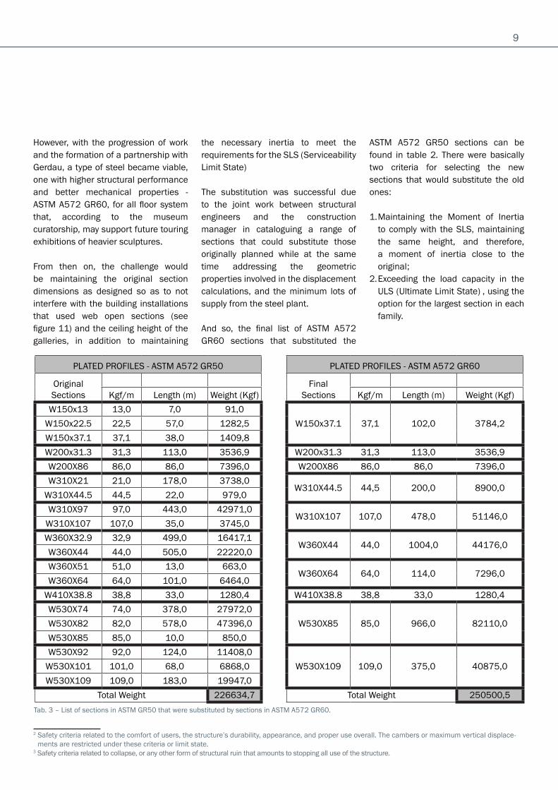
However, with the progression of work and the formation of a partnership with Gerdau, a type of steel became viable, one with higher structural performance and better mechanical properties - ASTM A572 GR60, for all floor system that, according to the museum curatorship, may support future touring exhibitions of heavier sculptures.
From then on, the challenge would be maintaining the original section dimensions as designed so as to not interfere with the building installations that used web open sections (see figure 11) and the ceiling height of the galleries, in addition to maintaining
the necessary inertia to meet the requirements for the SLS (Serviceability Limit State)
The substitution was successful due to the joint work between structural engineers and the construction manager in cataloguing a range of sections that could substitute those originally planned while at the same time addressing the geometric properties involved in the displacement calculations, and the minimum lots of supply from the steel plant.
And so, the final list of ASTM A572 GR60 sections that substituted the
ASTM A572 GR50 sections can be found in table 2. There were basically two criteria for selecting the new sections that would substitute the old ones:
1. Maintaining the Moment of Inertia to comply with the SLS, maintaining the same height, and therefore, a moment of inertia close to the original;
2. Exceeding the load capacity in the ULS (Ultimate Limit State) , using the option for the largest section in each family.
PLATED PROFILES - ASTM A572 GR50 PLATED PROFILES - ASTM A572 GR60
OriginalSections
Final Sections
Kgf/m Length (m) Weight (Kgf) Kgf/m Length (m) Weight (Kgf)
W150x13 13,0 7,0 91,0
W150x37.1 37,1 102,0 3784,2W150x22.5 22,5 57,0 1282,5
W150x37.1 37,1 38,0 1409,8
W200x31.3 31,3 113,0 3536,9 W200x31.3 31,3 113,0 3536,9
W200X86 86,0 86,0 7396,0 W200X86 86,0 86,0 7396,0
W310X21 21,0 178,0 3738,0W310X44.5 44,5 200,0 8900,0
W310X44.5 44,5 22,0 979,0
W310X97 97,0 443,0 42971,0W310X107 107,0 478,0 51146,0
W310X107 107,0 35,0 3745,0
W360X32.9 32,9 499,0 16417,1W360X44 44,0 1004,0 44176,0
W360X44 44,0 505,0 22220,0
W360X51 51,0 13,0 663,0W360X64 64,0 114,0 7296,0
W360X64 64,0 101,0 6464,0
W410X38.8 38,8 33,0 1280,4 W410X38.8 38,8 33,0 1280,4
W530X74 74,0 378,0 27972,0
W530X85 85,0 966,0 82110,0W530X82 82,0 578,0 47396,0
W530X85 85,0 10,0 850,0
W530X92 92,0 124,0 11408,0
W530X109 109,0 375,0 40875,0W530X101 101,0 68,0 6868,0
W530X109 109,0 183,0 19947,0
Total Weight 226634,7 Total Weight 250500,5
Tab. 3 – List of sections in ASTM GR50 that were substituted by sections in ASTM A572 GR60.
2 Safety criteria related to the comfort of users, the structure’s durability, appearance, and proper use overall. The cambers or maximum vertical displace-ments are restricted under these criteria or limit state.
3 Safety criteria related to collapse, or any other form of structural ruin that amounts to stopping all use of the structure.

10
The result was a difference of approximately 24 tons, or 10.5% compared to the initial weight of the floor beams, with a significant return in increased overload capacity, as shown in table 3. This difference in weight compared to the substituted material is due mainly to:
• The need to harmonize the gauges in order to ensure the supply contains within the minimum volumes required by the plant;
• The need to preserve sections with the same moment of inertia around the principal axis in terms of the restrictions on dimensions within the SLS (Serviceability Limit State);
• The need to keep the height configuration clear between floors, preserving the spaces conceived by the architecture, in addition to arranging the utilities in the so-called structural zone across the beams on the web oppenings;
• The lack of time in the project delivery schedule to recalculate the entire building with a higher strength steel, which would provide increased
optimization between structural capacity and final floor structure weight, however, to the detriment of making the final delivery on time;
In order to demonstrate the increased overload capacity mentioned above, three beams from different sections on separate floors and with different loads, located on the floors indicated in figure 9, were calculated for sampling. The premise of this recalculation was to work the beams to the maximum displacement for the SLS as provided for in NBR8800:2008 for this type of occupation, and to verify the overload limit that each of the beams of different kinds of steel could support, then compare them quantitatively.
The calculations were performed using the same section conditions for both types of steel in question.
After performing the calculations based on the premises described above, the results are described in table 4, the columns for which bear the following meanings:
• FLOOR – Description of the floor where the beam is located that was used as a sample;
• SECTION – Description of the nominal section according to the supplier’s catalogue for the beam that was used as a sample. After the letter “W”, the standard indicates the nominal height of the beam followed by the weight per linear meter of the section;
• GAP – Theoretical gap in support of the beam that was used as a sample;
• SC ORIG Δ =– Accidental load as per design, the final deflection of which (camber) was zero on the pre-camber installed;
• GR50 SC FINAL Δ = LIM – Maximum allowed accidental load, considering the GR50 steel and the deflection limit as per NBR8800:2008;
• GR60 SC FINAL Δ = LIM – Maximum allowed accidental load, considering the GR60 steel and the deflection limit as per NBR8800:2008;
• % GAIN – Percent gain in maximum accidental load between GR50 and GR60 steel.
PAV. SECTION GAP ORIG OLΔ = 0
GR50FINAL OLΔ = LIM
GR60FINAL OLΔ = LIM
% GAIN
3rd Floor W360x44,0 10.0 m 200 Kgf/m² 200 250 25,06th Floor W530x85,0 10.0 m 1000 Kgf/m² 1000 1250 25,08th Floor W530x109,0 10.0 m 600 Kgf/m² 1500 1800 20,0
Tab. 4 – Comparative percent gain using Grade 50 and Grade 60 steel.

11
Fig. 9 – Schematic view of the floors and the location of the beams used for the comparative analysis between the Grade 50 and Grade 60 steel.
As is shown, the percent gain for the sample from the 3rd FLOOR was 25%, from the 6th FLOOR, 25%, and from the 8th FLOOR, 20%, rather significant numbers considering the 10.5% increase in weight as shown in table 2 above, mainly considering the justification for this increase in weight listed in sequence.

12
All buildings with special designs require a single plan of action, and in this case, construction coordination devised a plan with 4 main steps, listed below:
1. construction of the diaphragm retaining walls to allow excavation of the basement floors so as not to affect the safety of the subway and neighboring buildings; construction of the concrete core where the elevators are housed, along with emergency stairs, technical areas, and service areas in exposed concrete, with forms in the framework that include inserts connecting to the beams to be supported on this core;
2. assembly of the steel structure using three primary mega trusses.
3. Execution of building installations, facade, and finishings within the standard proposed by the architects in order to meet the same specifications as the best international museums, while at the same time they are accepted by existing Brazilian standards, including the normative instructions of the Sao Paulo State Fire Department.
The execution of these steps on a plot without space for a construction site that meets the rules of restricted access to Paulista Avenue defined the special regime work day. This way, planned activities were carried out during the day, and the materials were received and used in real time in the short-term activities at night, given that there was no available space for storage.
The use of steel structures becomes essential in projects with such restrictions, and the main advantages in this regard may be enumerated thus:
• Less need for a storage area since the structural parts can be introduced from transport directly to their final position of assembly, or remain for relatively short amounts of time on the site, optimizing space;
• Reduced disturbance of local traffic when compared to the use of pumped concrete, which requires dozens of trucks that operate during the date and congest the accessways around the development, considering plots without construction site spaces;
• Speed of assembly, reducing disturbance of the neighborhood whose life comes to a stop for a long period of time, with large lifting equipment, assembly teams, noise, and higher risks of accidents when compared to the finishing stages;
On one of the fronts, after concreting each specific level of the core, specially designed inserts were carefully placed to serve as connection to the steel structure.
On another front, after the assembly of the main columns supported on these foundation transition structures, the first mega truss was assembled in the area of the Library, which then allowed the assembly of all support beams of the pre-cast slabs in this area.
The structural design provided an extremely lean structure with very interesting details, especially on the bolted connections, which, having been designed to be exposed, produced an aesthetically pleasing effect, following the concept of AESS (Architechturally Exposed Structural Steel), as seen in figure 6.
Manufacture and Assembly of the Steel Structure
Fig. 10 – The left-side view of the plot and the small space available for work. The right-side assembly of the mixed beams with connection to the metal inserts and to the concrete core Courtesy: José Luiz Canal
5 A concept mainly distributed in the USA in which the architecture explores the intended exposure of the metal structure to demonstrate the system’s entire functionality in addition to the aesthetic.

13
Another important aspect was the concern with the treatment that the structure would receive in order to meet the various necessary and rigorous demands, such as:
• Durability. Despite offering a good response in urban atmosphere with only the appropriate surface treatment, receipt of foundation and painting, the steel structure was hot galvanized (200 microns of zinc), receiving finish paint over intumescent paint
• Fire resistance. Due to severe regulation of the fire department that required the structure to support 120 min of fire time exposing a specialized company was hired to apply high performance intumescent painting from England
With progressing simultaneously on three fronts, as mentioned, at the peak of occupation during assembly and construction, while concreting the last levels of the concrete core, the steel structure of the Library was being assembled, and the installations and finishings of the lower floors were beginning.
With the disassembly of the vertical load transport crane and closure of the intended gap, the installations and finishing of the remaining floors may proceed.
Fig. 11 – Left - hot rolled beams from the floor system of one of the exhibition floors in GR60 steel, with web opening to allow integration of the services. Right - assembly crane, one of the positioned mega trusses, and concrete core Courtesy: José Luiz Canal

14
One year before inaugurating the museum to the public, the closure of the building began with special glass panels designed by Front and developed by Jetacorp. These panels consist of insulated double-lami-nated glass components weighing between 280 @ 320 kg each, which required the assembly of a system of platforms and a system of lifting the glass so that the assembly would be efficient and safe, with no accidents of any kind.
This facade system features high acoustic and thermal performance with its multiple layers and alterna-ting air chamber. The result was as aesthetic as it was comfortable in the aspects mentioned above, des-pite the intense noise coming from Paulista Avenue.
During the last year of construction, more than 250 professionals and over 40 companies from different areas of application were working on the development in a coordinated, accelerated effort, guided by a ca-refully planned schedule so that all actions were carried out on all ele-ven floors so as to avoid rework and maximize quality and safety.
Fig. 12 – Assembly of the glass enclosure system Courtesy: Andrade Morettin Arquitetos Associados

15
In addition to expanding the repertoire of the architecture, allowing for the working of larger gaps and higher ceiling heights, lending greater airiness to the complex, the steel structure in the IMS design also made it possible to overcome the building challenges imposed by the location of the site right on Paulista Avenue on a narrow plot surrounded by other buildings.
Structurally speaking, the main point to emphasize was the gain that was obtained, in a first with the use of niobium microalloyed high strength steel instead of the traditional ASTM A36 carbon-manganese steel, mainly due to factors such as better weldability, greater toughness, and greater resistance, the latter being directly connected to the reduction in the shape of sections and finally of the final weight of the structure.
In terms of structure, in a second moment, with the partial substitution of the ASTM A572 GR50 steel with the ASTM A572 GR60 steel, also micro-alloyed with niobium, which was shown to be quite efficient, increasing by 25% the accidental load capacity of the floors that would support exhibitions, as decided by the customer and thanks to the partnership with the Gerdau steel plant.
This study revealed that the gains in using GR60 steel would be considerably greater if they had been considered from the start of the project. Changes in stages of execution of work are a reality, and are often inevitable, but they come with their cost, and in this case it resulted in an increased weight of the structure, compensated by the increased load capacity of the floors.
This work also served to point out the extent to which expanding the offer to distribute higher performance steels on the part of the steel plants for use on a large scale by the structural engineers and architects could boost the use of this material in Brazilian civil construction, and perhaps stimulate the emergence of bolder projects in terms of architecture and structure, in addition to reaffirming the efficiency of using steel in construction where the speed and rationality of building processes are necessary, with the purpose of speed in assembly processes, optimizing space on construction sites, and extremely reduced impact on the routine of urban mobility in the area surrounding the buildings in large urban centers.
Conclusions
Technical Datasheet Architectural Design Andrade Morettin Arquitetos AssociadosStructural Design in both steel and concrete Ycon EngenhariaGeneral Management Canal&Musse Steel Structure Assembly and Manufacture Eleve Comércio e Montagem de Estruturas MetálicasSteel supplier Gerdau S.A. (Perfis e Chapas até 22 mm)
Usiminas S.A. (Chapas acima de 22 mm)Total weight of the Steel Structure 556 ton.
SupportCBMM – Companhia Brasileira de Metalurgia e Mineração (Brazilian Mining and Metallurgy Company)IMS – Instituto Moreira SallesGerdau S.A.
ReferencesMONOLITO. São Paulo: Editora Monolito, n. 8, abril/maio 2012.SILVESTRE et al. High Strength Steel as a Solution for the Lean Design of Industrial Buildings.Journal of Material Research and Technology. Amsterdan. p. 35-41. Apr. 2012.
InterviewsMarcelo Morettin and Vinícius Andrade – architects responsible for the design, responsible for Andrade Morettin Arquitetos AssociadosJânio Gomes – executive director of the Sao Paulo IMSJosé Luiz Canal – civil engineer, project manager, responsible for Canal&MusseYopanan Rebello – civil engineer, responsible for designing the concrete and metal structures, responsible for Ycon EngenhariaWilson Ramos da Silva Filho – civil engineer, general director of Eleve Comércio e Montagem de Estruturas Metálicas, responsible for manufacturing and assembling the structure
Further information can be obtained at www.niobium.tech/structural
v12.2020 Copyright © 2020 CBMM
World leader in the production and commercialization of Niobium products, CBMM has customers in over 40 countries. With headquarters in Brazil and offices and subsidiaries in China, Netherlands, Singapore, Switzerland and the United States, the company supplies products and cutting-edge technology to the infrastructure, mobility, aerospace and energy sectors. CBMM was founded in 1955 in Araxá, Minas Gerais, and relies on a strong technology program to increase Niobium applications, growing and diversifying this market.